

Page 1

HW
AA
NL
GL
E
R
U
N
I
T
PLASMA MONITOR (DISPLAY)
WALL HANGER UNIT
INSTRUCTION MANUAL
DP-HG22
Thank you for purchasing the Daewoo Electronic Plasma Display Wall Hanger Unit. This
wall unit is specifically designed for use with the Daewoo Plasma Display. To ensure the
safe operation of the unit, please read these instructions before installing.
Page 2

1
TABLE OF CONTENTS
1. Check for enclosed parts
..............................
2
2. Important Safety Instructions
........................
3
3. Assembly Instructions
...................................
6
4. Adjusting angles after installation
................
12
*
To install the wall hanger unit, Please
consult an Authorized service center first.
Page 3
PLASMA DISPLAY HANGER UNIT
2
HW
AA
NL
GL
E
R
U
N
I
T
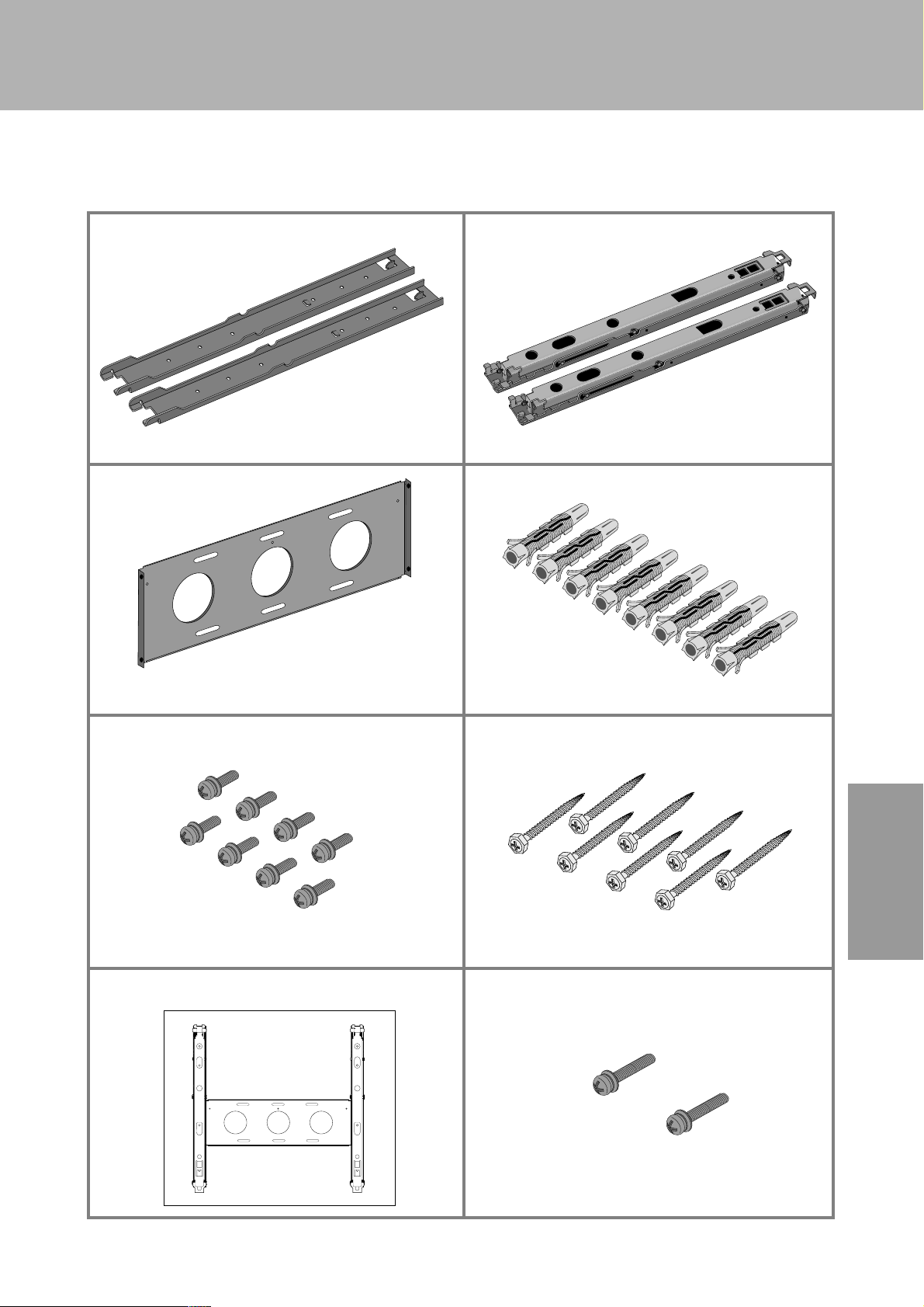
1. PLEASE CHECK THE ITEMS SHOWN BELOW
(2)
FRAME SET A FRAME SET B
CONNECTING FRAME CONCRETE WALL ANCHOR
M5 SCREWS (20 MM) WALL SCREWS
PAPER PATTERN PLAN M5 SCREWS (30MM)
(2)
(1) (8)
(12) (8)
(1) (2)
Paper pattern plan
Page 4
3
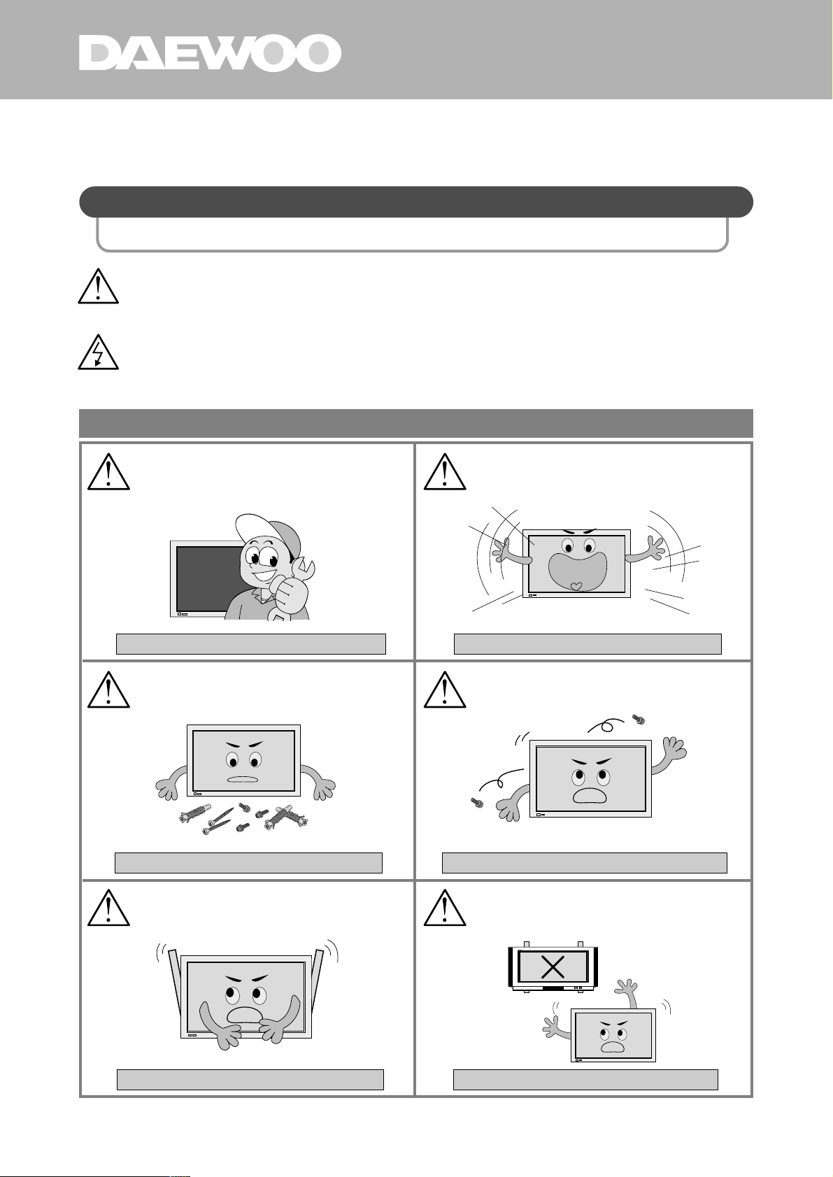
2. IMPORTANT SAFETY INSTRUCTIONS
WARNING : Disregarding these instructions can result in serious injury .
CAUTION : Disregarding these instructions will result in the mistreatment of
the unit and can result in injury or damage to the unit.
PLEASE KEEP THESE INSTRUCTIONS FOR YOUR SAFETY AND TO PREVENT ANY DAMAGE TO THIS UNIT.
PLEASE FOLLOW THESE INSTRUCTIONS FOR YOUR SAFETY
(Failing to do so may cause the unit to fall and break) (Failing to do so may cause the unit to fall and break)
(Failing to do so may cause the unit to fall and break) (Failing to do so may cause the unit to vibrate and to fall)
(Failing to do so may cause the unit to fall and break) (Failing to do so may cause the unit to fall and break)
To install the wall hanger unit, please consult
an Authorized service center first.
The wall hanger unit needs to be installed
securely enough to handle earthquakes or
lengthy periods of vibration.
When assembling, do not use any parts other
than those enclosed and secure all parts tightly.
Do not leave out any part when assembling.
Please install all parts to where indicated.
Do not alter or modify any parts Do not use the wall hanger unit with other products. This
wall hanger unit is specifically designed to fit the Daewoo
Plasma Display.
*
PLEASE CONSUL T AN AUTHORIZED SERVICE CENTER T O INST ALL THE W ALL HANGER UNIT
WARNING
CAUTION
Page 5

PLASMA DISPLAY HANGER UNIT
4
HW
AA
NL
GL
E
R
U
N
I
T
Special care is needed when installing onto the
wall due to its weight (35Kg)
When installing on a concrete wall
Please be sure to use the enclosed concrete
anchors.
When installing on a wooden wall
take special
care as the unit may require extra support to
uphold the weight of the plasma display.
When installing, please wear working gloves.
Be sure that no one is around to distract you
during the installation process.
When installing, please have at least two
people.
Please choose a wall that is straight so that the
plasma display can be securely attached onto the
wall.
Place a protective covering over the surface you will
be working on when handling the plasma display and
the wall hanger units.
*
PLEASE FOLLOW THESE SAFETY PRECAUTIONS WHEN INST ALLING OR HANDLING
(If done with bare hands, it may result in injury)
(It may result in injury to you or others)
(If attached on an unstable wall, the unit can fall and
break)
(Because of its weight, the unit may fall and can cause
injury)
(Failing to do so may result in unwanted marks on the
unit)
After installing, please be sure to check to see if the
unit has been secured firmly.
Page 6

5
It is important to use the paper pattern plan to choose the proper place; otherwise, it can result in
damage to the wall and you will not be able to install the unit
If proper spacing is not allowed, it may cause the plasma display to overheat, which can cause fire or
damage to the unit
When installing, please use the size referenced below to choose a place, and attach
the paper pattern plan to the wall.
When installing, please allow at least 15 cm at the top, bottom, left and right on the
wall, and clear all items away from where the unit will be.
*
PLEASE FOLLOW THESE SAFETY PRECAUTIONS WHEN INST ALLING OR HANDLING
519.5
.
Measurement unit : mm
519.5
314
314
15cm
15cm
15cm
15cm
Paper pattern plan
Page 7

PLASMA DISPLAY HANGER UNIT
6
HW
AA
NL
GL
E
R
U
N
I
T
3. ASSEMBLING INSTRUCTIONS
PREP ARATION
WHEN THE PLASMA DISPLA Y IS ATT ACHED T O THE STAND
TO DETACH THE STAND FROM THE PLASMA DISPLAY
TO PLACE THE PROTECTIVE CAPS
.
To avoid unwanted marks on the unit, place
a protective covering over the surface you
will be working on and lay the plasma
display as shown below.
.
Unscrew the secured 2 screws completely
and Pull the stand away from the plasma
display to detach.
.
There will be two holes where the stand
has been detached.
.
Put the protective caps on the holes and
use the screws to secure tightly .
1
2
Screws
Caps
Holes
Page 8

7
INSTALLING THE WALL FRAME SET A ON THE PLASMA DISPLAY PANEL
HOW T
O INSTALL FRAME SET A ON THE UNIT
.
To avoid unwanted marks on the unit, place
a protective covering over the surface you
will be working on and lay the plasma display
as shown in the picture below.
.
When securing frame set A to the plasma display panel, make sure that they match the holes correctly.
.
If the holes are matched incorrectly, the installation will not be successful.
.
Place frame set A on the left and right
side of the unit and use the enclosed
screws (M5) to secure them tightly.
(left and right 2 each)
2
Note
CORRIGENDA
MODEL: DP-HG22
.
Replace the previous instruction (#2) with the following updated one.
.
Four M5 screws are not used out of total number.
.
Make sure the installation is secure.
.
Installation by professional is preffered.
.
Contact infomation for any question.
1-800-DAEWOO-8 #8
1-201-964-9349
Service@daewoodigital.com
Page 9

PLASMA DISPLAY HANGER UNIT
8
HW
AA
NL
GL
E
R
U
N
I
T
INSTALLING WALL FRAME SET B AND CONNECTING FRAME
INSTALLING WALL FRAME SET B AND CONNECTING FRAME.
ATTACHING PAPER PATTERN PLAN ON THE WALL
.
Place frame set B on the left and right side of
the unit and use the enclosed screws (M5) to
secure them tightly.
.
Place the enclosed paper pattern
plan (actual size) on the wall with
glue or tape.
.
Drill holes on the wall as indicated
on the paper pattern plan with a
hand drill (power drill) and hammer
in the concrete anchors (8) firmly.
Connecting Frame
Frame set B
Hand drill
Paper pattern plan
Paper pattern plan
1
2
.
Please be sure to not force an
adjustment when connecting frame
set B and connecting frame.
.
Otherwise, it will create problems
when connecting to frame set A.
Note
Page 10

9
INSTALL THE WALL FRAME SET ON THE WALL
.
Install the wall frame set on the wall by matching the concrete anchors with the holes,
then use the wall screws (8) to secure tightly.
Paper pattern plan
3
INST ALLING ON THE WALL HELD BY SUPPORTING WOODEN STRUCTURE
.
If it is not feasible to attach frame set B firmly and completely, due to the distance
between the two supporting woods; attach one side of the frame set B firmly to the
supporting wood, and use appropriate remaining holes(6) to attach the frame set B
to the supporting wooden structures.
4
Paper pattern plan
Page 11

CONNECTING UPPER PART OF FRAME SET A AND FRAME SET B
.
Insert the upper part of frame set A (X) to frame
set B (Y) as indicated below.
*
At least two people are needed to put these frames together.
(X)
(Y)
(Z)
Frame set B
Frame set A
1
PLASMA DISPLAY HANGER UNIT
10
HW
AA
NL
GL
E
R
U
N
I
T
CONNECTING LOWER PART OF FRAME SET A AND FRAME SET B
.
Adhere Frame set B to Plasma Display unit, then, take the lower part of Frame
set B as pictured below and push the (Z) part up gently then let go to connect.
2
INSTALLING PLASMA DISPLAY ON THE WALL
Page 12

11
TO PROVIDE THE SECUREST FIT
.
After installing plasma display and wall frame sets, for a more secure fit, secure
M5 screws (M5x30) on the (Z) part so that (Z) will not move up and down as
shown in the picture below.
3
Page 13

PLASMA DISPLAY HANGER UNIT
12
HW
AA
NL
GL
E
R
U
N
I
T
4. ADJUSTING ANGLES AFTER INSTALLATION (10˚, 15˚, 20˚)
HOW TO ADJUST VIEWING ANGLES
THE FIGURES BELOW DISPLAY THE POSSIBLE PLASMA DISPLAY ANGLES.
.
Take out the screws from the upper part of the frame.
.
Insert the upper part of the frame set B angle adjustment lever
to its gap.
1
2
Lever (X)
0
˚
10
˚
15
˚
20
˚
.
As pictured below, pull and
adjust the lever (X) to fit your
desired viewing angle.
.
This adjustment needs to be done when the plasma display is tightly secured. Otherwise, the unit
can fall and break.
.
Please retain the two screws for future angle adjustments.
.
At least two people are needed when modifying angle adjustment.
Note
 Loading...