

Daewoo DMB-1812LH Schematic
CONTENTS
1. Specifications..........................................................................................................2
2. Outline and Dimensions.........................................................................................3
3. Installation Section..................................................................................................6
4. Operation ..............................................................................................................23
5. Wiring Diagram.....................................................................................................36
6. Refrigerant Cycle..................................................................................................38
7. Control Block Diagram.........................................................................................39
8. Trouble Shooting...................................................................................................41
9. Key Components of Electronic Circuit.................................................................71
10. Disassembly Instructions .....................................................................................75
1) Indoor Unit........................................................................................................75
2) Outdoor Unit.....................................................................................................77
3) Exploded Diagram (Indoor Unit)......................................................................78
4) Exploded Diagram (Outdoor Unit)...................................................................83
5) Control Box Assembly......................................................................................85
Contents
2
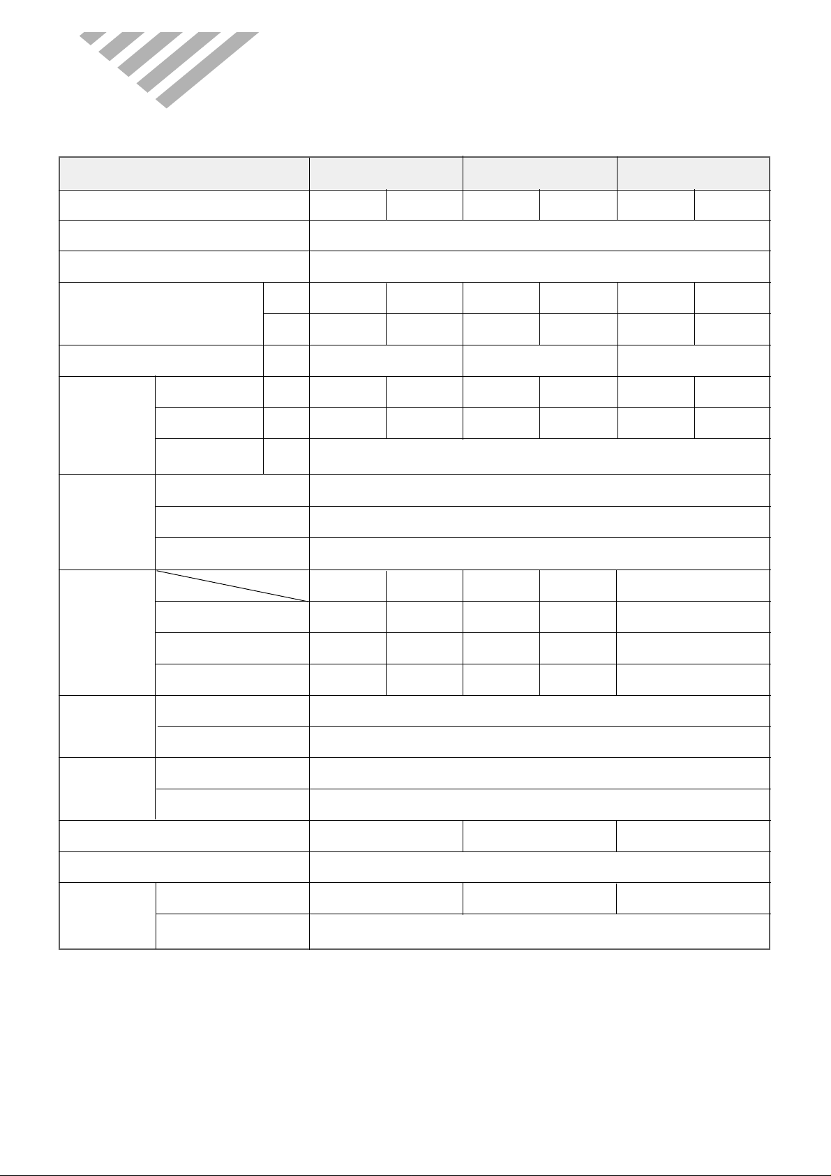
1. SPECIFIC A TIONS
MODEL DMB-1812LH (9K) DMB-1812LH (12K) DMB-1812LH (9K+12K)
Function
Class T
Power AC 220-240V, 50Hz
Capacity
Dehumidification 1.15 2.10 3.25
Running Current
Power Input
Starting Current 49 A
Type Rotary (Hitachi)
Model SHW33TC4-U
Capacitor 50µF/370VAC
Type Capacitor Motor Model Number Control Capillary
Charge Quality 1700 g
Type Flare
OD (Liquid/Suction) 1/4” (6.35 mm) / 1/2” (12.7 mm)
Indoor Unit Dimension (W x H x D) 750 x 245 x 174 925 x 285 x 194 Outdoor Unit Dimensions (W x H x D) 872 x 675 x 325
Net Weight
Indoor Unit (kg) 7.00 9.70 Outdoor Unit (kg) 55.94
Electrical
Data
Compressor
Fan
Motor
Refrigerant
(R-22)
Connection
DMB-1812LH
W
Btu/h
l/h
A
W
A
Cooling Heating Cooling Heating Cooling Heating
2637.6
9000
2637.6
9000
3516.8
12000
3516.8
12000
5275.2
18000
5275.2
18000
8.0
1800.0
8.0
1800.0
8.0
1800.0
8.0
1800.0
8.5
1850.0
8.0
1800.0
Indoor Unit
Cross flow fan
1.0µF 400VAC
YDK-8-4B(Xiangming)
Outdoor Unit
Propeller
fan
5/45µF 400VAC
OSME-806DERC
Indoor Unit
Cross flow fan
1.0µF 400VAC
YDK-8-4B(Xiangming)
Outdoor Unit
Propeller
fan
5/45µF 400VAC
OSME-806DERC
3
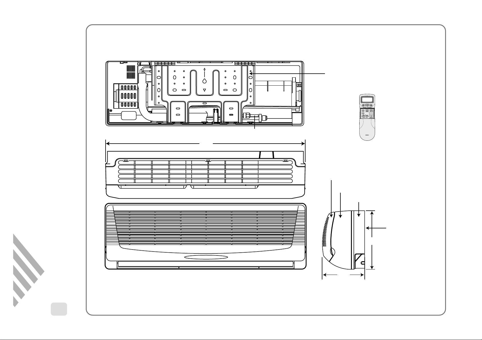
750
Plate Mounting
REMOCON
Connecting Pipe
Grille Insert
174
245
REMOTE CONTROLLER
Frame Grille
Body
Plate Mounting
2. OUTLINE AND DIMENSIONS
1
INDOOR UNIT
DMB-1812LH (900BTU/h)
4
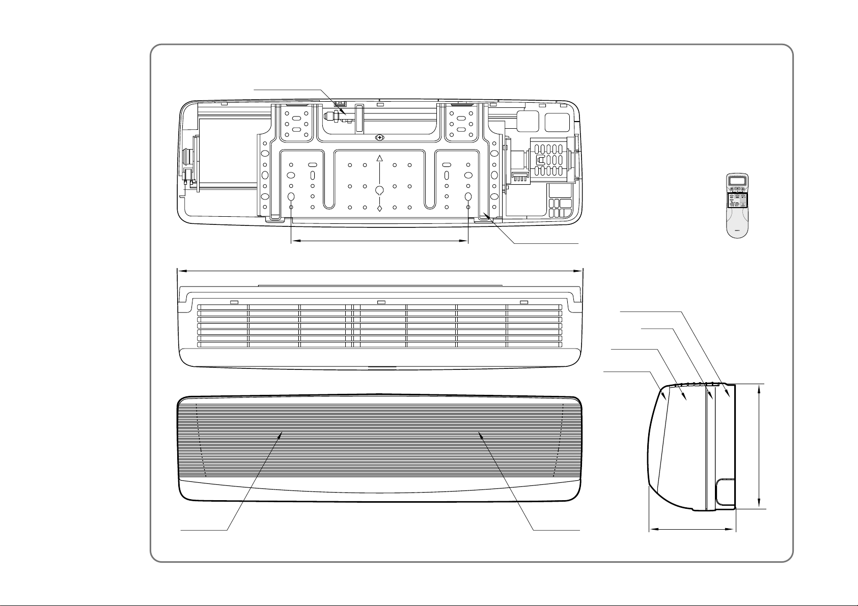
REMOCON
Filter - L Filter - R
Grille Insert
Frame Grille
Body
Plate Mounting
Connecting Pipe
Plate Mounting
406
194
285
925
REMOTE CONTROLLER
DMB-1812LH(12000BTU/h)
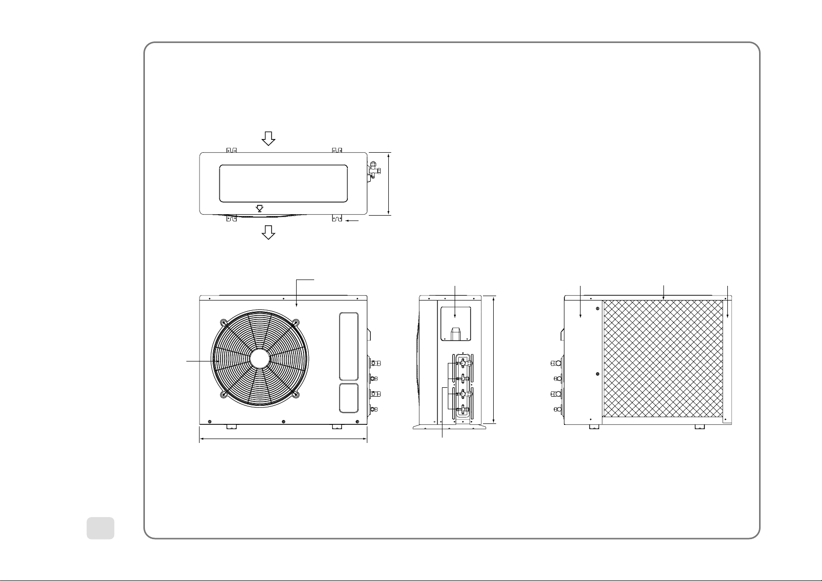
5
Inlet
325
Foot
Cabinet Front Cover Service
Outlet
Outlet
675
Service Valve
872
Cabinet Side Guide PostPanel Top
2
OUTDOOR UNIT
DMB-1812LH
6
This Installation section explains how and where to connect this new air conditioner. Please read make sure all accessories are included as shown below and read manual thoroughly. This Installation section is provided to assist the person knowledgeable in air conditioner installation and should not be installed by anybody who is not thoroughly familiar
with this type of installation. Please contact a professional installer if necessary.
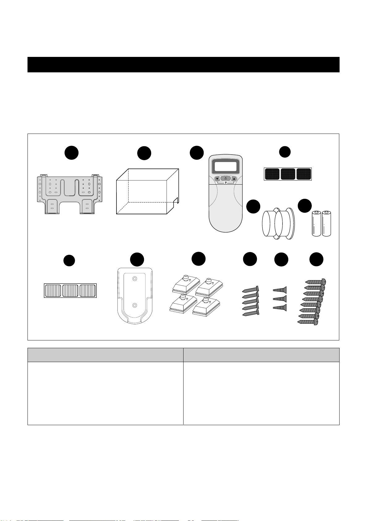
ACCESSORIES SUPPLIED WITH THE UNIT:
COPPER TUBING:
Copper tubing supplied is available at most dealers or A/C shops. Make sure the new copper tubing has the same
specifications and diameter as the original copper tubing and is as short as possible.
Note:
The remainders except for No. 2, 7, 11 are contained in the indoor boxes.
BASIC A CCESSORIES
No. Description Qty.
1 Wall Bracket 2
2 Outdoor Unit Cover 1
3 Remote Controller
4 Deodorizing Filter
5 Electrostatic Filter
2
2
2
6 Remote Holder 2
No. Description Qty.
7 Foot Cushion 4
8 Concrete Nails 10
9 Remote Holder Screws 6
10 Wall Bracket Screws 16
11 Wall Cap 4
12 Battery 4
Installation Section
1
2
5
6
3
7
TEMP.
ON/OFF
SWING
MODE
FAN SPEED
SLEEP
TIMER RESET
ON OFF ENTER CANCEL
11
8
9
4
12
10
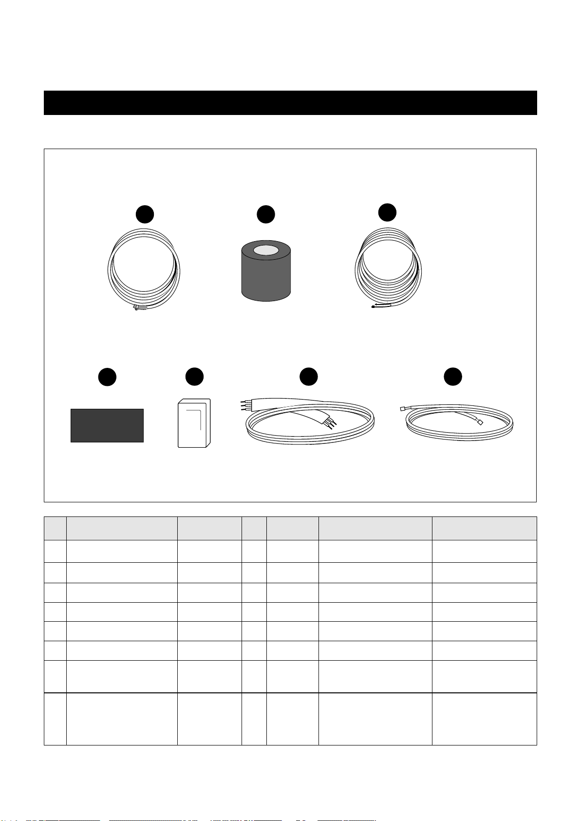
OPTIONAL A CCESSORIES
ACCESSORIES NOT SUPPLIED WITH THE UNIT:
No. Description Part No. Qty Material Size Remark
1 Drain Hose Extension 3103200400 2 ID19.6 X 2m PVC Pipe
2 Tape 2TQ1008000 2 PVC 80W X 0.1T X 3.5m
3 Copper Tubing Extension 3100002600 2
1/2", 1/4" Copper Tube
4 Insulator Plate 3103301000 2 F-US 225 X 120 X 8T
5 Putty 2221040001 2 80g
6 Connection Cord 3102797200 2 3P X 6m
7 Signal Connection Cord 3112704600
311270470011
5P x 3m White
5P x 3m Red
Complete Optional 3100400000 1
Accessories
(1, 2, 3, 4, 5, 6, 7)
7
1 2
3
4
5 76
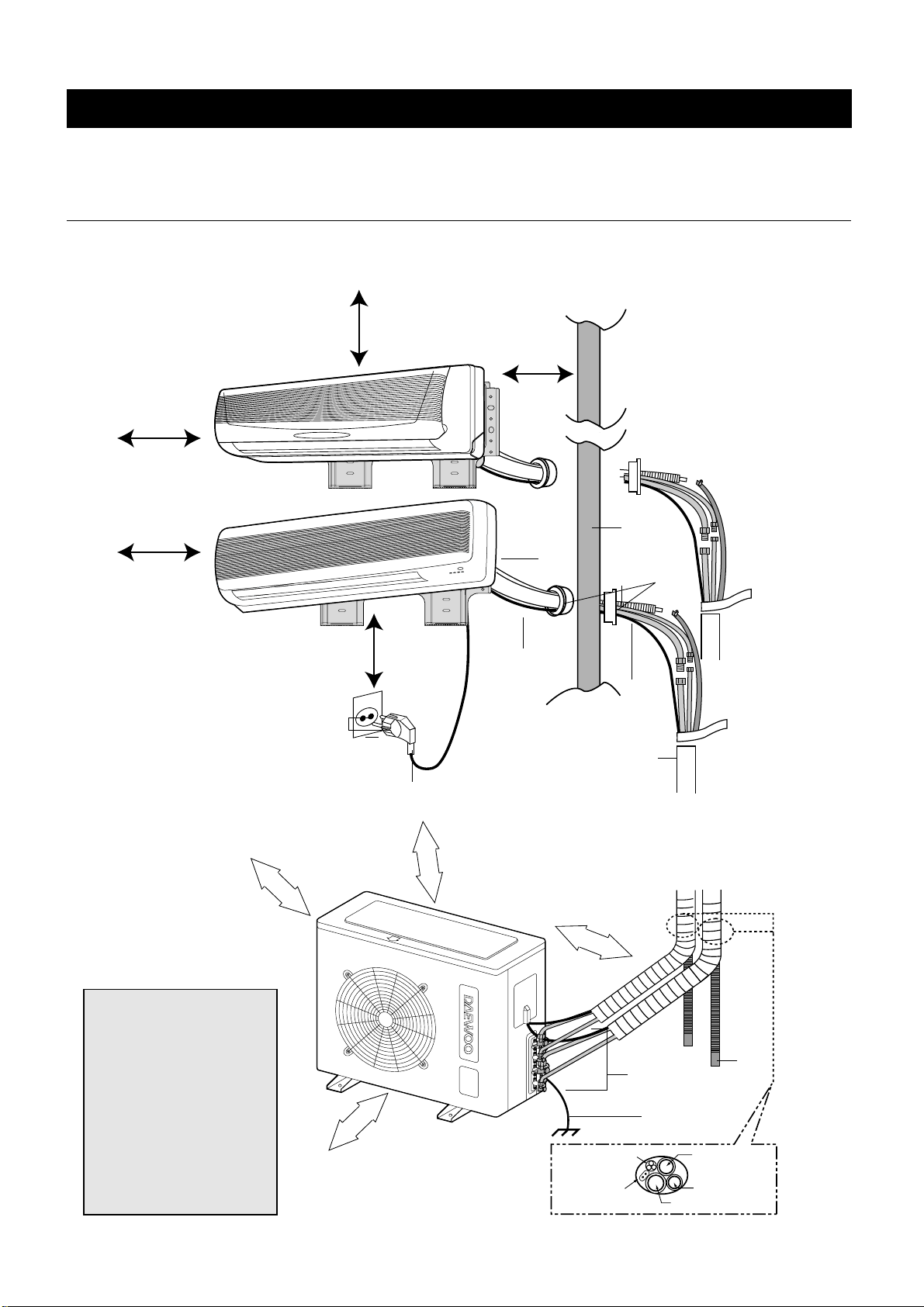
INSTALLATION DIAGRAM
Below is an overview for the connection of the Indoor unit to the Outdoor unit. The pages following will give detailed
instructions for full installation. Remember to read the complete Installation section and follow all the safety instructions
fully when installing the Indoor and Outdoor units.
OVERVIEW
This appliance must be installed according to national power supply acquirement.
NOTES:
• After installation it must be
possible for the user to dis connect the power supply
plug.
•
If the AC outlet is a 3pronged type or other, have
an electrician install a new
outlet.
• Contanct service man when
replace the power cord set.
• The specification of AC con nection is 1.5mm
2
X 4PX6m.
Drain
Hose
Ground Wire
(Not Supplied)
1/2" side piping
Connecting cable
Signal Wire
1/4" side piping
Drain Hose
Wall
Wall
Cap
Drain
Hose
Pipes
(Not Supplied)
AC
Connection
(Not Supplied)
Wrap with
Tape
AC Outlet
and Plug
Copper
(12000
BTU/h)
(9000BTU/h)
Tubing
At least 30cm
(11.8in) from unit
Maximum Height 7M (21Ft)
Maximum Length 15M (49Ft)
Any tube length between 7 and 15 meters must
be precharged with freon using the following calulation: (Length – 5) x 30 grams
Adding additonal tubing will decrease efficiency
60
cm
23.6
inches
cm
10
cm
3.9 inches
60
23.6
inches
70
cm
27.6
inches
Plug into 220V~240V
AC Outlet
10cm (3.95in)
from ceiling
30cm (11.8in) from
side wall
10cm (3.95in) from
side wall
10cm (3.95in) from
side wall
Wall
Bracket
8
INSTALLATION
1. Determine the type of wall (sheetrock, concrete, etc.)
and make sure it is strong enough to hold indoor unit.
Select an approximate position for the unit, taking the
required distances away from walls/AC outlet into
consideration.
INDOOR UNIT
• Do not install the unit in an area with direct sunlight, near
heat sources (radiator, etc.), or an area where leakage of
flammable gas may be expected.
• Select a position in the room, high on the wall, where the
whole room can be uniformly cooled.
• Select a location that can hold the weight of the unit and
where the copper tubing, drain hose and Indoor to Outdoor
Wire have the shortest distance to the Outdoor unit.
• Make sure the Indoor unit is installed at least 10cm (3.95in)
away from the top and left side wall and at least 30cm
(11.8in) from AC outlet and right side wall (see Overview
figure on previous page).
OUTDOOR UNIT
• Do not install the unit in an area near heat sources,
exhaust fans, or an area where leakage of flammable gas
may be expected.
• Do not install the unit in a humid, damp or uneven location.
• Select a location that is well ventilated .
• Leave enough room around the unit for air intake, exhaust
and possible maintenance.
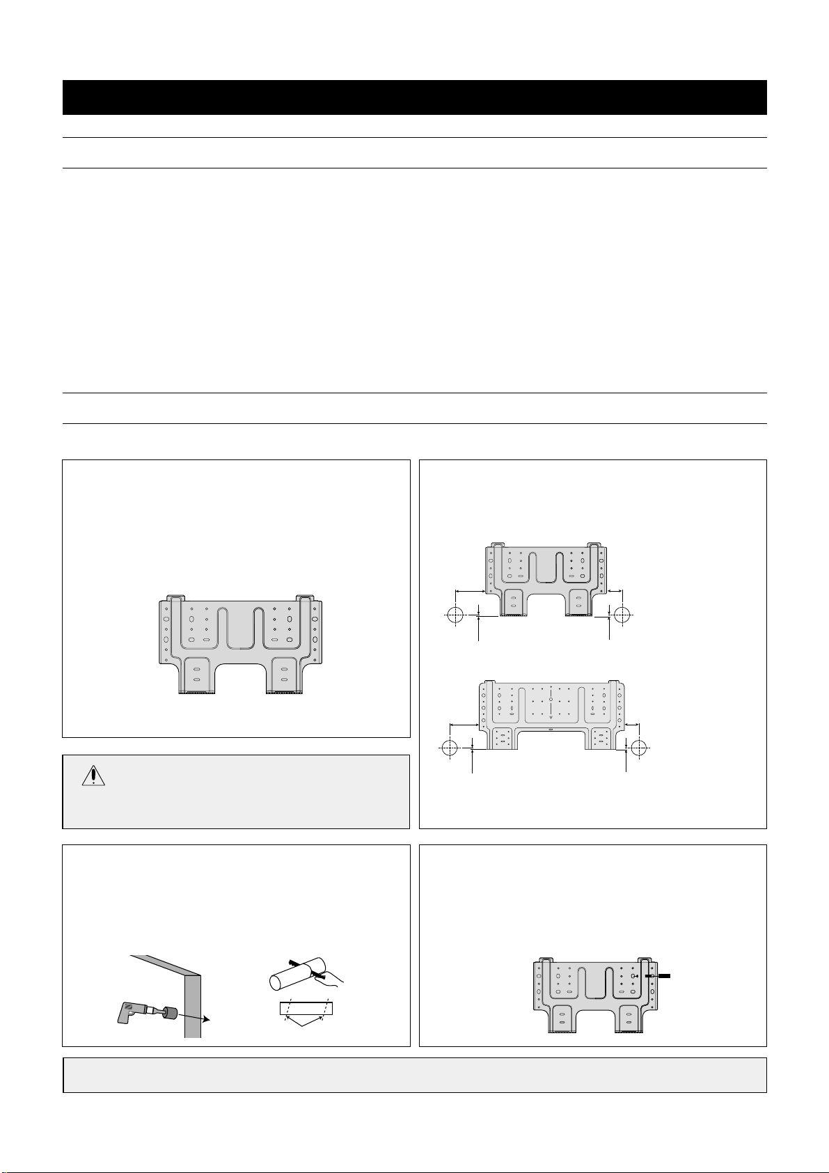
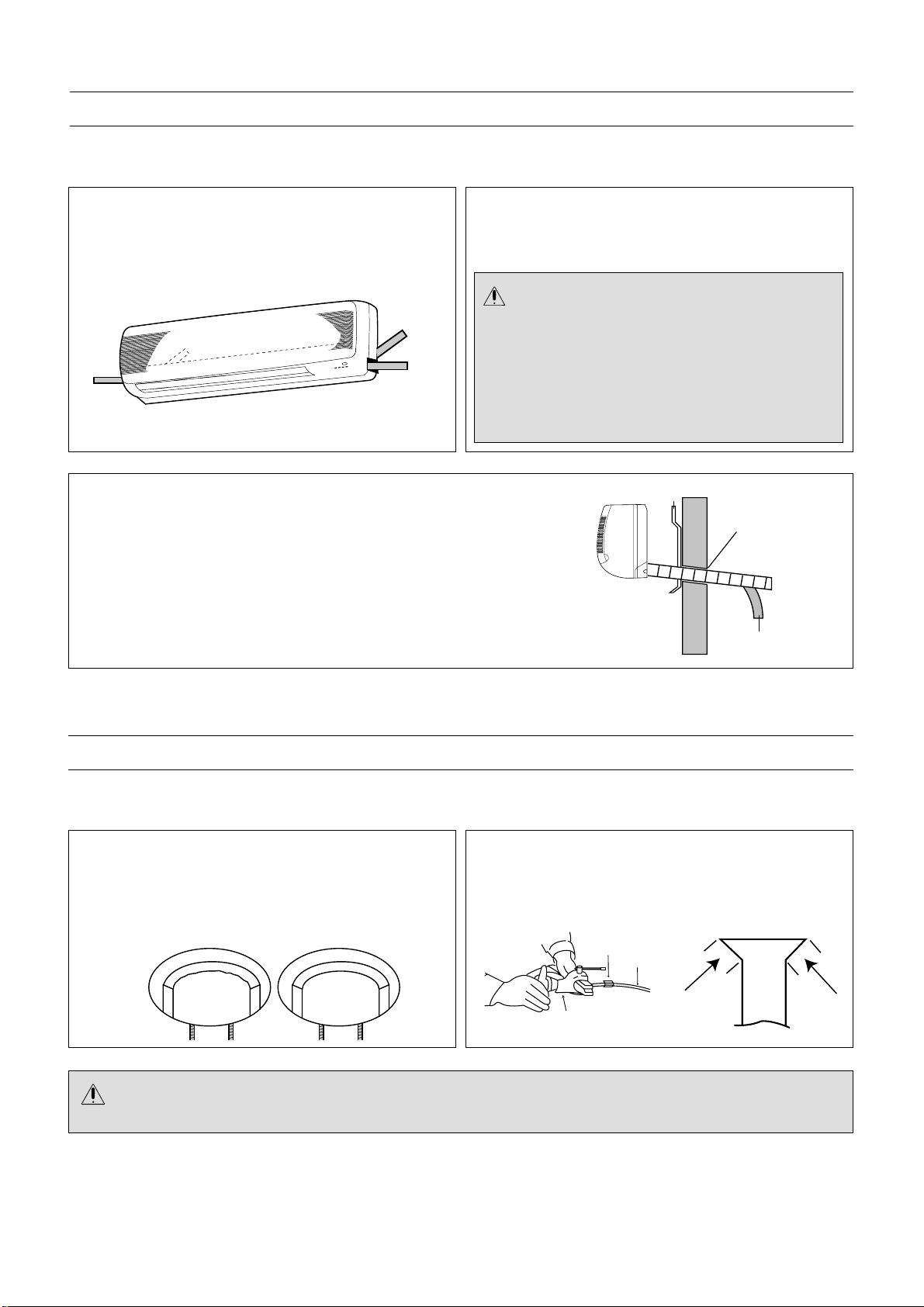
2. Determine if the hole is to be made at the left or right
hole location.
10 mm
10 mm
150 mm 60 mm
3. Using drill with hole-cutting attachment or equivalent, cut
a hole 65mm (2.56") in diameter. The hole should be
made at a slight downward slant to the outdoor side.
Measure the thickness from the inside to outside edges
and cut a PVC pipe at a slight angle 1/4" shorter than the
thickness of the wall and insert pipe in wall.
4. For sheetrock, wooden or similar wall, measure down
from the ceiling using a level or tape measure and attach
the wall bracket to the wall using 4 screws. If you are not
able to line up the holes with the beams, use toggle
bolts. Make sure the wall bracket is even and flush
against the wall.
Indoor Outdoor
Cut at slight angle
CAUTION
• Before making hole, make sure there are no studs, pipes,
electrical wiring or conduit directly behind the area to be cut.
For Concrete, or similar type wall, make holes into the wall and insert concrete nails instead of screws.
INST ALLING THE WALL BRA CKET:
To install the wall bracket, follow the procedures below. One hole is required for the tubing and may be either on the left or right side.
SELECTING A SITE:
DMB-1812LH
(9000BTU/h)
DMB-1812LH
(12000BTU/h)
10 mm
10 mm
150 mm 60 mm
9
DMB-1812LH(9000BTU/h)
NOTES:
•
This appliance must be installed according to National
power supply requirement.
•
If the supply cord is damaged, it must be replaced by
the manufacuturer or its service agent or a similarly
qualified person in order to avoid a hazard.
•
Make sure the Indoor unit’s AC cord is not connected to
AC power when connecting the indoor/outdoor wire.
•
When connecting wires, make sure they are fully insert-
ed and minimum copper wire is exposed. If they are
not, shorting, overheating, no operation, etc. may occur.
•
Be sure to comply with local codes on running a wire
from the indoor to the outdoor unit.
2. Fish the indoor/outdoor wire from the rear of the
indoor unit through the front of the unit. For easier
connection, make sure enough wire is pulled through
the front.
Use the wire as shown below:
INSTALLING THE INDOOR/OUTDOOR WIRE TO THE INDOOR UNIT FOR AC CONNECTION
The Indoor/Outdoor wire is used to supply AC from the Indoor unit to the Outdoor unit. To install the indoor/outdoor wire,
follow the procedures below.
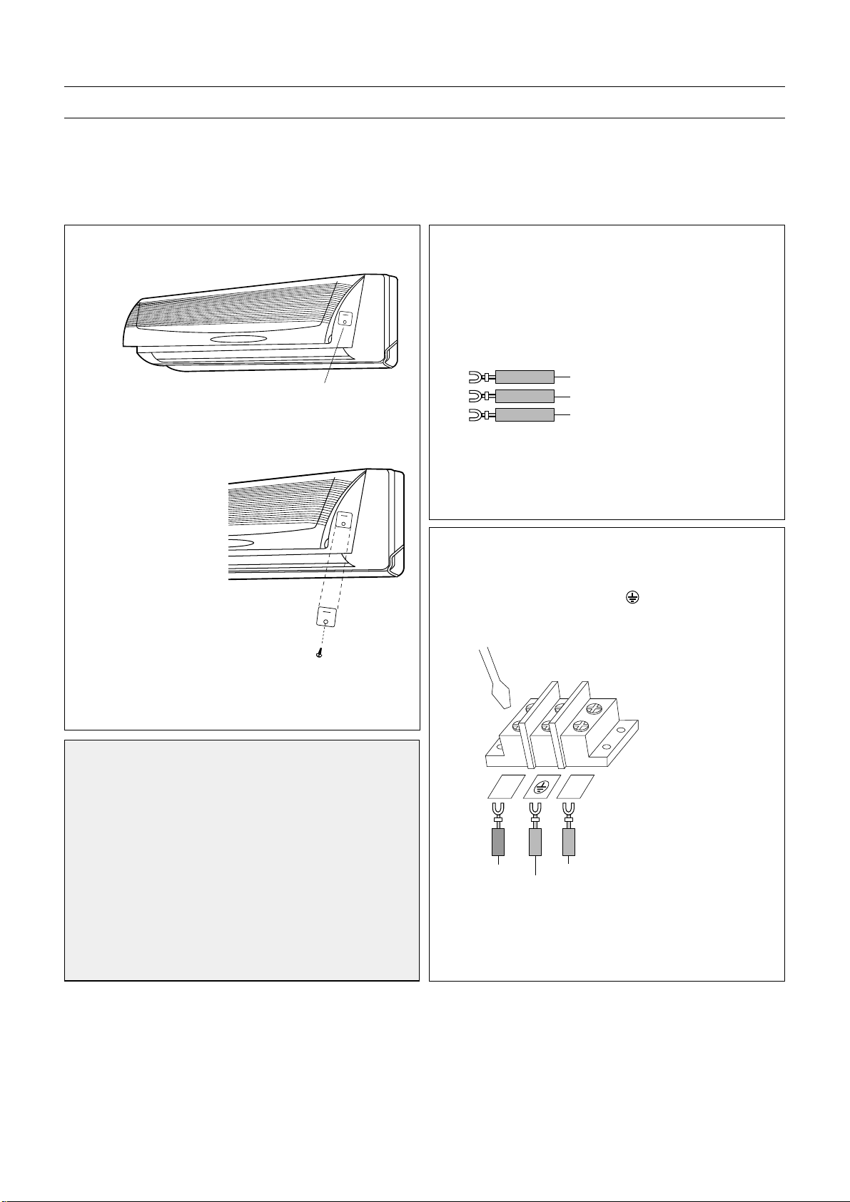
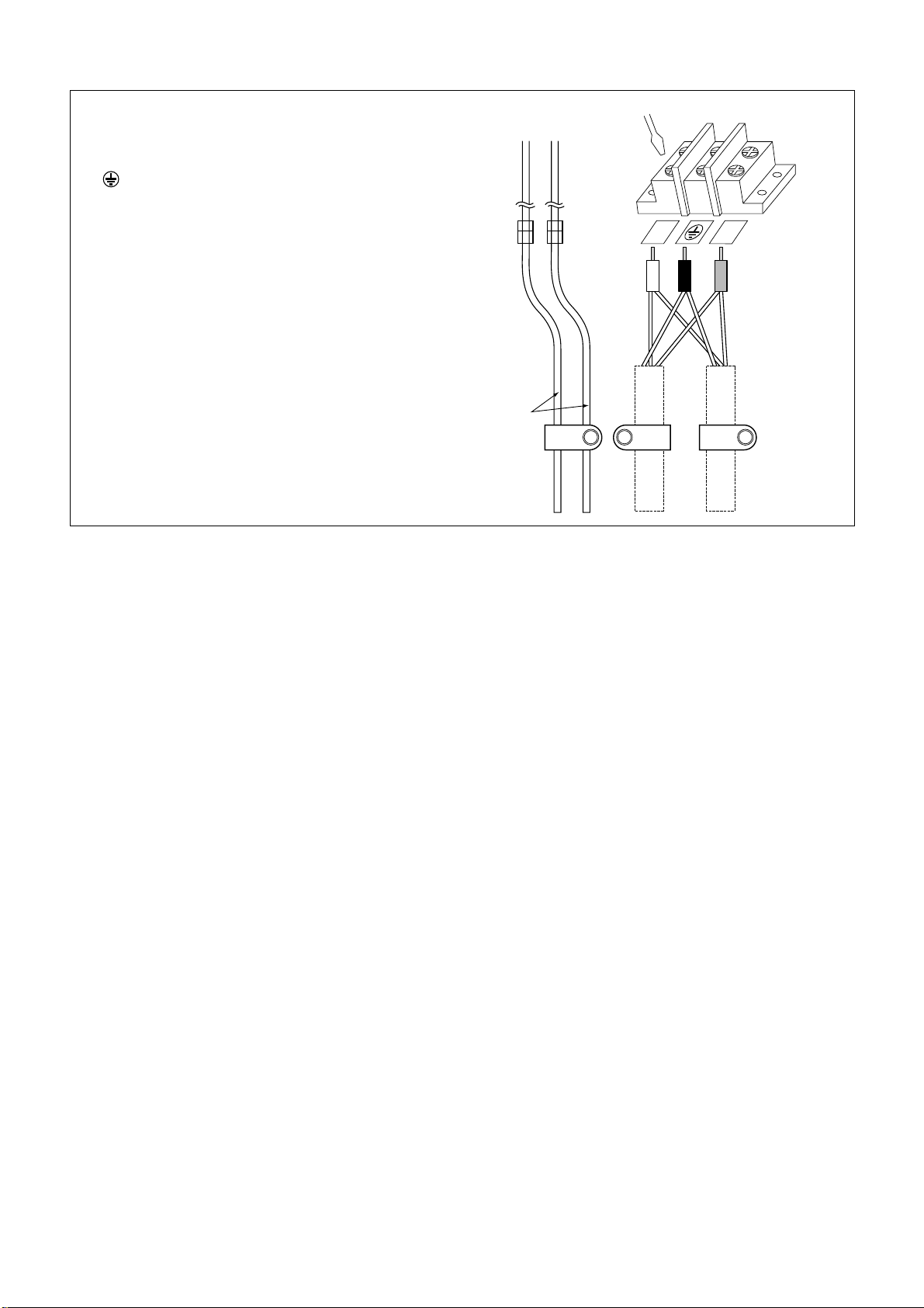
3. To connect wires, loosen the screw in the Terminal
Block and insert the correct wires like following figure.
Connect the Brown wire to the “Y” connection,
Yellow/Green wire to the “” connection and the
Blue wire to “L” connection.
Y
L
Brown Blue
Yellow/Green
DMB-1812LH
(9000BTU/h)
DMB-1812LH
(9000BTU/h)
Blue
Yellow/Green
Brown
Connection cover
Screw
1. Open the connection cover on the indoor unit to
access the connection area.
Remove the Connection
Cover.
• Loosen the screw fixed at
the Connection Cover.
• Remove the
Connection Cover.
10
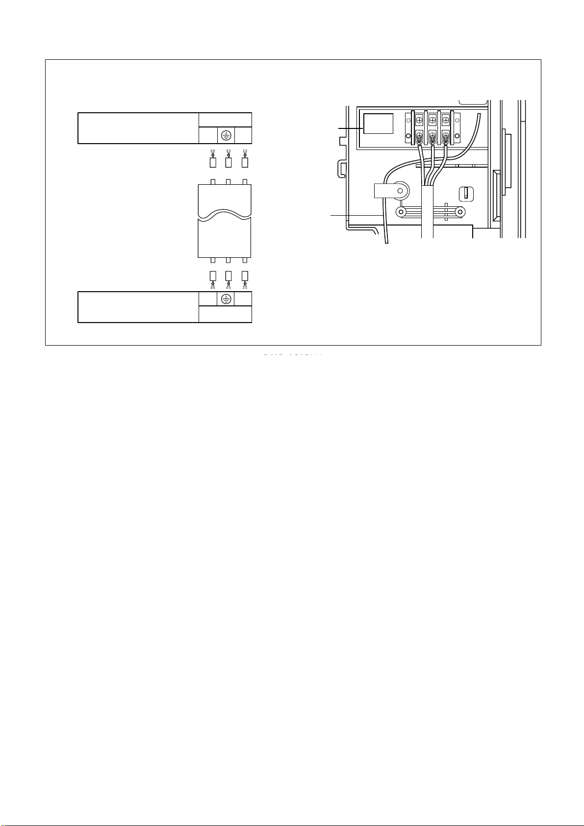
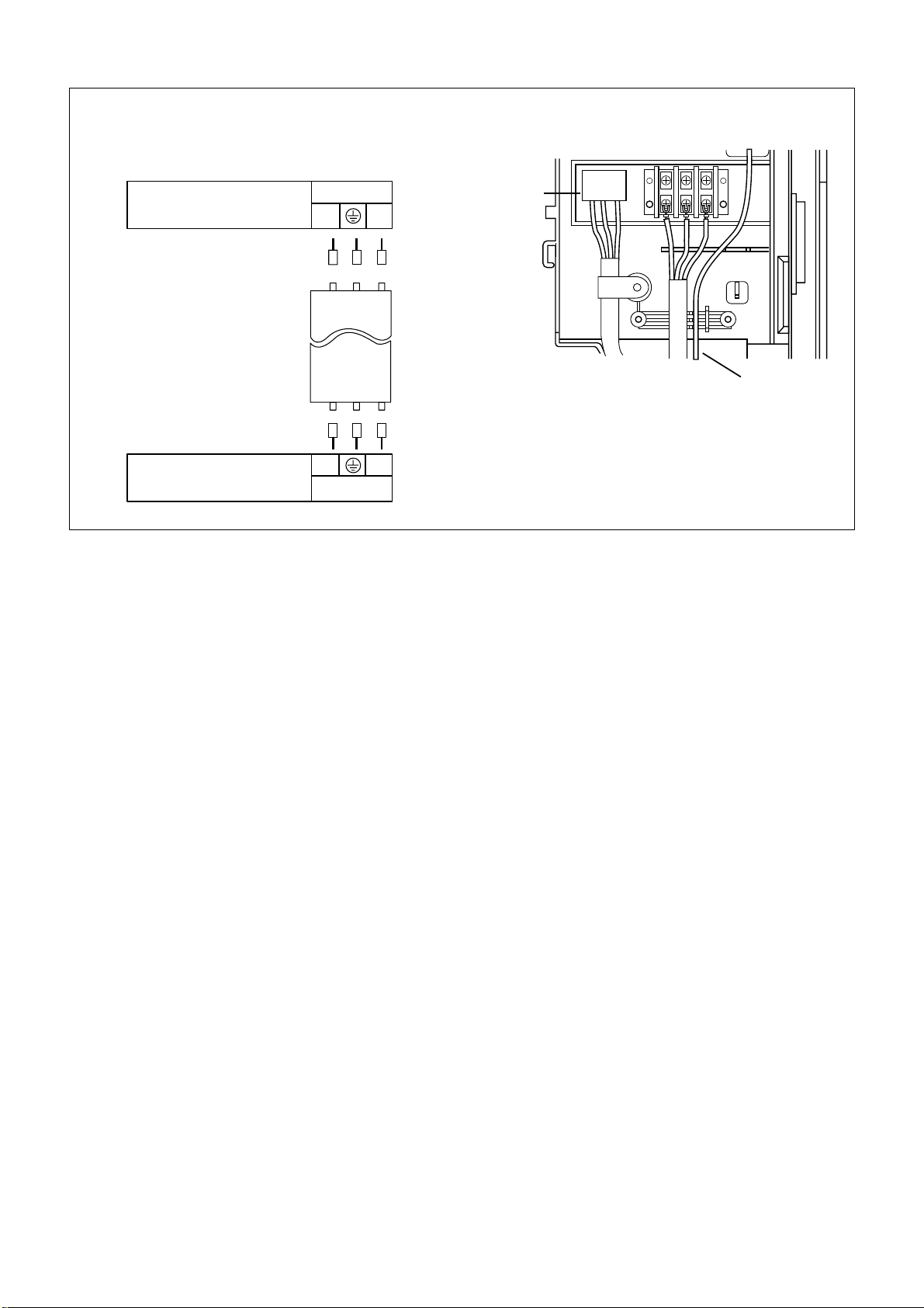
4. Connect the wires to the housing and terminals on
the control board individually according to the outdoor uint connection.
<INDOOR UNIT (Control Box)>
The used connection cable connected to indoor and
outdoor unit must be:
1) H07RN-F 3G1.5mm
2
(NOT INCLUDED)
Housing & Terminals on the
outdoor unit
color of wires
color of wires
BLACK/GRAY
BLACK/GRAY
Brown
Yellow/
Green
Brown
Yellow/
Green
Blue
Blue
Terminals
Housing & Terminals on the
indoor unit
Terminals
Terminals
Signal
++
DMB-1812LH
Y
Y
L
L
11
DMB-1812LH (9000BTU/h)
DMB-1812LH(12000BTU/h)
NOTES:
•
This appliance must be installed according to National power supply requirement.
•
If the supply cord is damaged, it must be replaced by the manufacuturer or its service agent or a similarly qualified per-
son in order to avoid a hazard.
•
Make sure the Indoor unit’s AC cord is not connected to AC power when connecting the indoor/outdoor wire.
•
When connecting wires, make sure they are fully inserted and minimum copper wire is exposed. If they are not, short-
ing, overheating, no operation, etc. may occur.
•
Be sure to comply with local codes on running a wire from the indoor to the outdoor unit.
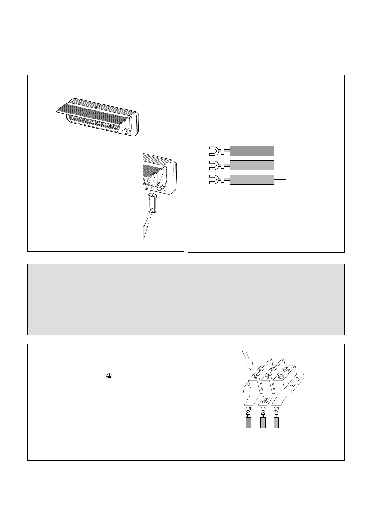
1. Open the connection cover on the indoor unit to
access the connection area.
Remove the Connection Cover.
• Loosen two screws for fixing
the Connection Cover.
• Loosen two screws at the
Connection Cover.
• Remove the Connection
Cover.
2. Fish the indoor/outdoor wire from the rear of the
indoor unit through the front of the unit.
For easier connection, make sure enough wire is
pulled through the front.
Use the wire as shown below:
Blue
Yellow/Green
Brown
The Indoor/Outdoor wire is used to supply AC from the Indoor unit to the Outdoor unit. To install the indoor/outdoor wire,
follow the procedures below.
Connection cover
Screw (Special screw)
3. To connect wires, loosen the screw in the Terminal Block
and insert the correct wires like following figure.
Connect the Brown wire to the “Y” connection,
Yellow/Green wire to the “ ”connection and the
Blue wire to “L” connection.
Y
L
Brown Blue
Yellow/Green
DMB-1812LH
(12000BTU/h)
DMB-1812LH(12000BTU/h)
12
Remove the Connection
Cover.
• Loosen the screw fixed at
the Connection Cover.
• Remove the
Connection Cover.
4. Connect the wires to the housing and terminals on
the control board individually according to the out
-
door uint connection.
<INDOOR UNIT (Control Box)>
The used connection cable connected to indoor and
outdoor unit must be:
1) H07RN-F 3G1.5mm
2
(NOT INCLUDED)
Housing & Terminals on the
outdoor unit
color of wires
color of wires
BLACK/GRAY
BLACK/GRAY
Brown
Yellow/
Green
Brown
Yellow/
Green
Blue
Blue
YL
YL
Terminals
Housing & Terminals on the
indoor unit
Terminals
Terminals
Signal
++
DMB-1812LH(12000BTU/h)
13
Left
Tubing
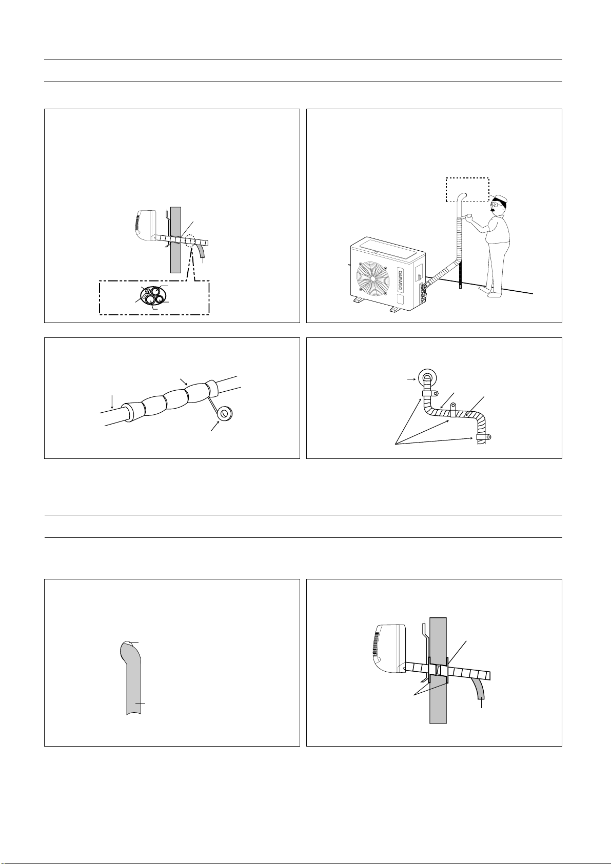
2. Make sure the drain hose and copper tubing are
wrapped with the rubber insulation. Using the tape,
wrap the indoor/outdoor wire, copper tubing and drain
hose together.
MOUNTING (INDOOR UNIT)
The Indoor unit must be mounted before connecting the indoor/outdoor wire, drain hose and copper tubing. To mount,
follow the procedures below:
1. The tubing can be extended in 4 directions as shown
below. No cutting is necessary for left/rear and
right/rear tubing connections. If using left or right tubing connections, remove the plastic area with a hacksaw so pipes can go through.
CAUTION:
•
Make sure the 12K Indoor unit’s AC cord is not
connected to AC power when performing these procedures.
• Be sure to comply with local codes on running a wire
from the indoor to the outdoor unit.
• DO NOT LET THE INDOOR/OUTDOOR WIRE
COME IN DIRECT CONTACT WITH THE TUBING
OR HOSE!
3. Shape the tubing so it can easily go through the hole
in the wall. Push the indoor/outdoor wire, copper tubing and drain hose through the hole in the wall angling
downward. Situate the indoor unit on the wall bracket
by lifting the indoor unit slightly above the wall bracket
and then down so it is securely locked in place.
Wall Bracket
Insert Putty
Drain Hose
CAUTION:
• When using the tube reamer, hold the tube downward and make sure no copper scraps fall into the tubing.
2. Make a flare at the end of the copper tube with a flare
tool.
Make sure the inside surface and edges are smooth
and the sides are uniform length.
1. Cut the copper tube extension to the desired length
with a tube cutter. It is highly recommended that 1 foot
is added to the requested length. After cutting, deburring may be necessary (see below diagram). Perform
this with a tube reamer.
BEFORE AFTER
PREPARING THE COPPER TUBING (NOT INCLUDED)
A copper tubing extension (not included) may need to be cut. If this is the case, it will also have to be deburred and
flared as shown below:
Flare tool
Flare nut
Connection
pipe
Right
Tubing
Right/Rear
Tubing
Left/Rear
Tubing
14
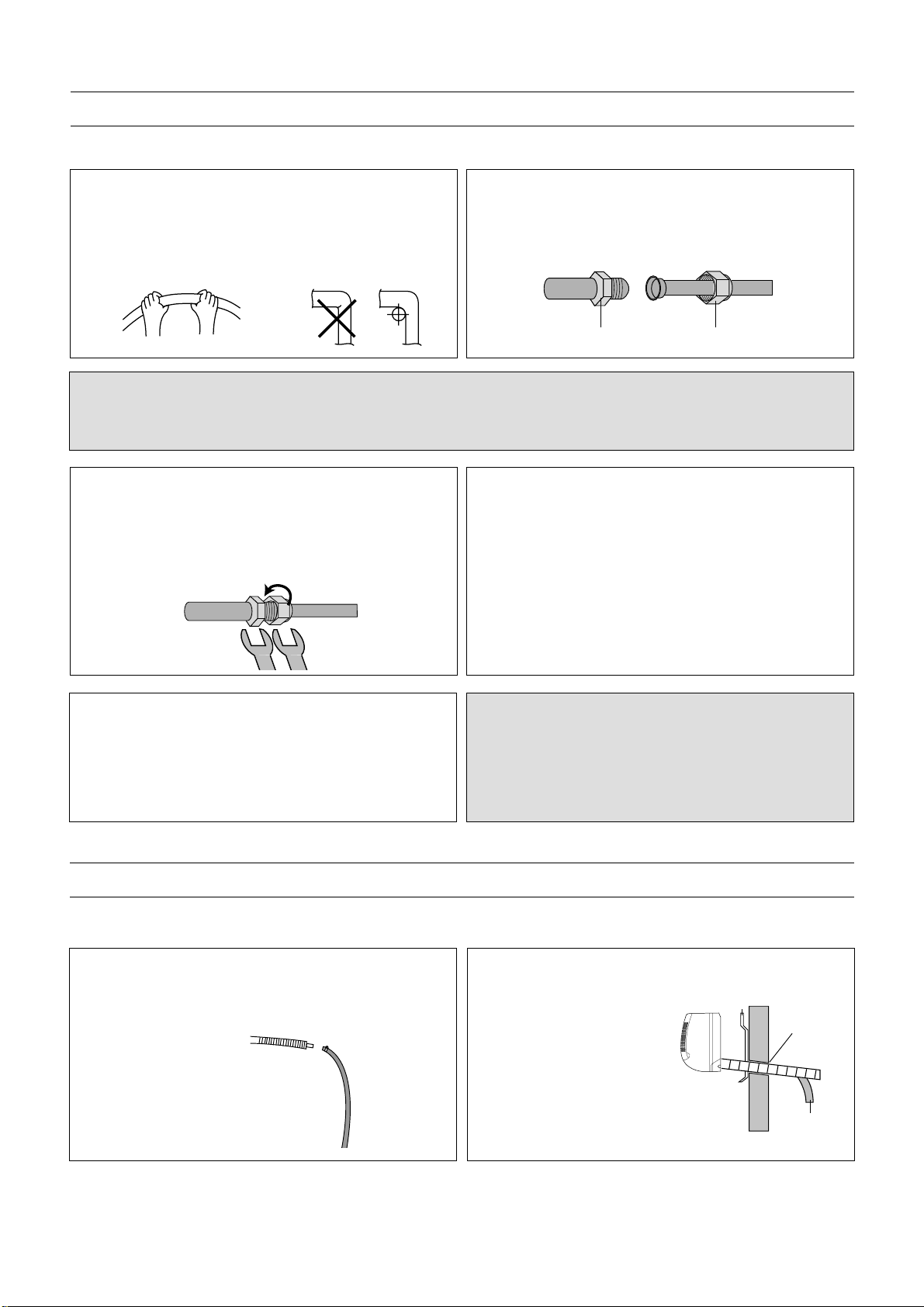
1. Remove the flare nut stoppers from the inside unit.
Determine the location of the copper tubing and
where the bends will be. Gently bend the copper tubing, making sure to use big angles so no crimping will
occur. Try to do this on the first try as repeated bending may break or crimp the tubing.
2. Remove the plastic stoppers from the tubing. Connect
the large and small copper tubing to the respective
extension and rotate the flare nut with your finger until
a smooth match is made. Make sure the copper
extension has foam rubber (insulation) on it.
Flare Nutcoupler
CONNECTING COPPER TUBES
To connect the copper tubes, follow the procedures below:
NOTE:
When removing the flare nut stopper from the inside unit, confirm “Ping”, sounds because the mixed gas is charged in
the inside unit,
3. Once a smooth match is made, tighten the flare nut
using a wrench. Be very careful not to strip the
threads or flare nut. Repeat this process for the small
and large tubing. When tightening the flare nut, use
another wrench to securely hold the coupler from
twisting and possibly damaging the tubing.
4. Remove the flare nut stoppers from the outdoor unit’s
valves. Connect the larger copper tubing to the larger
valve on the outdoor unit. Connect the smaller copper
tubing to the smaller valve on the outdoor unit.
5. Perform a leak test on all copper tube connections. To
prevent heat loss and damage to walls from condensation, the copper tube connections coming from the
wall must be insulated. Do this by wrapping foam rubber or equivalent around the connection approximately 8mm thick so no copper tubing is exposed.
NOTES:
• As with all wiring and hookups on this unit, make sure
the AC plug on the 12K indoor unit is unplugged.
• Be very careful not to strip the threads or flare nut.
• When insulating the connections, use foam rubber or
equivalent.
1. Connect the drain hose extension to the drain hose
coming from the indoor unit by loosing the clamp on
the extension using a phillips screwdriver, attaching
the hoses together and then tightening the clamp.
2. Run the drain hose, slanted downward, outside. If the
drain pipe is exposed
indoors, make sure it is
thoroughly insulated so
condensation does not
ruin walls or furniture or
come in contact with the
AC connection or extension. Also, do not crease
or form a trap in the tubing.
Wall Bracket
Insert Putty
Drain Hose
CONNECTING THE DRAIN HOSE
To connect the drain hose, follow the procedures below:
15
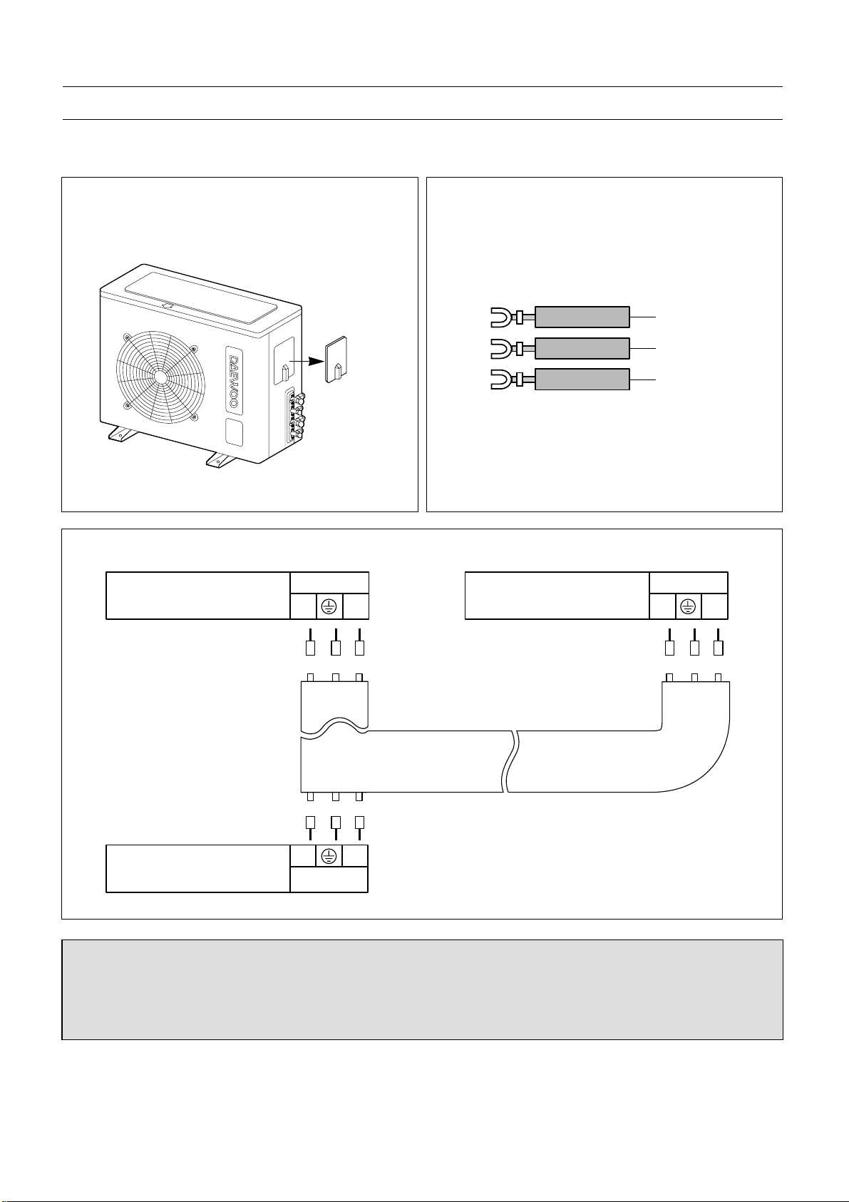
1. Remove the screw holding on the connection cover.
Remove the connection cover on the outdoor unit to
access the connection area.
3. Connect the wires to the housing and terminals on the control board individually as the following.
INSTALLING THE INDOOR/OUTDOOR WIRE T O THE OUTDOOR UNIT FOR AC CONNECTION
The Indoor/Outdoor wire is used to supply AC from the Indoor unit to the Outdoor unit. To install the indoor/outdoor wire,
follow the procedures below.
2. Route the indoor/outdoor wire into the opening on the
outdoor unit and through the wire holder. To connect
to the wire holder, loosen the screw on the wire holder, insert the wires through, then tighten the screw.
NOTES:
• Make sure the Indoor unit’s AC cord is not connected to AC power when connecting the indoor/outdoor wire.
• When connecting wires, make sure they are fully inserted and minimum copper wire is exposed. If they are not,
shorting, overheating, no operation, etc. may occur.
• Be sure to comply with local codes on running a wire from the indoor to the outdoor unit.
Yellow/Gre
Blue
Brown
Housing & Terminals on the
outdoor unit
color of wires
color of wires
BlueBrown
Yellow/
Green
BlueBrown
Yellow/
Green
YL
YL
Terminals
Housing & Terminals on the
indoor unit (9K)
Housing & Terminals on the
indoor unit (12K)
Terminals
BLACK/GRAY
BLACK/GRAY
color of wires
BlueBrown
Yellow/
Green
YL
Terminals
DMB-1812LH
Connection
Cover
16
4. To connect wires, loosen the screw in the Terminal
Block and insert the correct wires like following figure.
Connect the Blue wire to “L” connection, Brown wire
to the “Y” connection, the Yellow Green wire to the
“” connection
The used connection cable connected to indoor and
outdoor unit must be ;
1) H07RN-F 3G 1.5mm
2
X2 (NOT INCLUDED)
Y
L
<OUTDOOR UNIT (Control Panel)>
DMB-1812LH
9K White
Signal
12K Red
17
1. Tape the two copper tubes, drain hose (and the
electrical wiring if local codes permit) together with
the supplied tape. Make sure the electrical wiring
does not come in direct contact with the copper tubing or drain hose. Approximately 1 foot outside the
hole, let the drain hose out and separate from the
copper tubing and wiring.
Wall braket
Introduceti chit
Drain hose
2. Begin wrapping from the point the tubing comes out of
the outdoor unit and continue to the hole in the wall.
Leave no gaps or breaks and cover the entire length
of the tubing. As you wrap, overlap the previous turn
by half the width of the tape.
TAPING UP THE WIRE/TUBES/HOSE
After running the wire, hose and tubing outside, tape them up as shown below to insulate.
1. Apply the putty to any area on the outside hole that air
or rain can get into.
Apply Putty
Here
Tubing
2. After applying putty, insert the wall Cap at Indoor side
and Outdoor side.
Wall Bracket
Insert Putty
Wall Cap
(For DS-110R)
Drain Hose
APPLYING PUTTY AND INSERTING WALL CAP
After running the wires and tubing outside, putty should be inserted around the opening on the outside to protect against
rain, wind, etc. To apply putty, see below:
Indoor side Wall
Outdoor side
3. Wrap the piping joints with the insulator plate and fasten it with vinyl tape.
pipe
Insulator Plate
vinyl tape
4. After wrapping the connection pipe with tape, fasten it
to the outside wall with saddles, etc.
Saddle
(Not supplied)
Wall cap
Pipe
Tape
1/2" side piping
Connecting cable
Signal Wire
1/4" side piping
Drain Hose
18
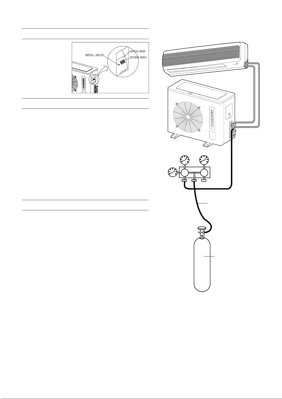
AIR PURGING
After operating the 9K and the 12K indoor units at the same time,
execute air purging or refrigerant charging.
Air and moisture remaining in the refrigerant system may create
adverse conditions as indicated below:
Before Air Purging
After connecting the power
supply, open the solenoid
valve by pressing the install
switch on the control
panel before air purging
or refrigerant charging.
• pressure in the system rises.
• operating current rises.
• cooling efficiency drops.
• moisture in the refrigerant circuit may freeze and block capil-
lary tubing.
• water may lead to corrosion of parts in the refrigerant system.
Therefore, the indoor unit and tubing between the indoor and
outdoor unit must be evacuated to remove moisture from the system.
After air puring or refrigerant charging, turn the install switch off.
AIR PURGING WITH VACUUM PUMP (TEST R UN)
Confirm each tube (narrow and wide tubes) between the indoor
and outdoor units has been properly connected and all wiring
for the test run has been completed. Remove the valve caps
from the wide and narrow service valves on the outdoor unit.
Note that both narrow and wide tube service valves on the outdoor unit are kept closed at this stage (shipping position).
Leak Test
1. With the service valves on the outdoor unit remaining closed,
remove the threaded cover on the wide tube service port.
(Save for reuse.)
2. Attach a manifold valve (with pressure gauge) and dry nitrogen gas cylinder to this service port with charge hoses.
CAUTION:
Be sure to use a manifold valve for air purging. If it is not avail
-
able, use a stop valve for this purpose. The “Hi” knob of the
manifold valve must always be kept closed.
3. Pressurize the system to no more than 150 P.S.I.G. with dry
nitrogen gas and close the cylinder valve when the gauge
reading reaches 150 P.S.I.G. Next, test for leaks with liquid
soap.
Lo Hi
Pressure
Gauge
Manifold Valve
Outdoor Unit
Indoor Unit
Charge Hose
Nitrogen Gas
Cylinder
(Vertical
Position)
19
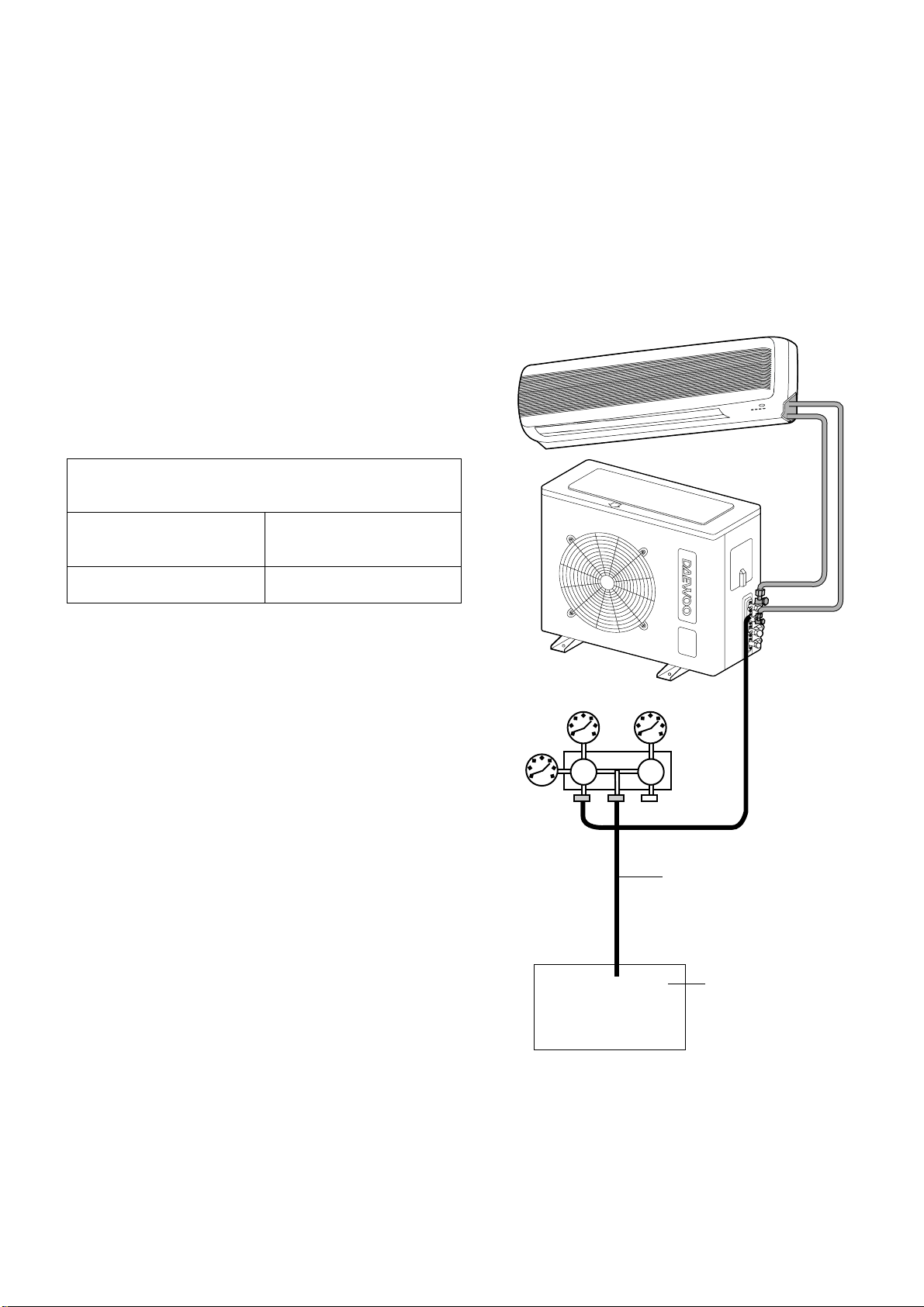
Evacuation
1. Attach the charge hose end described in the leak test
area to a vacuum pump to evacuate the air remaining
at the tubing and indoor unit.
Confirm the “Lo” knob of the manifold valve is open.
Then, run the vacuum pump. The operation time for
evacuation varies with the tubing length and capacity of
the pump. The following table shows the amount of
time for evacuation:
2. When the desired vacuum is reached, close the “Lo” knob
of the manifold valve and stop the vacuum pump.
Finishing the job
1. With a hex wrench, turn the narrow tube service valve
stem counter-clockwise to fully open the valve.
2. Turn the wide tube service valve stem counter-clockwise
to fully open the valve.
To avoid gas from leaking when removing the charge hose,
make sure the wide tube service valve is fully open and
turned all the way out.
3. Loosen the charge hose connected to the wide tube service port slightly to release the pressure, then remove the
hose.
4. Replace the threaded cover on the wide tube service port
and fasten it securely. This process is very important to
prevent gas from leaking from the system.
5. Replace the valve caps at both wide and narrow service
valves and fasten them securely.
This completes air purging with a vacuum pump. The air
conditioner is now ready to test run..
If tubing length is less than
33 ft. (10 m)
10 min. or more
If tubing length is longer than
33 ft. (10 m)
15 min. or more
Required time for evacuation when 30 gal/h vacuum
pump is used
Lo Hi
Pressure
Gauge
Manifold Valve
Outdoor Unit
Indoor Unit
Charge Hose
Vacuum
Pump
CAUTION:
CAUTION:
To avoid nitrogen entering the refrigerant system in a liquid
state, the top of the nitrogen gas cylinder must be higher than its bottom when you pressurize the system. Usually, the
cylinder is used in a vertical standing position.
4. Do a leak test of all joints of the tubing (both indoor and outdoor) and both wide and narrow service valves. Bubbles
indicate a leak. Be sure to wipe off the soap with a clean cloth.
5. After the system is found to be free of leaks, relieve the nitrogen pressure by loosening the charge hose connector at
the nitrogen cylinder. When the system pressure is reduced to normal, disconnect the hose from the cylinder.
20
TEST RUN
Check that all tubing and wiring have been completed correctly. Check again that the wide and narrow tube service
valves are fully opened. Turn on the power and run the system.
Service Valve Construction
• Valve Position Closed
The valve systems of both the wide and narrow tubes are turned all the way in. The unit is shipped from the factory in
this position and it is also used for Pump Down and Air Purging.
• Valve Position Fully Open
The valve stems of both the wide and narrow tubes are turned all the way out. This is normal operating and Test Run
position.
• Valve Position Half Open
With the narrow tube valve stem is turned to the halfway-down position. This position is used for pressure measurement and gas charging.
CAUTION:
When opening or closing the service valve stem, be sure to use a hex wrench.
PUMP DOWN
Pump Down means collecting all refrigerant in the outdoor unit without loss in refrigerant gas.
This is performed when the unit is to be relocated or the refrigerant circuit is serviced.
CAUTION:
Be sure to perform Pump Down procedure with the unit cooling mode.
Pump Down Procedure (execute the pump down of the 12K and 9K respectively)
1. Connect a low-pressure gauge manifold hose to the charge port on the wide tube service valve.
2. Open the wide tube service valve halfway and purge the air from the manifold hose using the refrigerant gas.
3. Close the narrow tube service valve (all the way in).
4. Turn on the unit’s operating switch and start the cooling operation.
5. When the low-pressure gauge reading becomes 1 to 0.5 kg/cm2 (14.2 to 7.1 psi), fully close the wide tube valve stem
and then quickly turn off the unit. At that time, Pump Down has been completed and all refrigerant gas will have been
collected in the outdoor unit.
21
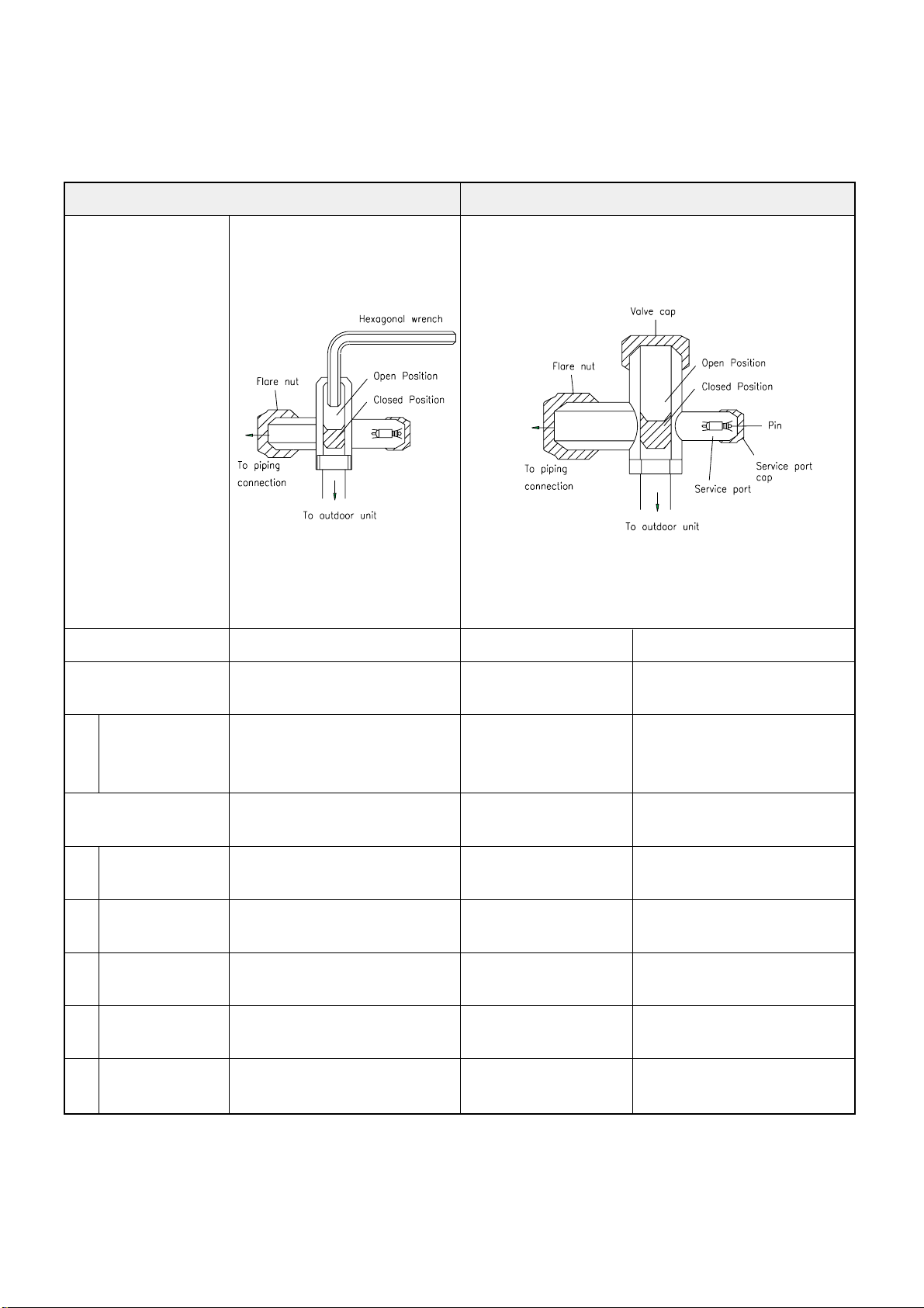
3-Way Valve
22
3-way valve(Liquid Side) 3-way valve(Gas Side)
Works Shaft position Shaft position Service port
Shipping Closed Closed Closed
(with valve cap) (with valve cap) (with cap)
1 Air purging Open Closed Open
(Installation) (counter-cloc kwise) (cloc kwise) (push-pin or with
vacuum pump)
Operation Open Open Closed
(with valve cap) (with valve cap) (with cap)
2 Pumping down Closed Open Open (connected
(Transfering) (clockwise) (counter-clockwise) manifold gauge)
3 Evacuation Open Open Open
(Servicing) (with charging cylinder)
4 Gas charging Open Open Open
(Servicing) (with charging cylinder)
5 Pressure check Open Open Open
(Servicing) (with charging cylinder)
6 Gas releasing Open Open Open
(Servicing) (with charging cylinder)
23
1
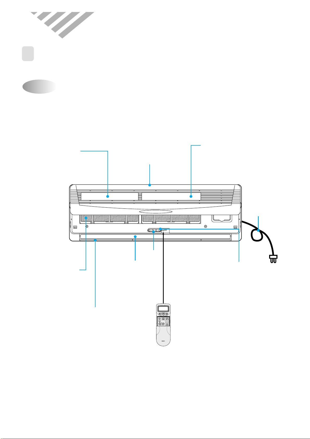
NAME AND FUNCTION OF PARTS
Indoor Unit
4. OPERA TION
DMB-1812LH(9000BTU/h)
REMOTE CONTROLLER
Electrostatic Filter
removes dust and
particles from the air
Deodorizing Filter
removes bad smells
from the air
Air Inlet
Remote
Controller
Receiver
Signal wire
Remote Controller
Fan Direction
(Up, Down)
Air Outlet
Antibacterial Filter
removes dust and
prohibits germs.
Lamp
24
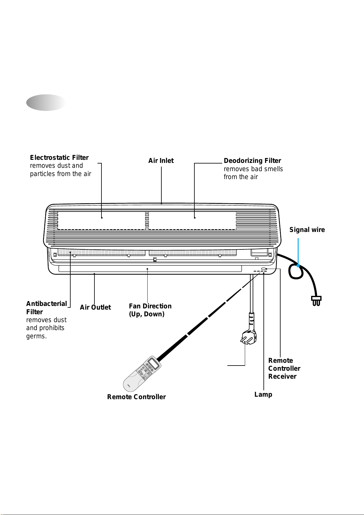
Indoor Unit
DMB-1812LH(12000BTU/h)
Power Cord
Electrostatic Filter Deodorizing FilterAir Inlet
Antibacterial
Filter
Air Outlet Fan Direction
(Up, Down)
Remote Controller
Remote
Controller
Receiver
Lamp
R
E
M
O
T
E
C
O
N
T
R
O
L
L
E
R
Electrostatic Filter
removes dust and
particles from the air
Deodorizing Filter
removes bad smells
from the air
Air Inlet
Remote
Controller
Receiver
Signal wire
Remote Controller
Fan Direction
(Up, Down)
Air Outlet
Antibacterial
Filter
removes dust
and prohibits
germs.
Lamp
25
DMB-1812LH(9000BTU/h)
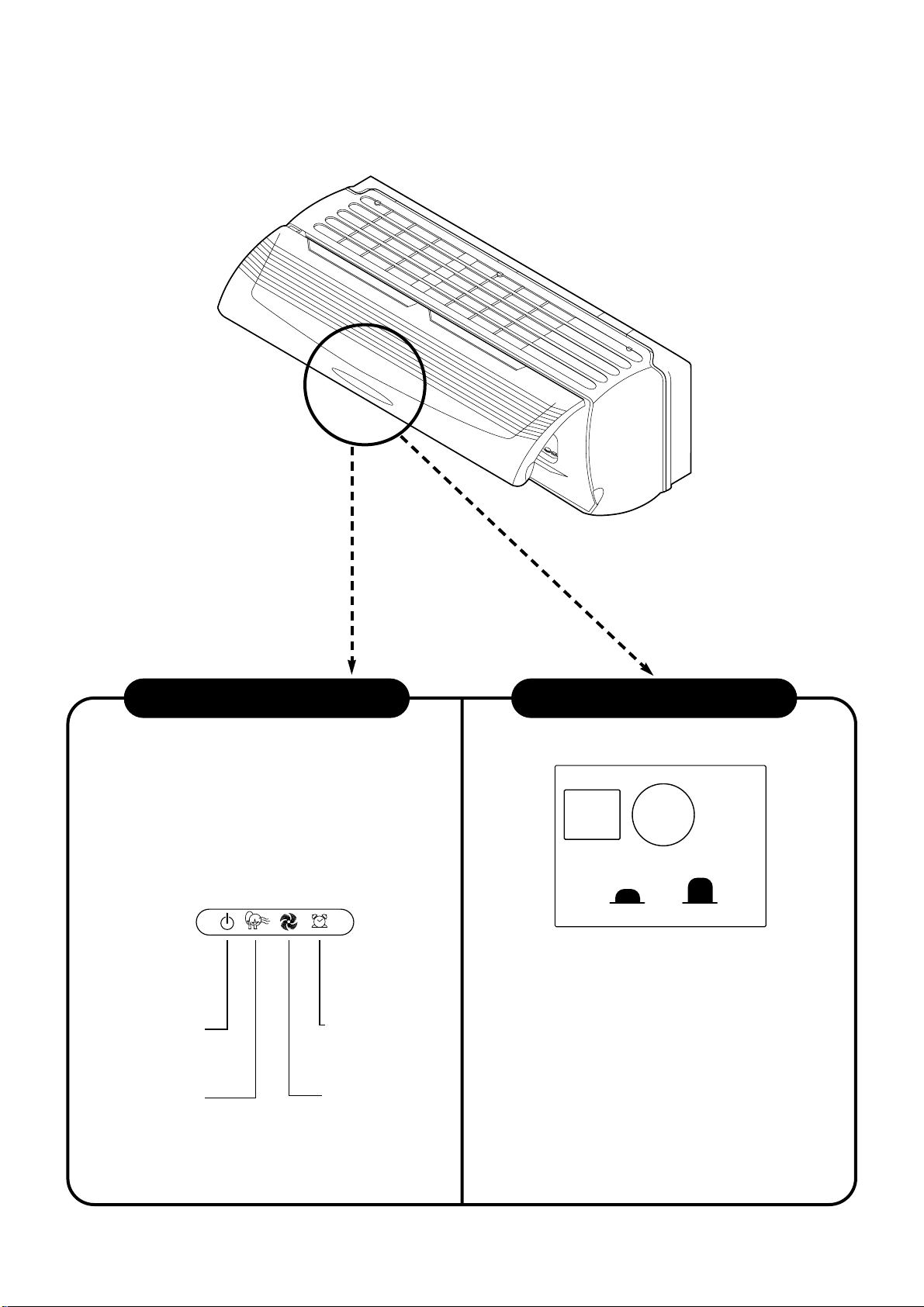
■
Remote Control Signal Receiver
This place is the part to receive the signal if it
receives the signal, you can hear the signal
“beep”.
■
When the remote controller is lost or outof-order, push the emergency button (EMR.)
to operate by hand.
Open the front panel on emergency operating.
Remocon switch is usually used with remote
controller.
Indoor Unit Display Switch Panel
Timer (Yellow)
Lights during the time
reservation mode.
Quick (Red)
ON (Red)
Lights when the
operation is going on.
Air clean (Green)
EMR. REMOCON
26
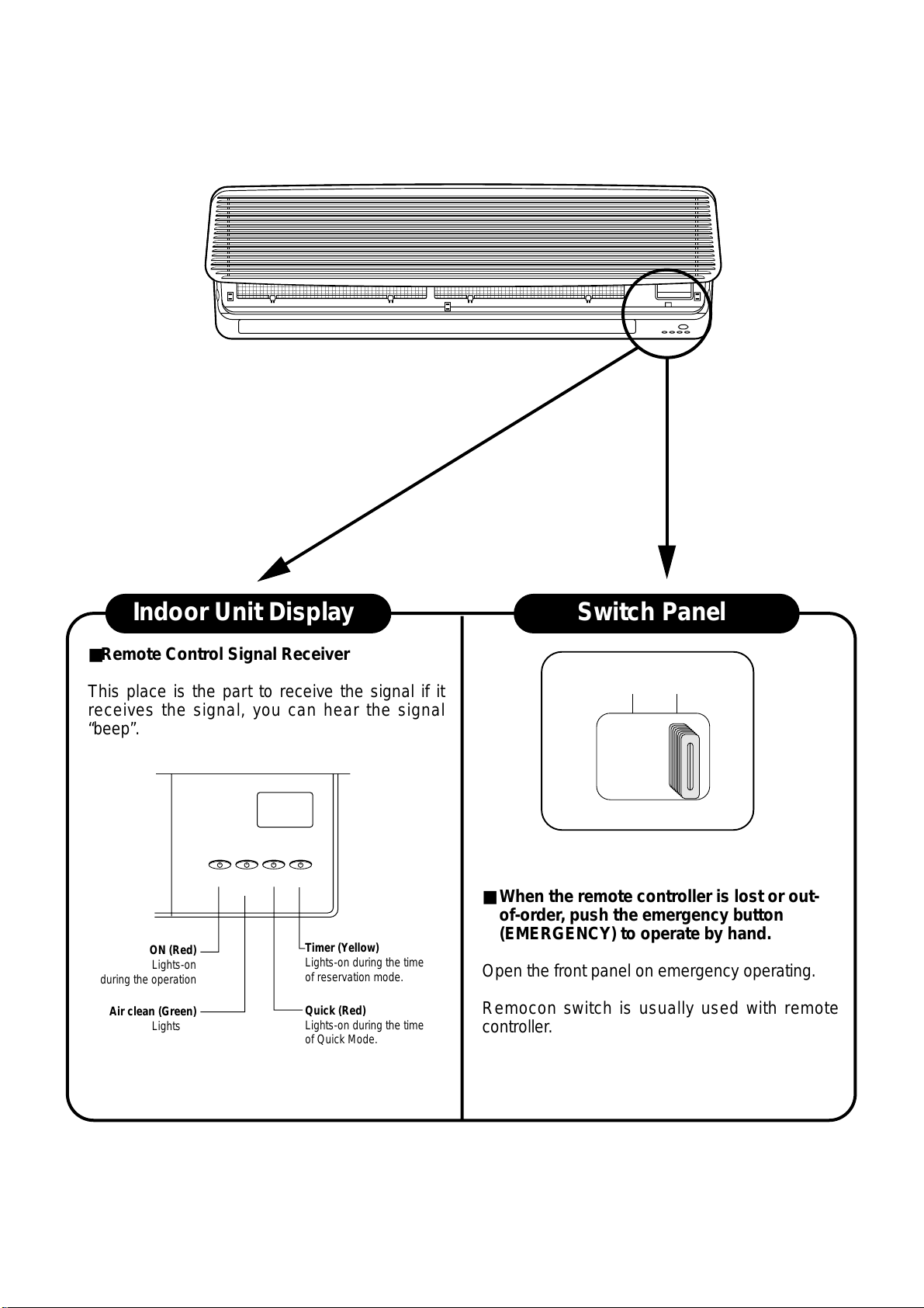
■Remote Control Signal Receiver
This place is the part to receive the signal if it
receives the signal, you can hear the signal
“beep”.
■ When the remote controller is lost or out-
of-order, push the emergency button
(EMERGENCY) to operate by hand.
Open the front panel on emergency operating.
Remocon switch is usually used with remote
controller.
Indoor Unit Display Switch Panel
Timer (Yellow)
Lights-on during the time
of reservation mode.
Quick (Red)
Lights-on during the time
of Quick Mode.
ON (Red)
Lights-on
during the operation
Air clean (Green)
Lights-on
during the operation
ON AIR
CLEAN
QUICK TIMER
EMERGENCY REMOTE
EMERGENCY REMOTE
DMB-1812LH(12000BTU/h)
27
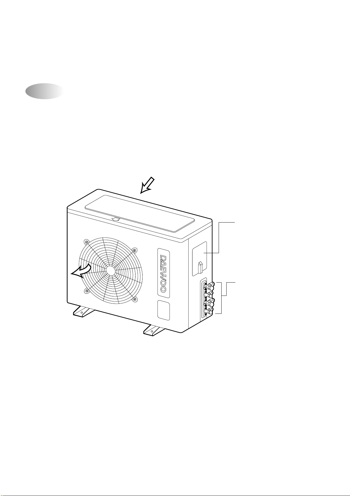
Connection Cover
Remove cover to access the
AC connection to the indoor unit.
Service Valves
The indoor and outdoor units
are connected by copper tubes
which are connected here.
AIR IN
AIR OUT
Outdoor Unit
28
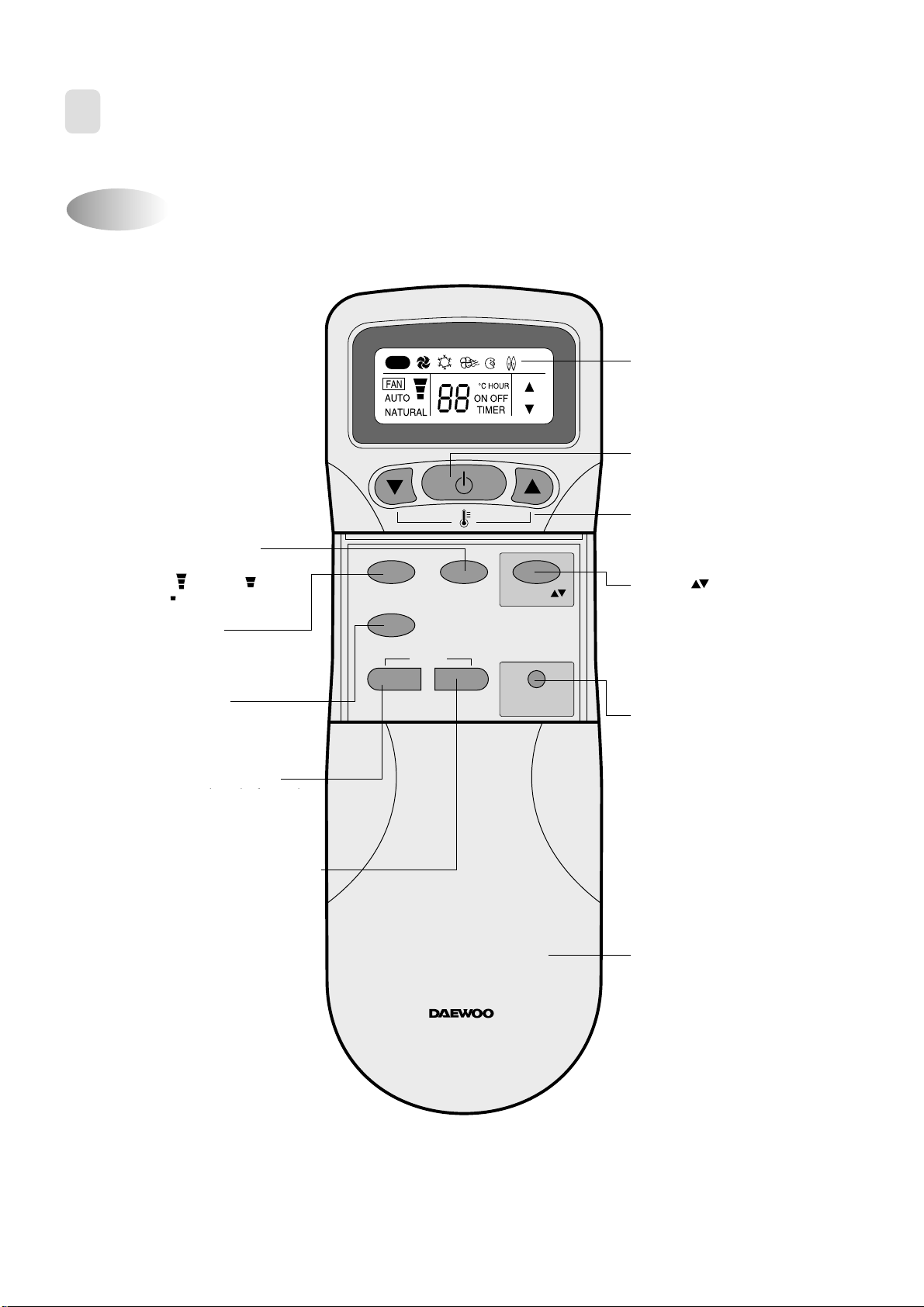
Name of Each Button
2
REMOTE CONTROLLER
MODE
SLEEP
ON/OFF
TIMER
ENTER/
CANCEL
FAN SPEED
TURBO/MILD
Display
Displays information
pertaining to unit.
TURBO/MILD
Press to be colder the unit.
TIMER ENTER/CANCEL Button
Press to enter a timer setting or
to cancel timer setting
TIMER ON/OFF Button
Press to set the unit of or on time.
(0.5, 1, 1.5, 2, 2.5, 3, 4, 5, 6, 8,
10, 12, 16, 20, 24hr)
MODE Button
Press to cycle through the modes
(Auto/Quick/Cooling/Fan/Dry)
SLEEP Button
Press to set the unit for
the sleep mode.
FAN DIR.
FAN DIR. Button
Press to select up/down
direction for fan.
ON/OFF Button
Press to turn the unit
on or off.
TEMPERATURE Buttons
Press to raise or lower
the desired temperature.
FAN SPEED Button
Press to select the fan speed
(High " ", Middle " ",
Low " ").
COVER
Slide down to access most
of the remote buttons.
Slide down further to
access the battery
compartment.
AUTO
REMOTE CONTROLLER
Press to set the unit off or on time.
(0.5, 1, 1.5, 2, 2.5, 3, 4, 5, 6, 8, 8,
10, 12, 16, 20, 24hr)
Timer O/OFF Button
29
Replacing Batteries
3
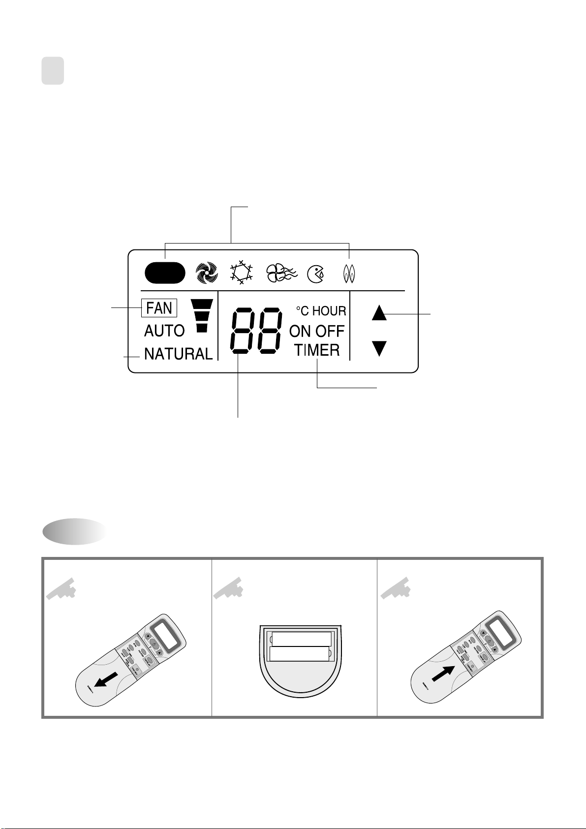
REMOTE CONTROLLER DISPLAY
Open the cover after
pressing the arrow
direction and pulling out.
Put the dry cell by "+", "-"
direction.
Close the cover after
pushing into arrow
direction.
1
2
3
R
E
M
O
T
E
C
O
N
T
R
O
L
L
E
R
+–
+–
R
E
M
O
T
E
C
O
N
T
R
O
L
L
E
R
MODE Indicators (Auto/Quick/Cool/Fan/Dehumidifier/Heat)
Lights to indicate the mode selected.
TIMER Indicators (Include sleep)
Lights to indicate the timer function mode.
TEMPERATURE & RESERVATION TIME lndicator
Lights to indicate the temperature or time.
FAN DIRECTION Indicators
Lights to indicate the
fan direction.
NATURAL Indicator
Lights to indicate the
speeds simulating a breeze.
FAN Indicators
Lights to indicate
the fan speed.
AUTO
 Loading...