

Daewoo AKF-0315 Service Manual
Service Manual
Car Audio Basic, RDS & OIRT Band
S/M No : AKF0305EF1
MODEL : AKF-0305 Series
AKF-0315 Series
DAEWOO ELECTRONICS CO., LTD
http://svc.dwe.co.kr Mar. 2000
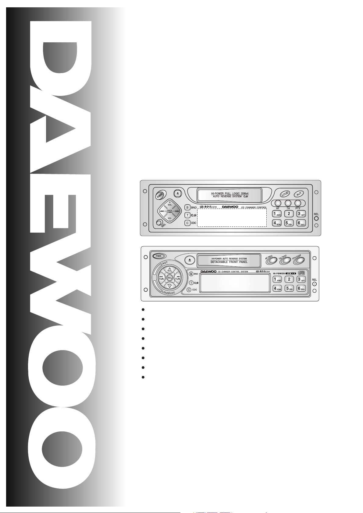
4-Channel High Power (35W x 4Ch)
Electronic Tuning
Electronic Volume/Bass/Treble/Balance/Fader Controls
Auto Memory/Preset Scan
Repeat/Random/Intro Scan
Loudness Controls
Local/DX Switch
Detachable Face for Anti-Theft

TABLE OF CONTENTS
1. PRODUCT SPECIFICATIONS .........................................1
2. LINE DRAWING ...................................................2
3. EMERGENCY TROUBLE SHOOT ...................................5
4. ADJUSTMENTS ...............................................................9
5. SCHEMATIC DIAGRAM ..................................................14
6. PARTS LOCATION ON P.C.BOARD ...........................17
7. OVERALL EXPLODED VIEW & PARTS LIST ..................23
8.
DECK MECHANISM EXPLODED VIEW & PARTS LIST
...........25
9. PARTS LIST .......................................................................28
10. FUNCTION OF MICOM IC ...............................................30
11. IC BLOCK DIAGRAM ...................................................39
12. LIQUID CRYSTAL DISPLAY .........................................46
13.
OUTPUT CONNECTION DESCRIPTIONS
..........................48

1
1. PRODUCT SPECIFICATIONS
AUDIO SECTION
Maximum output power : 35watts per channel into 4 ohms.
Load impedance : 4 ohms
Total harmonic distortion : Less than 10% at 12 watts
Frequency response : 100Hz( + 3dB), 10kHz(-5 + 3dB)
Control Bass/Treble : 10 + 3dB at 100Hz/10kHz
TAPE SECTION
Track format : 2-track / 2-channel system
Tape speed : 4.8cm/sec
Wow / Flutter : 0.35%max. (WRMS)
Frequency response normal (LH)tape : 63Hz to 10kHz
TUNER SECTION
(FM) Tuning range : 87.5 to 108MHz
87.5 to 107.9 at U.S.A
Usable Sensitivity(MONO) : 12dBuV(4
uV
/ 75ohms)
Signal to noise ratio (at 60dBu)
:
More than 50dB
(MW) Tuning range : 522 to 1620kHz at Europe
530 to 1710kHz at U.S.A
Usable Sensitivity : 30dBuV
(LW) Tuning range : 144 to 288kHz
Usable Sensitivity : 40dBuV
GENERAL
Power requirements : DC 12.0V / Rated : 14.4V
(Usable : 10.8 ~15.6V)
Negative ground
Current consumption : 10A Maximum
Dimension (W x H x D) : 178 x 50 x 156 mm
Weight(Net) : 1.75 kg
Design and specifications are subject to changes for improvements without notice.
2
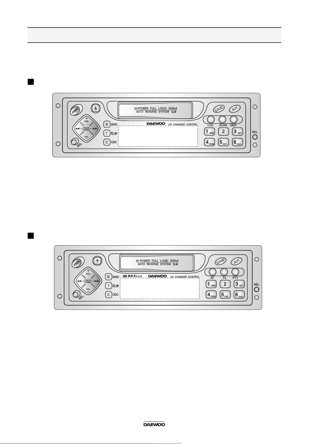
2. LINE DRAWING
2-1. AKF-0305 Front Side
BASIC
RDS
3
LINE DRAWING
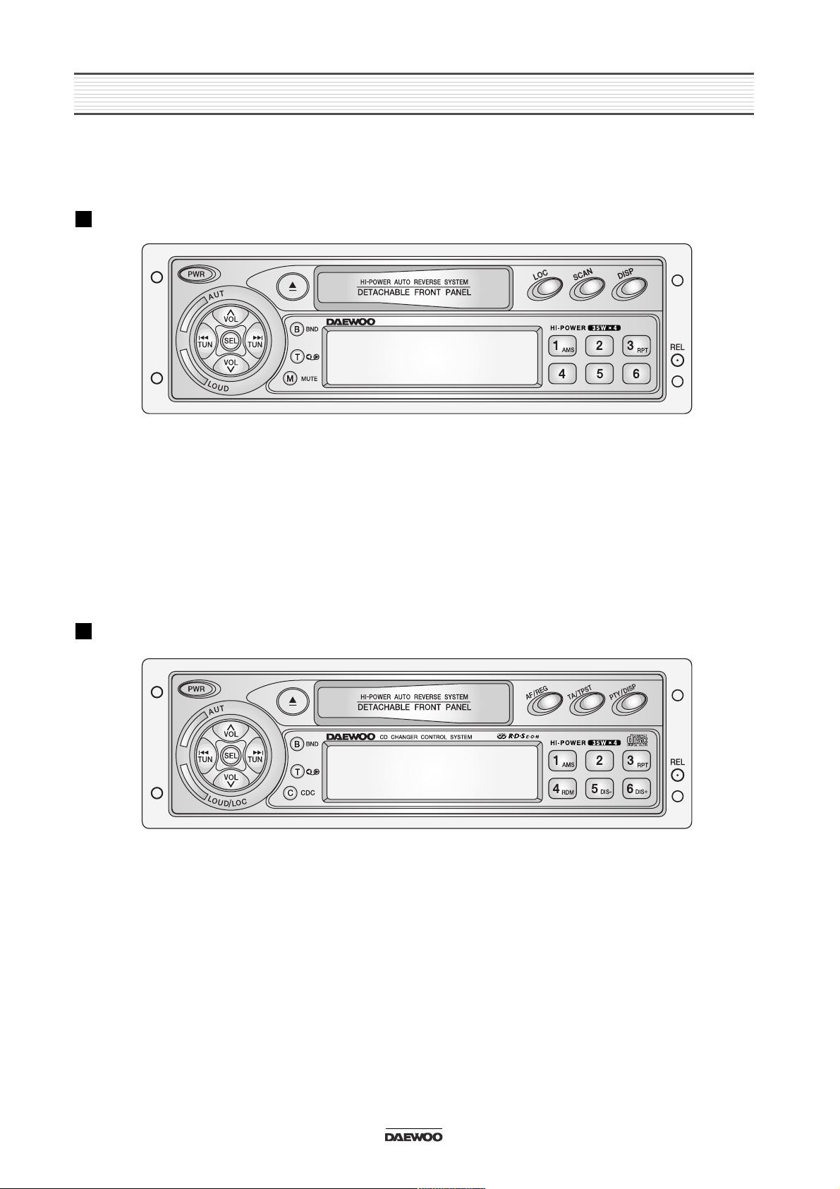
2-2. AKF-0315 Front Side
BASIC
RDS
4
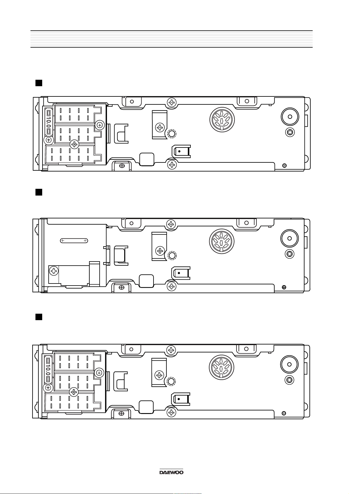
LINE DRAWING
2-3. REAR SIDE
BASIC MODEL
RDS MODEL
RDS+CD CHANGER MODEL
5
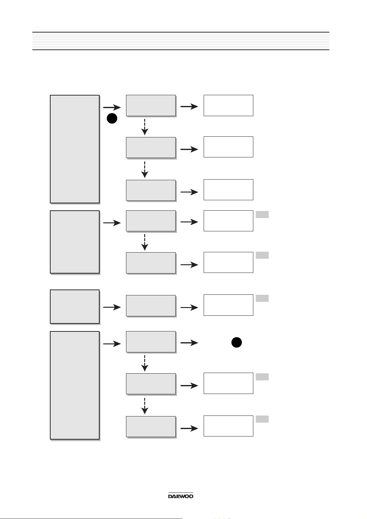
3. EMERGENCY TROUBLE SHOOT
3-1. General Function
No sound from
speakers
Yes
No
Yes
Output connector
is missing
Output connector
is inferior goods
Put exactly output
connector in.
Change output
connector to
superior goods
Yes
No
Power IC, Output
Socket is inferior
goods
Change Power IC,
Output Socket to
superior goods
Yes
A
A
L.C.D or L.E.D
is not turned
off.
Yes
No
Yes
Power is not
supplied
Ref. Point
Output voltage of
power IC is little.
Change Regulator
IC and check
output voltage.
Yes
No
LCD or LED is
inferior goods.
Change LCD or
LED to superior
goods.
Yes
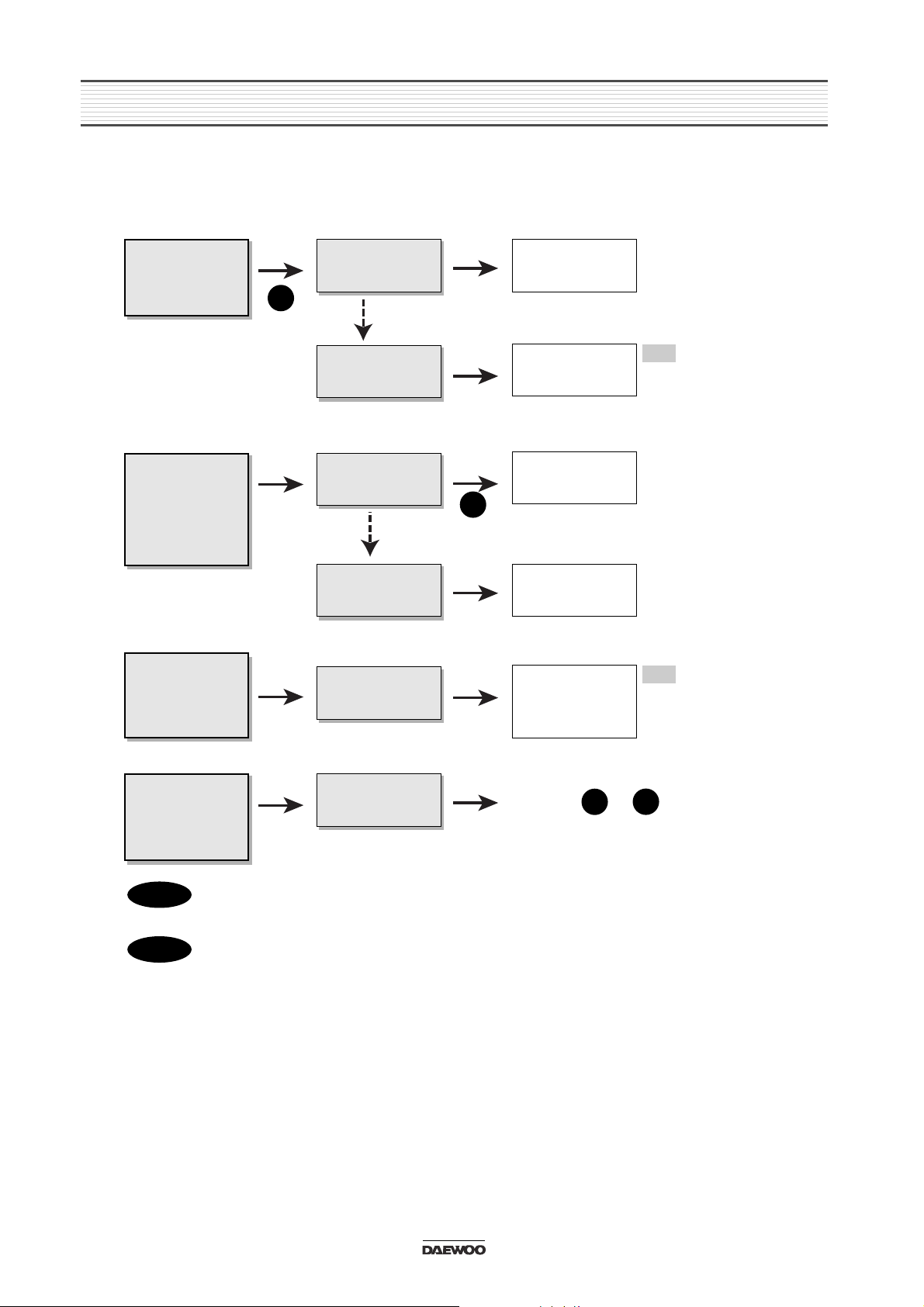
Different each
channel have
output level
(Front, Rear,
Left, Right)
Treble or Bass
is low
unusually
Yes
No
Yes
Balance of front
and rear is in one
side
Balance of Left,
Right is in one
side.
Re-adjust Balance
of front, rear
Ref.
Balance = Center
Front:00 / Rear:00
Ref.
Balance = Center
Left:00 / Right:00
Ref.
Balance = Center
Treble:00 / Bass:00
Ref.
Regulator IC output
Voltage = V
Ref.
Electrical Parts List
L.C.D., L.E.D.
Re-adjust Balance
of Left, Right
Yes
Yes
Balance of Treble
or Bass is in one
side.
Re-adjust Balance
of Treble or Bass
Yes
6
EMERGENCY TROUBLE SHOOT
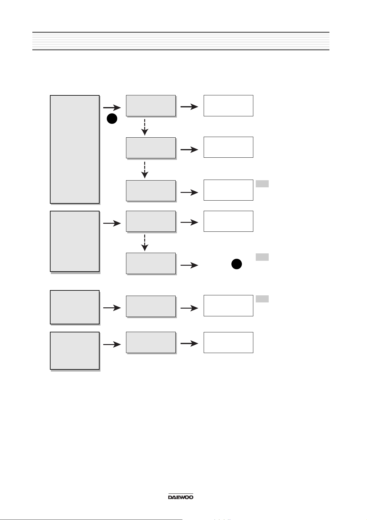
3-2. Tuner Function
Hearing noise
only
Yes
No
Yes
No selected the
station
Tuner Module is
inferior goods.
Select exactly
broadcasting
frequency.
Change tuner
module to
superior goods.
Yes
Weak frequency
area caused by
elevations
Change to goods of
R.D.S function.
Yes
A
B
A
Station in
other regions
are not held.
Yes Yes
No selected the
local stations.
Ref. Point or
Extreme noise
in broadcast
Weak
separation of
FM stereo
Yes
No
Yes
Antenna
connector is
missing
Put exactly
antenna connector
in his jack
Ref.
CAT-6, 7 etc
Electrical Parts List
Function of autoswitch noise
reduction
Ref.
Yes
Weak frequency
area of FM, AM
Switch
automatically to
mono mode in
weak frequency
area
Yes
B
R1
In case of located Glass Antenna, check if heat wire is cut or not in rear window.
R1
Check Antenna connector part.
7
EMERGENCY TROUBLE SHOOT
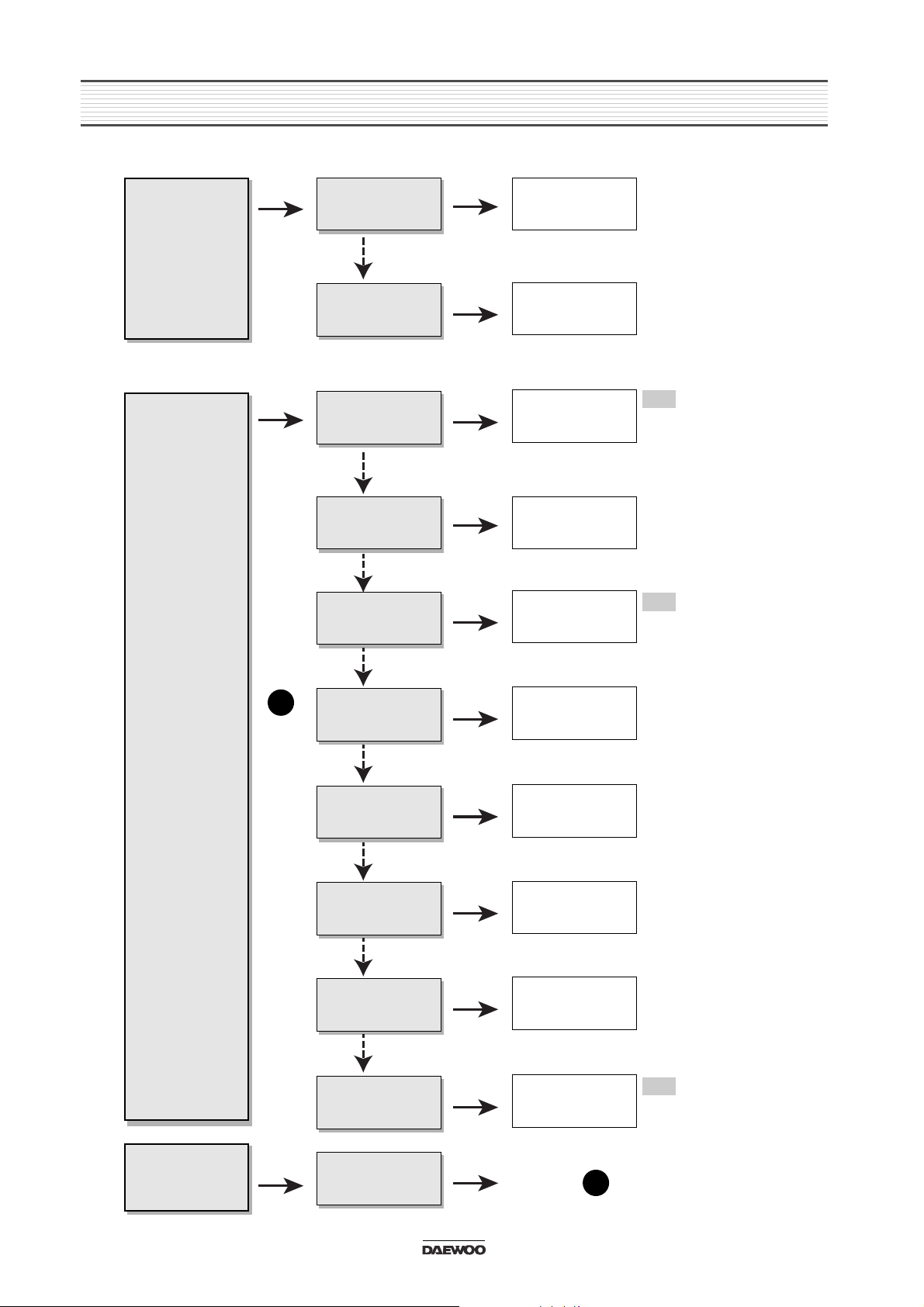
3-3. Tape Function
No sound from
speakers
Yes
No
Yes
Tape is inferior
goods
No signal play
output
Use only superior
goods
Put exactly deck
output connector
in.
Yes
No
Deck Mechanism
is inferior goods.
Change Deck
Mechanism to
superior goods.
Yes
A
A
Sound is low or
not clear
Yes Yes
Head is dirty
Ref. Point
Clean head or
pinch roller with
cleaner
Tape is not
inserted into
the slot.
Some program
is played back
repeatedly
Yes
No
Yes
Tape was inserted
right side left.
Tape is ejected
after being
inserted.
Insert recording
part to right side.
Ref.
Tape Deck Macha
ADM-21/22
Ref.
Tape is cut or
extended
Ref.
Check on L.C.D
and press RPT
button.
Yes
Yes
Selected repeat
(RPT) function.
Release RPT
function
Yes
8
EMERGENCY TROUBLE SHOOT
3-4. CDC Function
Disc is not
inserted.
Yes
No
Yes
Discs are fold in
magazine slot.
Magazine is not
inserted rightly
Put one disc in
magazine slot.
Insert exactly
magazine
Yes
Inside degree of
the unit is
extreme
Turn power off and
stop operation for
about 1 hour
No
Yes
A
Selection time
is longer than
unusually
Yes
Selected PAUSE
function
Release PAUSE
function
Yes
Selected MUTE
function
Release MUTE
function
Yes
Mechanism is
inferior goods
Change
Mechanism to
superior goods
Yes
Inspect disc for
scratches.
Yes
No sound
Yes
No
Yes
Indoor degree is
so cold
8Pin connector is
missing
Turn power on
and stand by for
about 1 hour
Ref.
protective function
is started caused by
inside degree is
extreme.
Ref.
DWEC CD-C series
AKD-60, 70, 80, 100C
Ref.
DWEC CD-C series
AKD-60, 70, 80, 100C
Put exactly CD-C
8Pin connector in.
No
No
No
No
No
Yes
Disc is inferior
goods
Change disc to
superior goods
Yes
Disc is dirty
Wipe with cleaning
cloth
Yes
A
Ref. Point
4.
ADJUSTMENTS
9
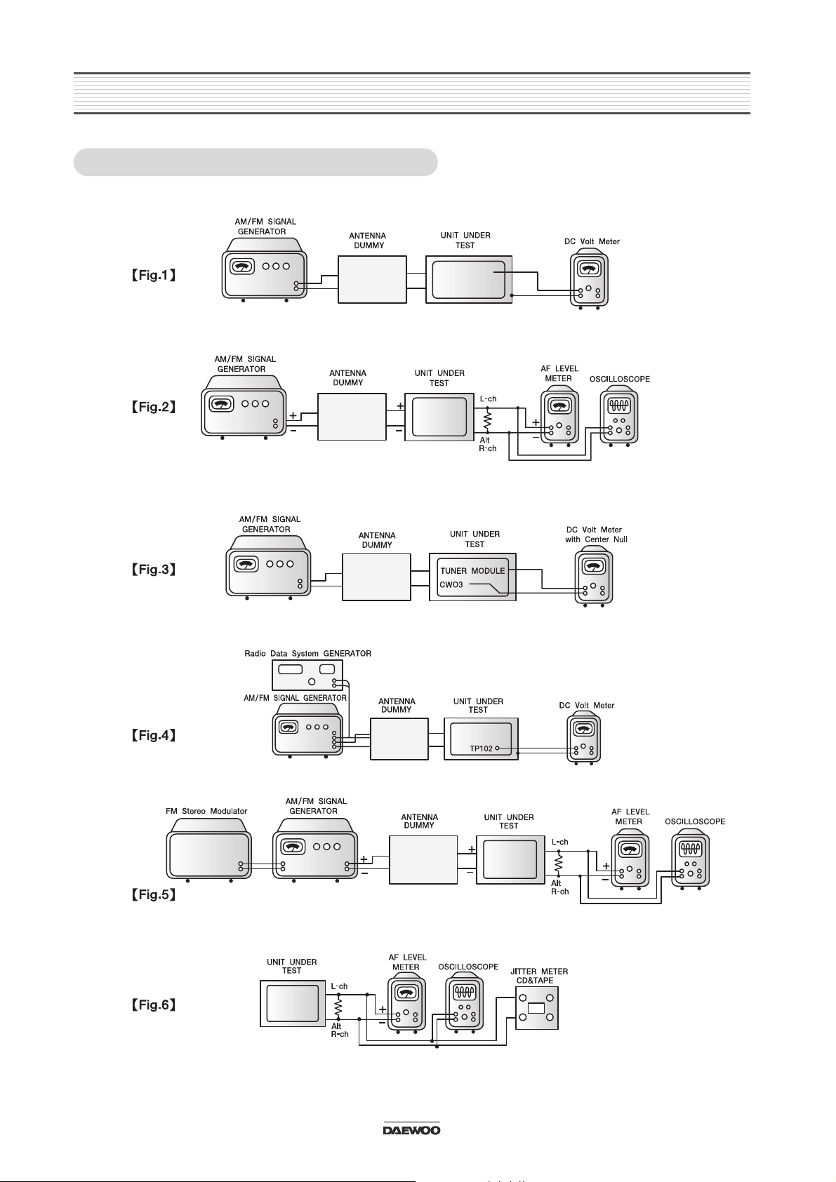
4-1. EQUIPMENTS CONNECTIONS
ADJUSTMENTS
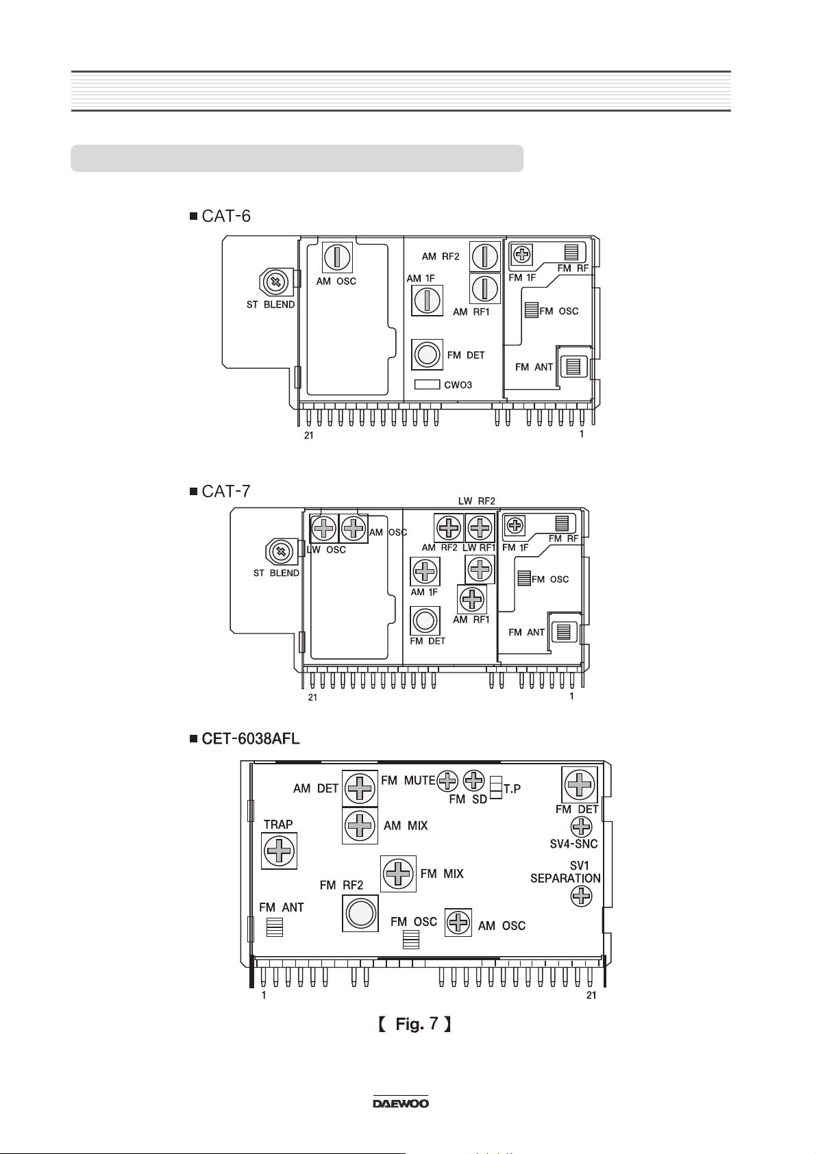
4-2. TUNER MODULE ADJUSTMENT LOCATIONS
10
ADJUSTMENTS
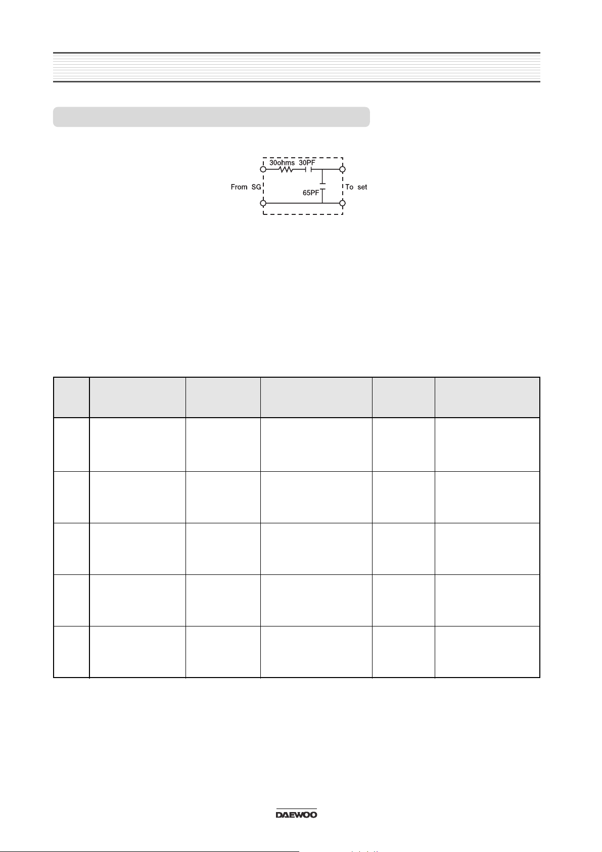
4-3. AM (MW/LW) ADJUSTMENT METHOD
11
STEP
1 Band Covering
RF-Tracking
Figure 1
Figure 2
Figure 2
Figure 1
Figure 2
522KHz 60dBu
Mod 1000Hz 30%
603KHz 30dBu
Mod 1000Hz 30%
1404KHz 30dBu
Mod 1000Hz 30%
144KHz 60dBu
Mod 1000Hz 30%
220KHz 60dBu
Mod 1000Hz 30%
522KHz
603KHz
1404KHz
144KHz
220KHz
Adjust AM OSC
for 1.2-1.35V(VT)
Fig.7
Adjust AM RF1 and
AM RF2
for maximum output
Fig.7
Adjust AM RF1 and
AM RF2
for maximum output
Fig.7
Adjust LW OSC
for 1.2-1.35V(VT)
Fig.7
Adjust LW RF1 and
LW RF2
for maximum output
Fig.7
RF-Tracking
LW Band Covering
LW-Tracking
2
3
4
5
DESCRIPTION
CONNECTION
ANTENNA SIGNAL
DIAL
CONTROL
ADJUSTMENT
1. Dummy Antenna Circuit
2. Location of Adjustment Points
Refer to Adjustment Location Page
3. Control Setting
Power Switch .................. ON Balance/Fader Control ...................... Mech. Center
Band Switch .................... AM Treble/Bass Control ........................... Mech. Center
Other ............................... OFF
4. Adjustment Procedure
NOTE: When it is U.S.A band instead of 522, 603, 999, 1404kHz is 530, 600, 1000, 1400kHz
ADJUSTMENTS
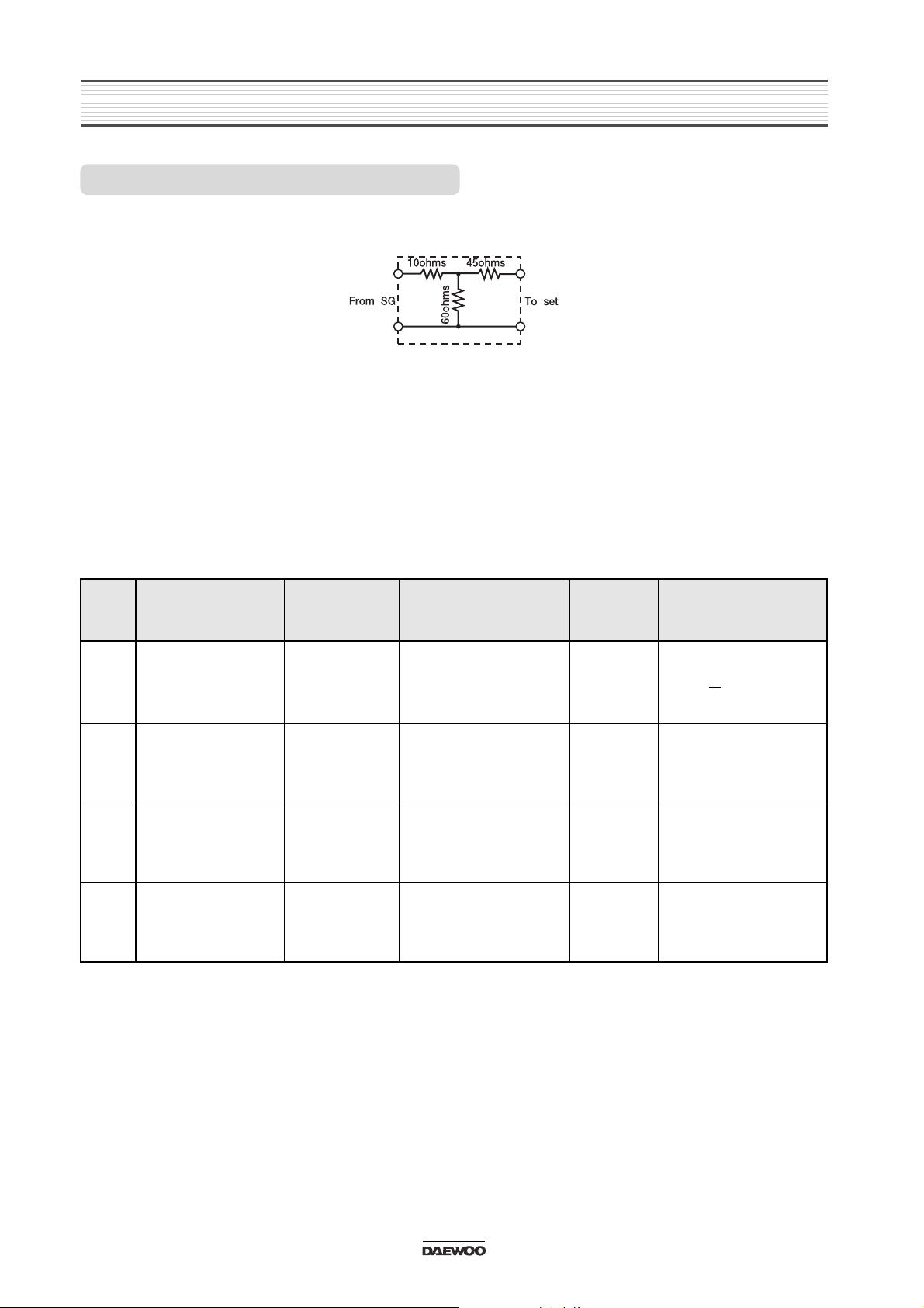
4-4. FM ADJUSTMENT METHOD
12
STEP
1 IF (Zero Volt)
RDS Receiving
estimation level
Figure 3
Figure 4
Figure 5
Figure 5
98.1MHz 60dBuV
No Modulation
98.1MHz 42dBuV
Mod.
1kHz 30% Mono
98.1MHz 60dBuV
Mod.
1kHz 30% Stereo Left
at Right ch.
98.1MHz 35dBuV
Mod.
1kHz 30% Stereo Left
at Right ch.
98.1MHz
98.1MHz
98.1MHz
98.1MHz
Adjust FM DET
for 0V + 0.03V
Fig.7
Adjust RV 108 Page7.
Tuner PC Board
for2.7V=20mV at
TP102(IC401 pin 66)
Adjust MPX SEP Fig.7
for maximum separation
Left and Right ch.
Adjust Stereo Blend
Fig.7 1dB separation
between Left and Right
ch.
Stereo Separation
SNC
4
5
6
DESCRIPTION
CONNECTION
ANTENNA SIGNAL
DIAL
CONTROL
ADJUSTMENT
1. Dummy Antenna Circuit
2. Location of Adjustment Points
Refer to Adjustment Location Page
3. Control Setting
Power Switch ................. ON Balance/Fader Control ..................... Mech. Center
Band Switch ................... FM Treble/Bass Control ......................... Mech. Center
Other ............................... OFF
4. Adjustment Procedure
ADJUSTMENTS
4-5. TAPE ADJUSTMENT METHOD
13
NOTE : 1. Clean the playback head before adjustment
2. Prepare the test tape MTT-114 or equivalent
3. Balance, Fader, Bass & Treble ....Center position. Volume adjusted to 2Volts.
Note
: dBu uV
dBu uV
17 5.0 33 44.6
16 6.31 35 56.2
30 31.6 45 178
NOTE : Antenna signal is used.
1. For Signal Generator with readings in
EMF(Open type) add 12dB (6dB for the
“Dummy” and 6dB for EMF-reading).
2. For Signal Generator with reading in dBm add 6
dB for “Dummy”
STEP
1
Head azimuth
adjustment
Tape Speed
Figure 6
Figure 6
MTT-114N
or equivalent
MTT-114N
or equivalent
Speaker
Output
Speaker
Output
Head azimuth
adjustment screw
Turn the azimuth
screw to obtain
maximum level
Adjust for 30103020Hz
Tape Speed
adjustment
2
DESCRIPTION
TEST TAPE
CONNECTION
TEST
POINT
ADJUSTMENT
POINT
ADJUSTMENT
14
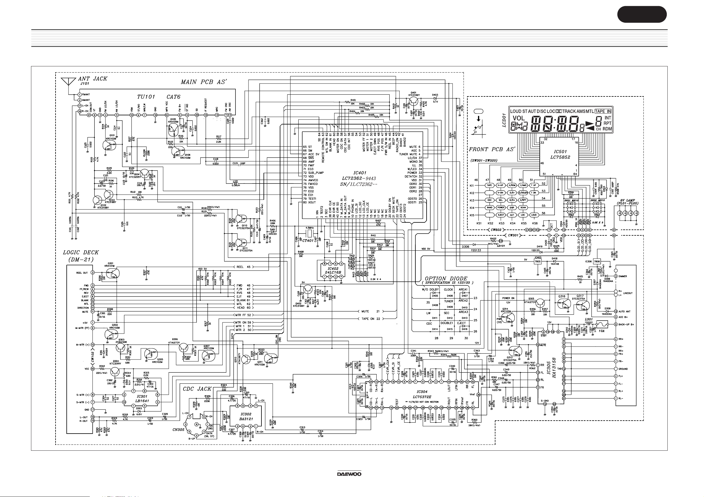
5. SCHEMATIC DIAGRAMS
5-1. BASIC Series AKF-0305 / AKF-0315
Size:A3
 Loading...