

Page 1

Service Manual
Car Audio Basic, RDS & OIRT Band
S/M No : AKF0305EF1
MODEL : AKF-0305 Series
AKF-0315 Series
DAEWOO ELECTRONICS CO., LTD
http://svc.dwe.co.kr Mar. 2000
4-Channel High Power (35W x 4Ch)
Electronic Tuning
Electronic Volume/Bass/Treble/Balance/Fader Controls
Auto Memory/Preset Scan
Repeat/Random/Intro Scan
Loudness Controls
Local/DX Switch
Detachable Face for Anti-Theft
Page 2

TABLE OF CONTENTS
1. PRODUCT SPECIFICATIONS .........................................1
2. LINE DRAWING ...................................................2
3. EMERGENCY TROUBLE SHOOT ...................................5
4. ADJUSTMENTS ...............................................................9
5. SCHEMATIC DIAGRAM ..................................................14
6. PARTS LOCATION ON P.C.BOARD ...........................17
7. OVERALL EXPLODED VIEW & PARTS LIST ..................23
8.
DECK MECHANISM EXPLODED VIEW & PARTS LIST
...........25
9. PARTS LIST .......................................................................28
10. FUNCTION OF MICOM IC ...............................................30
11. IC BLOCK DIAGRAM ...................................................39
12. LIQUID CRYSTAL DISPLAY .........................................46
13.
OUTPUT CONNECTION DESCRIPTIONS
..........................48
Page 3

1
1. PRODUCT SPECIFICATIONS
AUDIO SECTION
Maximum output power : 35watts per channel into 4 ohms.
Load impedance : 4 ohms
Total harmonic distortion : Less than 10% at 12 watts
Frequency response : 100Hz( + 3dB), 10kHz(-5 + 3dB)
Control Bass/Treble : 10 + 3dB at 100Hz/10kHz
TAPE SECTION
Track format : 2-track / 2-channel system
Tape speed : 4.8cm/sec
Wow / Flutter : 0.35%max. (WRMS)
Frequency response normal (LH)tape : 63Hz to 10kHz
TUNER SECTION
(FM) Tuning range : 87.5 to 108MHz
87.5 to 107.9 at U.S.A
Usable Sensitivity(MONO) : 12dBuV(4
uV
/ 75ohms)
Signal to noise ratio (at 60dBu)
:
More than 50dB
(MW) Tuning range : 522 to 1620kHz at Europe
530 to 1710kHz at U.S.A
Usable Sensitivity : 30dBuV
(LW) Tuning range : 144 to 288kHz
Usable Sensitivity : 40dBuV
GENERAL
Power requirements : DC 12.0V / Rated : 14.4V
(Usable : 10.8 ~15.6V)
Negative ground
Current consumption : 10A Maximum
Dimension (W x H x D) : 178 x 50 x 156 mm
Weight(Net) : 1.75 kg
Design and specifications are subject to changes for improvements without notice.
Page 4

2
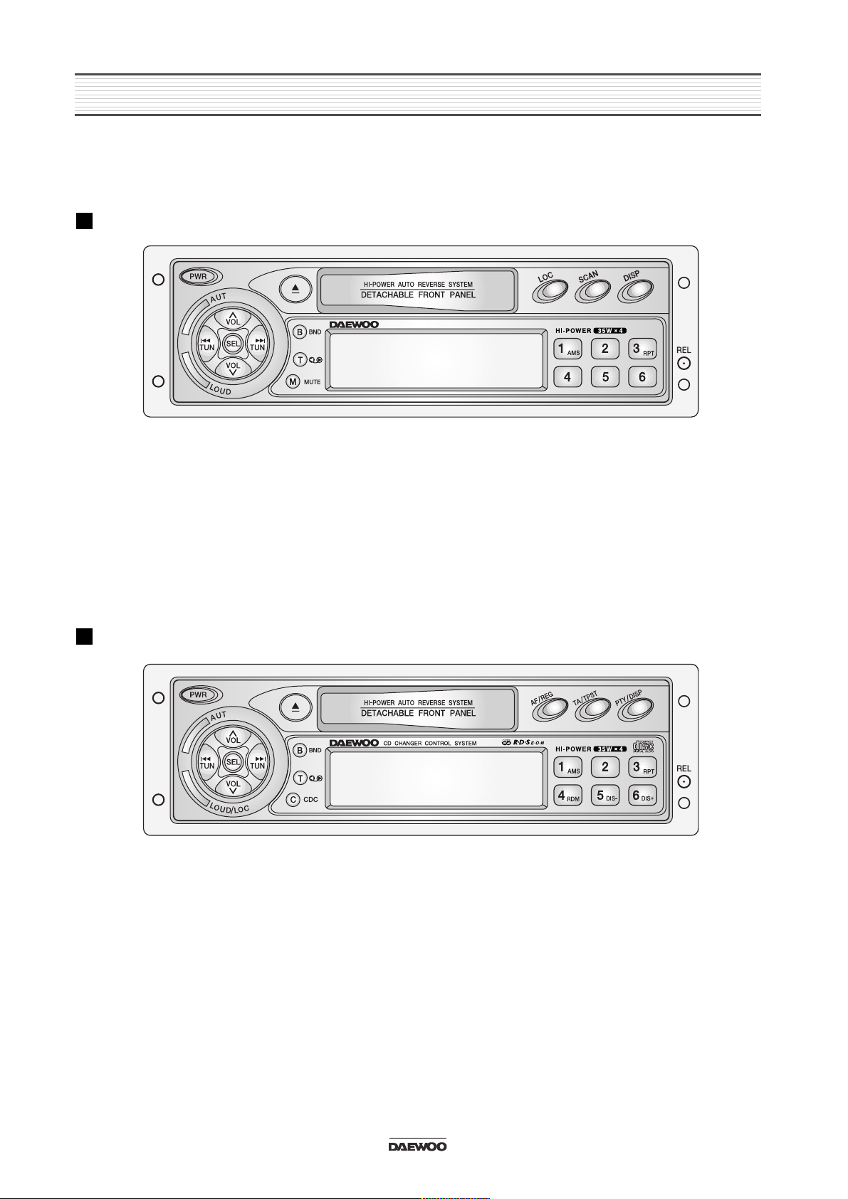
2. LINE DRAWING
2-1. AKF-0305 Front Side
BASIC
RDS
Page 5
3
LINE DRAWING
2-2. AKF-0315 Front Side
BASIC
RDS
Page 6
4
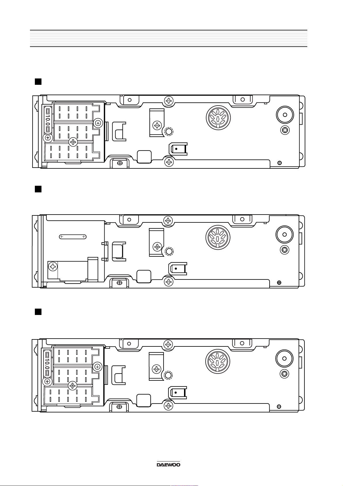
LINE DRAWING
2-3. REAR SIDE
BASIC MODEL
RDS MODEL
RDS+CD CHANGER MODEL
Page 7

5
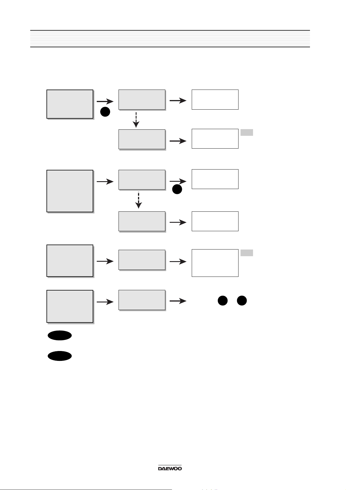
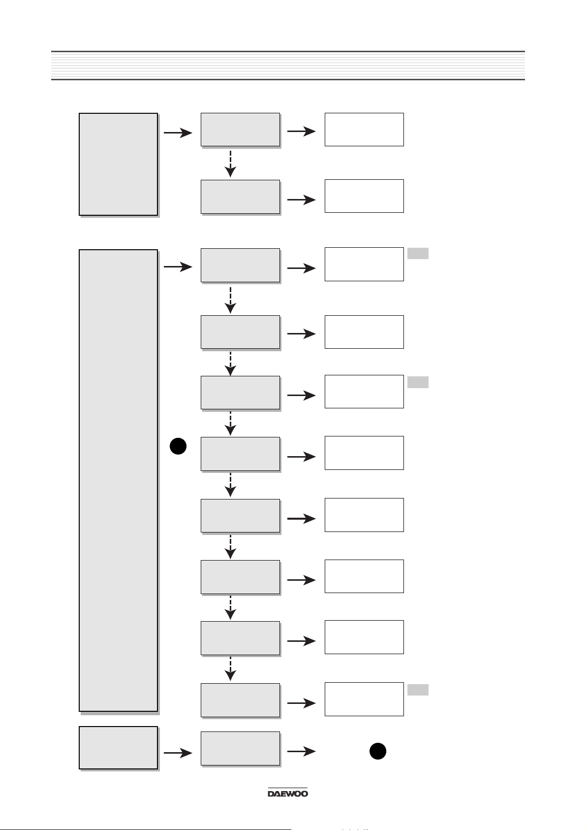
3. EMERGENCY TROUBLE SHOOT
3-1. General Function
No sound from
speakers
Yes
No
Yes
Output connector
is missing
Output connector
is inferior goods
Put exactly output
connector in.
Change output
connector to
superior goods
Yes
No
Power IC, Output
Socket is inferior
goods
Change Power IC,
Output Socket to
superior goods
Yes
A
A
L.C.D or L.E.D
is not turned
off.
Yes
No
Yes
Power is not
supplied
Ref. Point
Output voltage of
power IC is little.
Change Regulator
IC and check
output voltage.
Yes
No
LCD or LED is
inferior goods.
Change LCD or
LED to superior
goods.
Yes
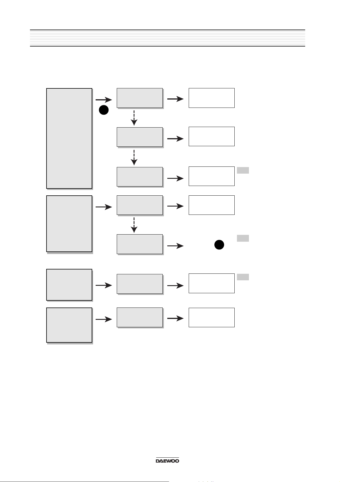
Different each
channel have
output level
(Front, Rear,
Left, Right)
Treble or Bass
is low
unusually
Yes
No
Yes
Balance of front
and rear is in one
side
Balance of Left,
Right is in one
side.
Re-adjust Balance
of front, rear
Ref.
Balance = Center
Front:00 / Rear:00
Ref.
Balance = Center
Left:00 / Right:00
Ref.
Balance = Center
Treble:00 / Bass:00
Ref.
Regulator IC output
Voltage = V
Ref.
Electrical Parts List
L.C.D., L.E.D.
Re-adjust Balance
of Left, Right
Yes
Yes
Balance of Treble
or Bass is in one
side.
Re-adjust Balance
of Treble or Bass
Yes
Page 8
6
EMERGENCY TROUBLE SHOOT
3-2. Tuner Function
Hearing noise
only
Yes
No
Yes
No selected the
station
Tuner Module is
inferior goods.
Select exactly
broadcasting
frequency.
Change tuner
module to
superior goods.
Yes
Weak frequency
area caused by
elevations
Change to goods of
R.D.S function.
Yes
A
B
A
Station in
other regions
are not held.
Yes Yes
No selected the
local stations.
Ref. Point or
Extreme noise
in broadcast
Weak
separation of
FM stereo
Yes
No
Yes
Antenna
connector is
missing
Put exactly
antenna connector
in his jack
Ref.
CAT-6, 7 etc
Electrical Parts List
Function of autoswitch noise
reduction
Ref.
Yes
Weak frequency
area of FM, AM
Switch
automatically to
mono mode in
weak frequency
area
Yes
B
R1
In case of located Glass Antenna, check if heat wire is cut or not in rear window.
R1
Check Antenna connector part.
Page 9
7
EMERGENCY TROUBLE SHOOT
3-3. Tape Function
No sound from
speakers
Yes
No
Yes
Tape is inferior
goods
No signal play
output
Use only superior
goods
Put exactly deck
output connector
in.
Yes
No
Deck Mechanism
is inferior goods.
Change Deck
Mechanism to
superior goods.
Yes
A
A
Sound is low or
not clear
Yes Yes
Head is dirty
Ref. Point
Clean head or
pinch roller with
cleaner
Tape is not
inserted into
the slot.
Some program
is played back
repeatedly
Yes
No
Yes
Tape was inserted
right side left.
Tape is ejected
after being
inserted.
Insert recording
part to right side.
Ref.
Tape Deck Macha
ADM-21/22
Ref.
Tape is cut or
extended
Ref.
Check on L.C.D
and press RPT
button.
Yes
Yes
Selected repeat
(RPT) function.
Release RPT
function
Yes
Page 10
8
EMERGENCY TROUBLE SHOOT
3-4. CDC Function
Disc is not
inserted.
Yes
No
Yes
Discs are fold in
magazine slot.
Magazine is not
inserted rightly
Put one disc in
magazine slot.
Insert exactly
magazine
Yes
Inside degree of
the unit is
extreme
Turn power off and
stop operation for
about 1 hour
No
Yes
A
Selection time
is longer than
unusually
Yes
Selected PAUSE
function
Release PAUSE
function
Yes
Selected MUTE
function
Release MUTE
function
Yes
Mechanism is
inferior goods
Change
Mechanism to
superior goods
Yes
Inspect disc for
scratches.
Yes
No sound
Yes
No
Yes
Indoor degree is
so cold
8Pin connector is
missing
Turn power on
and stand by for
about 1 hour
Ref.
protective function
is started caused by
inside degree is
extreme.
Ref.
DWEC CD-C series
AKD-60, 70, 80, 100C
Ref.
DWEC CD-C series
AKD-60, 70, 80, 100C
Put exactly CD-C
8Pin connector in.
No
No
No
No
No
Yes
Disc is inferior
goods
Change disc to
superior goods
Yes
Disc is dirty
Wipe with cleaning
cloth
Yes
A
Ref. Point
Page 11

4.
ADJUSTMENTS
9
4-1. EQUIPMENTS CONNECTIONS
Page 12

ADJUSTMENTS
4-2. TUNER MODULE ADJUSTMENT LOCATIONS
10
Page 13
ADJUSTMENTS
4-3. AM (MW/LW) ADJUSTMENT METHOD
11
STEP
1 Band Covering
RF-Tracking
Figure 1
Figure 2
Figure 2
Figure 1
Figure 2
522KHz 60dBu
Mod 1000Hz 30%
603KHz 30dBu
Mod 1000Hz 30%
1404KHz 30dBu
Mod 1000Hz 30%
144KHz 60dBu
Mod 1000Hz 30%
220KHz 60dBu
Mod 1000Hz 30%
522KHz
603KHz
1404KHz
144KHz
220KHz
Adjust AM OSC
for 1.2-1.35V(VT)
Fig.7
Adjust AM RF1 and
AM RF2
for maximum output
Fig.7
Adjust AM RF1 and
AM RF2
for maximum output
Fig.7
Adjust LW OSC
for 1.2-1.35V(VT)
Fig.7
Adjust LW RF1 and
LW RF2
for maximum output
Fig.7
RF-Tracking
LW Band Covering
LW-Tracking
2
3
4
5
DESCRIPTION
CONNECTION
ANTENNA SIGNAL
DIAL
CONTROL
ADJUSTMENT
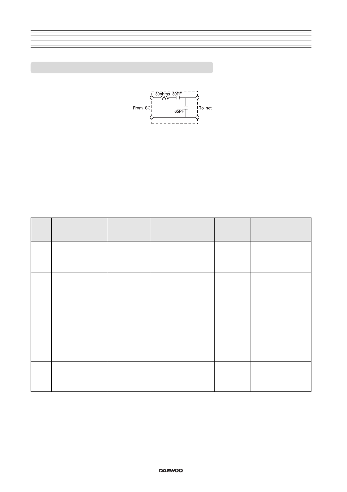
1. Dummy Antenna Circuit
2. Location of Adjustment Points
Refer to Adjustment Location Page
3. Control Setting
Power Switch .................. ON Balance/Fader Control ...................... Mech. Center
Band Switch .................... AM Treble/Bass Control ........................... Mech. Center
Other ............................... OFF
4. Adjustment Procedure
NOTE: When it is U.S.A band instead of 522, 603, 999, 1404kHz is 530, 600, 1000, 1400kHz
Page 14

ADJUSTMENTS
4-4. FM ADJUSTMENT METHOD
12
STEP
1 IF (Zero Volt)
RDS Receiving
estimation level
Figure 3
Figure 4
Figure 5
Figure 5
98.1MHz 60dBuV
No Modulation
98.1MHz 42dBuV
Mod.
1kHz 30% Mono
98.1MHz 60dBuV
Mod.
1kHz 30% Stereo Left
at Right ch.
98.1MHz 35dBuV
Mod.
1kHz 30% Stereo Left
at Right ch.
98.1MHz
98.1MHz
98.1MHz
98.1MHz
Adjust FM DET
for 0V + 0.03V
Fig.7
Adjust RV 108 Page7.
Tuner PC Board
for2.7V=20mV at
TP102(IC401 pin 66)
Adjust MPX SEP Fig.7
for maximum separation
Left and Right ch.
Adjust Stereo Blend
Fig.7 1dB separation
between Left and Right
ch.
Stereo Separation
SNC
4
5
6
DESCRIPTION
CONNECTION
ANTENNA SIGNAL
DIAL
CONTROL
ADJUSTMENT
1. Dummy Antenna Circuit
2. Location of Adjustment Points
Refer to Adjustment Location Page
3. Control Setting
Power Switch ................. ON Balance/Fader Control ..................... Mech. Center
Band Switch ................... FM Treble/Bass Control ......................... Mech. Center
Other ............................... OFF
4. Adjustment Procedure
Page 15

ADJUSTMENTS
4-5. TAPE ADJUSTMENT METHOD
13
NOTE : 1. Clean the playback head before adjustment
2. Prepare the test tape MTT-114 or equivalent
3. Balance, Fader, Bass & Treble ....Center position. Volume adjusted to 2Volts.
Note
: dBu uV
dBu uV
17 5.0 33 44.6
16 6.31 35 56.2
30 31.6 45 178
NOTE : Antenna signal is used.
1. For Signal Generator with readings in
EMF(Open type) add 12dB (6dB for the
“Dummy” and 6dB for EMF-reading).
2. For Signal Generator with reading in dBm add 6
dB for “Dummy”
STEP
1
Head azimuth
adjustment
Tape Speed
Figure 6
Figure 6
MTT-114N
or equivalent
MTT-114N
or equivalent
Speaker
Output
Speaker
Output
Head azimuth
adjustment screw
Turn the azimuth
screw to obtain
maximum level
Adjust for 30103020Hz
Tape Speed
adjustment
2
DESCRIPTION
TEST TAPE
CONNECTION
TEST
POINT
ADJUSTMENT
POINT
ADJUSTMENT
Page 16
14
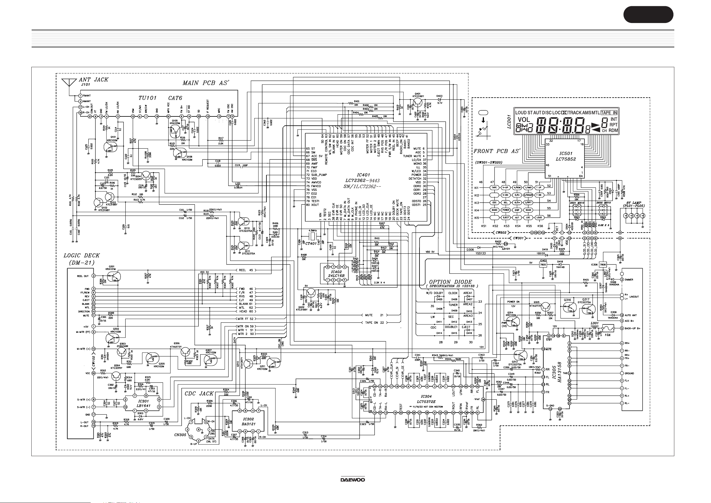
5. SCHEMATIC DIAGRAMS
5-1. BASIC Series AKF-0305 / AKF-0315
Size:A3
Page 17

15
5-2. RDS Series AKF-0305 / AKF-0315
SCHEMATIC DIAGRAM
Size:A3
Page 18

16
5-3. OIRT Series AKF-0305 / AKF-0315
SCHEMATIC DIAGRAM
Size:A3
Page 19

6-1. PCB MAIN : AKF-0305/0315
17
6. PARTS LOCATION ON P.C. BOARD
PARTS SIDE
Page 20

PARTS LOCATION ON P.C. BOARD
18
BOTTOM SIDE
Page 21

6-2. PCB FRONT
AKF-0305 BASIC
19
PARTS LOCATION ON P.C. BOARD
PARTS SIDE
BOTTOM SIDE
Page 22

20
PARTS LOCATION ON P.C. BOARD
AKF-0305 RDS
PARTS SIDE
BOTTOM SIDE
Page 23

21
PARTS LOCATION ON P.C. BOARD
AKF-0315 BASIC
PARTS SIDE
BOTTOM SIDE
Page 24

22
PARTS LOCATION ON P.C. BOARD
AKF-0315 RDS
PARTS SIDE
BOTTOM SIDE
Page 25

23
7. OVERALL EXPLODED VIEW & PARTS LIST
7-1. AKF-0305 Basic, RDS
Size:A3
Page 26

7-2. AKF-0315 Basic, RDS
24
OVERALL EXPLODED VIEW & PARTS LIST
Size:A3
Page 27

8-1. EXPLODED VIEW (ADM-21)
25
8. DECK MECHANISM EXPLODED VIEW & PARTS LIST
Page 28

DECK MECHANISM EXPLODED VIEW & PARTS LIST
26
8-2. PARTS LIST
No PART CODE
97YM002600
97YM002900
97Y0900800
97Y2100400
97Y2101000
97Y0900200
97Y8000300
97Y6400100
97YM003200
97Y3000400
97YM003100
97Y3000300
97Y2700400
97Y2700800
97Y2100500
97Y8100200
WP-7021563
97Y2700700
97Y2400200
97Y2700900
97YM003400
97YM003500
97Y2101400
97Y3000800
97Y3700100
97Y3000900
97Y2700600
97Y2900200
97Y4100100
97Y2700500
97Y3000600
97Y3100100
97Y4000100
97Y3000500
97Y0400100
97Y2101500
97Y2701200
PART NAME
CHASSIS MAIN SUB AS
LEVER GEAR LOAD AS
PLATE REVERSE
ARM EJ CAM
ARM TAPE SELECT
PLATE HEAD
HEAD AS
TERMINAL EARTH
ARM PINCH R AS
SPRING PINCH ARM (R)
ARM PINCH F AS
SPRING PINCH ARM (F)
GEAR REDUCTION
GEAR WORM WHEEL
ARM IN SW
MOTOR SUB
WIRE RIBBON
GEAR WORM
BRACKET MOTOR
CAM EJECT
BRACKET L AS
ARM TAPE CATCH A AS
ARM TAPE CATCH (B)
SPRING TAPE CATCH ARM
PULLEY IDLE
SPRING TU ARM
GEAR TU
REEL SPINDLE
FELT REEL
GEAR REEL
SPRING REEL
WASHER REEL
BUSHING REEL
SPRING REEL CAP
CAP REEL
ARM DETECT GEAR
GEAR DETECT
DESCRIPTION
ADM-22 FULL LOGIC DECK
ADM-22 FULL LOGIC DECK
SUS-304 1/2H T0.4
EGSAFC45R T0.8
EGSAFC45R T0.8
EGSAFC45R T0.8
HEAD+FPC
ET T0.2
ADM-22 FULL LOGIC DECK
SWP-B PI0.65 TORS
ADM-22 FULL LOGIC DECK
SWP-B PI0.65 TORS
POM DURACON M90-44 (N)
POM DURACON OL-10 (N)
EGSAFC45R T0.8
FF-050SH-11190
AWG28 2P
POM DURACON M90-44 (N)
EGSAFC45R T0.8
EGSAFC45R T0.8
ADM-22 FULL LOGIC DECK
ADM-22 FULL LOGIC DECK
EGSAFC45R T0.8
SWP-B PI0.65 EXTN
POM DURACON ES-5
SUS-403WPB PI0.2 EXTN
POM DURACON OL-10 (N)
POM DELRIN-500 (N)
FELT PI5.6XPI18XT0.8
POM DELRIN-500 (N)
SUS-304WPB PI0.7 CONE
PS PI4.0XPI18.0XT0.4
POM DURACON M90-44 (N)
SUS-304WPB PI0.3 COMP
POM DURACON M90-44 (N)
POM DURACON M90-44 (N)
POM DURACON M90-44 (BK)
1
2
3
4
5
6
7
8
9
10
11
12
13
14
15
16
17
18
19
20
21
22
23
24
25
26
27
28
29
30
31
32
33
34
35
36
37
ADM-22
Page 29

27
DECK MECHANISM EXPLODED VIEW & PARTS LIST
No PART CODE
97Y9300200
97Y3001100
97Y3001200
97Y0900400
97Y2700100
97Y3001300
97Y3001000
97Y0400200
97Y3300100
97Y3700700
97Y8100300
WP-7030803
97Y2900400
97Y5500200
1SPI31525-
5S40101A19
97Y6500700
97Y3900100
97Y0900100
97YC000500
97Y2300100
97Y0900700
97Y4200100
97Y2600100
97Y2101300
97Y2400300
97YC000600
97Y5700100
7003200211
7273200311
7273200411
7273170511
7273201011
7173260611
97Y3900200
97Y3900300
97Y3900600
97Y3900500
97Y3900700
PART NAME
LABEL REFLECTION
SPRING DETECT ARM
SPRING HEAD PLATE
PLATE REVERSE B
GEAR POWER
SPRING SELECT ARM
SPRING IN SW ARM
COVER BRUSH
BRUSH CONTROL
PULLEY MOTOR
MOTOR MAIN
WIRE RIBBON
FLYWHEEL AS
BELT MAIN
IC PHOTO REFLECTOR
SW PUSH
PCB REFLECTOR A
POLYSLIDER FLYWHEEL
PLATE BOTTOM
PCB CONNECTION AS
HOLDER CASSETTE
PLATE SPG CASS HOLD
CUSHION HOLDER
HOOK TAPE
HANGER CASSETTE
BRACKET PCB
PCB EQ AS
STOPPER REV PLT B
SCREW MACHINE
SCREW TAPTITE
SCREW TAPTITE
SCREW TAPTITE
SCREW TAPTITE
SCREW TAPTITE
POLYSLIDER WASHER
POLYSLIDER WASHER
POLYSLIDER WASHER
POLYSLIDER WASHER
POLYSLIDER WASHER
DESCRIPTION
ALS T0.05 PI15.8
SWP-B PI0.4
AWP-B PI0.4 EXTN
EGSAFC45R T0.8
SMF5030
SUS-304WPB PI0.25 EXTN
SUS-304WPB PI0.25 EXTN
POM DURACON M90-44 (BK)
GNP T0.1
MBSBM
MC15U3LDCN
AWG28 3P
ZDC2/C2700/SUS-420J2
EPDM PI120.3XT1
SPI-315-25
SW-110 1C-1P NORMAL OPEN
XPC 78X57XT0.8
PS PI8.0XT0.3
EGSAFC45R T0.6
ADM-22 FULL LOGIC DECK
EGSAFC45R T0.8
SUS-304WPB T0.2
EVA 6.5X6.5XT1.0
POM DURACON M90-44 (N)
EGSAFC45R T0.8
SECC-E T0.8
ADM-22 FULL LOGIC DECK
SUS-304 T0.2
BIN M2X2.5 MFZN
TT3 BIN 2X3 MFZN
TT3 BIN 2X3.5 MFZN
TT3 BIN 1.7X5 MFZN
TT3 BIN 2X10 MFZN
TT2 BIN 2.6X6 MFZN
PS PI1.2XPI3.2XT0.25
PS PI1.5XPI3.2XT0.25
PS PI1.5XPI3.2XT0.4
PS PI2XPI4XT0.4
PS PI1.9XPI3.2XT0.25
38
39
40
41
42
43
44
45
46
47
48
49
50
51
52
53
54
55
56
57
58
59
60
61
62
63
64
65
S1
S2
S3
S4
S5
S6
W1
W2
W3
W4
W5
ADM-22
Page 30

9-1. MAIN SECTION
28
DESCRIPTION
1SAA6579T-
IC101
IC DRIVER LB16411LB1641---
IC301
IC ISOLATION BA-3121 (When it is CD Changer)1BA3121---
IC302
1LC75372E-
IC304
IC AUDIO POWER HA13158A1HA13158A-
IC305
IC REGULATOR KIA 7808P TO-220AB1K1A7808P-
IC306
IC CHIP CUSTOM LC72366-9433, W/RDS Version
LC72362-9443, W/O RDS Version
1LC72366-1LC72362--
IC401
IC CHIP EEPROM 24LC16B-1/SN124LC16BSQ
IC402
IC REGULATOR KIA78S05P AUTO1Z1A78S05P
IC403
JACK ANT ANT. J-020-03 97T6366900
J101
LED LT6311-S4 RED WITH HOLDERDLT6311S4-
LD101
COIL CHOKE 37 x 1 x 5.2 300UH P EI-19MM5LC301PA18
L301
R SEMI FIXED H500K-5 x 5-6N-PC-BSRV1417504-
RV108
TUNER MODULE CET-6048 FM/MW/LW
*OIRT BAND
TUNER FM 1-CHIP AS CAT-7-NC
97T7609100
PNFCMBJV00
TU001
WIRE LEAD AWG26 7/0. 16 RD 10-100-10W144RD1017
W01, W13
CRYSTAL QUARTZ HC-49/S 4.332MHZ 25PPM5XJZ4R332D
CT102
CRYSTAL QUARTZ HC-49/S 4.5MHZ 30PPM5XJZ4R500E
CT401
DIODE ZENER MTZ-10V 26MM TAPPING DKTZ10B---
D102
D102
DIODE ZENER MTZ-9.1V AUTO 26MM
*OIRT BAND
DKTZ9R1B--
DKTZ5R1B--
D104, D403
DIODE KN4004A AUTO 26MM
D301, D307, D308
D309, D310
DIODE ZENER MTZ-9.1V AUTO 26MM
DIODE ZENER MTZ-6.8V AUTO 26MM
DKTZ9R1B--
D302, D305
DKTZ6R8B--
D303
DIODE 1SS133 AUTO 26MM
DKSS133---
D304, D306, D313
D401, D404, D405
D409, D410, D411
D413, D416, D419
D420, D421, D422
D423, D424, D426
D427
DIODE ZENER MTZ-5.6V AUTO 26MM
DIODE ZENER MTZ-6.2V AUTO 26MM
DKTZ5R6B--
D402
DKTZ6R2B--
D417
DIODE KN4148 AUTO 26MMDKN4148---
D418, D429
COIL INDUCTOR 0.56UH K 02 TA 26MM
*Option
5LL568K02K
L101
TR KRC102M (KEC)
TZRC102M--
Q101, Q106, Q109
Q302, Q305, Q307
Q311, Q314
TR KTC-3199Y TAPPING
TZTC3199Y-
Q102, Q103, Q304
Q401, Q402
Ref
PART NO.
IC AUDIO SAA6579T (RDS Demodulator)
IC CHIP EVR LC75372E MFP36S
DIODE ZENER MTZ-5.1V AUTO 26MM
DKN4004A--
9. PARTS LIST
R
R
R
R
R
R
R
CAUTION
is a recommendable part for essential stock.
R
Page 31

PARTS LIST
29
DESCRIPTION
TR KTC3205Y (2236Y)
TR KTA-105M
TR DTC323TSA SPT
TR KRA 101M AUTO (2201)
TR 2SB1240R
TR KTA1273Y (966Y)
TR KTA1267Y TAPPING
PART NO.
TZTC3205Y-
Ref
DESCRIPTIONPART NO.
Ref
Q104
TZRA105M--
Q105, Q107
TZDTC323TS
Q110, Q111, Q313
Q316, A317
TZRA101M--
Q301
TZ2SB1240R
Q303
TZTA1273Y-
TZTA1267Y-
Q306, Q315
Q310
IC DRIVER LC75854E QIP64E, with RDS Version1LC75854E-
IC501
LC75852, W/O RDS Version1LC75852--
LCD TTD-1464UPTDPN with RDS Version97T0L1160P
LCD
TTD-1869UPTDPN, W/O RDS Version97T0L1320P
PL01 ~ PL05
LAMP PILOT 8V 60MA D3. 2 0. 08
SW TACT 1C-1P SKQC10918B 260G
SW TACT 1C-1P KPT-1107BC 200G
97T82L0D86
5S50101Z02
SW01
DIODE CHIP 1MN10
5S51120CK1
D1MN10---B
SW02
D501 ~ D504
9-2. FRONT SECTION
R
R
R
R
R
R
Page 32

30
10. FUNCTION OF MICOM IC
10-1. PIN CONFIGURATION (TOP VIEW) : RDS MODEL ONLY
Page 33

31
FUNCTION OF MICOM IC
10-2. PIN DESCRIPTION
PIN
1
80
78
77
71
76
73
31
75
74
72
70
69
68
67
79
51
50
PIN NAME
XIN 4.5MHz CRYSTAL
PHASE COMPARISON OUTPUT PORT
If the frequency of the partial oscillation is higher than the basic
frequency, these output high, lower than the basic frequency, output
low. Otherwise, these are high-z that those frequencies correspond.
AM 2 nd CHARGE PUMP OUTPUT PORT.
(AM FREQUENCY : 90kHz)
CAN BE SUPPLIED UP TO 6.5V
FM VCO INPUT
(the signal of the partial oscillation)
* INPUT RANGE : 0.07~1.5 Vrms
* INPUT RANGE : 0.07~1.5 Vrms
Outputs the pll lock up signal to lock up the pll frequency in
high speed.
FM IF COUNT INPUT
*
INPUT RANGE : 10.7MHz+30kHz, Vpp=0.07~1.5Vrms
AM IF COUNT INPUT
* INPUT RANGE : 450kHz + 1kHz (AM)
: 450kHz + 0.37kHz (LW)
* Vpp = 0.07 ~1.5Vrms
To check if the memory state is normal on the back-up mode.
The application circuit is illustrated on the note of back pages.
To check if it is back-up mode(LOW) or normal operation state(HIGH),
but it display clock depending on the clock option.
Connect to ground.
Dm-21 loading motor control port.
MTR1 MTR2
LOADING : HIGH LOW
EJECT : LOW HIGH
STOP : LOW LOW
AM VCO INPUT
(the signal of the partial oscillation)
XOUT
E01
E02
E03
VSS
VDD
VDD
FMIN
AMIN
SUBPD
HCTR
LCTR
SNS_
HOLD_
TEST1
TEST2
PL1
PL2
DESCRIPTION I/O
I
O
O
O
O
--
--
--
I
I
O
I
I
I
I
--
--
O
O
Page 34

32
FUNCTION OF MICOM IC
PIN
59
52
53
54
55
11
12
13
14
21
40
38
39
27
28
29
30
23
24
25
26
7
8
9
63
35
PIN NAME
PJ1
PL0
DM-21 MAIN MOTOR CONTROL PORT.
INPUT DATUM FROM THE RDS DEMODULATOR IC THE
TIMING CHART OF DATA IS ILLUSTRATED ON BACK
PAGES.
KEY & LCD DRIVER IC INTERFACE PORTS
EVR IC INTERFACE PORTS.
OPTION DIODE MATRIX INPUT.
OPTION DIODE MATRIX OUTPUT.
RDS DATA MEMORY EEPROM CONTROL PORT.
MULTI-PATH INPUT PORT.
* INPUT RANGE : 0.6~0.9V
LCD BACK-LIGHTING COLOR CONTROL PORT
RESET : COLOR
---
> LOW
TWO KEY IN : COLOR CHANGE
DECK EQ IC MUTE ADJUST PORT.
PK3
PK2
INT1
PE3/SI2
PE2/SO2
PE1/SCK2
PE0
PC1
PO0
PO2
PO1
PA3
PA2
PA1
PA0
PB3
PB2
PB1
PB0
PF3
PF2
PF1
PF3
PP1
DESCRIPTION I/O
O
O
I
I
I
I
O
O
O
O
O
O
O
I
I
I
I
O
O
O
O
I
O
O
I
O
MTR_ON MTR_FF
PLAY : HIGH LOW
FF/REW : HIGH HIGH
STOP : LOW LOW
Page 35

33
FUNCTION OF MICOM IC
KEY MATRIX TABLE
RETURN
SOURCE
KS 6 (49)
M1 (AMS)
T. U P
KI 1 (50) KI 2 (51) KI 3 (52) KI 4 (53) KI 5 (54)
T. DOWN
M2 (DOLBY)
M5
(DISC DOWN)
VOL DOWN
---
---
SEEK UP
M3 (RPT)
M6
(DISC UP)
SELECTOR
CDC/PAUSE
AUX
SEEK DOWN
LOC
TA/TA_STBY
PTY(DISP)
POWER
ON/OFF
RADIO/BAND
(LANG)
MONO
LOUD/LOC
AF/REG
ATP
TAPE EJECT
MUTE
---
M4 (SHUF)
VOL UP
TAPE/PGM
---
KS 5 (48)
KS 4 (47)
KS 3 (46)
KS 2 (45)
KS 1 (44)
KEY MATRIX TABLE
DIODE MATRIX DESCRIPTIONS
SOURCE
RETURN
ODR 3
(PA3, 27PIN)
DOUBLE 2
(D405)
---
ODST 3
(PB3, 23PIN)
ODST 2
(PB2, 24PIN)
ODST 1
(PB1, 25PIN)
ODST 0
(PB0, 26PIN)
---
LOUD/LOC
(D408)
TUNER 1,2
(D409)
AREA 2
(D410)
---
LW ENABLE
(D411)
---
AREA 3
(D413)
---
CDC/AUX IN
(D414)
DOUBLE 1
(D415)
---
CLOCK
(D406)
AREA 1
(D407)
ODR 2
(PA2, 28PIN)
ODR 1
(PA1, 29PIN)
ODR 0
(PA0, 30PIN)
-LW select (D411) 0 : LW BAND DISABLE
1 : LW BAND ENABLE
-CLOCK USE select (D406) 0 : CLOCK ENABLE
1 : CLOCK DISABLE
-LOUD/LOC USE select(D408) 0 : LOUD/LOCAL KEY DOUBLE FUNCTION
1 : LOUD KEY ONLY
-TUNER 1,2 select (D409) 0 : CAT6 or CAT7 TUNER See page 13
1 : CET6038AFL TUNER
-DOUBLE 1,2 (D415. D405)select
DOUBLE 1
(D415)
DOUBLE 2
(D405)
MEMORY 1 MEMORY 2
0
0 1 AMS
0 AMS DOLBY
---
Page 36

34
FUNCTION OF MICOM IC
10-3. PIN CONFIGURATION (TOP VIEW) : NON RDS MODEL ONLY
Page 37

35
FUNCTION OF MICOM IC
10-4. PIN DESCRIPTION
PIN
1
80
78
71
76
73
31
75
74
72
70
69
68
67
79
51
50
PIN NAME
XIN 4.5MHz CRYSTAL
PHASE COMPARISON OUTPUT PORT
If the frequency of the partial oscillation is higher than the basic
frequency, these output high, lower than the basic frequency, output
low. Otherwise, these are high-z that those frequencies correspond.
AM 2 nd CHARGE PUMP OUTPUT PORT.
(AM FREQUENCY : 90kHz)
CAN BE SUPPLIED UP TO 6.5V
FM VCO INPUT
(the signal of the partial oscillation)
* INPUT RANGE : 0.07~1.5 Vrms
* INPUT RANGE : 0.07~1.5 Vrms
Outputs the pll lock up signal to lock up the pll frequency in
high speed.
FM IF COUNT INPUT
*
INPUT RANGE : 10.7MHz+ 30kHz, Vpp=0.07~1.5Vrms
AM IF COUNT INPUT
* INPUT RANGE : 450kHz + 1kHz (AM)
: 450kHz + 0.37kHz (LW)
* Vpp = 0.07~1.5Vrms
To check if the memory state is normal on the back-up mode.
The application circuit is illustrated on the note of back pages.
To check if it is back-up mode(LOW) or normal operation state(HIGH),
but it display clock depending on the clock option.
Connect to ground.
Dm-21 loading motor control port.
MTR1 MTR2
LOADING : HIGH LOW
EJECT : LOW HIGH
STOP : LOW LOW
AM VCO INPUT
(the signal of the partial oscillation)
XOUT
E01
E02
E03
VSS
VDD
VDD
FMIN
AMIN
SUBPD
HCTR
LCTR
SNS_
HOLD_
TEST1
TEST2
PL1
PL2
DESCRIPTION I/O
I
O
O
O
O
--
--
--
I
I
O
I
I
I
I
--
--
O
O
Page 38

36
FUNCTION OF MICOM IC
PIN
59
52
11
12
13
14
21
40
38
39
27
28
29
30
23
24
25
26
7
8
9
63
35
PIN NAME
PJ1
PL0
DM-21 MAIN MOTOR CONTROL PORT.
KEY & LCD DRIVER IC INTERFACE PORTS
EVR IC INTERFACE PORTS.
OPTION DIODE MATRIX INPUT.
OPTION DIODE MATRIX OUTPUT.
SECURITY MEMORY EEPROM CONTROL PORT.
REMOCON INPUT PORT.
LCD BACK-LIGHTING COLOR CONTROL PORT
RESET : COLOR
---
> LOW
TWO KEY IN : COLOR CHANGE
DECK EQ IC MUTE ADJUST PORT.
PE3/SI2
PE2/SO2
PE1/SCK2
PE0
PC1
PO0
PO2
PO1
PA3
PA2
PA1
PA0
PB3
PB2
PB1
PB0
PF3
PF2
PF1
PF3/ADI3
PP1
DESCRIPTION I/O
O
O
I
O
O
O
O
O
O
O
I
I
I
I
O
O
O
O
I
O
O
I
O
MTR_ON MTR_FF
PLAY : HIGH LOW
FF/REW : HIGH HIGH
STOP : LOW LOW
Page 39

37
FUNCTION OF MICOM IC
KEY MATRIX TABLE
RETURN
SOURCE
KS 6 (51)
M1 (AMS)
T. U P
KI 1 (52) KI 2 (53) KI 3 (54) KI 4 (55) KI 5 (56)
T. DOWN
M2 (DOLBY)
M5
(DISC DOWN)
VOL DOWN
---
---
SEEK UP
M3 (RPT)
M6
(DISC UP)
SELECTOR
CDC/PAUSE
AUX
SEEK DOWN
---
SCAN
DISP
POWER
ON/OFF
RADIO/BAND
MONO
LOUD
LOC
ATP
TAPE EJECT
MUTE
---
M4 (SHUF)
VOL UP
TAPE/PGM
---
KS 5 (50)
KS 4 (49)
KS 3 (48)
KS 2 (47)
KS 1 (46)
OPTION DIODE TABLE
DIODE MATRIX DESCRIPTIONS
SOURCE
RETURN
ODR 3
(PA3, 27PIN)
DOUBLE 2
(D405)
---
ODST 3
(PB3, 23PIN)
ODST 2
(PB2, 24PIN)
ODST 1
(PB1, 25PIN)
ODST 0
(PB0, 26PIN)
---
---
TUNER 1,2
(D409)
AREA 2
(D410)
---
LW ENABLE
(D411)
---
AREA 3
(D413)
---
CDC/AUX IN
(D414)
DOUBLE 1
(D415)
---
CLOCK
(D406)
AREA 1
(D407)
ODR 2
(PA2, 28PIN)
ODR 1
(PA1, 29PIN)
ODR 0
(PA0, 30PIN)
-LW select (D411) 0 : LW BAND DISABLE
1 : LW BAND ENABLE
-CLOCK USE select (D406) 0 : CLOCK ENABLE
1 : CLOCK DISABLE
-LOUD/LOC USE select(D408) 0 : LOUD/LOCAL KEY DOUBLE FUNCTION
1 : LOUD KEY ONLY
-TUNER 1,2 select (D409) 0 : CAT6 or CAT7 TUNER See page 13
1 : CET6038AFL TUNER
-DOUBLE 1,2 (D415. D405)select
DOUBLE 1
(D415)
DOUBLE 2
(D405)
MEMORY 1 MEMORY 2
0
0 1 AMS
0 AMS DOLBY
---
Page 40

38
FUNCTION OF MICOM IC
DIODE
AREA
AREA1
(D407)
AREA2
(D410)
AREA3
(D416)
EUROPE
CHINA
USA1
USA2
Australia
Middle East
OIRT
1
0
0
1
0
0
1
0
0
0
1
1
1
1
0
0
0
1
AREA 1, 2, 3
Page 41

39
11. IC BLOCK DIAGRAM
11-1. LC75854/LC75852 (IC LCD DRIVER) : IC501
Page 42

40
IC BLOCK DIAGRAM
11-2. SAA6579T (IC AUDIO) : IC101
Page 43

41
IC BLOCK DIAGRAM
11-3. HA13158A (IC AUDIO POWER) : IC305
Page 44

IC BLOCK DIAGRAM
42
11-4. LC75371M (IC EVR)
Page 45

IC BLOCK DIAGRAM
43
11-5. 24LC16B (IC EEPROM) : IC402
Page 46

IC BLOCK DIAGRAM
44
11-6. BA3121 (IC ISOLATOR) : IC302
Page 47

IC BLOCK DIAGRAM
45
11-7. LB1641 (DRIVER) : IC301
Page 48

46
12. LIQUID CRYSTAL DISPLAY
12-1. RDS ONLY
IC NO
LCD NO.
COM1
COM2
COM3
COM4
6
123456789101112131415
DOLBY
9B 9H 9A RPT 8B 8H 8A RDM 7B 7H 7A --- 6B 6H
MTL 9I 9G 9O 9F 8I 8G 8O 8F 7I 7G 7O 7F 6I 6G
AMS 9C 9K 9L 9N 8C 8K 8L 8N 7C 7K 7L 7N 6C 6K
TAPE IN
INTRO
9D 9M 9E
TRACK
8D 8M 8E DOT 7D 7M 7E
DISC
6D
4 5 7 39 38 37 36 35 34 33 30 34 32 29
IC NO
LCD NO.
COM1
COM2
COM3
COM4
13
31 32 33 34 35 36 37 38 39 40
2H 2A 1D LOC
LOUD COM1
--- --- ---
2G 2O 2F 1C 1E MO ---
COM2
--- ---
2K 2L 2N 1G 1F CH --- ---
COM3
---
2D 2M 2E 1B 1A AUT --- --- ---
COM4
12 11 10 9 8 40 41 42 43
IC NO
LCD NO.
COM1
COM2
COM3
COM4
28
16 17 18 19 20 21 22 23 24 25 26 27 28 29 30
6A PTY 5B 5H 5A --- 4B 4H 4A --- 3B 3H 3A TA 2B
6O 6F 5I 5G 5O 5F 4I 4G 4O 4F 3I 3G 3O 3F 2I
6L 6N 5C 5K 5L 5N 4C 4K 4L 4N 3C 3K 3L 3N 2C
6M 6E 5D 5M 5E AF 4D 4M 4E TP 3D 3M 3E ---
27 26 25 24 23 22 21 20 19 18 17 16 15 14
Page 49

47
LIQUID CRYSTAL DISPLAY
12-2. BASIC ONLY
IC NO
LCD NO.
COM1
COM2
1
123456789101112131415
LOUD
AUT
1A,1G
1H 1B
2B,2C
2E,2F
2D LOC 3B
3A,3D
3G
4A 4G 4C
4B
5A
ST
DISC
TRACK
1E,1F
1D 1C 2A VOL 3C 3E 4F 4E 4D 4H 5F
23456789101314151617
IC NO
LCD NO.
COM1
COM2
18
16 17 18 19 20 21 22 23 24 25 26 27 28 29 30
5G 5C 5B 6A 6G 6C 6B 7A7F7G 7C 7B 8A 8G
8C
8B
5E 5D 5H 6F 6E 6D 6H 7E 7D P 8F 8E 8D
19 20 21 22 23 24 25 26 27 28 29 30 31 32
IC NO
LCD NO.
COM1
COM2
33
31 32 33 34 35 36 37 38 39 40
9A 9G 9C 9B CH INT
TAPE IN
AMS
DOLBY
COM1
---
9F 9E 9D CH RPT MTL ---
COM2
34 35 36 37 38 39 40 44 45
Page 50

13. OUTPUT CONNECTOR DESCRIPTIONS
48
OUTPUT CONNECTORS
13PIN CONNECTOR
8PIN CONNECTOR 26PIN ISO CONNECTOR
18PIN CONNECTOR
1
REAR LEFT SP(-)
REAR RIGHT SP(+)
NEGATIVE GROUND
RIGHT (ILLUMINATION)
BATTERY B+(BACK-UP)
FRONT RIGHT SP(-)
FRONT LEFT SP(-)
REAR RIGHT SP(-)
AUTO ANT
ACC B(+)POWER
FRONT RIGHT SP(+)
FRONT LEFT SP(+)
REAR LEFT SP(+)
8
9
10
11
12
13
2
3
4
5
6
7
1
CDC-ON
BACK-UP B+
NO CONNECTION
DATA
GROUND
R-CH
L-CH
SIGNAL GROUND
2
3
4
5
6
7
8
1
FRONT R-CH SP(+)
REAR R-CH SP(-)
ILLUMINATION (-)
AUTO ANT. B+
NO CONNECTION
GROUND
NO CONNECTION
NO CONNECTION
REAR L-CH SP(-)
FRONT L-CH SP(-)
REAR R-CH SP(+)
ILLUMINATION(+)
ACC. B(+)
BACK UP B+
NO CONNECTION
REAR L-CH SP(+)
FRONT L-CH SP(+)
FRONT R-CH SP(-)
10
11
12
13
14
15
16
17
18
2
3
4
5
6
7
8
9
4. yellow...back-up
dc+12v
5. blue...remote
dc+12v(power ant)
6. Dimmer(option)
7. red...power supply
8. black...ground
1. vilot...rear right(+)
2.
vilot/black...rear right(-)
3. gray.../front right(+)
4.
gray/black...front right(-)
5. white...front left(+)
6.
white/black...front left(-)
7. green...rear left(+)
8.
green/black...rear left(-)
C OTHERS
5. black...ground
6. orange...12v preamp(+)
8. red...preamp R-ch
10. white...preamp L-ch
A
BC
Page 51

DAEWOO ELECTRONICS CO., LTD
686, AHYEON-DONG MAPO-GU
SEOUL, KOREA
C.P.O. BOX 8003 SEOUL, KOREA
TELEX : DWELEC K28177-8
CABLE : “DAEWOOELEC”
E-mail : G7F00E@web.dwe.co.kr
TEL : 82-2-360-7799
FAX : 82-2-360-7877
edited by Mc. Cem
 Loading...