

Daesung Maref DVT 2600 Service Manual
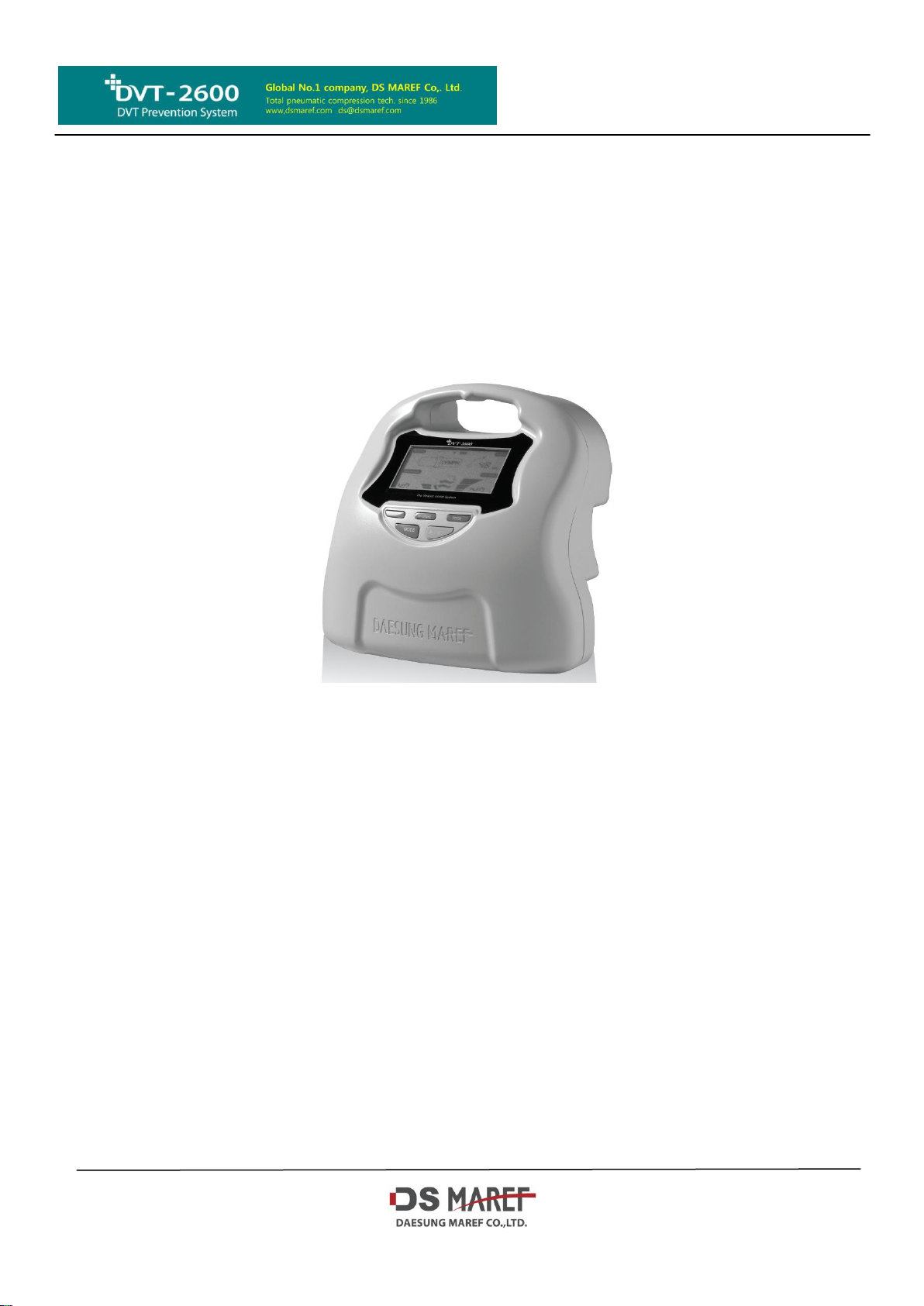
Service & Maintenance manual
Indications for safety use
Read this manual carefully.
This manual is for user’s safety and preventing any property-loss.
Before using our device, please inevitably
Daesung Maref Co., Ltd.
296-24, Gongdan-ro, Gunpo-shi, Gyeonggi-do, Korea
T +82 31 459 7211 F +82 31 459 7215 www.dsmaref.com e-mail:ds@dsmaref.com
INTRO
This service & maintenance is published as a technical guide for system malfunctions. Unauthorized service
will void the warranty.
This services manual is not for a user and must be performed by technically qualified service personnel.
Daesung Maref warrants that defective materials can be replaced with free charge under warranty period.
The entire obligation is under these warranted regulations.
I. Display and indications of each controller
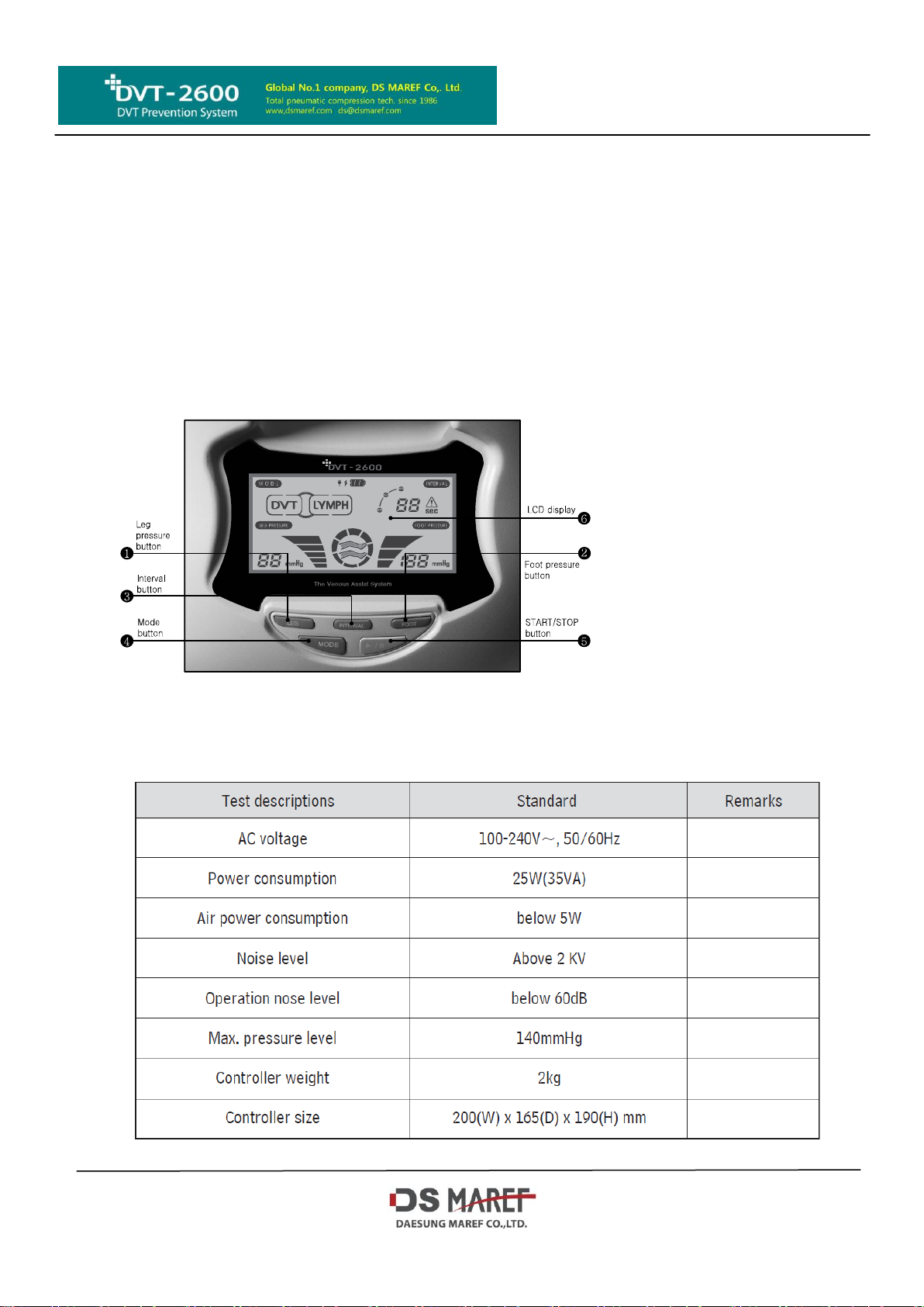
(1) Name of each part
Specifications and Dimensions
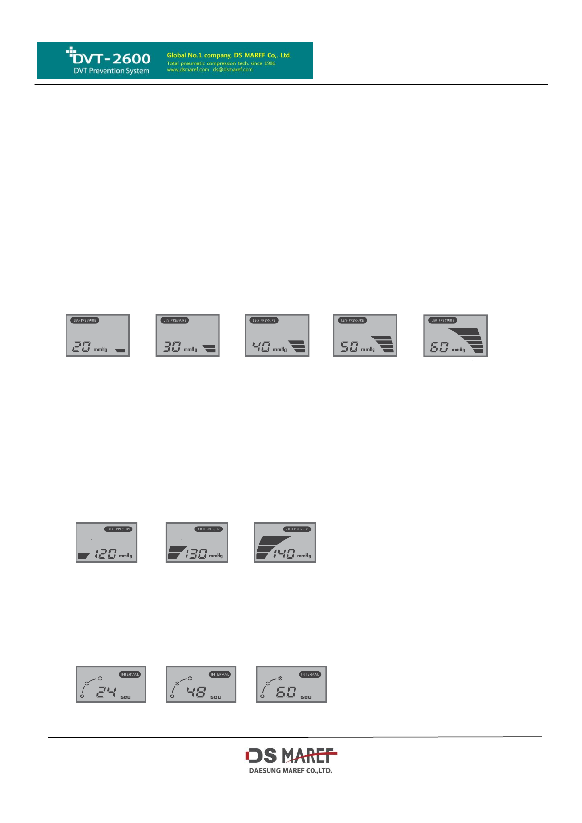
■ Leg pressure control button
This is a button to set the pressure to be operated. When the user presses
START/STOP button, the value which the user set will be selected up to the type
of cuff. (LEG/CALF/BOOT CUFF: 40mmHg). It is not able to change the setting
during operating.
Basic pressure is set as 40 mmHg, and the setting pressure will be changed 10
mmHg per each time pressing the button (ex. 40→50→60→20→30→40mmHg).
LCD screen will be off when the user does not apply the cuff because the
controller selects the cuff automatically when the user presses START/STOP
button.The latest saving value will be just saved when the power on again.
The controller has the automatic gradient pressure application that the gradient
pressure is applied into each chamber of a cuff sequentially in order of 100%,
80% and 60% to the upper direction, in the case of cuffs with 3 chambers like
leg/calf/boot cuff.
■ Foot pressure control button
This is a button to set the pressure to be operated. When the user presses STA
START/STOP button, the value which the user set will be selected up to the type
of cuff. (FOOT CUFF: 120mmHg). It is not able to change the setting during
operating.
Basic pressure is set as 120mmHg, and the setting pressure will be changed 10
mmHg per each time pressing the button (ex. 120→130→140→120mmHg). LCD
screen will be off when the user does not apply the cuff because the controller
selects the cuff automatically when the user presses START/STOP button. The
latest saving value will be just saved when the power on again.
■ INTERVAL Button
This is a button to set the interval time. The time value which the user set will be
saved when the power on. Basic time is set as 48sec, and it will be changed 48
→60→24→48sec per each time pressing the button. After completion of press
urization to each chamber, the controller has the interval time for vein refilling,
and the controller restart to pressurize the chambers again. This operation will
be repeated during the operating time. The latest saving value will be just saved
when the power on again. It is not able to change the setting during operating.
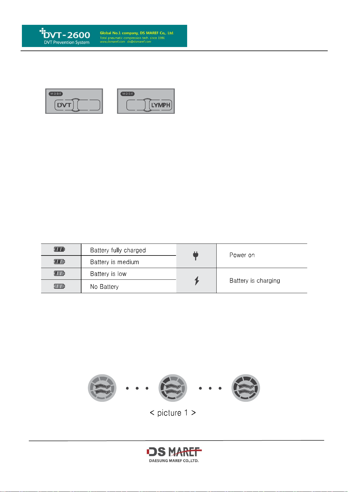
■ MODE button
This is a button to set the mode to be operated. Basic setting value will be set
as DVT MODE when the initial power on. When the user changes the mode, the
l atest mode will be saved. The latest mode will be set when the power on again.
■ START/STOP button
This is a button to start or stop the operation. It goes back to STOP mode when
the user presses START/STOP button during the error mark on the screen
■ LCD display screen
● 1) Battery status indicator
DVT-2600 is equipped with the basic battery pack. There are four battery
status indicators LED’s used to represent the charge level of the battery.
(Battery full, Battery medium, Battery low, No battery)
● 2) AC Power indicator
AC power indicator (LED) represents one of power input or the fail of
power input.
● 3) Battery charging indicator
It is divided into battery charging and battery not charging. The charge of
battery pack can not be available in the condition that power switch is not
ON. Charging battery will be only available when the battery is not fully charged.
※ Even though the battery is not fully charged, it is not available to charge the
battery during the state of no power on. The battery is a consumable supply.
The warranty period for the battery will be 6 months after the date of purchasing.
Do not take battery out arbitrary from the device.
● 4) Operation indicator
It shows the normal operation condition and the type of applied cuffs.
Initial self-test to perceive the type of applied cuff
When the user turns on the device, the controller starts to check the type of
applied cuff. During the controller check the type of applied cuff, two all legs
indicators and circle indicators are operating together.
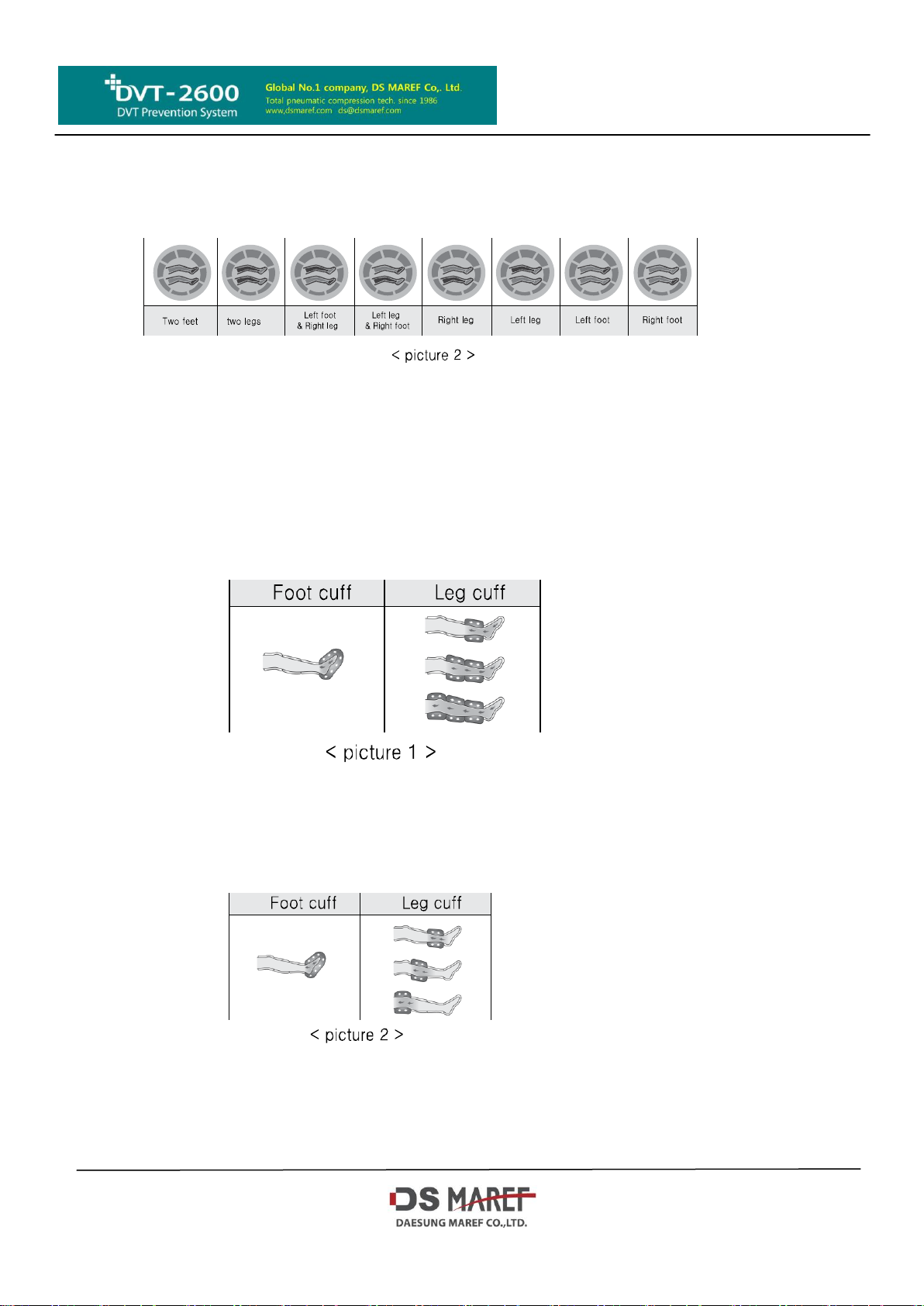
The operation indicator displays the only part of a cuff type is applied to the
controller as the below picture 2 after completing the self-test of perception of the
cuff. If there is no any cuff applied to the controller, it displays error code.
Operating Mode
The operating mode is divided into DVT and LYMPH mode.
During normal operation, the operation indicator activates repeatedly.
● 1) DVT Operating Mode
To select DVT Mode, the controller pressurizes the cuffs. (Refer to the
picture 1) If the user put different cuffs, it starts to give a pressure to foot
cuff first, then starts to give a pressure to leg cuff. Interval time will start
after finishing both legs’ pressure.
● 2) Lymph Operating Mode
To select Lymph Mode, controller starts to pressurize the cuffs following
picture 2. If the user put different cuffs, it starts to give a pressure to foot
cuff first, then starts to give a pressure to leg cuff. Interval time will start
after finishing both legs’ pressure
■ Interval Mode
All cuffs’ pressure finished, it will not give a pressure during interval time.
During this time, interval time setting on LCD will decrease gradually.
It restarts to give a pressure after finishing interval time.
 Loading...