


TDX3600
TDX7000
TDX9000
AMPLIFIERS
MANUALE UTENTE
USER MANUAL
IT - EN

Music & Lights S.r.l. si riserva ogni diritto di elaborazione in qualsiasi forma delle presenti istruzioni per l’uso.
Al ne di migliorare la qualità dei prodotti, la Music&Lights S.r.l. si riserva la facoltà di modicare, in
qualunque momento e senza preavviso, le speciche menzionate nel presente manuale di istruzioni.
Tutte le revisioni e gli aggiornamenti sono disponibili nella sezione 'Manuali' sul sito www.musiclights.it
In order to improve the quality of products, Music&Lights S.r.l. reserves the right to modify the
La riproduzione - anche parziale - per propri scopi commerciali è vietata.
All rights reserved by Music & Lights S.r.l. No part of this instruction manual may be
reproduced in any form or by any means for any commercial use.
characteristics stated in this instruction manual at any time and without prior notice.
All revisions and updates are available in the ‘manuals’ section on site www.musiclights.it
REV.001-07/13

TDX3600/7000/9000
ENIT
3
INDICE
Sicurezza
Avvertenze generali
Attenzioni e precauzioni per l’installazione
Informazioni generali
Descrizione e specifiche tecniche
Introduzione
Elementi di comando e di collegamento
Funzioni e impostazioni
Funzioni di protezione
Sistema di raredd. e protezione termica
Protezione in corrente sui transistors nali
Protezione sui diusori
Protezione VHF
Clip/Limit
Modalità di connessione
Modalità stereo
Modalità parallel
Modalità bridge
Cavi di collegamento
Collegamenti di ingresso
Collegamenti di uscita
4
5
6
7
10
15
15
16
16
16
16
18
20
22
24
24
CONTENTS
Safety
General instructions
Warnings and installation precautions
General information
Description and technical specifications
Introduction
Operating elements and connections
Functions and settings
Reliability protection function
Cooling system and thermal protection
Current protection on the output transistors
Loudspeakers protection
VHF protection
Clip/Limit
Connection mode
Stereo mode
Parallel mode
Bridge mode
Connection cable
Input connection
Output connection
4
5
6
7
10
15
15
16
16
16
16
18
20
22
24
24
Connettori
Connettori di potenza speakon
Connettori di segnale XLR
Manutenzione
Manutenzione ordinaria
Manutenzione e risoluzione dei problemi
Specifiche tecniche
Brevi cenni di acustica
Certificato di garanzia
Contenuto dell'imballo:
• TDX3600/7000/9000
• Cavo di alimentazione
• Manuale utente
25
25
26
26
27
28
Connector
Speakon power connector
XLR signal connector
Maintenance
Ordinary maintenance
Maintenance and troubleshooting
Technical specification
Brief notes on acoustic
Warranty
Packing content:
• TDX3600/7000/9000
• Power cord
• User manual
25
25
26
26
27
28

4
TDX3600/7000/9000
ENIT
ATTENZIONE!
Prima di effettuare qualsiasi operazione con
l’unità, leggere con attenzione questo manuale
e conservarlo accuratamente per riferimenti
futuri. Contiene informazioni importanti riguardo
l’installazione, l’uso e la manutenzione dell’unità.
SICUREZZA
Avvertenze generali
• I prodotti a cui questo manuale si riferisce sono
conformi alle Direttive della Comunità Europea e pertanto recano la sigla .
• Il dispositivo funziona con pericolosa tensione
di rete 230V~. Non intervenire mai al suo interno al di fuori delle operazioni descritte nel
presente manuale; esiste il pericolo di una scarica elettrica.
• È obbligatorio eettuare il collegamento ad
un impianto di alimentazione dotato di un’efciente messa a terra (apparecchio di Classe I
secondo norma EN 60598-1). Si raccomanda,
inoltre, di proteggere le linee di alimentazione
delle unità dai contatti indiretti e/o cortocircuiti verso massa tramite l’uso di interruttori dierenziali opportunamente dimensionati.
• Le operazioni di collegamento alla rete di
distribuzione dell’energia elettrica devono
essere eettuate da un installatore elettrico
qualicato. Vericare che frequenza e tensione
della rete corrispondono alla frequenza ed alla
tensione per cui l’unità è predisposta, indicate
sulla targhetta dei dati elettrici.
• L’unità non per uso domestico, solo per uso
professionale.
• Evitare che nell’unità penetrino liquidi inammabili, acqua o oggetti metallici.
• Non smontare e non apportare modiche
all’unità.
• Tutti gli interventi devono essere sempre e
solo eettuati da personale tecnico qualicato. Rivolgersi al più vicino centro di assistenza
tecnica autorizzato.
• Se si desidera eliminare il dispositivo denitivamente, consegnarlo per lo smaltimento ad
un’istituzione locale per il riciclaggio.
WARNING!
Before carrying out any operations with the unit,
carefully read this instruction manual, and keep it
with cure for future reference.
It contains important information about the
installation, usage and maintenance of the unit.
SAFETY
General instruction
• The products referred to in this manual conform to the European Community Directives
and are therefore marked with .
• The unit is supplied with hazardous network
voltage (230V~). Leave servicing to skilled
personnel only. Never make any modications on the unit not described in this instruction manual, otherwise you will risk an
electric shock.
• Connection must be made to a power supply
system tted with ecient earthing (Class I
appliance according to standard EN 60598-
1). It is, moreover, recommended to protect
the supply lines of the units from indirect
contact and/or shorting to earth by using appropriately sized residual current devices.
• The connection to the main network of electric distribution must be carried out by a
qualied electrical installer. Check that the
main frequency and voltage correspond to
those for which the unit is designed as given
on the electrical data label.
• This unit is not for home use, only professional applications.
• Make certain that no inammable liquids,
water or metal objects enter the xture.
• Do not dismantle or modify the xture.
• All work must always be carried out by quali-
ed technical personnel. Contact the nearest
sales point for an inspection or contact the
manufacturer directly.
• If the unit is to be put out of operation denitively, take it to a local recycling plant for a
disposal which is not harmful to the environment.

TDX3600/7000/9000
ENIT
5
Attenzioni e precauzioni per l’installazione
• Questo prodotto da solo oppure in combinazione con amplicatore può essere capace di
produrre livelli sonori che possono causare
perdite d’udito permanenti. Si raccomanda di
evitare l’esposizione ad alti livelli sonori o livelli
non confortevoli per periodi di tempo lunghi.
• Evitare di installare l’unità in prossimità di fonti
di calore.
• Se il dispositivo dovesse trovarsi ad operare
in condizioni dierenti da quelle descritte nel
presente manuale, potrebbero vericarsi dei
danni; in tal caso la garanzia verrebbe a decadere. Inoltre, ogni altra operazione potrebbe
provocare cortocircuiti, incendi, scosse elettriche, rotture ecc.
• Collocare o posizionare il prodotto in modo
che non ci siano ostruzioni alla sua propria
ventilazione e dissipazione di calore. Non installare in uno spazio limitato.
• Dopo che e stata connessa la presa elettrica, il
led “standby”si accende ed alcuni componenti
interni sono già alimentati da corrente elettrica.
• Il collegamento dell’uscita, con l’amplicatore in bridge, ad un oscilloscopio è vietata: ciò
causerà danni all’amplicatore ed all’apparecchiatura.
• Il livello di ingresso dell’amplicatore non deve
mai superare la sensibilità segnata.
• Non collegare l’uscita di un amplicatore
nell’entrata di un altro. Non collegare in serie
o in parallelo le uscite di un amplicatore con
quelle di un altro.
• Nell’allestimento del sistema, la potenza di
uscita di un amplicatore deve essere dal 50%
al 100% più grande di quella di funzionamento
del diusore.
• Assicurarsi che il segnale sia connesso correttamente all’entrata dell’amplicatore e che esso
sia nella giusta modalità di funzionamento.
• Spegnere l’amplicatore prima di disconnettere il cavo di alimentazione dalla rete.
• L’uso in condizioni normali contempla il volume iniziale nella posizione di -80dB.
• Prima di iniziare qualsiasi operazione di manutenzione o pulizia disconnettere l’unità dalla
rete di alimentazione.
• Pulire il ltro della polvere posto sul pannello
frontale.
Warnings and installation precautions
• This product in combination with amplier, may be capable of producing dangerous
sound levels that could cause permanent
hearing loss. Do not operate for a long period
of time at high volume level or at a level that is
uncomfortable.
• Do not install the xture near sources of heat.
• If this device will be operated in any way dier-
ent to the one described in this manual, it may
suer damages and the guarantee becomes
void. Furthermore, any other operation may
lead to dangers like short circuit, burns, electric shock, ect.
• The xture must be located in a place where a
proper ventilation or thermal dissipation is not
impeded. Do not install the xture in a conned space.
• After connecting to the power supply, standby
LED lights up to show that some components
inside have already been electried.
• Linking an output to an oscilloscope - when
in “bridge” mode – is forbidden or it will cause
damage to the amplier and to the equipment.
• The output level of the amplier must never
exceed the marked sensitivity.
• Do not link the output of any amplier channel back into another channel ‘s input. Do not
parallel or series connect an amplier’s output
with any other amplier’s output.
• In system’s setup, amplier’s output power
must be from 50% up to 100% greater than the
loudspeaker’s rated power.
• Make sure that the signal is correctly connected to the amplier’s input channel and set to
the proper input mode.
• Please turn o the power switch before pulling
o the power cord.
• At the beginning, please always set the volume at the -80dB position.
• Before starting any maintenance work or
cleaning the unit, cut o power from the main
supply.
• Please clean the dust lter placed on front
panel.

6
TDX3600/7000/9000
ENIT
INFORMAZIONI GENERALI
Spedizioni e reclami
Le merci sono vendute “franco nostra sede” e
viaggiano sempre a rischio e pericolo del distributore/cliente. Eventuali avarie e danni dovranno essere contestati al vettore. Ogni reclamo
per imballi manomessi dovrà essere inoltrato
entro 8 giorni dal ricevimento della merce.
Garanzie e resi
Il prodotto è coperto da garanzia in base alle
vigenti normative.
Sul sito www.musiclights.it è possibile consultare il testo integrale delle “Condizioni Generali
di Garanzia”. Si prega, dopo l’acquisto, di procedere alla registrazione del prodotto sul sito
www.musiclights.it. In alternativa il prodotto
può essere registrato compilando e inviando il
modulo riportato alla ne del manuale. A tutti gli eetti la validità della garanzia è avallata
unicamente dalla presentazione del certicato
di garanzia. Music & Lights constata tramite verica sui resi la difettosità dichiarata, correlata
all’appropriato utilizzo, e l’eettiva validità della
garanzia; provvede quindi alla riparazione dei
prodotti, declinando tuttavia ogni obbligo di
risarcimento per danni diretti o indiretti eventualmente derivanti dalla difettosità.
GENERAL INFORMATION
Shipments and claims
The goods are sold “ex works” and always travel
at the risk and danger of the distributor. Eventual
damage will have to be claimed to the freight
forwarder. Any claim for broken packs will have
to be forwarded within 8 days from the reception
of the goods.
Warranty and returns
The guarantee covers the xture in compliance
with existing regulations. You can nd the full
version of the “General Guarantee Conditions” on
our web site www.musiclights.it.
Please remember to register the piece of equipment soon after you purchase it, logging on
www.musiclights.it. The product can be also registered lling in and sending the form available
on your guarantee certicate. For all purposes,
the validity of the guarantee is endorsed solely
on presentation of the guarantee certicate. Music & Lights will verify the validity of the claim
through examination of the defect in relation to
proper use and the actual validity of the guarantee. Music & Lights will eventually provide
replacement or repair of the products declining,
however, any obligation of compensation for direct or indirect damage resulting from faultiness.

TDX3600/7000/9000
ENIT
7
DESCRIZIONE E SPECIFICHE
TECNICHE
INTRODUZIONE
Che cosa è la classe H.
I requisiti richiesti ad un amplicatore di potenza
per uso professionale sono: elevata potenza in
uscita, adabilità, alta ecienza, elevata qualità
sonora. La ricerca di una maggiore ecienza ha
portato alla nascita di prodotti in Classe H. Ecco
perché, oggi, la Classe H è diventata l’architettura
schematica più utilizzata. Rispetto alla tradizionale classe AB, essa presenta una struttura circuitale relativamente semplice ed un aumento dell’efcienza di circa il 25%. Infatti gli amplicatori con
più di 600W di potenza adottano generalmente
la Classe H. Tuttavia, la Classe H presenta alcuni
svantaggi. Ad esempio, a causa dell’adozione
dell’alimentazione multi-step, i condensatori di
ltro si trovano ad essere collegati in serie tra di
loro. Ciò comporta come eetto indesiderabile,
una riduzione del valore capacitivo proprio nel
momento in cui l’amplicatore dovrebbe erogare la massima potenza, penalizzando la riproduzione delle basse frequenze. Inoltre, la particolare distorsione - distorsione da commutazione
di step degrada la qualità del segnale in alta frequenza. Da tutte queste considerazioni nasce
l’esigenza di superare le limitazione della classe H.
DESCRIPTION AND TECHNICAL
SPECIFICATIONS
INTRODUCTION
What is Class H
It is well know that the focus of the power amplier
is stability, large power, high eciency and accurate sound performance. To achieve high eciency
leads to the birth of Class H product. Thus currently,
Class H becomes the most widely used structure.
Compared with traditional Class AB, it has relatively
simply circuit structure, but increases eciency by
as high as 25%. So amplier with over 600W power
seen in the market generally adopts Class H.
However, Class H also has two sides, advantage and
inevitable disadvantage. For example, because of
adopting multi-step power supply, the lter capacitor is highly demanded. Capacitors in series lead to
decreasing capacitance, undesirable lter eect,
and accordingly the decline of durability and reliability. Besides, the special distortion – switch distortion is caused as well. In particular the high frequency band, it sounds not good, loose and noise.
And the low frequency sounds sti and tight. Furthermore, due to its special structure, the power
transistor can not be gotten good protection, resulting in frequent burning transistor.
From all above, it dooms that we need to launch
better structure to replace Class H.
La Classe I
Come detto sopra, la massima ecienza della
Classe H è di circa 76%. Per rendere l’amplicatore più eciente bisogna considerare che la
Classe H, è l’estensione della Classe AB, in cui il
valore di tensione di alimentazione dello stadio
nale si divide in 2/3 step in funzione del segnale
audio richiesto in uscita all’amplicatore. È come
immaginare l’auto con il cambio manuale, per la
quale ad ogni range di velocità corrisponde un
ingranaggio dal rapporto più vantaggioso.
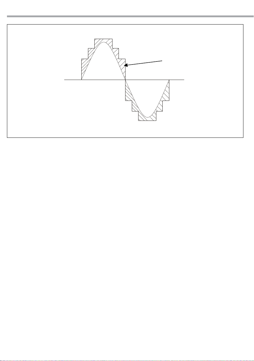
Il diagramma della forma d’onda del segnale di
uscita e il corrispondente valore di tensione applicato è riportato nella gura seguente.
Class I
As mentioned above, the best eciency of Class H
is around 76%. We need to make improvement to
make super high power amplier. But how to do?
Based on the theory, Class H, the extension of Class
AB, divides the stable power into 2 and 3 steps and
controls the power supply in suitable step to oer
power to the transistor according to the sampling
of audio signal range. You can imagine the manual
transmission car, for which specic speed requiring specic gears. And the diagram of its working
power waveform and audio waveform is as shown
below.
8
TDX3600/7000/9000
The consuming heat of Class H
ENIT
Fig.1
La supercie della zona tratteggiata indica le
perdite in potenza dissipate dai transistors di
uscita sotto forma di calore. Si può dedurre che
più step di tensione si utilizzano, più aumenta
l’ecienza del sistema. Tuttavia, il limite dell’attuale tre step in Classe H è quello di adottare
per l’alimentazione tre condensatori di ltro in
serie. Se ne sono necessari altri, la capacità dello
stadio di l’alimentazione non è proporzionale al
segnale di uscita. Questo problema può essere
risolto solo quando l’alimentazione è regolata
automaticamente con continuità (ad inniti step)
su di un singolo condensatore di alimentazione.
Sulla base di questa idea, è nata la classe I, che
può essere descritta, ritornando all’esempio precedente, come una trasmissione automatica di
velocità senza ingranaggi. Ovviamente, questo
porterà una maggiore ecienza e prestazioni
audio superiori.
Pertanto è stato sviluppato un alimentatore in
PWM (modulazione di larghezza d’impulso) in
classe D, che mira a fornire la modulazione di tensione necessaria ad alimentare lo stadio di uscita
di un amplicatore in classe AB. La scelta di una
elevata frequenza di modulazione, pari 600 kHz,
ore la giusta alimentazione allo stadio nale per
impieghi nella gamma delle audio frequenze.
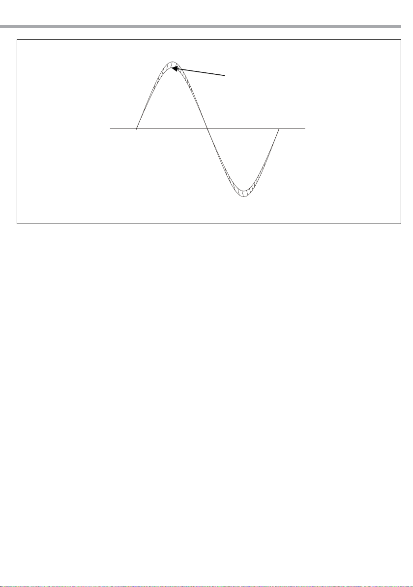
Quindi, l’alimentazione senza gradini segue la
forma d’onda del segnale audio in uscita.
La sua tensione è leggermente superiore al requisito minimo di funzionamento dei transistors di uscita, vale a dire che opera alla tensio-
The hatched area indicates the power dissipated
of the output transistors in the form of heat.
It can be seen that the more gears you divide, the
closer to the required output power it can be, so
as not to make any waste.
However, the current three-staged Class H is to
make the power supply adopt 3 lter capacitors
in series to supply power.
If more is needed, the power supply isn’t in proportion to the actual eect.
And this problem can be solved as long as the
auto-controlled power supply is made.
Based on this idea, Class I is born. We can describe
it as an auto-transmission car changed the speed
not via any gears. Obviously, it will bring higher
eciency and superior sound performance.
We intend to develop a Class D amplier, which
aiming at providing power modulation to the
low and mid frequency band, to drive Class AB
amplier.
Modulation, as high as 600kHz for power source,
can oer desirable power supply to the power
output terminal in the audio range. Thus due
to the power supply without any grading, the
power waveform is changing completely according to the audio waveform. Besides, its voltage
slightly exceeds transistor’s minimum working
requirement, that is to say, the power transistor
operates in the minimum working voltage, resulting in the completely controlled power consumption, to the minimum quantity, together
with the minimum heat quantity. Then the super
TDX3600/7000/9000
The consuming heat of Class I
ENIT
9
Fig.2
ne minima di lavoro, con conseguente quantità
minima di calore dissipato. Elevate potenze di
uscita sono in tal modo facilmente raggiungibili.
La distorsione di crossover e da commutazione di
step sono eliminate.
La capacità totale dei condensatori di alimentazione è sempre interamente impiegata e non
diminuisce al crescere del segnale. La qualità di
riproduzione delle basse frequenze risulta notevolmente aumentata.
L’amplicatore in classe I può essere visto come
un amplicatore analogico alimentato da un amplicatore in classe D.
L’ecienza energetica raggiunge 85%.
large output power can be done. Class I power
amplier is without any switch distortion and
crossover distortion.
The capacitance of lter capacitors can reach
maximum, and the lter eect can reach best,
so that its low frequency power supply can be
guaranteed, outputting abundant energy. In
such situation, the low frequency punch is rather
erce, far away from Class H. Unlike the Class D,
the complete analog amplier is unable to oer
AD and DA transformation process for the music. And from the output stage of Class I, it can
be seen that the Class I amplier is a kind of analog amplier only with digital power supply, still
adopting Class AB and OCL structure. Due to its
high ecient power utilization, the total eciency of Class I reaches over 85%.
10
ELEMENTI DI COMANDO E DI COLLEGAMENTO OPERATING ELEMENTS AND CONNECTIONS
TDX3600/7000/9000
ENIT
6
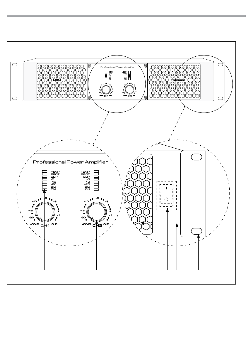
1. FORI DI FISSAGGIO per il montaggio rack
2. MANIGLIE
3. INTERRUTTORE POWER
4. PRESE DI VENTILAZIONE aperture per entrata
usso d’aria da non ostruire.
5. CONTROLLI DI LIVELLO ROTATIVI: potenziometri per l’attenuazione del guadagno d’ingresso. Consentono di attenuare il livello
5
3
1. MOUNTING HOLES for xing the rack
2. HANDLES
3. POWER SWITCH
4. VENTILATION OPENINGS: the openings let the
air ow in. Do not obstruct them.
5. ROTARY LEVEL CONTROL: Input gain attenuator potentiometers. Attenuate the level of the
external signal sent to the respective channels
124
Fig.3Front panel

TDX3600/7000/9000
ENIT
11
del segnale esterno verso i rispettivi canali
dell’amplicatore. La regolazione avviene per
valori continui espressi in dB e compresi tra:
“-80dB”: tutto chiuso (il segnale viene completamente attenuato e, quindi, non viene inviato al canale dell’amplicatore);
“0” : tutto aperto ovvero livello nominale (il
segnale non subisce alcuna attenuazione e,
quindi, viene inviato al canale dell’amplicatore con lo stesso livello con il quale giunge
in ingresso).
- CONTROLLO DI LIVELLO DEL CANALE 1: in
modalità “bridge” questo potenziometro controlla il livello di due canali mentre il canale
2 è inattivo. In modalità “stereo” o “parallelo”
questo potenziometro controlla solo livello
del canale 1. Il range di controllo si estende da
-80 ~ 0dB, con un angolo di rotazione di 280°.
- CONTROLLO DI LIVELLO DEL CANALE 2: in
modalità “bridge” questo potenziometro è
inattivo; il livello è controllato dal potenziometro del canale 1. In modalità “stereo” o “parallelo” il potenziometro controlla solo il livello
del canale 2. Il range di controllo si estende da
-80 ~ 0dB.
6. INDICATORI A LED:
- TEMP (SURRISCALDAMENTO) solo per modello TDX3600/7000: Il Led TEMP si accende
quando la temperatura dei transistor supera i
85°C. Il Led PROT quando la temperatura raggiunge i 130°C. (Far riferimento a“ Sistema di
rareddamento e protezione termica”).
- PROT (PROTEZIONE): si accende quando l’amplicatore va in modalità di protezione. Può
indicare molti tipi di protezione, per esempio:
protezione dal surriscaldamento (TDX9000),
segnale non musicale ad alta frequenza (feedback).
- CLIP: quando la distorsione raggiunge circa lo
0,5%, questa spia si accende.
- LIVELLO IN USCITA: consentono di visualizzare
il livello dei rispettivi canali dell’amplicatore.
Sono costituiti da cinque LED corrispondenti
a: -5/ -10/-20dB.
- SIG: si accende quando è presente un segnale
all'ingresso.
- ON (ACCENSIONE): quando acceso, l’amplicatore è alimentato correttamente.
of the amplier. Continuous values, expressed
in dB, varying among:
“-80dB”: fully closed (the signal is completely
attenuated and therefore it is not sent to the
channel of the amplier);
“0”: fully open, i.e. nominal level (the signal is
not attenuated in any way, so it is sent to the
amplier channel at the same level at which it
arrives on input).
- CH1 LEVEL CONTROL: in bridge mode, this
potentiometer controls the level of two channels, the CH2 potentiometer is inactive. In
stereo or parallel mode: this potentiometer
just controls CH1 level. Gain control range:
-80 ~ 0dB, 40 steps control, eective rotation
angle is 280 degrees.
- CH2 LEVEL CONTROL: in bridge mode, this
potentiometer is inactive, the level is controlled by CH1 potentiometer. In stereo or parallel mode, the potentiometer just controls CH2
level. Gain control range: -80 ~ 0dB, eective
rotation angle is 280 degrees.
6. LED INDICATORS:
- TEMP (OVER-HEAT) only for model
TDX3600/7000: The TEMP LED lights up when
transistors temperature exceeds 85°C. The
PROT LED lights up when temperature reaches 130°C. (Refer to “Cooling system and thermal protection”).
- PROT (PROTECTION): When this indicator
is illuminated, the amplier is in protection
status, this includes for example: over-heat
(TDX9000), high frequency self-excitation or
long time whistle.
- CLIP: When this indicator is on, the amplier
has distortion (CLIP). The distortion is about
0,5%.
- OUTPUT LEVEL: Allow to monitor the level of
the respective channels of the amplier. The
output level indicator includes ve LEDs: -5/
-10/-20dB.
- SIG: the led lights up indicates a input singnal.
- POWER ON: : when this indicator is on, the
amplier main power supply is working.
12
TDX3600/7000/9000
ENIT
7
OFF
0
MAINS AC 220V 50Hz 2300W
8
SPEAKON OUT 1
CH1 OUTPUT:1+/1CH2 OUTPUT:2+/2BRG +/-=1+/2-
SPEAKON OUT 2
CH2 OUTPUT:1+/12+/2- NOT IN USE
11
9
10
12
16
14
SENSITIVITY
XLR
1=G
2=+
3= -
Serial No
DAD is trademar k of
MUSIC & LIGHTS
musiclights.it
Manufactured in P.R.C.
19
TDX3600/7000
13
15
17
9
10
SPEAKON OUT 1
CH1 OUTPUT:1+/1CH2 OUTPUT:2+/2BRG +/-=1+/2-
SPEAKON OUT 2
CH2 OUTPUT:1+/12+/2- NOT IN USE
MAINS AC 220V 50Hz 4800W
12 14
XLR
1=G
2=+
3= -
Serial No
DAD is trademar k of
MUSIC & LIGHTS
musiclights.it
Manufactured in P.R.C.
16
SENSITIVITY
BRIDGE
OPERATION MODE
PARALLEL
BRIDGE
STEREO
ON OFF
19
TDX9000
8
11
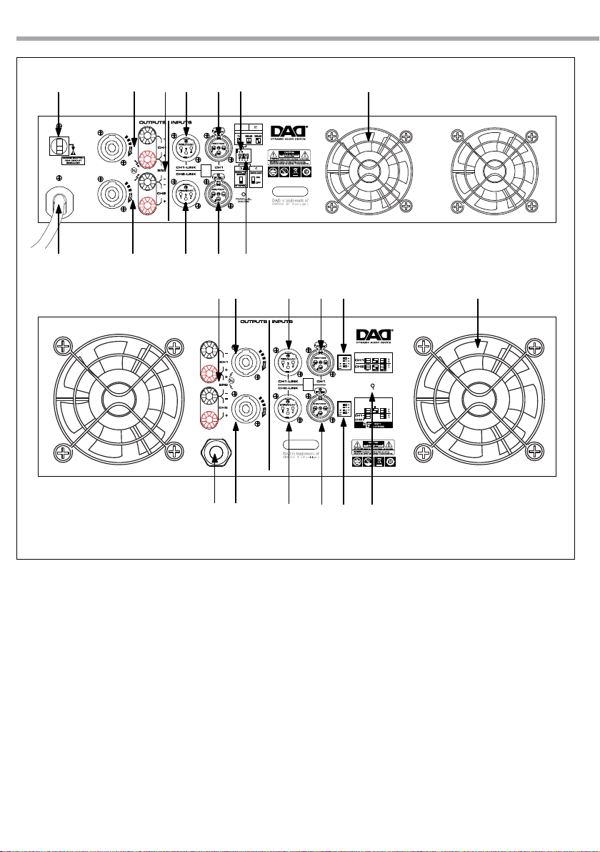
7. FUSIBILE RIARMABILE
8. CAVO DI ALIMENTAZIONE: questo è il cavo
di alimentazione di rete. Collegare l’altra
estremità del cavo di alimentazione ad una
presa di rete elettrica conforme con le speciche di alimentazione riportate sull’apparato
(220V~/50Hz). Assicurarsi che l’amplicatore
sia spento prima di inserire la spina del cavo
nella presa di rete.
9. USCITA CH1 SPEAKON/ MORSETTO:
- SPEAKON Pin 1+/ MORSETTO 1 colore rosso,
collegati all’ uscita POSITIVA del canale 1;
- SPEAKON Pin 1-/ MORSETTO 1 colore nero,
collegati all’uscita NEGATIVA del canale 1;
- SPEAKON Pin 2+/ MORSETTO 2 colore rosso,
collegati all’ uscita POSITIVA del canale 2;
13
15
17 18
7. FUSE BREAKER
8. MAINS CORD: this is the amplier mains supply cable. Connect the power cable to an electrical outlet complying with the power supply specications indicated on the apparatus
(220V~/50Hz).
Be sure your amplier is turned o before you
plug in the mains supply cable into an electrical outlet.
9. CH1 SPEAKON/ BINDING POST OUTPUT:
- Pin 1+ SPEAKON connected to POSITIVE output of channel 1/ BINDING POST red color;
- Pin 1- SPEAKON connected to NEGATIVE output of channel 1/ BINDING POST black color;
- Pin 2+ SPEAKON connected to POSITIVE output of channel 2 / BINDING POST red color;
Fig.4Rear panel

TDX3600/7000/9000
ENIT
13
- SPEAKON Pin 2-/ MORSETTO 2 colore nero,
collegati all’uscita NEGATIVA del canale 2.
Se si collega un cavo standard a due li (1+/1),
si invia all’altoparlante il segnale amplicato
del canale 1.
10. USCITA BRIDGE MORSETTO:
- MORSETTO CH1 colore rosso, polarità positiva;
- MORSETTO CH2 colore nero, polarità negativa.
Questa è l’uscita amplicata del segnale applicato all’ingresso del canale 1 se il selettore dell’amplicatore è impostato in modalità
BRIDGE.
11. USCITA CH2 SPEAKON/ MORSETTO:
- SPEAKON Pin 1+/ MORSETTO 2 colore rosso,
collegati all’uscita POSITIVA del canale 2;
- SPEAKON Pin 1-/ MORSETTO 2 colore nero,
collegati all’uscita NEGATIVA del canale 2;
Questa è l’uscita amplicata del segnaleapplicato all’ingresso del canale 2, se in modalità
STEREO, o del segnale applicato all’ingresso
del canale 1, se in modalità PARALLEL.
12. LINK XLR CH1: connettore XLR maschio connesso in parallelo con il rispettivo connettore XLR femmina di ingresso del canale 1, in
modo da rendere possibile il collegamento in
cascata di una seconda unità.
13. LINK XLR CH2: connettore XLR maschio connesso in parallelo con il rispettivo connettore
XLR femmina di ingresso del canale 2.
14. INGRESSO XLR CH1: connettore XLR femmina
con ingresso bilanciato.
- Pin 1 = schermo o massa;
- Pin 2 = + positivo o “caldo”;
- Pin 3 = - negativo o “freddo”.
NOTA - questo è l’ingresso del canale 1 in modalità STEREO, o l’ingresso di entrambi i canali
1 e 2 in modalità PARALLEL o il solo unico ingresso in modalità BRIDGE.
15. INGRESSO XLR CH2: come sopra, ma per l’ingresso del CH2 è attivo solo in modalità STEREO.
16. INTERRUTTORE GAIN: 1V/38dB/32dB
Impostare il guadagno dell’amplicatore:
- Gain = 1V
Modello TDX9000 - CH2, DIP Switch n°1-2 su
ON-ON
Modello TDX3600/7000 - DIP Switch 1-2 su
OFF-ON
- Gain = 38dB
Modello TDX9000 - CH2, DIP Switch 1-2 su
- Pin 2- SPEAKON connected to NEGATIVE output of channel 2/ BINDING POST black color.
Connecting a standard 2 wire cable (1+/1-),
the speaker receives the amplied output of
the signal applied to channel 1 input.
10. BRIDGE BINDING POST OUTPUT:
- CH1 BINDING POST red color, positive polarity;
- CH2 BINDING POST black color, negative polarity.
This is the amplied output of the signal applied to channel 1 input if the amplier is set
in BRIDGE mode.
11. CH2 SPEAKON/ BINDING POST OUTPUT:
- Pin 1+ SPEAKON connected to POSITIVE output of channel 2/ BINDING POST red color;
- Pin 1- SPEAKON connected to NEGATIVE output of channel 2/ BINDING POST black color;
This is the amplied output of the signal applied to channel 2 input if the amplier is set
in STEREO mode or the signal applied to channel 1 input if the amplier is set in PARALLEL
mode.
12. CH1 XLR LINK: This XLR male connector is connected in parallel with the respective XLR input female connector of channel 1. This enables a second unit (e.g. another amplier) to
be daisy-chained to the rst.
13. CH2 XLR LINK: this XLR male connector is connected in parallel with the respective XLR female connector of Channel 2.
14. CH1 XLR INPUT: XLR female connector with a
balanced line level input.
- Pin 1 = shield or ground;
- Pin 2 = + positive or “hot”;
- Pin 3 = - negative or “cold”.
NOTE - This is the input of Channel 1 in STEREO mode, or the input of both channels 1
and 2 in PARALLEL mode, or the only input in
BRIDGE mode.
15. CH2 XLR INPUT: same as above, but channel 2
operates only in STEREO mode.
16. GAIN SWITCH: 1V/38dB/32dB
Allows the selection of the amplier gain:
- Gain = 1V
TDX9000 model - CH2, DIP Switch No.1-2 turn
to ON-ON
TDX3600/7000 model - DIP Switch No. 1-2
turn to OFF-ON
- Gain = 38dB
TDX9000 model - CH2, DIP Switch No.1-2 turn

14
TDX3600/7000/9000
ENIT
OFF-ON
Modello TDX3600/7000 - DIP Switch 1-2 su
OFF-OFF
- Gain = 32dB
Modello TDX9000 - CH2, DIP Switch 1-2 su
OFF-OFF
Modello TDX3600/7000 - DIP Switch 1-2 su
ON-OFF
NOTA - il guadagno sso a 32dB è una caratteristica standard per l’impostazione di sistemi
complessi di altoparlanti con processore, in
quanto con un gain sso il calcolo dei ltri e
limitatori è semplicato.
17. SELETTORE PARALLEL/BRIDGE/STEREO: permette di determinare la modalità di funzionamento dell’amplicatore.
18. INDICATORE LED
19. PRESE DI VENTILAZIONE: aperture per uscita
usso d’aria da non ostruire.
to OFF-ON
TDX3600/7000 model - DIP Switch No. 1-2
turn to OFF-OFF
- Gain = 38dB
TDX9000 model - CH2, DIP Switch No.1-2 turn
to OFF-OFF
TDX3600/7000 model - DIP Switch No. 1-2
turn to ON-OFF
NOTE - The xed GAIN of 32dB is a useful
feature to set a complex loudspeaker system
using a loudspeaker processor: In fact with a
xed gain the calculation of lters and limiters
is simplied.
17. STEREO/ BRIDGE/ PARALLEL MODE: It selects
the operation mode of the amplier.
18. LED INDICATOR
19. VENTILATION OPENINGS: air ow outlet openings. Do not obstruct them.

TDX3600/7000/9000
ENIT
15
FUNZIONI E IMPOSTAZIONI
FUNZIONI DI PROTEZIONE
Tutti gli amplicatori della serie TDX sono equipaggiati con una serie di ecaci protezioni che
consentono di operare sempre in condizioni di
massima sicurezza.
SISTEMA DI RAFFREDDAMENTO E PROTEZIONE TERMICA
Un sistema di rareddamento altamente sosticato previene qualsiasi inconveniente di natura
termica. Le ventole creano un usso di rareddamento: l’aria entra dalle prese del pannello anteriore attraversa l’intero apparato e deuisce dalle
feritoie del pannello posteriore. Uno speciale dispositivo di controllo termico adatta in maniera
continua la velocità delle ventole in funzione della temperatura rilevata tramite sensori situati sui
dissipatori. Questo tipo di controllo garantisce
che il usso d’aria sia sempre proporzionato alle
condizioni termiche, assicura una maggior silenziosità delle ventole quando l’amplicatore opera con segnali a basso livello e riduce l’accumulo
di polvere all’interno dell’apparato. In condizioni
termiche estreme le ventole forzano un grandissimo volume d’aria. Quando l’amplicatore
funziona a pieno regime per lungo tempo e le
ventole vanno al massimo, se questa condizione
viene mantenuta a lungo, l’amplicatore andrà
in protezione da surriscaldamento e si accenderà
sul pannello frontale la spia “TEMP” di surriscaldamento. Tale protezione fa diminuire la potenza
d’uscita: se infatti la temperatura sale al di sopra
degli 85°C, l’uscita dell’amplicatore diminuirà di
10dB e si accenderà sul pannello frontale la spia
“TEMP” di surriscaldamento. Se la temperatura
continuerà a salire raggiungendo la soglia dei
130°C, sul pannello frontale si accenderà la spia
di protezione “PROT” e non ci sarà più segnale
d’uscita. È sempre necessario che l’utente impieghi l’amplicatore in maniera corretta, non
colleghi carichi inferiori a 2 Ohm e lasci libero il
usso dell’aria di rareddamento a ventola. Fatto questo, non ci dovrebbero essere motivi che
blocchino il segnale d’uscita.
FUNCTIONS AND SETTINGS
RELIABILITY PROTECTION FUNCTION
All the models in the TDX series are tted with
a series of extremely ecient protection, which
ensure they can always be used with the utmost
security.
COOLING SYSTEM AND THERMAL PROTECTION
A highly sophisticated cooling system prevents
any problems of thermal nature.
Four built-in fans, two internal two external,
create a cooling air ow: the front-to-rear owthrough system takes in air through the vents on
the front panel, passes it through the entire unit
and feeds it out through the slits on the back.
A special thermal control device constantly varies fan speed according to the temperature detected by the sensors located on the heat sink.
This type of control ensures that airow always
matches temperature conditions, makes the fan
quieter when the amplier is running with low
signals and reduces the dust build-up inside the
unit.
At high temperatures, the fan is able to drive a
very large amount of air.
When the amplier works at full load and the fan
runs at the highest speed, if this state is kept for a
long time, the amplier probably will go in “overheat” protection.
This protection decreases the output power: in
fact, if the temperature reaches the 85° C threshold, the TEMP LED on the front panel will start
lighting up whilst the amplier’s output will decrease of 10dB. If the temperature doesn’t lower
and keeps on increasing reaching the 130°C, the
PROT protection LED lights up and you will not
have any signal on output. Users must always
operate the equipment correctly, not loading
the amplier with less than 2 Ohms and leave
unobstructed the air ow coming from the cooling system fan. In these conditions, there are no
reason for the amplier to go in over-heat protection and the sound should come out from all
loudspeakers.
NOTA - È possibile ridurre la temperatura riducendo il volume d’uscita.
NOTE - It’s possible to reduce the temperature
reducing the output volume.

16
TDX3600/7000/9000 ENIT
PROTEZIONE IN CORRENTE SUI TRANSISTORS
FINALI
Tutti gli amplicatori della serie TDX hanno la
protezione da corto circuito o da sovraccarico.
Ciò permette ai transistor d’uscita di funzionare
in zona di sicurezza. Se l’amplicatore va in corto,
si accenderà la spia “PROT” sul pannello frontale
e l’amplicatore non emetterà più alcun segnale.
Risolto il problema, la situazione ritornerà alla
normalità in circa 10 secondi.
PROTEZIONE SUI DIFFUSORI
In caso di rottura dei transistors nali o di altre
forme di malfunzionamento che dovessero inviare corrente continua (DC>2,6V) o eccessiva energia subsonica ad una o ad entrambe le uscite di
potenza, l’amplicatore azionerà automaticamente la protezione per proteggere i diusori. In
tal caso, la spia “PROT” si accenderà sul pannello
frontale.
Per proteggere i diusori da pericolosi transienti
o picchi di segnale, invece, le uscite vengono poste in stato di “muting” ogniqualvolta si accende
o si spegne l’amplicatore. Il muting avviene con
le seguenti modalità:
- muting di 10 secondi all’accensione (detto anche ritardo);
- muting istantaneo allo spegnimento.
CURRENT PROTECTION ON THE OUTPUT
TRANSISTORS
All the models in the TDX series have short circuit
and overload protection. It makes the output
transistors work in safety zone.
The PROT protection indicator, on front panel will
light up when output is short circuit, then amplier has no output. If the problem is solved, it
shall automatically recover after 10 seconds.
LOUDSPEAKERS PROTECTION
In the event of output transistor breakdown
or other forms of faulty operations sending
DC>2,6V voltage or excessive subsonic frequencies the amplier will automatically activate the
DC protection to protect the speakers. On the
front panel the PROT protection LED will light up,
while no sound will come out from the speakers.
To protect the loudspeaker enclosures from dangerous transients or signal peaks the outputs are
muted every time the amplier is switched on or
o. Muting takes place as follows:
- 10 seconds muting (also known as “delay”)
when switching on;
- Instantaneous muting when switching o.
PROTEZIONE VHF
Se il segnale in uscita raggiunge un determinato
valore e la frequenza supera i 10kHz, così come
avviene per il feed-back di un microfono per 3 secondi, l’amplicatore andrà in protezione VHF. La
spia “PROT” si accenderanno sul pannello frontale, l’amplicatore non emetterà segnale e i diusori non emetteranno alcun suono. La situazione
si normalizza nel giro di 10 secondi. Se il segnale
non cambierà, l’amplicatore continuerà a rimanere in protezione.
CLIP/ LIMIT
Questa funzione ha due caratteristiche di
protezione:
- Previene la distorsione, non consentendo che
venga superato l’headroom dello stadio di
VHF PROTECTION
If the output signal reaches a certain value and
the frequency exceeds the 10kHz for more than
3 seconds, such as a feed-back sound, the amplier goes in VHF protection. The PROT protection
LED on the front panel will light up, and no output will come out from the amplier as well as
no sound will come out from the speakers. After
having solved the problem, the situation will be
recovered in 10 seconds. If the output signal has
not changed, the amplier will still be in protection.
CLIP/ LIMIT
This feature has two protection functions:
- Limits the input signal range, to prevent input
signal overload from being beyond the amplier rated range. Under this condition the

ENIT TDX3600/7000/9000
17
ingresso.
- In presenza di distorsione da sovraccarico del
segnale in uscita automaticamente limita il
segnale in ingresso.
In entrambi i casi si evita la presenza in uscita
della distorsione armonica (THD) che può
determinare il danneggiamento del diusore.
NOTA - se il segnale di entrata è =+22dBu (10V), il
Clip Limit risulterà inutilizzabile, per questo non
bisogna aumentare in modo illimitato il segnale
sorgente di entrata.
square wave output would cause damage to
the speaker.
- When in presence of a signal waveform distortion, it will automatically adjust gain and limit
distortion signal output.
In both cases the protection features avoid the
harmonic distortion (THD) to be present in the
signal output, this can cause damage to the
loudspeakers.
NOTE - If input signal = +22dBu (10V), clip limit
will also be helpless, so do not increase input
source signal unlimitedly.

18
BINDING POST
CH1 OUTPUT:
SPEAKON 1+1-
BINDING POST
INPUT SIGNAL CH1
TDX3600/7000/9000 ENIT
MODALITÀ DI CONNESSIONE
MODALITÀ STEREO
Modo di connessione:
Impostare la modalità di funzionamento su ‘Stereo’. Con questa predisposizione due segnali
vengono amplicati separatamente dai canali 1
e 2 dell’amplicatore. In altre parole, un segnale
collegato all’ingresso 1 viene amplicato solo dal
canale 1 e inviato alla sola uscita 1. Viceversa un
segnale collegato al canale 2 viene amplicato
solo dal canale 2 e inviato alla sola uscita 2.
ATTENZIONE - Prima di inserire ed estrarre il connettore del segnale di ingresso portare al minimo
il comando del volume per evitare danni causati
dall’impatto del suono agli amplicatori e ai diffusori.
NOTA - Carico minimo 2 Ohm!
SPEAKON OUT 1
CH1 OUTPUT:1+/1CH2 OUTPUT:2+/2-
OFF
0
MAINS AC 220V 50Hz 2300W
BRG +/-=1+/2-
SPEAKON OUT 2
CH2 OUTPUT:1+/12+/2- NOT IN USE
SENSITIVITY
XLR
1=G
2=+
3= -
Serial No
DAD is trademar k of
MUSIC & LIGHTS
musiclights.it
Manufactured in P.R.C.
CONNECTION MODE
STEREO MODE
Connection of this Mode:
Set the amplier operation mode to ‘Stereo’ position. When in this setting, the 2 separate signals
are treated separately by channels 1 and 2 of the
amplier. In other words, a signal connected to
input 1 is only treated by channel 1 of the amplier and only fed to output 1 and a signal connected to input 2 is only treated by channel 2 of
the amplier and only fed to output 2.
ATTENTION - Before inserting and pulling out input signal connection please switch the volume
control to be the minimum position, so as to
avoid that the impact noise damages the ampliers and the speakers.
NOTE - 2 Ohm minimum loading!
TDX3600/7000
CH1 OUTPUT:
SPEAKON 1+1BINDING POST
SPEAKON OUT 1
SPEAKON OUT 2
CH1 OUTPUT:1+/1-
CH2 OUTPUT:2+/2-
BRG +/-=1+/2-
CH2 OUTPUT:1+/1-
2+/2- NOT IN USE
L
R
CH2 OUTPUT:
SPEAKON 1+1-
CH2 OUTPUT:
SPEAKON 2+2-
SIGNAL
LINK
POWER
LINK SIGNAL CH2
LINK SIGNAL CH1
L R
XLR
1=G
2=+
3= -
INPUT SIGNAL CH2
SENSITIVITY
R
L
Fig.5

SPEAKON OUT 1
CH1 OUTPUT:1+/1CH2 OUTPUT:2+/2BRG +/-=1+/2-
SPEAKON OUT 2
CH2 OUTPUT:1+/12+/2- NOT IN USE
MAINS AC 220V 50Hz 4800W
XLR
1=G
2=+
3= -
Serial No
DAD is trademar k of
MUSIC & LIGHTS
musiclights.it
Manufactured in P.R.C.
SENSITIVITY
BRIDGE
OPERATION MODE
PARALLEL
BRIDGE
STEREO
ON OFF
ENIT TDX3600/7000/9000
STEREO
19
TDX9000
CH1 OUTPUT:
SPEAKON 1+1BINDING POST
CH2 OUTPUT:
SPEAKON 2+2-
CH1 OUTPUT:
CH2 OUTPUT:2+
BRG +/-=1+/2-
L
R
SPEAKON OU
CH2 OUTPUT:
2+/2- NOT
CH2 OUTPUT:
SPEAKON 1+1BINDING POST
SIGNAL
LINK
POWER
LINK SIGNAL CH2
LINK SIGNAL CH1
R
L
XLR
1=G
2=+
3= -
Serial No
INPUT SIGNAL CH2
INPUT SIGNAL CH1
SENSI
BRIDGE
OPERATION
PARAL
BRIDGE
ON
L
R
Fig.6

20
CH1 OUTPUT:
SPEAKON 1+1-
BINDING POST
TDX3600/7000/9000 ENIT
MODALITÀ PARALLEL
Modo di connessione:
Impostare la modalità di funzionamento dell’amplicatore su ‘Parallel’.
Con la predisposizione PARALLEL un solo segnale viene amplicato da entrambi i canali 1 e 2
dell’amplicatore. In altre parole, un segnale collegato all’ingresso del canale 1 viene inviato sia
all’uscita 1 che all’uscita 2.
NOTA - Carico minimo 2 Ohm!
SPEAKON OUT 1
CH1 OUTPUT:1+/1CH2 OUTPUT:2+/2-
OFF
0
MAINS AC 220V 50Hz 2300W
BRG +/-=1+/2-
SPEAKON OUT 2
CH2 OUTPUT:1+/12+/2- NOT IN USE
CH1 OUTPUT:
SPEAKON 1+1-
CH2 OUTPUT:
SPEAKON 2+2-
SENSITIVITY
XLR
1=G
2=+
3= -
BINDING POST
Serial No
DAD is trademar k of
MUSIC & LIGHTS
musiclights.it
Manufactured in P.R.C.
PARALLEL MODE
Connection of this Mode:
Set the amplier operation mode to ‘Parallel’ position.
When in this setting, one signal is treated by both
channel 1 and 2 of the amplier. In other words
a signal connected to input 1 is sent to both output 1 and output 2.
NOTE - 2 Ohm minimum loading!
TDX3600/7000
LINK SIGNAL CH1
SPEAKON OUT 1
CH1 OUTPUT:1+/1-
CH2 OUTPUT:2+/2-
BRG +/-=1+/2-
SPEAKON OUT 2
CH2 OUTPUT:1+/1-
2+/2- NOT IN USE
CH2 OUTPUT:
SPEAKON 1+1BINDING POST
SIGNAL
LINK
POWER
SENSITIVITY
XLR
1=G
2=+
3= -
INPUT SIGNAL CH1
Fig.7

SPEAKON OUT 1
CH1 OUTPUT:1+/1CH2 OUTPUT:2+/2BRG +/-=1+/2-
SPEAKON OUT 2
CH2 OUTPUT:1+/12+/2- NOT IN USE
MAINS AC 220V 50Hz 4800W
XLR
1=G
2=+
3= -
Serial No
DAD is trademar k of
MUSIC & LIGHTS
musiclights.it
Manufactured in P.R.C.
SENSITIVITY
BRIDGE
OPERATION MODE
PARALLEL
BRIDGE
ON OFF
ENIT TDX3600/7000/9000
STEREO
PARALLEL
TDX9000
21
CH1 OUTPUT:
SPEAKON 1+1BINDING POST
CH2 OUTPUT:
SPEAKON 2+2-
CH1 OUTPUT:
CH2 OUTPUT:2+
BRG +/-=1+/2-
SPEAKON OU
CH2 OUTPUT:
2+/2- NOT
CH2 OUTPUT:
SPEAKON 1+1BINDING POST
SIGNAL
LINK
POWER
LINK SIGNAL CH1
XLR
1=G
2=+
3= -
Serial No
INPUT SIGNAL CH1
SENSI
BRIDGE
OPERATION
PARAL
BRIDGE
ON
Fig.8

22
TDX3600/7000/9000 ENIT
MODALITÀ BRIDGE
Modo di connessione:
Impostare la modalità di funzionamento dell’amplicatore su ‘Bridge’.
Con la predisposizione “BRIDGE” (ponte) il segnale viene amplicato dai canali 1 e 2 dell’ amplicatore sommati tra loro. In altre parole il segnale
collegato all’ingresso 1 viene:
• amplicato da entrambi i canali di amplicazione sommati tra loro;
• inviato ad un’ unica uscita (Bridge).
La caratteristica di questa predisposizione consiste nel fatto che in uscita si ha un segnale con
potenza e impedenza nominale raddoppiate. Vedere “Speciche tecniche”.
NOTA - Carico minimo 4 Ohm!
SPEAKON OUT 1
CH1 OUTPUT:1+/1CH2 OUTPUT:2+/2-
OFF
0
MAINS AC 220V 50Hz 2300W
BRG +/-=1+/2-
SPEAKON OUT 2
CH2 OUTPUT:1+/12+/2- NOT IN USE
SENSITIVITY
XLR
1=G
2=+
3= -
Serial No
DAD is trademar k of
MUSIC & LIGHTS
musiclights.it
Manufactured in P.R.C.
BRIDGE MODE
Connection of this Mode:
Set the amplier operation mode to ‘Bridge’ position.
With the this setting signal is amplied by the
two sections (1&2) summed together of the amplier summed together. In other words the signal connected to input 1 is:
• amplied by both the amplication sections
summed together;
• fed to a single output (Bridge).
The characteristic of this setting provides a signal
fed out with double the power and rated impedance (see “Technical specications”)
NOTE - 4 Ohm minimum loading!
TDX3600/7000
SPEAKON OUT 1
CH1 OUTPUT:1+/1-
CH2 OUTPUT:2+/2-
BRG +/-=1+/2-
SPEAKON OUT 2
CH2 OUTPUT:1+/12+/2- NOT IN USE
BRIDGE OUTPUT:
SPEAKON 1+2BINDING POST
SIGNAL
LINK
POWER
LINK SIGNAL CH1
XLR
1=G
2=+
3= -
SENSITIVITY
Fig.9

SPEAKON OUT 1
CH1 OUTPUT:1+/1CH2 OUTPUT:2+/2BRG +/-=1+/2-
SPEAKON OUT 2
CH2 OUTPUT:1+/12+/2- NOT IN USE
MAINS AC 220V 50Hz 4800W
BRIDGE OUTPUT:
SPEAKON 1+2BINDING POST
CH1 OUTPUT:
CH2 OUTPUT:2+
BRG +/-=1+/2-
SPEAKON OU
CH2 OUTPUT:
2+/2- NOT
XLR
1=G
2=+
3= -
Serial No
DAD is trademar k of
MUSIC & LIGHTS
musiclights.it
Manufactured in P.R.C.
SIGNAL
LINK
POWER
SENSITIVITY
BRIDGE
OPERATION MODE
PARALLEL
BRIDGE
STEREO
ON OFF
ENIT TDX3600/7000/9000
BRIDGE
LINK SIGNAL CH1
XLR
1=G
2=+
3= -
Serial No
TDX9000
SENSI
BRIDGE
OPERATION
PARAL
BRIDGE
ON
23
Fig.10

24
TDX3600/7000/9000 ENIT
CAVI DI COLLEGAMENTO
COLLEGAMENTI DI INGRESSO
Per il collegamento tra uscite del mixer ed ingressi degli amplicatori utilizzate di preferenza “cavi
segnale bilanciati”. Cavi sbilanciati possono essere
ugualmente usati ma potrebbero dare problemi
di rumore se molto lunghi. In ogni caso, evitate
di usare un cavo bilanciato per un canale e uno
sbilanciato per l’altro, o un cavo bilanciato per
l’ingresso e uno sbilanciato per un rilancio “ Link”
poiché otterreste una sensibile dierenza di livello tra un canale e l’altro.
COLLEGAMENTI DI USCITA
Per il collegamento tra uscite di potenza degli
amplicatori e casse acustiche utilizzate sempre
e solo “cavi di potenza”(cavi per casse acustiche
costituiti da due li di grossa sezione). A tal ne
è opportuno consultare la tabella riportata di seguito per determinare la sezione del cavo in funzione della lunghezza.
NOTA - Abbiate cura dei cavi di collegamento,
aerrandoli sempre per i connettori, evitando
di tirarli lungo il cordone ed avvolgendoli senza
nodi o forti torsioni: ne allungherete la vita e l’afdabilità, a vostro assoluto vantaggio. Vericate
periodicamente che i cavi che impiegate siano
in buono stato, con le connessioni realizzate nel
modo corretto e con tutti i contatti in perfetta efcienza: spesso, infatti, molti problemi ed inconvenienti (falsi contatti, rumori di massa, scariche,
ecc.) sono dovuti unicamente all’utilizzo di cavi
inadatti o avariati.
CONNECTION CABLES
INPUT CONNECTION
To connect the mixer outputs to the ampliers inputs, make sure to always use balanced signal cables. Unbalanced lines may also be used but may
result in noise over long cable runs. In any case,
avoid using a balanced cable for one channel and
an unbalanced one for the other, or a balanced
cable for input and an unbalanced for link, as this
would cause a considerable dierence in channel
levels and/or noise.
OUTPUT CONNECTION
To connect the amplier to the loudspeaker enclosures always use power cables (speaker cables
made up of two wires, normally with a large crosssection). Therefore it is advisable to check the following chart to asses the cable section proportioned with its length.
NOTE - Take care of your connector cables, always gripping them by the plugs, avoid pulling
them directly and winding them without knots or
bends: they will last longer and be more reliable,
which is to your advantage. Check periodically
that your cables are in good conditions, correctly
wired and with perfectly ecient contacts: in fact
many problems and drawbacks (false contacts,
ground hum, crackles, etc.) are caused by the use
of unsuitable or damaged cables.
Perdite di collegamento linee altoparlanti
(massima lunghezza possibile per perdite inferiori a 0,5 dB tensione o spl)
Loudspeaker Line Losses
(maximum permissible line lenghths for 0,5 dB losses, voltage or spl)
4 Ohm load
meter
25
17,5
10
8 Ohm load
meter
50
35
20
Wire section data
2
mm
4,0
2,5
1,5

ENIT TDX3600/7000/9000
25
CONNETTORI
CONNETTORE DI POTENZA SPEAKON
INPUT
OUTPUT 1
2+
channel 2 positive
bridge negative
2+
2-
2-
channel 2 negative
channel 1 negative
1-
1+
channel 1 positive
bridge positive
CONNECTOR
SPEAKON POWER CONNECTOR
SPEAKER POWER OUTPUTS
OUTPUT 2
1-
n.c.
2+
2-
1+
n.c.
1-
1-
1+
1+
channel 2 negative
20mm
0.8"
8mm
0.3"
BLACK
RED
channel 2 positive
CONNETTORE DI SEGNALE XLR XLR SIGNAL CONNECTOR
LINK
1 2
3
INPUT OUTPUT
132
Ground
3
Hot (+)
Hot (+)
Cold (-)
1321 2
Cold (-)
Ground

26
TDX3600/7000/9000 ENIT
MANUTENZIONE
MANUTENZIONE ORDINARIA
Al ne di prevenire l’accumulo di polvere all’interno dell’amplicatore, le aperture frontali per
l’aria dispongono di ltri antipolvere. Ogni volta
che questi ltri sono sporchi (questo dipende dalle condizioni ambientali) si dovranno rimuovere i
ltri usando un cacciavite a stella e pulirli usando
aria compressa o una spazzola leggera.
MANUTENZIONE E RISOLUZIONE DEI PROBLEMI
Qui sotto, sono elencati alcuni semplici metodi
per accertarsi se l’apparecchiatura sia danneggiata o meno.
• Nessun segnale in uscita: se il LED del segnale
è acceso, allora l’amplicatore dovrebbe essere a posto. Controllate se le uscite siano collegate in maniera corretta.
• Basso livello di uscita del segnale: se il LED del
segnale è acceso ed anche quello di CLIP/Limit
lo è, allora controllate che le uscite non siano in
corto. Se il LED del segnale è acceso ed anche
quello di Protezione lo è, allora l’amplicatore
dovrebbe essere in protezione. Ci sono due
possibilità: una è che l’amplicatore sia in surriscaldamento, l’altra è che sia in protezione VHF.
Eliminate il segnale, così potrete constatare se
l’amplicatore è in protezione VHF o no. Se la
temperatura dello chassis è molto alta, molto
verosimilmente l’amplicatore sarà in protezione dal surriscaldamento. Se il voltaggio di
alimentazione è troppo basso, ciò porterà ad
una protezione per mancanza di voltaggio.
• Se i controlli sopra citati non risolvono il problema: rivolgetevi ad un centro di assistenza
autorizzato. L’amplicatore sarà riparato da
tecnici specializzati.
MAINTENANCE
ORDINARY MAINTENANCE
In order to prevent the dust accumulation inside
the amplier, the two air vents on front panel
have a dust lter. Each time these lter area dirty
(it depends on environment conditions) you have
to remove the air slots using a screwdriver and
clean the dust lter using compressed air or a soft
brush.
MAINTENANCE AND TROUBLESHOOTING
Here you are some simple methods to check
whether the equipment is damaged or not.
• No output: If the signal LED lights up, then the
amplier should be ne: please check whether
the output connection port is connected properly.
• Low signal output: If the signal LED lights up
and the clip/limit LED also lights, then please
check whether the output port is shortcircuited or not. If the signal LED lights up and
the protect LED is also lit, then the amplier
should be in protection status. There are two
possibilities: the former is that the over-heat
protection is active, the latter is that the VHF
protection is active. Cut the signal out, then
you can test whether it is VHF protection or
not. If the temperature of chassis is very high,
it should be in overheat protection. If the input
voltage is too low, it could lead to a voltagelacking protection.
• If after the above mentioned check-up, the
malfunction is still not solved: please return
the equipment to an authorized service centre.
It must be repaired by professional repairers.

TDX3600/7000/9000
SPECIFICHE TECNICHE - TECHNICAL SPECIFICATION
TDX3600 TDX7000 TDX9000
8 Ohm stereo power (EIA/THD1%) 850Wx2 1450Wx2 1800Wx2
4 Ohm stereo power (EIA/THD1%) 1350Wx2 2400Wx2 3000Wx2
2 Ohm stereo power (Pulse/THD1%) 1850Wx2 3300Wx2 4500Wx2
4 Ohm bridge power (Pulse/THD1%) 3600W 7200W 9000W
Frequency response 20Hz-20Khz@ 8 Ohm -0.5 dB 20Hz-20Khz@ 8 Ohm -0.5 dB 20Hz-20Khz@ 8 Ohm -0.5 dB
THD N <0.05% <0.05% <0.1%
Slew rate >10V/us >10V/us >10V/us
Damping factor >300 >300 >100
S/N rate >100dB >100dB >90dB
27
Input sensitivity 1V/38dB/32dB 1V/38dB/32dB 1V/38dB/32dB
Voltage gain/8 Ohm 40,5dB 43dB 43,8dB
Input impedance
(balance/unbalance)
Output circuit class I class I class I class
Protection
Cooling air-ow
Power voltage / frequency ~220V 10%/50Hz ~220V 10%/50Hz ~220V 10%/50Hz
Dimensions (WxHxD) 483x89x451 mm 483x89x451 mm 483x133x493 mm
Rack Units 2 2 3
Net Weight 18.20 kg 24.50 kg 32.20 kg
Balance 20K / Unbalance 10K Balance 20K / Unbalance 10K Balance 20K / Unbalance 10K
Clip/limiter, Over-heat, VHF, VLF
Short-circuit, DC, Automatic fade in,
progressive volume
Airow from rear panel to front
panel
Clip/limiter, Over-heat, VHF, VLF
Short-circuit, DC, Automatic fade in,
progressive volume
Airow from rear panel to front
panel
Clip/limiter, Over-heat, VHF, VLF
Short-circuit, DC, Automatic fade in,
progressive volume
Airow from rear panel to front
panel.

28
TDX3600/7000/9000 ENIT
BREVI CENNI DI ACUSTICA
La diusione del suono in un ambiente ha lo scopo di
soddisfare l’ascolto da parte di un certo numero di persone ed è legata a diversi fattori dipendenti dall’ambiente stesso (forma della sala, volume, ecc.), dal numero e dalla posizione degli ascoltatori, dalla natura della
sorgente sonora (esecuzioni musicali o parlato, riprodotti da registrazione o dal vivo) e dal livello di rumore
presente nell’ambiente.
EFFICIENZA
La pressione sonora di un diusore (SPL misurata in dB)
dipende da tre fattori: la sua ecienza, le sue dimensioni ed il suo utilizzo in combinazione con altri diusori.
L’ecienza, cioè la quantità di energia prodotta dall’amplicatore trasformata in suono, determina il volume
che si può ottenere da un amplicatore di una data
potenza. Diusori molto ecienti, possono far sì che un
amplicatore da 50W produca maggior volume di uno
da 100W usato con diusori meno ecienti.
IMPEDENZA
Una delle caratteristiche elettriche di un diusore è l’impedenza ( la resistenza opposta alla corrente alternata).
Sia la resistenza che l’impedenza si misurano in Ohm;
l’impedenza varia al variare della frequenza quindi ne
consegue che le diverse frequenze possono essere rese
con un SPL diverso.
Un diusore con impedenza superiore a quella minima
di funzionamento dell’amplicatore può essere utilizzata a scapito della potenza erogata, mentre è bene evitare collegamenti con diusori che hanno impedenza
minore di quella minima di lavoro dell’amplicatore
di potenza. Usando sistemi più complessi (ad esempio
più speakers collegati allo stesso nale) bisogna fare
in modo che il valore totale dell’impedenza degli altoparlanti sia corrispondente a quella minima di funzionamento del amplicatore. Possiamo avere due tipi di
collegamento: in serie o in parallelo. Collegare in serie
due altoparlanti signica unire un terminale positivo
ed uno negativo dei due e collegare all’amplicatore i
rimanenti due terminali rimasti scollegati. I loro valori si
sommano: per esempio, due altoparlanti da 8 Ohm in
serie danno 16 Ohm.
Quando gli altoparlanti sono collegati in parallelo, i terminali dello stesso segno sono uniti tra loro.
Per ottenere il valore totale bisogna utilizzare una formula, indicando con R1 ed R2 i valori di due altoparlanti,
ed eseguire : (R1 x R2) / (R1 + R2). Con due altoparlanti
da 8 Ohm, per esempio, avremo: (8x8)/(8+8) = 64/16 =
4 Ohm. In pratica collegando due altoparlanti uguali in
parallelo il valore si dimezza. La lunghezza dei cavi di
collegamento deve essere ridotta al minimo necessario.
BRIEF NOTES ON ACOUSTIC
Spreading sound into a room means to distribute sound
signals to a given audience and the results depend on
several environmental factors (room shape, volume,
etc.), the number of people present and their precise
location, the type of sound source (live or recorded music or speech), and the level of the background ambient
noise.
EFFICIENCY
Sound pressure (SPL) of a speaker depends on three
factors: eciency, dimensions and use in combination
with other speakers. Eciency, the quantity of energy
generated by the amplier and transformed into sound,
determines the volume that can be obtainable by an
amplier of a given power rating. A 50W amplier combined with highly ecient speakers may be able to produce a higher volume than a 100W amplier combined
with less ecient speakers.
IMPEDANCE
One of the electrical features of a speaker is its impedance (resistance opposite to the passage of alternate
current). Both resistance and impedance are measured
in Ohm; impedance varies at dierent frequencies so
dierent frequencies can be delivered with dierent
sound pressure levels.
If a loudspeaker has an higher impedance than the
minimal required to the amplier to work properly,
it can be used but this would result in a power reduction; but loudspeakers with an impedance lower than
amplier’s minimum load, must not be connected. If the
systems adopted are more complex (e.g. several speakers connected to the same amplier), you must be sure
that the overall speaker impedance value corresponds
to the amplier output impedance. There are two possible connection systems: serial or parallel mode. Connecting two speakers in series means to connect the
positive pole of the rst speaker to the negative pole of
the second one and then to connect the two free poles
to the amplier. In this case the impedance values are
summed up: e.g. Two 8 Ohm speakers connected in parallel give a 16 Ohm load.
To connect two speakers in parallel mode, simply interconnect the two speakers terminals of the same sign.
To obtain the total value, in this case a calculation is
required. Indicating R1 and R2 as the two loudspeaker
values, the following formula has to be used: (R1 x R2) /
(R1 + R2). E.g.: with two 8 Ohm speakers, we have that:
(8x8)/(8+8) = 64/16 = 4 Ohm, that is to say that when
identical speakers are connected in parallel, the impedance value is halved.

ENIT TDX3600/7000/9000
29
COME SCEGLIERE L’AMPLIFICATORE
La potenza di lungo termine AES, rappresenta la potenza termica dissipabile dal diusore o dai singoli altoparlanti, viene misurata secondo lo standard AES, che
prevede un test di 2 ore con segnale pink noise, fattore
di cresta 2 ; la potenza viene determinata dalla tensione RMS al quadrato divisa per l’impedenza minima del
diusore o del singolo altoparlante. La potenza dell’amplicatore consigliato non viene misurata, ma è pari al
doppio della potenza AES e tiene conto delle capacità
dinamiche degli altoparlanti di sopportare picchi di potenza per brevi istanti di tempo. Il valore fornito corrisponde alla potenza RMS che l’amplicatore deve avere
per fornire il segnale di test ( pink noise con fattore di
cresta 2) usato per misurare la potenza AES.
Un amplicatore con tale potenza, se usato con segnali
musicali con fattore di cresta maggiore o uguale a 6dB,
permette di ottenere il massimo delle prestazioni del
diusore, erogando una potenza di lungo periodo non
superiore a quella AES del diusore. Se, viceversa, si usano segnali musicali molto compressi o il volume viene
alzato no al punto da spingere fortemente in clipping
l’amplicatore, allora, la potenza eettiva di lungo periodo erogata, tende a raggiungere o addirittura superare
quella RMS dell’amplicatore, danneggiando in modo
irreparabile gli altoparlanti. Con questo tipo di segnale
è consigliabile usare un amplicatore con potenza RMS
pari alla potenza AES del diusore, facendo comunque
attenzione a non fornire un segnale di ampiezza tale
da portare troppo spesso in clipping l’amplicatore. La
potenza di breve termine IEC268-5 è la potenza che il
diusore può sopportare per un brevissimo intervallo di
tempo. Corrisponde a 4 volte la potenza AES e viene calcolata in base alla massima tensione di picco che l’amplicatore consigliato può fornire al diusore. Le capacità in termine di SPL nei transitori del segnale musicale,
sono eettivamente corrispondenti a tale valore; quindi
il dato di SPL max fornito nella tabella delle speciche
tecniche viene calcolato in base a tale valore di potenza.
Attenzione: il dato di potenza che eettivamente corrisponde alle capacità termiche del diusore di dissipare
potenza elettrica per lungo periodo è quella AES. Tutti
gli altri dati si riferiscono a “capacità transitorie” del diffusore di accettare potenze correlate con la natura del
segnale audio che sono destinate a riprodurre.
CHOOSING THE RIGHT AMPLIFIER
AES long term applicable power denotes the thermal
power that can be dissipated by the loudspeaker or by
the individual drivers when operated in BI-AMP mode.
This value is measured in accordance with the AES
standard, which involves a 2 hour test with pink noise
signal, crest factor of 2. Power is determined by the
square of the RMS voltage divided by the minimum impedance of the loudspeaker or the individual driver. Although the power of the recommended amplier is not
measured, it is equivalent to double the AES power value and it takes account of the dynamic capacities of the
speakers to withstand short duration power peaks. The
value supplied corresponds to the RMS power required
of the amplier in order to supply the test signal (pink
noise with crest factor 2) utilised to measure AES power.
An amplier of this power, if used with music signals
with crest factor greater than or equal to 6dB, makes it
possible to get the best performance out of the speaker,
delivering along term power output that is no higher
than the AES power of the loudspeaker. On the contrary,
when using highly compressed music signals or if the
amplier volume is increased to the point of intensive
clipping, then the eective long term power tends to
reach or even exceed the RMS output of the amplier,
resulting in irreversible damage to the speakers. With
signals of this type it is always advisable to use an amplier whose RMS output is identical to the speaker AES
power, while taking care to ensure that the signal supplied is such that the amplier is not caused to function
in clipping mode too frequently IEC268-5 short term applicable power corresponds to the power that the loudspeaker can withstand for a very short time interval.
This value corresponds to 4 times the AES power value
and it is calculated on the basis of the maximum peak
voltage that the recommended amplier can supply to
the loudspeaker. Capacities in terms of SPL in transient
components of music signals, eectively correspond to
the short term applicable power value; therefore, the
max. SPL value specied in the technical specications
table is calculated on the basis of this power value Warning: the power value that eectively corresponds to the
thermal capacity of the loudspeaker to dissipate electrical energy over the long term is represented by the AES
value. All other values refer to the “transient capacity”
of the loudspeaker to accept power inputs, correlated
with the nature of the audio signal that the drivers are
destined to reproduce.


"
CERTIFICATO DI GARANZIA
GUARANTEE CERTIFICATE
Place Stamp Here
Arancare
Spett.le
Music&Lights S.r.l.
Via Appia Km 136.200
04020 Itri (LT) Italy
"
The guarantee covers the unit
in compliance with existing
regulations. You can find the
full version of the “General
Il prodotto è coperto da garanzia
in base alle vigenti normative.
Sul sito www.musiclights.it è
possibile consultare il testo
Guarantee Conditions” on our
web site www.musiclights.it.
integrale delle “Condizioni
Generali di Garanzia”.
Abstract
General Guarantee Conditions
Estratto dalle
Condizioni Generali di Garanzia
piece of equipment soon after you
• Please remember to register the
procedere alla registrazione del
• Si prega, dopo l’acquisto, di
purchase it, logging on
www.musiclights.it. The product
prodotto sul sito www.musiclights.it.
In alternativa il prodotto può essere
can be also registered lling in
and sending the form available on
your guarantee certicate.
• Defects caused by inexperience
registrato compilando e inviando il
modulo riportato sul retro.
imperizia e da uso non appropriato
• Sono esclusi i guasti causati da
and incorrect handling of the
equipment are excluded.
eective if the equipment has
been tampered.
• The guarantee will no longer be
• The guarantee makes no provision
dell’apparecchio.
qualora l’apparecchio sia stato
manomesso.
• La garanzia non ha più alcun eetto
sostituzione dell’apparecchio.
• La garanzia non prevede la
for the replacement of the
equipment.
• External parts, loudspeaker,
parti esterne, gli altoparlanti, le
manopole, gli interruttori e le parti
• Sono escluse dalla garanzia le
handles, switches and removable
parts are not included in the
guarantee.
risks are responsibility of the
owner of the equipment.
• Transport costs and subsequent
asportabili.
conseguenti sono a carico del
possessore dell’apparecchio.
• Le spese di trasporto e i rischi
garanzia è avallata unicamente
• A tutti gli eetti la validità della
the guarantee is endorsed solely
on presentation of the guarantee
certicate.
• For all purposes, the validity of
dalla presentazione del certicato di
garanzia.

FORM TO BE FILLED IN AND MAILED / CEDOLA DA COMPILARE E SPEDIRE FORM TO BE FILLED IN AND KEPT / CEDOLA DA COMPILARE E CONSERVARE
"
Purchased by / Acquistato da
Purchasing date
Data acquisto
del Rivenditore
ZIP CODE / C.A.P.
PROV.
CITY / CITTA’
ADDRESS / VIA N.
NAME / NOME
Dealer’s stamp
and signature
Timbro e rma
SURNAME / COGNOME
SERIAL N° / SERIE N°
MODEL / MODELLO
Purchased by / Acquistato da
Purchasing date
Data acquisto
del Rivenditore
ZIP CODE / C.A.P.
PROV.
CITY / CIT Tà
ADDRESS / VIA N.
NAME / NOME
Dealer’s stamp
and signature
Timbro e rma
SURNAME / COGNOME
SERIAL N° / SERIE N°
MODEL / MODELLO


MUSIC & LIGHTS S.r.l.
Via Appia, km 136,200 - 04020 Itri (LT) - ITALY
Phone +39 0771 72190 - Fax +39 0771 721955
www.musiclights.it - email: info@musiclights.it
ISO 9001:2008 Certied Company
DAD è un brand di proprietà della Music & Lights S.r.l. DAD is a brand of Music & Lights S.r.l. company. ©2013 Music & Lights S.r.l.
 Loading...