


PX1000
PX2000
PX3600+
PX5000+
USER MANUAL

2

&217( 176
Contents...........................................................................................................................................................3
Important precautions.......................................................................................................................................4
Safety instructions............................................................................................................................................5
FXQFWLRQ' HVFULSWLRQ.........................................................................................................................................6
Introduction......................................................................................................................................................6
Front panel.......................................................................................................................................................6
Front panel function description ......................................................................................................................7
Rear panel.......................................................................................................................................................8
Rear panel function description...........................................................................................................................9
Reliability - Protection functions........................................................................................................................11
Factory settings...................................................................................................................................11
Installation and operation manual..................................................................................................................12
System connection..........................................................................................................................................12
Basic operation...............................................................................................................................................13
Connection modes and settings.......................................................................................................................14
Maintenance...................................................................................................................................................17
Applicable ranges...........................................................................................................................................17
Replacing a fuse.............................................................................................................................................17
Troubleshooting and maintenance.................................................................................................................17
Schematic diagram.........................................................................................................................................18
Packing list.....................................................................................................................................................19
Specifications.................................................................................................................................................20
Measures.....................................................................................................................................................21
3

IMPORTANT PRECAUTIONS
1. Read all documentation before using your equipment and save it for further reference.
2. Voltage must be correct and the same as that printed on the rear of the unit. Damage
caused by connection to improper AC voltage is not covered by any warranty.
3. Please always use the unit with the AC ground wire connected to the electrical system ground.
Precautions should be taken so that the grounding of a piece of equipment is not
defected.
4. After having connected the amplifier to power supply, “Check” LED lights up indicating that
some components inside already on.
5. When in “bridge mode”, connecting an oscillograph is prohibited: it would cause
damage to the amplifier and to the equipment.
6. The input level of the amplifier must not exceed the marked sensitivity.
7. Do not link the output of any amplifier channel back into another channel 's input. Do not
connect an amplifier output in parallel or series with any other amplifier outputs.
8. In the system setup ,amplifier's output power must be greater 50%-100% than the loaded
loudspeaker's rated power.
9. Make sure that the input signal is compatible with the presetted input settings.
10.Please turn the power off, before pulling off the power cord or the signal cable or before adjusting
the input mode switch.
11.In case of distributing one signal to more than one amplifier, a signal distributor is needed.
12.Please clean the dust filter every 15 days.
13.For a correct operation, please respect the amplifier’s minimum load.
14.In case of malfunction DO NOT try to fix the problem by yourself as it is very dangerous. Please
return your equipment to an authorized service center otherwise any warranty will be null
and void
4

SAFETY INSTRUCTIONS:
CAUTION
Read safety instructions thoroughly before using the amplifier.
Install equipment as follows:
-- Install it on a flat surface, not bending or curved.
-- Do not install it near water or moisture.
-- Place power amplifier away from heat sources, such as radiators or other heat sources.
Keep in mind the following rules when connecting amplifiers
-- Read the user manual before connecting the amplifier
-- Make all connection perfectly. I , it may cause hum,
amplifier’s n case of misconnection
thoroughly
damage or electric shock.
-- To prevent electric shocks, do not open the top cover.
-- Check the AC voltage and amperage before c
onnecting the line cord.
CAUTION
RISK OF ELECTRIC SHOCK
DO NOT OPEN
WARNINGS: DO NOT OPEN !!!
INSIDE THE CASE, SOME COMPONENTS ARE NOT INSULATED AND MAY CAUSE
ELECTRIC SHOCK. IN CASE OF MISFUNCTION, RETURN THE AMPLIFIER TO A
QUALIFIED SERVICE CENTRE.
TO REDUCE THE RISK OF FIRE OR ELECTRIC SHOCK, DO NOT EXPOSE
THIS EQUIPMENT TO RAIN OR MOISTURE.
5

)81&7,2 1 ' ( 6 & 5,37,21
Introduction:
1. This amplifier employs new 3 steps class H power supply circuit, that makes the RMS output power
higher, the operation temperature lower and the product's stability and reliability better.
(Only for PX3600+/PX5000+)
2. Output stage circuit uses a non-traditional transistor emitter follower method that makes the transistor
overloading ability stronger and improves the product's stabilities. (Only for PX3600+/PX5000+)
PX1000-PX2000 front panel
23451
671189 10
PX3600+-PX5000+ front panel
23451
671189 10
6

PX Series front panel function description:
1. Handle
Please use this handle to transport the amplifier.
2. Air Entrance
This part isfor the air entrance. Don't obstruct it.
3. "CLIP" LED
When this indicator lights up, it shows that the output signal reaches the peak, and causes clipping.
In this case, please check the mixer’s output signal and control the output gain. If the general volume is
too high and the clipping status lasts for a long time, the over-drive protection disconnects the loudspeakers
for a bounch of seconds.(PX 3600+ and PX 5000+)
4. "CHECK" LED
When you connect the amplifier to the power supply, this indicator lights up and the amplifier is in stand-by
status. To turn the power on, hold the power button for two seconds.
5. "SIGNAL" LED
This LED indicates the channel’s output level: the brightness changes according to the output level value.
6. Fixing holes:
Plese use these holes to fix the amplifiers into a flight case.
7. Channel 1 Volume Control
If the amplifier operates in stereo or parallel mode, it controls the output level of channel 1. If the amplifier
operates in the “Bridge” mode, it controls the overall output level and the channel 2 volume control is off.
8. "POWER" LED
This indicator lights up when the power amplifier is switched on.
9. Power Switch
Use this switch to turn on/off the amplifier. Keep the power button pressed for 2 seconds and the amplifier
automatically turns on (or off).
10. Channel 1& 2 "PROTECT" LEDs
When these indicators lights up, they show that the power amplifier is in the “protection” status. In this case,
It is necessary to find out and resolve the problem(s) as soon as possible.
The protection status could be caused by :
clip / limiter, over-heat, over-drive (3600+ and 5000+), over-load, short circuit and direct current.
11. Channel 2 Volume Control
If the amplifier operates in stereo or parallel mode, it controls the output level of channel 2. If the amplifier
operates in the “Bridge” mode, this control is off.
7

PX1000-PX2000 rear panel
8742315
CH1 /BRIDGE
OUTPUT
SPEAKON 1:
3
3
3
3
STEREO:1+/1BRIDGE:1+/2+
T8AL 250V
~230V/50Hz 900W
PX3600+-PX5000+ rear panel
10
11
CH1 INPUT CH1 LINK
XLR
PIN 1 =
PIN 2 =
+
PIN 3 =
-
CH2 INPUT CH2 LINK
12 69
896745213
CH1/BRIDGE
OUTPUT
BRIDGE
PARALLEL
STEREO
ONON
OFFOFF
OPERATION
MODE
150
Hz LO-PASS30Hz HI-PASS
GROUNDING
SPEAKON 1:
STEREO:1+/1BRIDGE:1+/2+
CH2 OUTPUT
SPEAKON 2:
STEREO:1+/12+/2- NOT USE
BRIDGE MODE
3
3
SENSITIVITY
0.775V
1.0V
1.4V
ON ON
OFF OFF
LIMITER
3
3
L
O
C
K
L
O
C
K
CAUTION
RISK OF ELECTRIC SHOCK
DO NOT OPEN
RISQUE DE CHOC ELECTRIQUE - NE PAS OUVRIR
ATTEN TIO N:
TO REDUCE THE RISK OF FIRE OR ELECTRIC
WARNING:
SHOCK DO NOT EXPOSE THIS EQUIPMENT TO RAIN OR MOISTURE
CH1
CAUTION:
REPLACE ONLY
WITH SAME
TYPE FUSE!
S
U
E
F
BRG
T20AL 250V
CH2
~230V/50Hz/4800W
PLEASE CLEAN YOUR DUST FILTER EVERY 30 DAYS!
10 11 13 14 15 16 1712
8

PX1000-PX2000 rear panel function description:
1. Channel 1 XLR Input
This XLR input is a balanced input.
2. Channel 1 Link Socket
This balanced socket is used to link another amplifier.
3. Input Sensitivity Selector
This selector allows to choose the input sensitivity among: 0.775V, 1.0V or 1.4V.
4. Operation Mode Selector
Please use this switch to choose among the power amplifier operating modes:
- Stereo Mode: the two channels are completely independent.
- Parallel Mode: Signal input only from channel 1, indipendent volumes on both channels and separated
outputs.
- Bridge Mode: both channels work together to make a very powerful, single-channel monaural amplifier.
Input, volume control and output available on channel 1 only. While working in the bridge mode, a related
LED lights up on the rear panel.
5. Channel 1 Output
Connect this output to a speaker. The branching is: +1, -1 ( except in bridge mode
Speakon
where the branching is: +1, +2 ).
6. Channel 2 Speakon Output
: Connect this output to a speaker. The branching is +1, -1.
7. AC Cord
Plug this cord into the power supply socket. Before using the power amplifier, check if the power
supply is 230V ±10% /50Hz.
8. Air Entrance
This part is the air entrance. Don t obstruct it.'
9. .30Hz high-pass filter switch
This switch, switches on/off the 30Hz high-pass filter. This filter, eliminates the frequencies below 30Hz and
does not make the speaker work at resonance frequency, protecting it effectually.
10. Channel 2 XLR Input
This XLR input is a balanced input
Channel 2 Link Socket
11.
This balanced socket is used to link another amplifier.
12. Grounding Selector
If you want to connect the circuit’s ground with the power supply system grounding, in order to lower hum
or noise, you can switch this selector "ON": in this way they will be interconnected.
9

PX3600+-PX5000+ rear panel function description:
1. Channel 1 XLR Input
This XLR input is a balanced input.
2. Channel 1 bypass socket
It provides the same output signal as the input 1signal.
3. Input Sensitivity Selector
Please use this selector to choose input sensitivity among: 0.775V, 1.0V or 1.4V.
Operation Mode Selector
4.
Please use this switch to choose among the power amplifier operating modes:
- Stereo Mode: the two channels are completely independent.
- Parallel Mode: Signal input only from channel 1, indipendent volumes on both channels and separated
outputs.
- Bridge Mode: both channels work together to make a very powerful, single-channel monaural amplifier.
Input, volume control and output available on channel 1 only. While working in the bridge mode, a related
LED lights up on the rear panel.
Note: Please see the below wiring illustration.
5. 150Hz low-pass filter switch
If the system needs to drive a subwoofer, turn this switch "ON": it filters the signal below 150Hz.
You can use this amplifier to drive subwoofers, without needing an electronic crossover.
6. Channel 1 SPEAKON output
This is the SPEAKON output. 1+ links to speaker’s positive pole and 1- links to speaker’s negative pole.
In the “Bridge” mode, 1+ links to speaker’s positive pole and 2+ links to speaker’s negative pole.
7. Channel 1 binding post output
This is the binding post output. Red color links to speaker’s positive and black color links to the negative.
In the “Bridge” mode, only the red color links to the speaker’s positive pole.
8. Fuse holder
This fuse holder includes a standard fuse specification inside. It is used to protect the amplifier from
damages. If the amplifier is connected to the power supply but the LED doesn’t light up, please check the
fuse. If you find the fuse broken, after troubleshooting, please replace it with another one having the
same features.
9. Air Entrance
This part is the air entrance. Don't obstruct it.
Note: Do not put your hands or anything else into the holes.
10. Channel 2 XLR Input
This XLR input is a balanced input.
11. Channel 2 bypass socket
It provides the same output signal as the input 2 signal.
12. 30Hz high-pass filter switch
This switch, switches on/off the 30Hz high-pass filter. This filter, eliminates the frequencies below 30Hz and
does not make the speaker work at resonance frequency, protecting it effectually.
13. Limiter switch
Use this switch to turn the limiter on/off. Switch it on, to prevent output clipping in consequence of a too
high input signal, so you will avoid damages to the amplifier and the speakers.
14. Grounding Selector
If you want to connect the circuit’s ground with the power supply system grounding, in order to lower hum
or noise, you can switch this selector "ON": in this way they will be interconnected.
15. Channel 2 SPEAKON output
SPEAKON output: 1+ links to the speaker’s positive pole while 1- links to the speaker’s negative one.
16. Channel 2 binding post output
This is the binding post output. Red color links to the speaker’s positive pole while black color links to the
Speaker’s negative one. In the “bridge” mode, only the red color links to the speaker’s negative pole.
17. AC cord
This is the line cord. Before plugging it into an AC outlet, please provide it with a power plug suitable to
to the local socket type.
±10% /50Hz.
Before using the power amplifier, please check out if the power supply is 230V
10

Reliability - Protection function
This amplifier has many protecting functions that give to this product a great reliability.
These protections prevent damages either to amplifier or to loudspeakers.
1. Clip / limiter
When the amplifier output appears to be clipped, to avoid damages to the speakers, a built-in
clip/limiter automatically limits too high input signals. This function can be activated by the switch
placed on the amplifier’s rear panel (PX3600+ and PX5000+ only)
2. Over-heat protection
This equipment works at a rated temperature range (see page 15). If the environment’s temperature
exceeds the rated values or the user employment is not correct, it will cause an internal temperature
increase. In this case, output power is automatically limited until the temperature will be again into its
normal range values.
3. VHF protection (PX3600+ and PX5000+ only)
If a non-musical signal, exceeding audio range, occurs in the input, the amplifier will limit output power
to protect itself and the speakers. Normal output power will be automatically recovered when the VHF
signal is cut off.
4. Short-circuit protection
When a short-circuit occurs on the amplifier’s output (protection limit is below 1 ohm), the amplifier
will limit its output power. It will be automatically recovered as soon as the short-circuit is
removed.
5. VLF protection
If a continuous long-period non-musical signal (VLF), occurs in the input, the amplifier will
automatically attenuate the input signal and limit the output power in order to protect itself
and the speakers. Normal output power will be automatically recovered when the VLF
signal is cut off.
6. DC protection
If the output signal exceeds a rated DC voltage, an output protection function disconnects the load,
to protect the speakers.
7. Automatic “Fade-in” function
When the amplifier starts up or automatically restarts up in consequence of a protection releasing,
the amplifier output level will grow gradually, either to protect the amplifier and speakesr or to allow
the ears’ adaptation.
Factory Settings
1. All volume control was set at "-80" ;
2. Grounding switch was set at "ON" ;
3. Working mode was set at "STEREO" .
4. Sensitivity switch was set at "0.775V .
5. Limiter switch was set at "ON" .
6. Low-pass switch was set at "OFF" . (PX3600+ and PX5000+ only)
7. High-pass switch was set at "OFF" .
11

Installation and operation manual
1. System connection
1.1 While unpacking the package, please check all the provided accessories along with the equipment status.
Usually, it is better save all packing materials.
1.2 PX series cases are designed to fit 2 or 3 standard 19” rack units and are provided with standard fixing holes
on both front and rear panel.
1.3 Connect all wires. (Please make sure that the equipment marked voltage is conform to the local voltage
before connect it to the power supply)
1.4 Signal input/output plug connection mode:
= d XLR balance input/output
2+ input
3-input
1 grounding
=XLR unbalanced input/output
2 signal input
3
1 3connection
1.5 Output plug connection modes:
1 grounding
= Stereo or Parallel mode
Speaker wirings+
Speaker wirings
-
= Bridge mode
Speaker wirings+
1-
1+
2+
1-
2-
1+
Speaker wirings-
CHANNEL 1
Speaker wirings+
Speaker wirings+
CHANNEL 2
Speaker wirings-
Speaker wirings+
Bridge
Speaker wirings-
%/ $&.
RED
RED
%/ $&.
Amplifier output
%/ $&.
RED
Speaker wirings
2-
2+
-
Amplifier output
RED
%/ $&.
12

2. Basic operation
2.1 Switching on
It is opportune to turn channel 1 & 2 volume controls all the way down (-80dB) before switching
the amplifier on. After having inserted the plug into the power outlet, the devices goes in the
stand-by mode, and is ready to work. Press the power button and hold it for 2 seconds:
the amplifier automatically turns on while the “Check” LED switches off and the “Active” LED
lights up in blue.
Notice: When you insert the equipment plug into a power outlet, the amplifier is already
powered and lies in the stand-by mode (”Check LED lights up). If you have not the intention
to use it in a short while, please disconnect the line cord from the power source.
2.2 Switching off
Please adjust the CH1/CH2 volume control all the way down (-80), before switching off the
equipment.
Press the power button and hold it for 2 seconds: the amplifier automatically turns off while the
“Check” LED lights up and the “Active” LED switches off.
13

3. Connection modes and settings
3.1 PX1000-PX2000 stereo mode
CH1
XLR
1+
STEREO
1-
CH1 /BRIDGE
OUTPUT
SPEAKON 1:
3
3
3
3
STEREO:1+/1BRIDGE:1+/2+
T8AL 250V
~230V/50Hz 900W
1+
CH2
XLR
In this mode, connect the CH1 and CH2 inputs to your mixer s outputs.
'
1-
Put the selector on the “Stereo” position.
Output volume can be adjusted by means of the two potentiometers.
Connect the 2 speakon outputs to the 2 speakers.
Parallel mode:
CH1
XLR
PARALLEL
1+
1-
CH1 /BRIDGE
OUTPUT
SPEAKON 1:
3
3
3
3
STEREO:1+/1BRIDGE:1+/2+
T8AL 250V
~230V/50Hz 900W
In this mode, connect the Ch1 to your mixer s outputs.
Put the selector on the “ arallel” position.
P
input '
Outputs volume can be adjusted by means of the two potentiometers.
Connect the 2 outputs to the 2 speakers.
speakon
14
1+
1-

Bridge mode:
CH1
XLR
1+
BRIDGE
2+
CH1 /BRIDGE
OUTPUT
SPEAKON 1:
3
3
3
3
STEREO:1+/1BRIDGE:1+/2+
T8AL 250V
~230V/50Hz 900W
In this mode, connect the input CH1 to your mixer s outputs.
'
Put the selector on the “Bridge” position.
Output volume can be adjusted the channel 1 potentiometer.
by means of
Connect the channel 1 speakon output to the speaker.
3.2 PX3600+-PX5000+ stereo mode
1-
-
L
O
L
O
CAUTION
DO NOT OPEN
C
C
K
K
1+
+
CH1
CAUTION:
REPLACE ONLY
WITH SAME
TYPE FUSE!
S
U
E
F
BRG
T20AL 250V
CH2
~230V/50Hz/4800W
-
+
PLEASE CLEAN YOUR DUST FILTER EVERY 30 DAYS!
(IN)(OUT)
CH1 INPUT CH1 LINK
33
XLR
PIN 1 =
PIN 2 =
+
PIN 3 =
-
33
CH2 INPUT CH2 LINK
Stereo
BRIDGE MODE
SENSITIVITY
0.775V
1.0V
1.4V
ON ON
OFF OFF
LIMITER
PARALL EL
BRIDGE
STEREO
ONON
OFFOFF
OPERATION
MODE
150Hz LO-PASS30Hz HI-PASS
GROUNDING
CH1/BRIDGE
OUTPUT
SPEAKON 1:
STEREO:1+/1BRIDGE:1+/2+
CH2 OUTPUT
SPEAKON 2:
STEREO:1+/12+/2- NOT USE
RISK OF ELECTRIC SHOCK
RISQUE DE CHOC ELECTRIQUE - NE PAS OUVRIR
ATTENTION:
TO REDUCE THE RISK OF FIRE OR ELECTRIC
WARNING:
SHOCK DO NOT EXPOSE THIS EQUIPMENT TO RAIN OR MOISTURE
OR
-
+
(IN)(OUT)
1-
-
+
1+
In this mode, connect the CH1 and CH2 inputs to your mixer s outputs.
'
Put the selector on the “Stereo” position.
Output volume can be adjusted by means of the two potentiometers.
Connect the 2 speakon outputs to the 2 speakers.
15
-
OR
+
+
-

Parallel mode
1-
-
(IN)(OUT)
1+
Parallel
+
OR
-
-
+
+
CH1 INPUT CH1 LINK
33
XLR
PIN 1 =
PIN 2 =
+
PIN 3 =
-
33
CH2 INPUT CH2 LINK
BRIDGE MODE
SENSITIVITY
0.775V
1.0V
1.4V
ON ON
OFF OFF
LIMITER
PARALL EL
STEREO
CH1/BRIDGE
OUTPUT
OPERATION
MODE
BRIDGE
150Hz LO-PASS30Hz HI-PASS
GROUNDING
ONON
OFFOFF
CH2 OUTPUT
SPEAKON 2:
STEREO:1+/12+/2- NOT USE
SPEAKON 1:
STEREO:1+/1BRIDGE:1+/2+
RISK OF ELECTRIC SHOCK
RISQUE DE CHOC ELECTRIQUE - NE PAS OUVRIR
ATTENTION:
TO REDUCE THE RISK OF FIRE OR ELECTRIC
WARNING:
SHOCK DO NOT EXPOSE THIS EQUIPMENT TO RAIN OR MOISTURE
L
O
L
O
CAUTION
DO NOT OPEN
C
K
C
K
1-
CH1
CAUTION:
REPLACE ONLY
WITH SAME
TYPE FUSE!
S
U
E
F
BRG
T20AL 250V
CH2
~230V/50Hz/4800W
-
+
1+
In this mode, connect the Ch1 input to your mixer s outputs.
Put the selector on the “ arallel” position.
P
'
Outputs volume can be adjusted by means of the two potentiometers.
Connect the 2 outputs to the 2 speakers.
speakon
PLEASE CLEAN YOUR DUST FILTER EVERY 30 DAYS!
+
+
-
-
OR
1+
Bridge mode
+
+
(IN)(OUT)
2+
+
Bridge
-
PARALL EL
STEREO
CH1/BRIDGE
OUTPUT
SPEAKON 1:
STEREO:1+/1BRIDGE:1+/2+
OPERATION
MODE
BRIDGE
150Hz LO-PASS30Hz HI-PASS
GROUNDING
ONON
OFFOFF
CH2 OUTPUT
SPEAKON 2:
STEREO:1+/12+/2- NOT USE
'
CH1 INPUT CH1 LINK
XLR
PIN 1 =
PIN 2 =
+
PIN 3 =
-
CH2 INPUT CH2 LINK
BRIDGE MODE
33
SENSITIVITY
0.775V
1.0V
1.4V
ON ON
OFF OFF
LIMITER
33
In this mode, connect the input CH1 to your mixer s outputs.
L
O
C
K
L
O
C
K
CAUTION
RISK OF ELECTRIC SHOCK
DO NOT OPEN
RISQUE DE CHOC ELECTRIQUE - NE PAS OUVRIR
ATTENTION:
TO REDUCE THE RISK OF FIRE OR ELECTRIC
WARNING:
SHOCK DO NOT EXPOSE THIS EQUIPMENT TO RAIN OR MOISTURE
CH1
CAUTION:
REPLACE ONLY
WITH SAME
TYPE FUSE!
S
U
E
F
BRG
T20AL 250V
CH2
~230V/50Hz/4800W
PLEASE CLEAN YOUR DUST FILTER EVERY 30 DAYS!
Put the selector on the “Bridge” position.
Output volume can be adjusted by means of the channel 1 potentiometer.
Connect the channel 1 speakon output to the speaker.
OR
+
-
PLEASE NOTE
In this case (bridge mode), the SPEAKON connection mode is different and in fact:
speaker’s positive pole links to 1+ while the speaker’s negative one links to 2+.
16

Maintenance
1
Application range
1.1 This user manual is suitable only for DAD manufactured PX Series products.
1.2 PX amplifiers are suitable for live performances, band performances, discos, night clubs, etc...
2 Use circumstances
2.1 The room temperature shall be kept around 25 degree while used indoor. It can't be used in
high temperature environments as over heating may cause damages to components.
2.2 If used outdoor, direct exposition to rain or sunshine must be avoided as it would shorten the
equipment's life.
2.3 operation range
A. Environment temperature: -10°C~40°C
B. Relative humidity: Less than 90%
C. Air pressure: 80kPa~106kPa
3 Replacing a fuse
3.1 If the equipment appears affected by a low-grade malfunction and the fuse burns up, after having solved
the problem, replace it with another one of the same type. If the equipment appears affected by severe
damages and causes the fuse to explode, DO NOT replace it, or more severe damages might occur.
In this case, please return the equipment to your dealer for an effective repair.
4 Maintenance and troubleshooting:
Here you are some simple tips to check wether the equipment is damaged or not.
4.1 No output
If the signal LED lights up, then the amplifier should be ok, so , check whether the output
connection is well connected or not.
4.2 Low signal output
If the signal LED lights up and clip LED too, then check whether the output is short-circuited or not.
If the signal LED lights up and the protect LED too, then the amplifier should be in the protection status.
There are two possibilities: the former is that maybe the protection from overheating is active, the
latter is that maybe the VHF protection is active (PX3600+/PX5000+only).
If you take the signal off, then you can test whether it is the VHF protection or not.
If the amplifier case temperature is very hot, it probably should be the overheat protection.
4.3 If after the above mentioned check-up, the problem is still not solved, please return the equipment
to a qualified service centre.
5 Ordinary maintenance
Users must clear the amplifiers regularly, about one time each month. The best way is to use an high pressure
air pump (about 0.8-1.0CBM) and blow air through the air entrance on the front panel or through air exit on
rear panel. Please note that you must never turn the amplifier upside down.
17

Schematic diagram
CHANNEL 1
OUTPUT
AMP FRONT END
Protect
Circuit
CHANNEL 2
OUTPUT
OUTPUT STAGE
AMP FRONT END
ATTENUATOR
NON-INVERTED
ATTENUATOR OUTPUT STAGE
PREAMP
INVERTED
BRIDGE
PAR ALLE L
STEREO
SWITCH
150Hz
Low Pass
30Hz
High Pass
SWITCH
(Only for PX3600+/PX5000+)
NON-INVERTED
PREAMP
INVERTED
XLR-F
3
1
2
INPUT
3
1
2
LINK
XLR-M
1
XLR-M
3
2
LINK
XLR-F
3
1
2
INPUT
18

Packing list
PX1000-PX2000:
Power amplifier x 1 unit
/LQH F RU G x 1pcs
X
1
X
P
2
0P0
X
P
0
00P
2
X
P+0
0
8
3
0
X
0
5
06
+0
00
U
SM
E
S
'
A
N
U
A
LR
PX3600+-PX5000+:
P0
X
1
X
P0
2
0
X
0P
P
0
0
2
X
P
0
8
3
0
X
6
5
0
0
0
+0
0
+
UR
S
E
'
S
M
A
N
U
A
L
User manual x 1pcs's
Power amplifier x 1 unit
User manual x 1pcs's
19
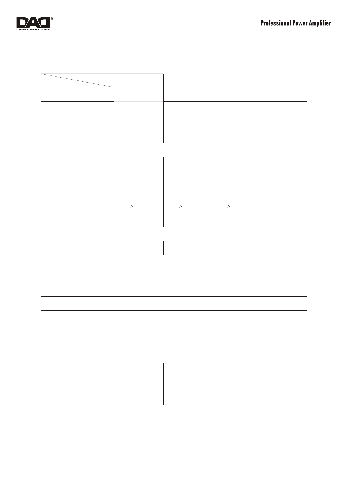
Specications
1. Technical Data
ITEM
MODEL
8 Ohm stereo power
(RMS/THD1%)
4 Ohm stereo power
(RMS/THD1%)
2 Ohm stereo power
(EIA/THD1%)
4 Ohm power
bridge
(EIA/THD1%)
Frequency response
THD+N
(THD%)
Slew rate
Damping factor
Dynamic range
S/N rate
Input Sensitivity
Voltage gai n
PX1000
250Wx2
375Wx2
450Wx2
900W
<0.03%
20V/us
>400
95dB
>90dB
35.2dB
PX2000
520Wx2
780Wx2
936Wx2
1872W
20Hz-20K Hz
<0.03%
30V/us
>400
95dB
>95dB
PX3600+
800Wx2
1200Wx2
1600Wx2
3600W
<0.05%
20V/us
>300
95dB
>95dB
0.775Vrms/1.0Vrms /1.4Vrms
38.4dB
40.2dB
PX5000+
1300Wx2
1950Wx2
2600Wx2
5000W
<0.05%
20V/us
>300
20V/us
>95dB
42.3dB
Input impedance
Output circuit Class
HI-PASS
LO-PASS
Protection
Cooling
Voltage/f requency
Gross Weight
Net Weight
Dimensions
Balance 20K / unbalance 10K
CLASS AB
------
Overheat, Sh ort circ uits , DC, softstart,
Output Relay -Zer o Cu rren t, Clip signal.
Front - to - Rear air ux
~230V 10%/50Hz
23.75Kg 27Kg
30Hz@-3dB
Clip/limiter, ov er-h eat, VHF, short-circui t, DC,
zero current switc h on/o , zero im pact
switch on/o
3 STEPS CLASS H
150Hz@-3dB
36Kg
40Kg
20

2. PX1000-PX2000 dimensions
Front panel
89mm
Rear panel
89mm
33
483mm
CH1 /BRIDGE
OUTPUT
SPEAKON 1:
STEREO:1+/1BRIDGE:1+/2+
T8AL 250V
33
~230V/50Hz 900W
432mm
21

3. PX3600+-PX5000+ dimensions
Front panel
133mm
Rear panel
133mm
CH1 INPUT CH1 LINK
33
XLR
PIN 1 =
PIN 2 =
+
PIN 3 =
-
33
CH2 INPUT CH2 LINK
483mm
BRIDGE MODE
SENSITIVITY
0.775V
BRIDGE
1.0V
PARALLEL
STEREO
1.4V
ON ON
OFF OFF
LIMITER
ONON
OFFOFF
OPERATION
MODE
Hz LO-PASS30Hz HI-PASS
150
GROUNDING
CH1/BRIDGE
OUTPUT
SPEAKON 1:
STEREO:1+/1BRIDGE:1+/2+
CH2 OUTPUT
SPEAKON 2:
STEREO:1+/12+/2- NOT USE
RISQUE DE CHOC ELECTRIQUE - NE PAS OUVRIR
ATTENTION:
TO REDUCE THE RISK OF FIRE OR ELECTRIC
WARNING:
SHOCK DO NOT EXPOSE THIS EQUIPMENT TO RAIN OR MOISTURE
L
O
C
K
L
O
C
K
CAUTION
RISK OF ELECTRIC SHOCK
DO NOT OPEN
CH1
CAUTION:
REPLACE ONLY
WITH SAME
TYPE FUSE!
S
U
F
BRG
T20AL 250V
CH2
~230V/50Hz/4800W
E
PLEASE CLEAN YOUR DUST FILTER EVERY 30 DAYS!
432mm
22

23

 Loading...