

Page 1
!"#$%&%$'(%)*+,'-#,+./0#$(,(),$1'*2#,3%(1).(,'*4,&.-(1#-,*)(%$#5,,6)"4-%21(,7,89:9,/4,;<6=5,<>>,-%21(+,-#+#-?#@5
A)-,B)-#,%*&)-B'(%)*,">#'+#,?%+%(,!!!"#$%&"'()*
&+%,-.%$/*0$0+1
%&2*3454'6(7*3!86'9*:74;<7(=7>))8?=@
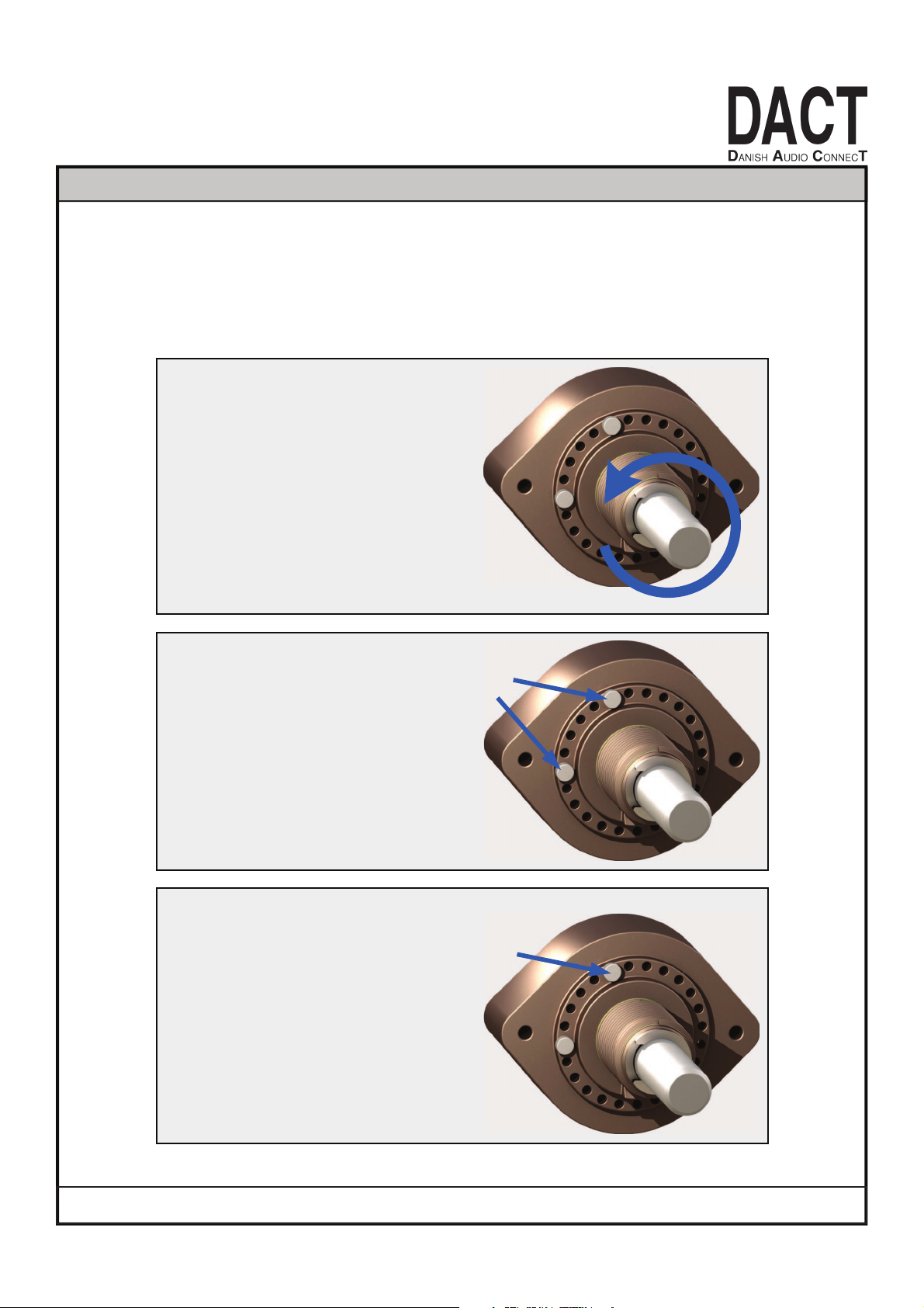
=1#,6=C,(4"#,)&,;<6=,+#>#$()-,+3%($1#+,$'*,/#,B#$1'*%$'>>4,D"-)2-'BB#@E,&)-,@%F#-#*(,*.B/#-,)&,")+%G)*+,
/4,+%B">4,B)?%*2,)*#,+B'>>,+()"H"%*,&-)B,)*#,>)$'G)*,(),'*)(1#-5
I*,2#*#-'>,3#,+1%",'>>,+3%($1#+,3%(1,(1#,+()"H"%*,%*,(1#,")+%G)*J,31#-#,(1#,B'K%B.B,*.B/#-,)&,+3%($1,")+%G)*+,
'-#,)/('%*#@5
,
0
1
2
3
4
5
6
7
8
9
.
.
A&+0*B
L))M%*2, '(, (1#, +3%($1, &-)B, (1#, &-)*(, +%@#,
B'M#, +.-#, (), (.-*, (1#, +1'N, &.>>4, $).*(#-H
$>)$M3%+#, .*G>, (1#, #*@, +()", %+, -#'$1#@5,
A'%>%*2,(),&)>>)3,(1%+,+(#",3%>>,")++%/>#,-#*@#-,
(1#,+3%($1,.*.+'/>#5
A&+0*C
I@#*G&4, (1#, (3), +()", "%*+,
O-%?#(+P, )*, (1#,&-)*(, +%@#, )&,
(1#,%*@#K%*2,B#$1'*%+B5
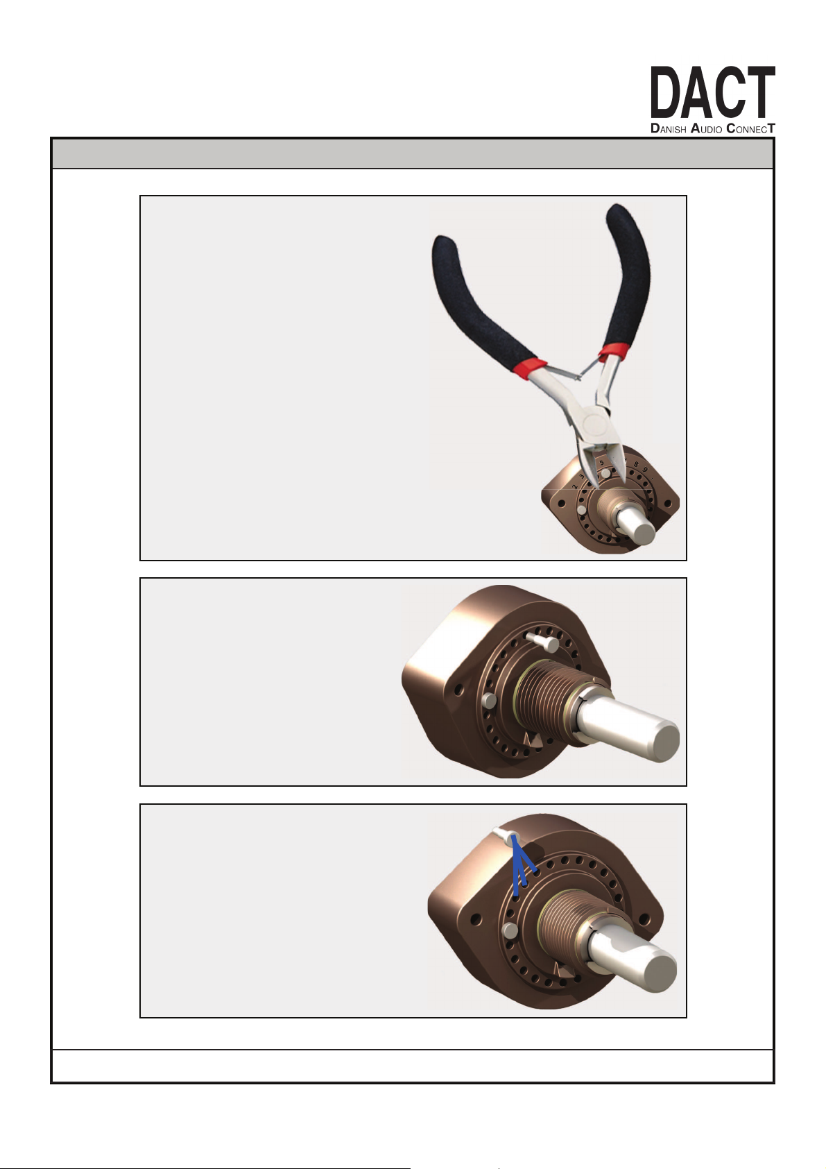
A&+0*2>
QK(-'$(, (1#, $>)$M3%+#HB)+(, -%?#(,
'+, +1)3*5, =1#, +B'>>, -%?#(, @)#+,
('M#, ', /%(, )&, &)-$#, (), -#B)?#5,
R*#, 3'4, %+, .+%*2, ', +B'>>, '*@,
+1'-", 3%-#, $.S#-5, T'M#, +.-#, (),
2#(,', 2))@,U-B,2-%",)*, (1#, 1#'@,
)&,(1#, -%?#(, '*@, +V.##W#, ).(, (1#,
-%?#(5, =1#, 1#'@, )&, (1#, -%?#(, $'*,
/#, @'B'2#@, V.%(#, #'+%>4, +), %(, %+,
%B")-('*(,(),#K(-'$(,%(,%*,(1#,U-+(,
'S#B"(5
Page 2
!"#$%&%$'(%)*+,'-#,+./0#$(,(),$1'*2#,3%(1).(,'*4,&.-(1#-,*)(%$#5,,6)"4-%21(,7,89:9,/4,;<6=5,<>>,-%21(+,-#+#-?#@5
A)-,B)-#,%*&)-B'(%)*,">#'+#,?%+%(,!!!"#$%&"'()*
&+%,-.%$/*0$0+1
%&2*3454'6(7*3!86'9*:74;<7(=7>))8?=@
0
1
2
3
4
5
6
7
8
9
.
.
666
9
A&+0*2B
=1#, +B'>>, -%?#(, @)#+, ('C#,', /%(, )&, &)-$#,
(),-#B)?#5,D*#,3'4,%+,.+%*2,',+B'>>,'*@,
+1'-", 3%-#, $.E#-5, F'C#, +.-#, (), 2#(, ',
2))@,G-B,2-%",)*, (1#, 1#'@, )&, (1#, -%?#(,
'*@,+H.##I#,).(,(1#, -%?#(5, =1#, 1#'@, )&,
(1#, -%?#(, $'*, /#, @'B'2#@, H.%(#, #'+%>4,
+),%(,%+,%B")-('*(,(),#J(-'$(,%(,%*,(1#,G-+(,
'E#B"(5
0
1
2
3
4
5
6
7
8
9
.
.
A&+0*C
K%?#(,#J(-'$(#@5
0
1
2
3
4
5
6
7
8
9
.
.
__
___
___
A&+0*D
L*+#-(,(1#,#J(-'$(#@,-%?#(,%*(),)*#,)&,(1#,
'?'%>'/>#, ")+%M)*+, B)?%*2, %(, $).*(#-N
$>)$C3%+#5, F)?%*2, %(, )*#, ")+%M)*,
'3'4, &-)B, %(+, )-%2%*'>, ")+%M)*,
3%>>, -#@.$#, (1#, *.B/#-, )&, +3%($1,
")+%M)*+,/4,)*#O,'*@,+),)*5
P>'$%*2, (1#, -%?#(, /'$C, %*, '*)(1#-,
")+%M)*, %+, -#>'M?#>4, #'+4O, &)-,
%*+('*$#, /4, '>74EF55G, +H.##I%*2, )-,
1'BB#-%*2,%(5
Page 3

CT3 is a high quality Audio Selector Switch.
It is based on the same high precision, Swiss made switching mechanism as the DACT CT2 audio attenuators.
CT3 is a non-shorting type of switch making sure neither of the input sources will be short-circuiting each other
when the switch is operated.
CT3-5-4/PCB switches t wo channels simultaneously. For both channels it switches signal AND ground. This is an
effective way to minimize the risk of creating ground loops.
In the same way CT3-5-8/wire switches 8 poles.
FEATURES TYPICAL APPLICATIONS
2/4/8-pole switches 2/4/8 channels
simultaneously
Gold plated contacts for long lifetime
even in hot and humid environments
High reliability
Matches perfectly with DACT CT2
audio attenuators
Mechanically “programmable” for 1
to 3 or 5 or 6 postions
Input selector in Do-It-Yourself HiFi / audio projects
Input selector switch in active or
passive preamplifiers
Selector switch in professional audio
equipment
Switch for long lifetime applications
Test equipment selector switch
PRINCIPLES OF OPERATION
CT3-6-2, 6 positions, 2 poles
CT3-3-4, 3 positions, 4 poles
CT3-5-4, 5 positions, 4 poles
CT3-5-8/wire, 5 positions, 8 poles
Page 4

CONNECTIONS, CT3-3-4
Pin no. Connection - example only (input selector)
1 Output, channel 1, signal
2 Input, channel 1, signal, source 1
3 Input, channel 1, signal, source 2
4 Input, channel 1, signal, source 3
5 Output, channel 1, ground
6 Input, channel 1, ground, source 1
7 Input, channel 1, ground, source 2
8 Input, channel 1, ground, source 3
9 Output, channel 2, signal
10 Input, channel 2, signal, source 1
11 Input, channel 2, signal, source 2
12 Input, channel 2, signal, source 3
13 Output, channel 2, ground
14 Input, channel 2, ground, source 1
15 Input, channel 2, ground, source 2
16 Input, channel 2, ground, source 3
17 Input, channel 2, signal, source 4
Seen from the rear side (connector side)
Pin no. Connection - example only (input selector)
1 Output, channel 1, signal
2 Input, channel 1, signal, source 1
3 Input, channel 1, signal, source 2
4 Input, channel 1, signal, source 3
5 Input, channel 1, signal, source 4
6 Input, channel 1, signal, source 5
7 Output, channel 1, ground
8 Input, channel 1, ground, source 1
9 Input, channel 1, ground, source 2
10 Input, channel 1, ground, source 3
11 Input, channel 1, ground, source 4
12 Input, channel 1, ground, source 5
13 Output, channel 2, signal
14 Input, channel 2, signal, source 1
15 Input, channel 2, signal, source 2
16 Input, channel 2, signal, source 3
17 Input, channel 2, signal, source 4
18 Input, channel 2, signal, source 5
19 Output, channel 2, ground
20 Input, channel 2, ground, source 1
21 Input, channel 2, ground, source 2
22 Input, channel 2, ground, source 3
23 Input, channel 2, ground, source 4
24 Input, channel 2, ground, source 5
CONNECTIONS, CT3-5-4
Seen from the rear side (connector side)
CONNECTIONS, CT3-6-2
Pin no. Connection - example only (input selector)
1 Output, channel 1, signal
2 Input, channel 1, signal, source 1
3 Input, channel 1, signal, source 2
4 Input, channel 1, signal, source 3
5 Input, channel 1, signal, source 4
6 Input, channel 1, signal, source 5
7 Input, channel 1, signal, source 6
8 Output, channel 2, signal
9 Input, channel 2, signal, source 1
10 Input, channel 2, signal, source 2
11 Input, channel 2, signal, source 3
12 Input, channel 2, signal, source 4
13 Input, channel 2, signal, source 5
14 Input, channel 2, signal, source 6
Seen from the rear side (connector side)
Page 5

SPECIFICATIONS
MAXIMUM RATINGS
Note Parameter Conditions/comments Value Unit
1 Switching capacity (resistive load) 2V/2A
24V/0.6A
42V/0.4A
AC/DC
1 Operating ambient temp. range
-25 to +70
(-13 to +158)
deg. C
(deg. F)
1 Storage temperature range
-40 to +85
(-40 to 185)
deg. C
(deg. F)
2 Test voltage (contact to contact)
(contact to earth)
1,000
1,000
V
V
MECHANICAL CHARACTERISTICS
Note Parameter Conditions/comments Value Unit
Number of positions CT3-5-4/PCB, CT3-5-8/Wire
CT3-6-2/Wire
CT3-3-4/Wire
1-5
1-6
1-3
Indexing angle CT3-5-4/PCB, CT3-5-8/Wire
CT3-6-2/Wire, CT3-3-4/Wire
15
30
deg.
Switching function
non-shorting
Gold plating, contacts (hard-gold) 3 µm
Gold plating, wiper (hard-gold) 8 µm
3 Mechanical life
>25,000 cycles
Switching torque
8-9 Ncm
Nut tightening torque
max. 300 Ncm
DC ELECTRICAL CHARACTERISTICS
Note Parameter Conditions/comments Value Unit
4 Insulation resistance
(contact to contact)
(contact to earth)
> 10
13
> 10
12
Ohm
Contact resistance (new) max. 0.01 Ohm
Contact capacitance (adjacent contacts) 1 pF
Notes
1 Exposure to maximum rating conditions for extended periods of time may affect dev ice reliability
2 Rms voltage, 50 Hz, 60% relative humidity, applied for 1 minute.
3 One cycle is defined as a full rotation from one end stop to the other and return.
4 Measured with 500 VDC for 1 minute.
ANTISTATIC CHARGES
To avoid noises from antistatic charges we suggest that one of the following two
precautions is taken:
1. The CT3 is mounted with electrical connection between its click-house and
the equipment chassis.
2. A 1 MOhm resistor is connected between the CT3 click-house and equipment
ground.
 Loading...