

Dacor PHG36AG Planning Guide
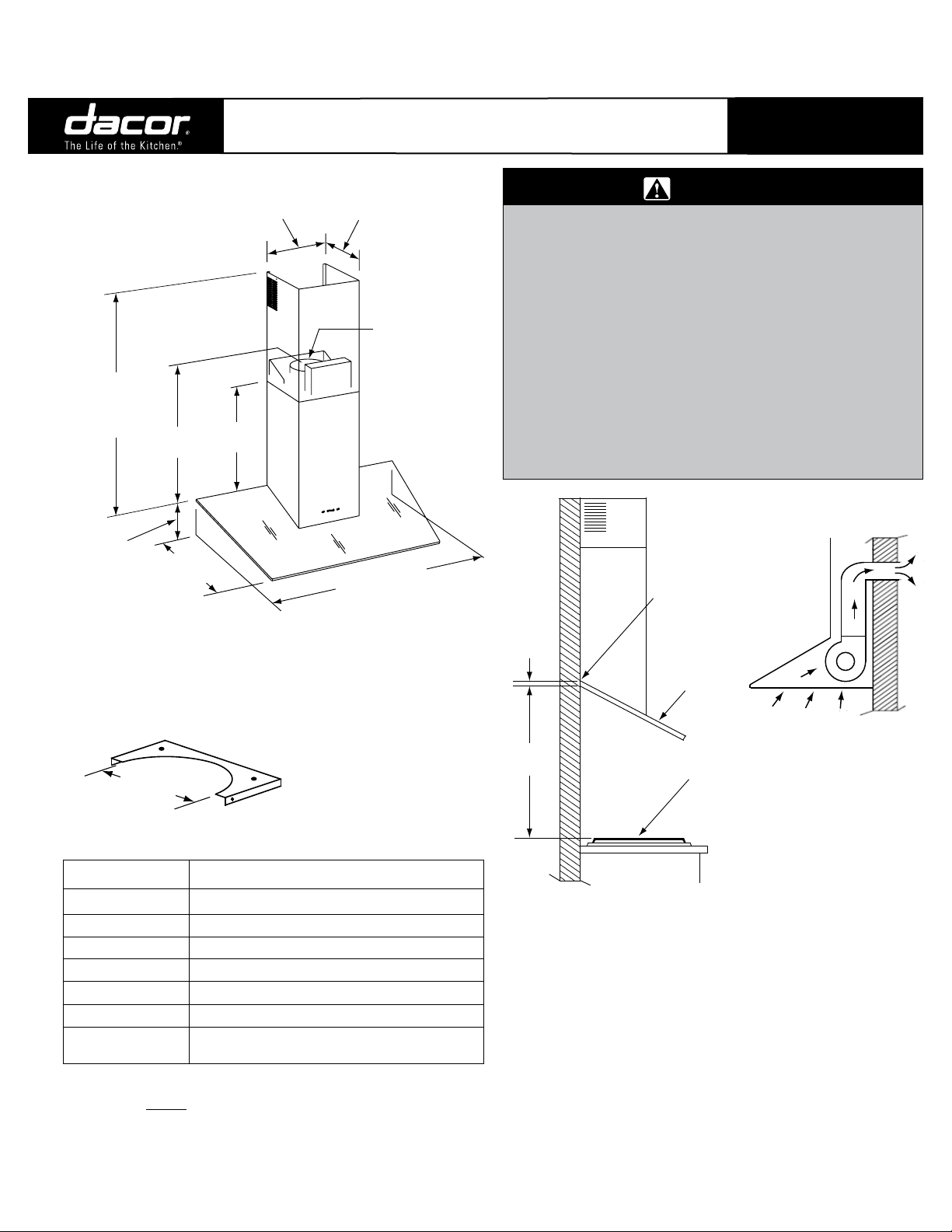
5/16”
(3 mm)
30” Min.
(76.2 cm)
Rear of blower
unit
Cooktop
surface
Glass
5 3/4”
(14.6 cm)
8” Dia.
203.2 cm)
10 3/4” (27.3 cm)
11 7/8” (30.2 cm)
26 1/8” (66.4 cm)
Min.*
44” (111.8 cm)
Max.*
25 3/8” *
(64.5 cm)
19 3/4”
(50.2 cm)
19 3/4” *
(50.2 cm)
30” (76.2 cm) or
36” (91.4 cm)**
* Glass thickness of 5/16” (3 mm) not included
** Glass width and color must be specified at time of order.
Specify glass part number: PHGXXYY where XX is the width
and YY is the color.
8” (20 cm)
Document # PG07 - 003
PHW
Revised 10/21/09 Page 1/1
30 Inch and 36 Inch Wide
Preference® Range Hoods
Product tolerances: ±1/16” (±1.6 mm), -0, unless otherwise stated
PLANNING
GUIDE
WARNING
Observe all governing codes and ordinances during planning •
and installation. Contact your local building department for
further information.
This appliance must be installed in accordance with the •
accompanying installation instructions.
The minimum installed distance from the rear of blower unit •
base to the cooktop surface must be no less than
30” inches (76.2 cm), 26 inches (66.0 cm) for an electric
cooktop. The minimum specified distance may be higher
for the particular range or cooktop in use. Check the
manufacturers specifications for the cooktop or range.
DO NOT install an additional in-line or external blower to •
increase the length of the duct run. Even small differences
between blower air flow rates can greatly reduce the air draw
of the hood.
The hood may exhaust through
the ceiling on through a rear wall.
OVERALL DIMENSIONS
GENERAL SPECIFICATIONS
Blower 600 CFM with electronic speed control
Blower Speeds 4
Lights 120 Vac, 50 Watt halogen (1)
Filters Mesh type, dishwasher safe (2)
Exhaust 8 Inch
Finish 430 stainless steel with tempered glass hood
Power Required 120 Vac, 60 Hz., 3.5 Amp.
Circuit Required
Maximum Duct Length
The maximum straight duct length for the hood is 50 feet. To determine
the actual maximum duct run, subtract the equivalent length of each
elbow, transition and cap from 50 feet. See the Duct Planning Guide or the
installation instructions for more details.
120 Vac, 60 Hz., 15 Amp. 3-wire (hot, neutral,
ground), grounded, dedicated circuit Min.
www.Dacor.com
Phone: (800) 793-0093
CHIMNEY MOUNTING
BRACKET
EXAMPLE OF REAR
EXHAUST
INSTALLATION - SIDE VIEW
Note:
The Dacor color palette has been developed and implemented
throughout our product offerings in order to provide designers and
customers with a coordinating suite of products. All of our Dacor
Preference products compliment the design aesthetic of today's kitchens
as well as one another. Due to the inherent nature of color rendition,
the variation of materials used to assemble these handcrafted products
and manufacturing production tolerances, variation based upon ambient
and natural lighting conditions as well as surrounding surface color
and texture may cause noticeable variation in saturation. These Dacor
products are intended to coordinate with one another and noticeable
differentiation may be apparent if units are installed directly adjacent to
one another.
Specications are subject to change without notice.
See installation instructions for additional details.
7.3
 Loading...