

Page 1
CO
Training Bulletin
DA
DACOR Service Training
The installation of this product includes an on-site handle. Installation is not required and door reversing does not
require drilling. The leveling legs are factory-installed and need only to be adjusted on-site.
The wood fronts on the wire racks can be stained to match the ca
pertinent installation information.
The nomenclature tag is located on the interior ceiling of the unit. T
the unit behind the toekick.
R
New Model Introduction
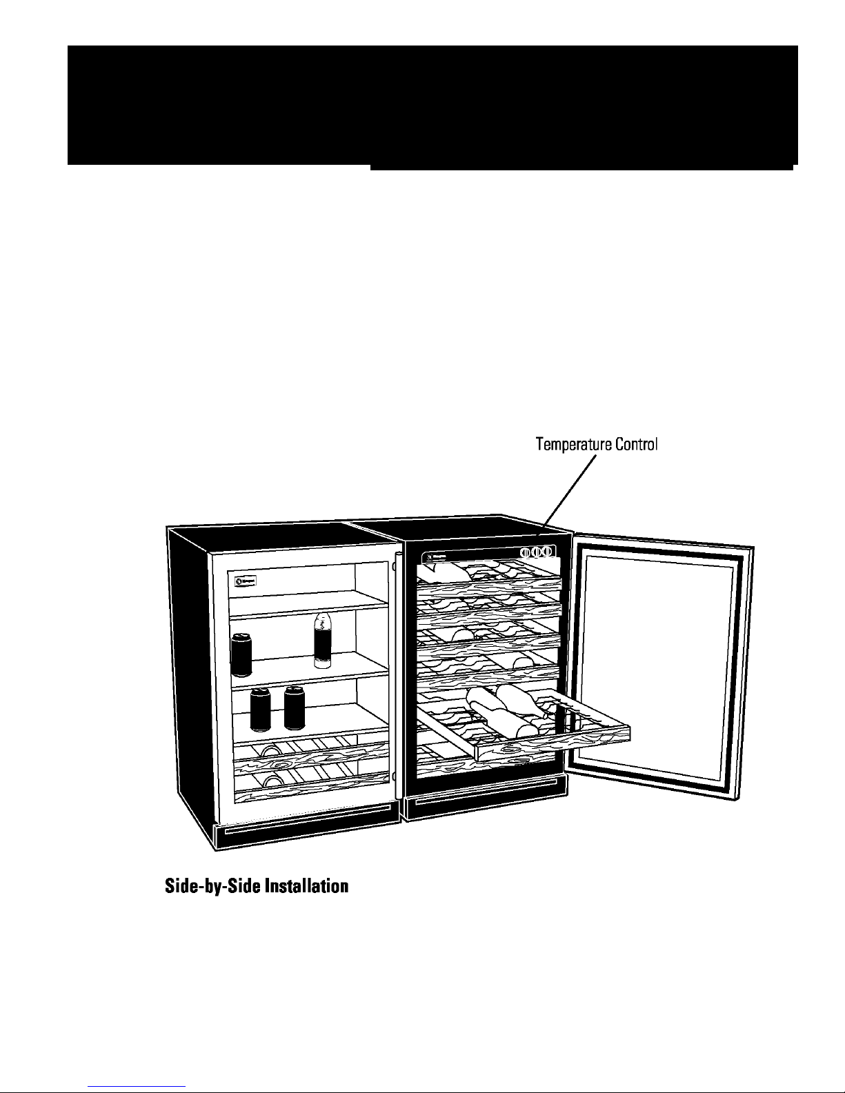
Wine Chiller EWC240
Beverage Center EBC240
binetry. Please read the installation instructions for all
he Mini Manual is taped to the right front corner of
Page 2
Wine Chiller Features
• Total Capacity - 57 Wine Bottles
• 7 Full-Width
Extension Slides
• Upfro
nt, Adjustable Temperature Control
• Interior Li
• Tinted Gla
• Tubula
• Reversibl
• Built-In or Fre
lack Case and Black Toekick
• B
Slide-Out Racks with Wood Fronts on Full-
ght with Automatic or Manual Setting
ss Door with Stainless Trim
r Stainless Steel Handle
e Door Swing
e-Standing Installation Options
Beverage Center Features
• Total Capacity - 133 Beverage Cans, 12 Wine Bottles
• 2 Full-Width
Extension Slides
• 3 Full-Width
Slides
• Upfro
nt, Adjustable Temperature Control
• Interior Li
• Tinted Gla
• Tubula
• Reversibl
• Built-In or Fre
lack Case and Black Toekick
• B
Slide-Out Racks with Wood Fronts on FullGlass Slide-Out Shelves on Full-Extension
ght with Automatic or Manual Setting
ss Door with Stainless Trim
r Stainless Steel Handle
e Door Swing
e-Standing Installation Options
Installation Considerations
The Wine Chiller/ Beverage Center can be installed
either as a built-in or a free-standing unit. The unit may
be closed in on the top and three sides as long as the
front is unobstructed for air circulation and allows proper
access to the door.
A 120 volt 60 Hz, 15 or 20 amp power supply is
required.
or circuit breaker is recommended.
Do not install the unit where the temperature will go
belo
Do not install where it will be subject to direct
sunli
A dedicated, properly grounded, branch circuit
w 55°F (13°C) or above 90°F (32°C).
ght, heat or moisture.
Interior Light Switch
The light switch is located in the upper right front corner
of the unit. When the switch is in the OFF position, the
interior light comes on automatically only when the door
is opened. When the switch is in the ON position the light
will stay on whether or not the door is open.
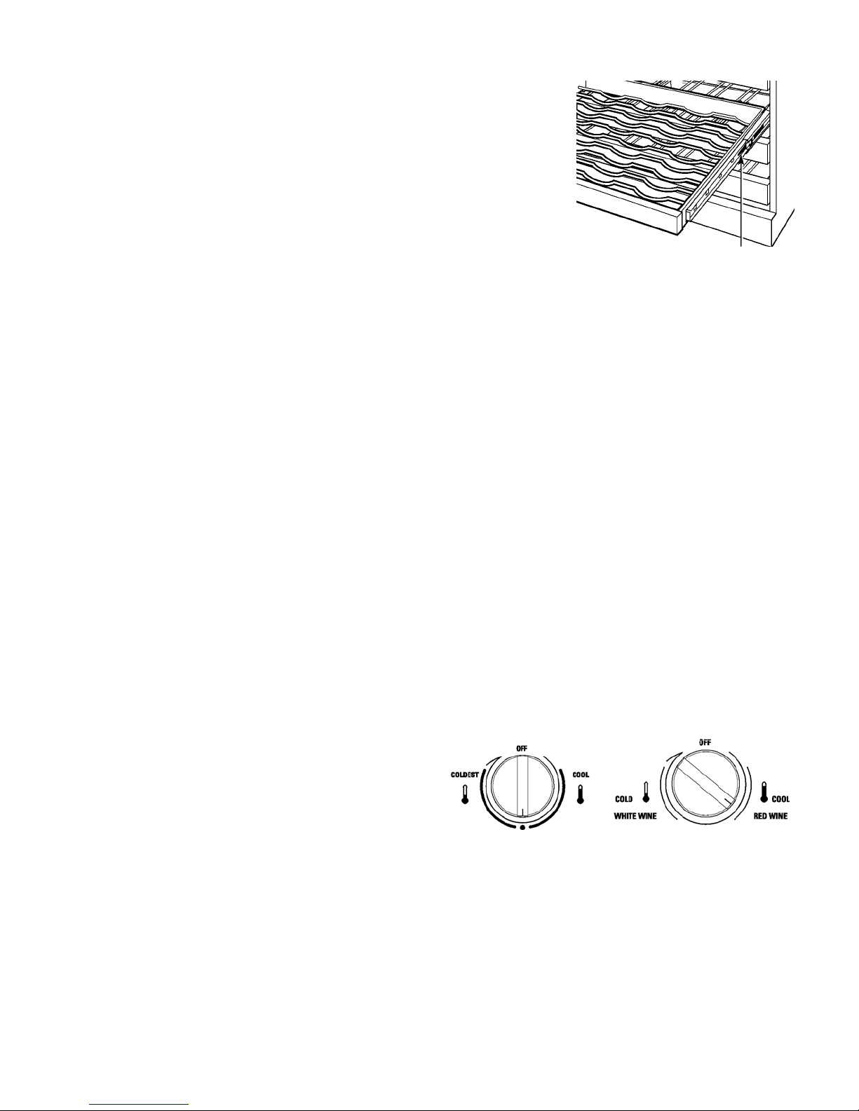
Full-Extension
Sli
des
The full-extension
slides on the racks
and shelve
Wine Chiller and
Beverage Center
allow the
racks/shelves to be
pulled out fully for
easy addition and
removal. Any of the racks/shelves can be removed to store
larger items. To remove the racks/shelves: pull the
rack/shelf out to the STOP position.
Push the tab on the right rack guide
down while pulling the tab on the left
guide up, and pull the rack out. To
replace, insert the sides of the rack/shelf back into the
guides and push until the tabs snap into place. Make
certain the tabs on the rack/shelf are fully engaged before
loading.
s in the
Tab (push tab down on right
rack guide, pull tab up on left
rack guide)
Temperature Control
The temperature control on the new Wine Chiller/Beverage
Center is located in the right front corner of the unit. Both
the Wine Chiller and the Beverage Center deliver colder
temperatures at the bottom of the interior compartment
and warmer temperatures at the top of the compartment.
Normal operating temperatures for the Wine Chiller range
from mid 40°F to mid 60°F. Normal operating temperatures
for the Beverage Center shelves range from low 40°F to
upper 40°F, while the lower racks range from mid 30°F to
mid 40°F. The temperature control also h as an “Off” po sition
when the unit is not in use. To set the control, turn it to the
midpoint setting. Once the unit has been turned on, allow
at least 24 hours before making any adjustments. The cold
control provides total 12°F adjustability nominal. As with
any refrigeration product, there is a slight temperature
variance at different locations within the cabinet.
Wood Fronts on Racks
The wood drawer fronts on the racks of the Wine Chiller/
Beverage Center may be stained to match the
surrounding cabinets. The tinted glass will make the
stained wood appear darker, so a true color match can
only be seen when the door is open.
Evaporator and Drain
The evaporator and the drain are located on the rear wall of
the unit. These are easily accessible for service and
cleaning.
Factory-Installed Handle and Leveling Legs
The door handle and the leveling legs on the Dacor Wine
Chiller and Beverage Center are installed during the
production of the units. On-site installation is not required
for these parts. After installation the unit should be leveled
using the leveling legs and the directions found in the
Installation Instructions.
2
Page 3

Door Reversibility
The door swing of these units can be reversed. The
door swing should be changed before installation.
Refer to the Installation Instructions for further
information on the procedure.
Control Panel
The cold control and light switch are easily replaced by
first removing enough shelves to expose the capillary
bulb retainer clip.
Remove the retainer clip to expose the end of the
capillary. The
plastic sleeve. Carefully pull the capillary through the
sleeve to remove. Remove the two Phillips screws
securing the control panel above. Slide the control
panel forward until the cold control electrical connector
plug is exposed. When reinstalling capillary, make
certain the bulb is captured behind the retaining clip.
thermostat capillary is routed through a
When reinstalling, note the longer screws hold the
retaining cl
control panel.
ip while the shorter screws secure the
Evaporator
The evaporator is foamed into the interior back wall of
the unit and is not serviceable.
Condenser Fan
To access the compressor, relay, overload, run
capacitor, condenser and condenser fan, remove the
machine compartment cover, held by 3 Phillips
screws. The condenser fan is replaced by first
removing two Phillips screws and plastic bushings at
the base of condenser fan bracket.
Slide the bracket, motor, and fan assembly to the left
and out of th
terminals inside compressor cover. When reinstalling
new fan motor, first remove white plastic clips to permit
black rubber bushings to be fully seated.
e unit. Fan wiring is disconnected at
3
Page 4
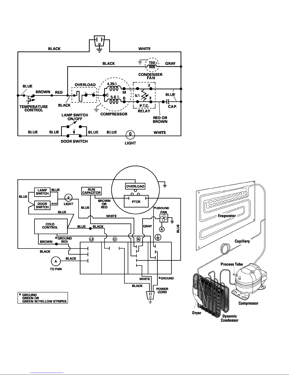
Wiring and Schematic
4
 Loading...