

Page 1
Document # PG04-009
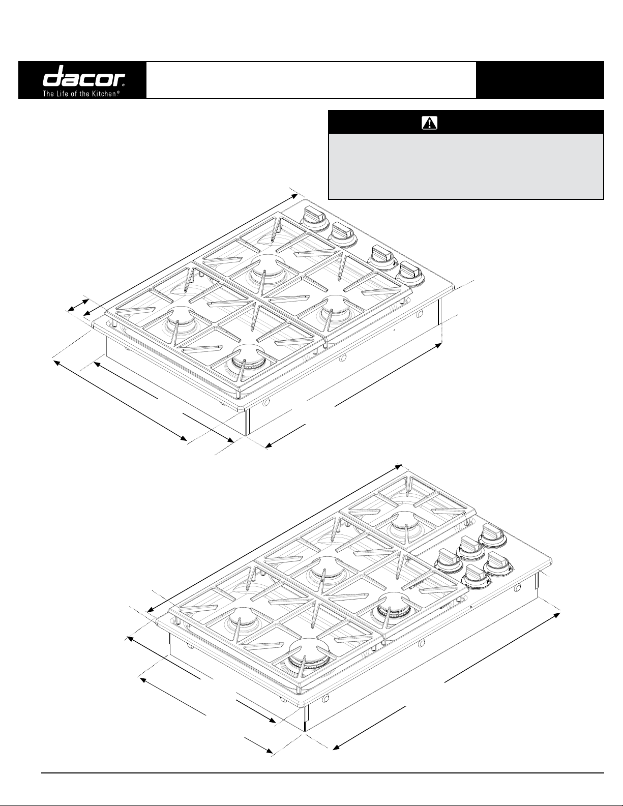
Product tolerances: ±1/16” (±1.6 mm)
unless otherwise noted
DYCT304G
Bottom of spill tray to
top of cooking surface
2 1/8”
(5.4 cm)
30”
(76.2 cm)
DYCT304G, DYCT365G
®
Discovery
Drop-in Gas Cooktops
30” and 36” Wide
• Observe all governing codes and ordinances during planning
and installation.
• Contact your local building department for further information.
• This appliance must be installed in accordance with the
accompanying installation instructions.
Revised 12/14/15 Page 1/4
PLANNING
GUIDE
WARNING
Chassis
height
4”
(10.2 cm)
21”
(53.3 cm)
19 1/2” *
(49.5 cm)
DYCT365G
Bottom of spill tray to
top of cooking surface
2 1/8”
(5.4 cm)
21”
(53.3 cm)
27 1/2” *
* Including raised embosses on sides of chassis
(69.9 cm)
36”
(76.2 cm)
* Including raised embosses on sides of chassis
33 5/8” *
(85.4 cm)
Chassis
height
4”
(10.2 cm)
19 1/2” *
(49.5 cm)
All specications subject to change without notice.
Phone: (800) 793-0093www.dacor.com
4.10
Page 2
Document # PG04-009
Top panel overhang
DYCT304G, DYCT365G
®
Discovery
Drop-in Gas Cooktops
30” and 36” Wide
Revised 12/14/15 Page 2/4
PLANNING
GUIDE
Electrical Requirements
WARNING
To prevent an electric shock hazard, the power supply must meet
the specifications stated below. It is the owner’s responsibility
to make sure that the electrical service meets electrical requirements and that the electrical outlet has been properly installed.
◊ The cooktop is supplied with a factory installed, 40-inch power cord
with a, three-prong, grounding electrical plug. It is connected to the
chassis at the bottom right rear corner (see Chassis Bottom Diagram
below). It must be connected to a dedicated, grounded three-prong
electrical outlet installed by a licensed electrician.
◊ The electrical installation, including minimum supply wire size and
grounding, must be done in accordance with National Electric Code
ANSI/NFPA 70* and local codes and ordinances. A copy of this
standard may be obtained from:
National Fire Protection Association
1 Batterymarch Park
Quincy, Massachusetts 02269-9101
◊ The correct voltage, frequency and amperage must be supplied to
the electrical outlet according to the product data label located on the
bottom of the chassis. See the Gas and Electrical Requirements table
on this page for reference.
◊ Be certain to locate the electrical outlet so that the power may be
easily disconnected if the unit needs service.
Gas Supply Requirements
◊ Be certain that the cooktop being installed is correct for the gas
service being provided (natural gas or LP gas). Also, if operating
the cooktop at an altitude above 4000 ft. (1219 m) make sure it is
equipped for high altitude operation.
◊ Units equipped for LP operation have “LP” in the model number listed
on the product data label. See the Chassis Bottom Diagram for label
location.
◊ Units equipped for high altitude operation have an “H” at the end of
the model number listed on the product data label.
◊ Check your local building codes for the proper method of installation.
In the absence of local codes, this appliance should be installed in
accordance with the National Fuel Gas Code ANSI Z223.1/NFPA 54.
◊ An external manual shut-off valve must be installed between the gas
inlet and the cooktop for the purpose of turning on or shutting off gas
to the appliance.
◊ The cooktop comes from the factory with a regulator in the shipping
carton. Use only the regulator provided. The regulator must be
installed in the gas line that runs from the cooktop gas inlet to the gas
shut off valve.
◊ The regulator inlet accommodates a 3/4” gas line. The inlet to the
cooktop itself is equipped with a 3/4” male NPT fitting.
◊ The electrical and gas data on this page is for reference only. If the
above data does not agree with the product data label, use the data
on the product data label.
◊ The gas supply pressure for testing the regulator setting shall be
at least 1 inch water column (249 Pa) above the specified manifold
pressure.
MODEL
Gas type Natural LPG
Manifold
pressure
Min. gas supply Pressure**
Max. gas supply pressure
Total connected load 0.25 Amp. (0.03 kW) 0.25 Amp. (0.03 kW)
Circuit requirement
GAS AND ELECTRICAL REQUIREMENTS
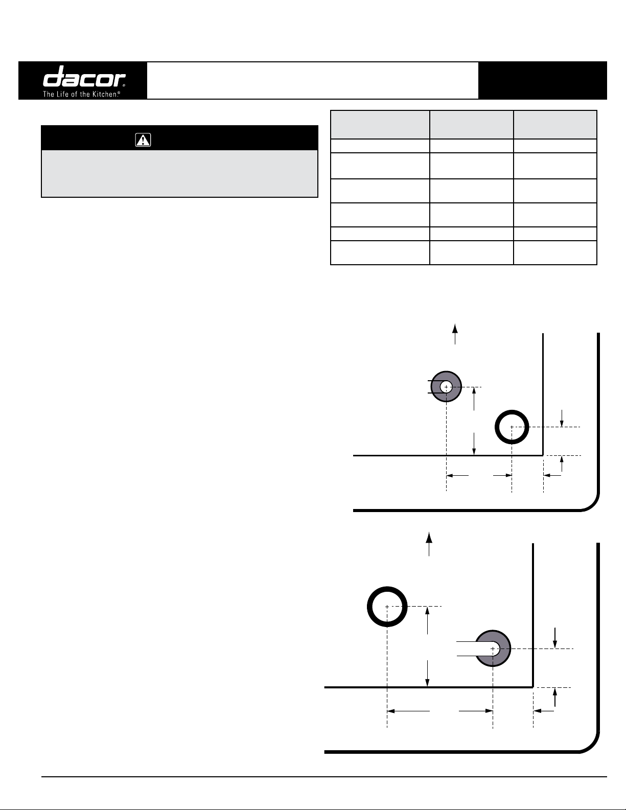
UNDERNEATH
COOKTOP:
DYCT304G
Power cord
Chassis
UNDERNEATH
COOKTOP:
DYCT365G
DYCT304G/NG
DYCT365G/NG
5” Water column 10” Water column
6” Water column 11” Water column
1/2 psi 1/2 psi
120 Vac,
60 Hz, 15 Amp.
Front of cooktop
2 1/8”
(5.4 cm)
3 3/4”
(9.5 cm)
Front of cooktop
Gas inlet
DYCT304G/LP
DYCT365G/LP
120 Vac,
60 Hz, 15 Amp.
5/8”
(1.6 cm)
13/16”
(2.1 cm)
Gas inlet
Power cord in
2 1/4”
Chassis
(5.7 cm)
1 3/8”
(3.5 cm)
1”
1”
(2.5 cm)
(2.5 cm)
All specications subject to change without notice.
Top panel overhang
Phone: (800) 793-0093www.dacor.com
4.11
Page 3

1/4” (6 mm)
min. height clearance
to combustible
surfaces
B
Underneath Cabinet Dimensions
13" max.
(33.0 cm)
A
15" min.
1
(38.1 cm)
1 7/8" min.
(4.8 cm)
Combustible
surface to rear
Combustible overhead
cabinets
30" min.
1, 2
(76.2 cm)
See Note 3
See cutout
dimensions
DYCT304G, DYCT365G
Document # PG04-009
Discovery
Drop-in Gas Cooktops
Cabinet and Countertop Layout
WARNING
• To reduce the risk of personal injury caused by reaching
over a hot appliance, avoid locating cabinet storage space
directly above the cooktop.
• Failure to meet or exceed the maximum and minimum
dimensions/clearances stated in these instructions may
result in a fire hazard.
• Follow the countertop manufacturer’s instructions regarding
the minimum corner radius, use of heat reflective tape,
reinforcement of corners, etc.
◊ Carefully check the location where the cooktop will be installed.
For best performance, the cooktop should be placed away from
drafts that may be caused by doors, windows, and heating and air
conditioning vents.
◊ This appliance is to be used in conjunction with a suitable vent hood
or approved Dacor downdraft vent.
Minimum Required Clearances
Around the Cooktop
Refer to the following illustrations and notes for clearance allowances.
Model (A) Minimum (A) Recommended
DYCT304G 30” (76.2 cm) 36” (91.4 cm)
DYCT365G 36” (91.4 cm) 42” (106.7 cm)
All tolerances: +1/16” -0” unless otherwise noted.
®
30” and 36” Wide
All tolerances: +1/16” -0” unless otherwise noted.
Model
DYCT304G 29 in (73.7 cm)
DYCT365G 35 1/4 in (89.5 cm)
◊ Allow a minimum 1/4” (6 mm) clearance between the bottom of the
cooktop chassis and all combustible surfaces, including the upper
edge of a drawer inside the countertop cabinet below the cooktop.
◊ The gas supply piping, gas shut-off valve, and the electrical outlet
must be located so they do not interfere with the cooktop after it is
installed. If installing another appliance in the cabinet below, allow
for the routing of gas and electrical service behind it.
The installation must allow for the following:
◊ Access to the gas shut-off valve and regulator when the unit is
installed.
◊ The 40-inch (101.6 cm) power cord must be able to reach an
electrical outlet, and that electrical outlet must be easily accessible
after the cooktop is installed.
◊ Access to the underside of the cooktop for service and inspection
purposes.
◊ Clearance inside the counter to allow for correct installation of the
hold-down brackets.
To allow underneath access to the utilities and cooktop bottom, a fixed
shelf should not be installed below the cooktop. See the following pages
for countertop cutout dimensions.
Revised 12/14/15 Page 3/4
PLANNING
GUIDE
(B) Minimum to allow for clearance of hold-down
brackets
1
Measured from the cooking surface (top of cooking grate).
2
If installing an overhead vent hood, check the hood
installation instructions for the minimum required clearance
specifications and requirements.
3
Not required if the side cabinets are at least 6 inches or
more from both sides of the cooktop.
All specications subject to change without notice.
Downdraft Compatibility
If installing the cooktop with a downdraft, use only the approved Dacor
downdraft model numbers below:
Cooktop Models Approved Downdraft Models
DYCT304G ERV3015, PRV30, or RV30
DYCT365G ERV3615, PRV36, or RV36
Phone: (800) 793-0093www.dacor.com
4.12
Page 4

Document # PG04-009
Countertop Cutout View
Countertop Cutout
Dimensions
DYCT304G, DYCT365G
®
Discovery
Drop-in Gas Cooktops
Vertical
combustible
surface
C
1 7/8" min.
(4.8 cm)
30” and 36” Wide
Rear
wall
4 1/4" (10.8 cm) min.
from mounting surface to
combustibles below
cooktop chassis
D
F
Min. distance to combustible side
wall above countertop (both sides)
Revised 12/14/15 Page 4/4
PLANNING
GUIDE
F
E
Configuration Type
DYCT304G with no downdraft 2 7/8” (7.3 cm) 19 3/4” (50.2 cm)
DYCT304G with ERV3015 or PRV30 3/8” (1.0 cm) 22 1/2” (57.2 cm)
DYCT304G with RV30 5/8” (1.6 cm) 22 1/4” (56.5 cm)
DYCT365G with no downdraft 2 7/8” (7.3 cm) 19 3/4” (50.2 cm)
DYCT365G with RV36 5/8” (1.6 cm) 22 1/4” (56.5 cm)
(C) Minimum (D) (E) (F)
All tolerances +1/16” -0” (+1.6 mm) unless otherwise noted.
3/8” min. (1.0 cm)
required for downdraft
cap clearance
Countertop
23 3/8” (59.4 cm)
Stiffener
DYCT Gas Cooktop
Stiffener
Cabinet face
3/8” min. (1.0 cm) space
behind downdraft
to clear stiffener
ERV or PRV Series
Downdraft: check
downdraft specifications
to determine correct fit
27 5/8”
(70.1 cm)
33 3/4” (85.7
cm)
5/8” min. (1.6 cm)
required for downdraft
cap clearance
23 1/8” (58.7 cm)
DYCT Gas Cooktop
Cabinet face
5/8” min. (1.6 cm) space
behind downdraft
to clear stiffener
RV Series Downdraft:
check downdraft
specifications to
determine correct fit
7 1/2”
(19.1 cm)
7” (17.8 cm)DYCT365G with ERV3615 or PRV36 3/8” (1.0 cm) 22 1/2” (57.2 cm)
Countertop
Floor
Cooktop with
Downdraft: ERV/ PRV Series
All specications subject to change without notice.
Floor
Cooktop with
Downdraft: RV Series
Phone: (800) 793-0093www.dacor.com
4.13
 Loading...