

Page 1
Installation Instructions
Heritage Warming Drawers
DWD30, ERWD27, ERWD30, EWD24, EWD27, EWD30,
HWD24PS, HWD27PS, HWD30PS, HWDF30S, IWD24, IWD27,
IWD30, OWD24
Part No. 1113923 Rev A
Page 2
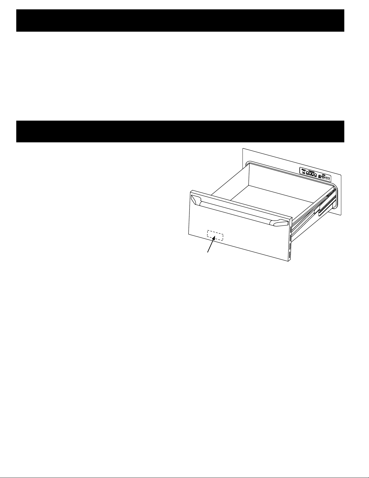
Table of Contents
Important Safety Instructions .......................................... 1
Important Information About Safety Instructions .............. 1
General Safety Precautions ............................................. 1
Installation Specifications ................................................ 2
Verifying the Package Contents ....................................... 2
Installation Planning ......................................................... 2
Installing the Support Platform ......................................... 6
Electrical/Environmental Specifications ........................... 6
Before You Begin...
Important:
Installer: In the interest of safety and to minimize
problems, read these installation instructions completely
and carefully before you begin the installation process.
Leave these installation instructions with the customer.
Customer: Keep these installation instructions for future
reference and the local electrical inspector’s use.
If you have questions or installation/repair/warranty issues,
contact Dacor Customer Assurance. Have available the
drawer's model and serial numbers, which are on the
product data label on the inside front of the drawer.
Dacor Customer Assurance
Phone: 833-35-ELITE (833-353-5483) USA, Canada
M – F 5:00 a.m. to 5:00 p.m. Pacific Time
Website: www.dacor.com/customer-care/contact-us
Installation Instructions .................................................... 6
Removing the Drawer ..................................................... 6
Installing the Chassis ....................................................... 6
Re-installing the Drawer ................................................... 7
Installing the Towel Rack (OWD24 Only) ......................... 7
Verify Function ................................................................. 8
Installation Checklist ........................................................ 8
Product data label on
back for drawer front
All specifications are subject to change without notice. Dacor
© 2018 Dacor, all rights reserved.
®
assumes no liability for changes to specifications.
Page 3
Important Safety Instructions
Important Information About
Safety Instructions
• The Important Safety Instructions and warnings in this
guide cannot cover all possible issues and conditions.
Be sensible and cautious when installing/maintaining/
operating this or any other appliance.
• Always contact the Dacor Customer Service Team about
problems and conditions that you do not understand.
Safety Symbols and Labels
DANGER
Immediate hazards that WILL result in severe personal
injury or death.
WARNING
Hazards or unsafe practices that COULD result in severe
personal injury or death.
CAUTION
Hazards or unsafe practices that COULD result in minor
personal injury or property damage.
General Safety Precautions
To reduce risk of fire, electric shock, serious injury or
death when using your appliance, follow basic precautions,
including the following:
WARNING
• Model OWD24, when installed as a towel warmer, must be
installed indoors and have the supplied wire rack installed in
the drawer bottom according to these instructions.
• Do not install or operate a product that is damaged, has a
damaged power cord or plug, or is malfunctioning in any
manner. Return the appliance to the nearest authorized
service facility for examination, repair or adjustment.
• Make sure that the appliance has been properly installed
and grounded by a qualified installer according to the
accompanying installation instructions. Have the installer
show you the location of the electrical outlet so that you know
where to disconnect power to the appliance.
• Do not repair or replace any part of the warming drawer
unless specifically recommended in the literature
accompanying it. All other service should be done by a
qualified technician.
• Use of accessory attachments not recommended by the
appliance manufacturer may cause injuries.
• Make sure the warming drawer is used only by those
individuals who are able to operate it properly.
• Do not tamper with the controls.
• Never allow anyone, including children to sit, stand or climb
on any part of the appliance, including the drawer. Doing so
may cause tipping, damage, serious injury or death.
• Do not leave children unattended in the area around the
appliance. Do not allow children to operate it, play with the
controls, pull on the handle or touch other parts. Do not
store items of interest to children above the warming drawer.
Children could be burned or injured while climbing on the
appliance.
1
Page 4
Installation Specifications
Verifying the Package Contents
• (3) mounting screws - PN 83569
• Wire rack with mounting hardware (OWD24 only)
(1) PN 83619 (screw), (1) PN 83267 (clamp)
Installation Planning
• A qualified technician must install this built-in appliance.
Proper installation is the customer's responsibility.
• Carefully check the drawer's installation space to ensure
the drawer ia easily accessible and that electrical power
can be provided to the location. Install the warming
drawer in wood cabinets only.
• Plan the installation so all minimum clearances are met/
exceeded. Dimensions shown provide minimum
clearances unless otherwise noted. Ensure the drawer
can be fully opened without impediment.
• The specified minimum cabinet depth and width must be
provided. The cabinet depth and width must completely
enclose the recessed portion of the drawer.
• Cabinet cutout dimensions must be used as indicated. All
contact surfaces between the appliance and the cabinet
must be solid and level. The drawer-support platform
must be flush with the bottom edge of the cabinet cutout.
• Make certain that you have everything necessary to
ensure a proper installation before proceeding.
• A custom front panel is required for IWD series models
and optional for OWD24.
• An optional Epicure
model OWD24.
®
style front panel kit is available for
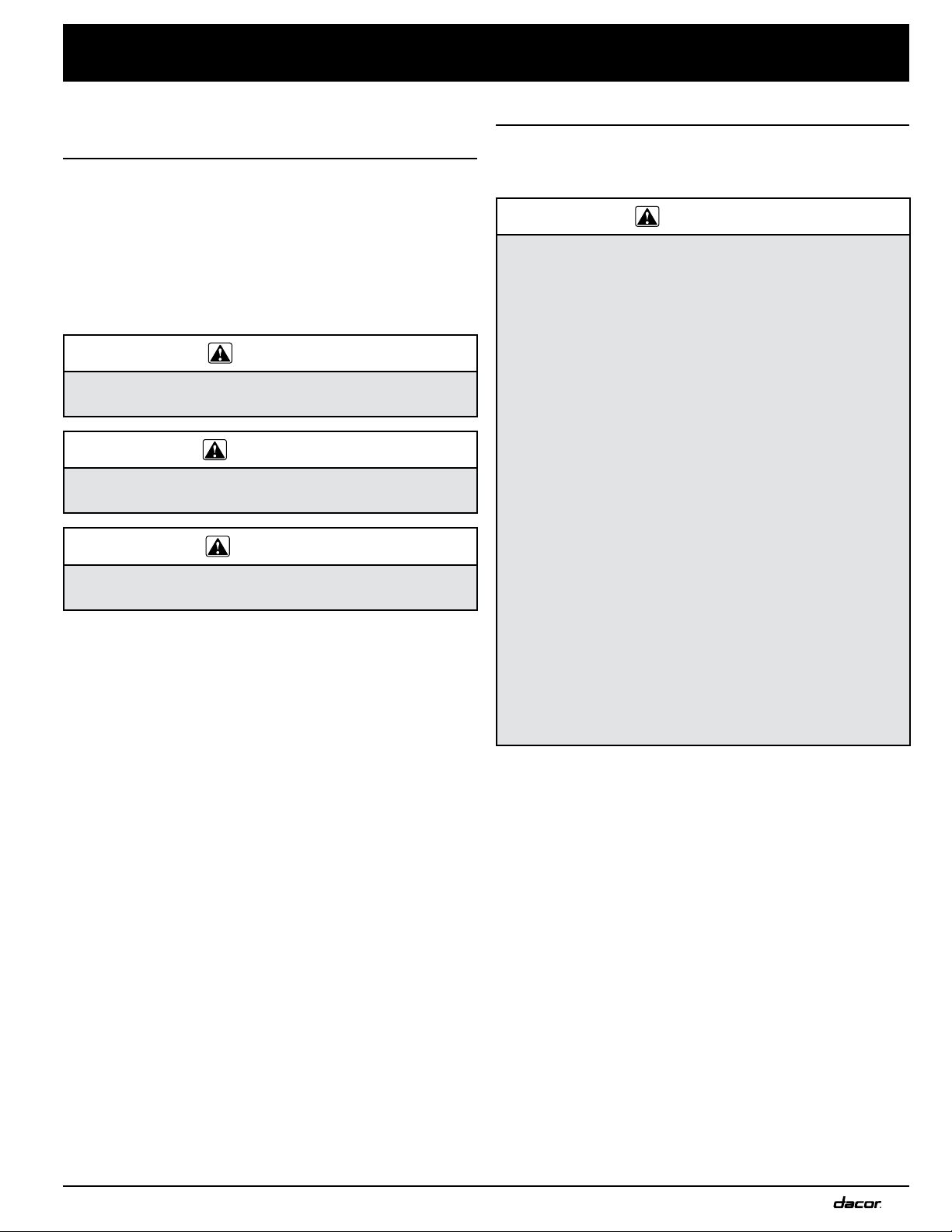
C
B
Chassis
(8 mm)
Drawer open
Overall Dimensions - IWD/OWD Series
Top View
Mounting hole,
9 places
40" (101.6 cm)
3 prong
120 Vac power cord
E
5/16”
F
D
Model
IWD24
IWD27
IWD30
OWD24
**
A
Drawer Face Dimensions
**
**
Chassis without
drawer installed
Chassis Dimensions (IWD/OWD Series)
**
** = OWD24 mounting holes
(IWD/OWD Series)
A (Drawer Face
Width)
22 5/16” (56.7 cm) 22 1/4” (56.5 cm) 22 3/8” (56.8 cm)
25 5/16” (64.3 cm) 25 1/4” (64.1 cm) 25 3/8” (64.5 cm)
28 5/16” (71.9 cm) 28 1/4” (71.8 cm) 28 3/8” (72.1 cm)
22 1/2” (57.1 cm) 22 1/2” (57.1 cm) 22 1/2” (57.1 cm) 11 7/8” (30.2 cm) 20” (50.8 cm) 18” (45.7 cm) 11 7/8” (30.2 cm)
B (Chassis
Width)
C (Chassis Face
Width)
D (Drawer Face
Height)
8 15/16” (22.7 cm) 23 3/8” (59.4 cm) 23 13/16” (60.5 cm) 9 1/16” (23.0 cm)
E (Chassis
Depth)
F (Drawer Depth)
G (Chassis
Height)
See next page for chassis dimensions for other models
G
2
Page 5

Installation Specifications
Drawer face heights are 10 1/8" (25.7 cm) x
width dimension (A); see Warming Drawer
Overall Dimensions table (right) for "A"
dimensions for all drawer models
Warming Drawer Overall Dimensions*
Model (A) Drawer Face Width
EWD24
HWD24PS
ERWD27
EWD27
HWD27PS
DWD30
ERWD30
EWD30
HWD30PS
HWDF30S
*See Pg. 3 for IWD & OWD series chassis dimensions
24” (61.0 cm) 23 5/8” (60.0 cm) 22 1/4” (56.5 cm)
27” (68.6 cm) 26 5/8” (67.6 cm) 25 1/4” (64.1 cm)
30” (76.2 cm) 29 5/8” (75.2 cm) 28 1/4” (71.8 cm)
(B) Chassis Face Width
(C) Chassis Width
Overall Dimensions (top; EWD series shown)
Chassis
Dimensions
HWDxxPS
Handle Dimensions
3
Page 6

B
36" typ.
1 1/2" (3.8 cm)
(91.4 cm)
Cooktop
Installation Specifications
Warming
drawer
Warming
drawer
A
120 Vac
electrical
outlet
Typical countertop
Warming
drawer
C
3/4" min.*
(1.9 cm)
C
D
C
3/4" min.*
(1.9 cm)
3/4” min.*
(1.9 cm)
27"/30"/36" Dacor
single wall oven
Warming
drawer
Warming
drawer
120 Vac
elect.
120 Vac
elect.
Toe kick
A
Cutouts Dimensions
D
C
D
C
3/4" min.*
(1.9 cm)
36" typ.
(91.4 cm)
120 Vac
A
B
electrical
outlet
Model OWD24:
• cannot be installed above/below another
warming drawer of any type.
• is not approved for installation above/below/
adjacent to a wall oven or warming drawer
(incl. another OWD model).
Model (A) Cutout Width
DWD30 28 1/2” (72.4 cm) 30 1/4” (76.8 cm)*
EWD24 22 1/2” (57.2 cm) 24 1/4” (61.6 cm)*
EWD27 25 1/2” (64.8 cm) 27 1/4” (69.2 cm)*
EWD30 28 1/2” (72.4 cm) 30 1/4” (76.8 cm)*
ERWD27 25 1/2” (64.8 cm) 27 1/4” (69.2 cm)*
ERWD30 28 1/2” (72.4 cm) 30 1/4” (76.8 cm)*
HWD24PS 22 1/2” (57.2 cm) 24 1/4” (61.6 cm)*
HWD27PS 25 1/2” (64.8 cm) 27 1/4” (69.2 cm)*
HWD30PS 28 1/2” (72.4 cm) 30 1/4” (76.8 cm)*
HWDF30S 28 1/2” (72.4 cm) 30 1/4” (76.8 cm)*
IWD24 22 1/2” (57.2 cm) **
IWD30 28 1/2” (72.4 cm) **
OWD24**** 22 5/8” (57.5 cm) 24 1/4” (61.6 cm)*** 11 15/16” (30.3 cm) NA 20 1/8” (51.1 cm)
*Bare minimum spacing for ventilation and to avoid scraping on DWD, ERW, EWD models; **IWD models or OWD24 without optional front-panel kit: Chassis and drawer faceplate are
smaller than cutout; custom front panel mounts to drawer faceplate; height and width of custom front panel must exceed cutout dimensions (A, C above) to cover hole; allow 1/4"
minimum added space on top, bottom and sides from the custom front panel edge to prevent scraping against adjacent doors, drawers, and countertop; ***OWD24 with optional
factory front-panel kit only; bare minimum spacing shown to avoid scraping; gap above and below cutout is 3/4” min. (See ** above for OWD24 with custom front panel); ****OWD24
cannot be installed above/below/adjacent to a wall oven or warming drawer of any types.
(B) Min. Width to
Adjacent Doors/Drawers
(C) Cutout Height
9 1/8” (23.2 cm) 1 1/4” (3.2 cm)*
9 1/8” (23.2 cm) 1 1/16” (2.7 cm)IWD27 25 1/2” (64.8 cm) **
(D) Minimum Vertical Gap
Between Cutouts
Minimum Cutout Depth
24” (61.0 cm)
4
Page 7

Installation Specifications
Installing the Support Platform
Provide a platform (100-lb. load capacity) within the cabinet
upon which the warming drawer will be supported; 3/4” (1.9
cm) thick plywood is recommended. The platform must
be installed level and straight. (No provision is made for
leveling the drawer after installation.)
NOTE: If the drawer is installed out of level, it may slide
open on its own or may not seal tightly, thus limiting the
drawer's ability to warm food.
The top edge of the platform must be flush with the cutout
at the front of the cabinet.
Electrical/Environmental
Specifications
WARNING
IMPORTANT: This appliance is equipped with a 3-prong
grounding electric plug for protection against electric
shock. It must be plugged into a dedicated, grounded,
electrical outlet. If only a 2-prong electrical outlet is
available, it is the customer's responsibility to have it
replaced with the appropriate outlet.
To avoid an electric shock hazard, do not under any
circumstances:
• cut/remove the power cord's third (ground) prong
• use an adapter plug
• use a power cord that is frayed or damaged
• immerse the power cord or plug in any type of liquid
• connect the appliance to an extension cord.
NOTE: Using a ground fault interrupter (GFI) is not
recommended.
Chassis
face
Support
platform
• Minimum ambient operating temperature: 32°F (0°C).
• The correct voltage, frequency, and amperage must be
supplied to the electrical outlet from a grounded, singlephase circuit protected by a properly sized circuit breaker
or time-delay fuse.
• The required voltage, frequency, and amperage ratings
appear on the product-data label. (See Pg. II for
location).
Nominal Electrical Supply Requirements
120 Vac, 60 Hz, 15 Amp., dedicated circuit
The warming drawer is supplied with a 40” (101.6 cm)
power cord with a three prong grounded plug.
Total Connected Load 0.5 kW (4 Amp.)
• The above power-supply requirements are for reference
only. Always use the requirements on the appliance label.
• The owner ensure the electrical outlet is installed by a
qualified electrician; the installation must comply with the
latest revision of the National Electric Code ANSI/NFPA
70, and local codes and ordinances.
• If the electrical service provided does not meet the
product specification, or does not conform to the NEC or
local standards, call a licensed electrician to correct the
electrical service before proceeding with the installation.
• Install the electrical outlet in an accessible location so the
warming drawer may be easily unplugged for servicing.
• Keep the electrical cord away from hot surfaces.
3-prong plug and corresponding
grounded outlet
5
Page 8

Installation Instructions
WARNING
• To avoid personal injury caused by the appliance
falling forward when the drawer is opened, secure
the chassis to the cabinet and support platform as
instructed.
• Be certain that the power plug is disconnected from
the electrical outlet before installation.
• Verify that the electrical supply matches the ratings
found on the appliance data plate and the installation
specifications before proceeding.
Removing the Drawer
Remove the drawer from the appliance to allow access
to the mounting holes during installation, and to reduce
weight:
1. Pull the drawer out to the fully open position.
2. Push in on the locking tab on one side as you pull the
drawer up.
3. When the drawer comes loose from the slide, repeat
the same process on the opposite side.
4. Grip the drawer on both sides and pull it free.
5. For safety, push both drawer slides into the drawer
opening.
Installing the Chassis
1. Grasp the warming drawer chassis on opposite
sides and slide it partially into the cabinet opening.
Temporarily support the chassis in place so that it will
not tilt or fall.
2. From an adjoining cabinet, reach in behind the drawer
and pull the power cord until the plug is next to the
electrical outlet. Do not plug in the power cord at this
time.
3. After positioning the power cord and plug, slide the
chassis completely into the cabinet until the front frame
is positioned flush against the cabinet face.
4. Use the screws provided to secure the warming drawer
chassis to the cabinet and support platform, insert them
into the mounting holes and tighten into place. You may
want to drill pilot holes prior to installing the mounting
screws.
Mounting hole, 9 places
STEP 2: Push
locking tab
STEP 3: Pull up on
front of drawer
Mounting Hole Locations - ERW, EWD, IWD, MRW, and
MWD, and RNWD Series Models
(IWD series models do not have a flange around
the edge of the faceplate)
Mounting hole, 4 places
Mounting Hole Locations -
OWD24
Continued...
Style varies, EWD27 shown
6
Page 9

Installation Instructions
Re-installing the Drawer
1. Pull the drawer slides all the way out of the drawer
opening.
2. Gently lower the drawer between the extended slides
until it is suspended by them.
3. Slide the back of the drawer mounting brackets under
the drawer mounting clips on the slides.
4. Push one side of the drawer down onto its locking tab,
until the tab locks into place.
5. Repeat the same process on the opposite side.
6. Gently open and close the drawer to make sure that it
is properly installed.
STEP 3: Slide mounting
bracket under clip on slide
Installing the Towel Rack
(OWD24 Only
Model OWD24 is designed so that it can be used as a
towel warmer if desired. Other models are not equipped for
this application. To use model OWD24 as a towel warmer,
you must install the towel rack included with the unit in the
bottom of the drawer.
To install the towel rack:
1. Open the drawer completely.
2. Insert the towel rack into the drawer in the orientation
shown below.
STEP 4: Push front
of drawer down until
tabs lock into place
Clip on slide
Slide
3. Use the clamp and screw included with the rack to
attach it to the back of the drawer face as shown
below. There is a hole for the screw in the back of the
face plate near the bottom.
7
Page 10

Installation Instructions
Warming Drawer Control Panel Layout
Verifying Function
1. Connect power plug to the electrical outlet.
2. Open the drawer and press the ON/OFF key on the
control panel.
3. Press the PROOF, LOW, MED and HIGH keys each
in turn. When you press each key, the indicator directly
above it should light. Leave the control panel set to
HIGH.
4. Press the SELECT key. The 1 HOUR indicator should
light. Press and release the SELECT key three (3)
more times. Each time you press the SELECT key, the
2 HOUR, 3 HOUR and 4 HOUR indicator lights should
come on. All lights should be on after pressing the
SELECT key the third time.
5. Press the "∞" key. The indicator light above it
should come on and the 1, 2 , 3 and 4 HOUR
lights should go out.
6. The warming drawer should begin to heat.
You should begin to feel the inside of the
drawer begin to heat within five (5) to ten (10)
minutes.
7. When you have determined that the heating
element is working, press the ON/OFF k ey.
If the warming drawer does not operate properly, follow
these troubleshooting steps:
• Verify that the circuit breaker for the electrical outlet
is on and not tripped. Make sure the power plug is
connected.
• Repeat the above tests.
• If the appliance still does not work, contact Dacor
Customer Assurance: 833-35-ELITE (833-353-5483).
Do not attempt to repair the appliance yourself. Be
sure to have the model and serial numbers available
when you call. See page II for model/serial number
location.
Dacor is not responsible for the cost of correcting problems
resulting from a faulty installation.
Installation Checklist
WARNING
• To ensure a safe and proper installation, the following
checklist should be completed by the installer to
ensure that no part of the installation has been
overlooked.
• Proper installation is the responsibility of the
homeowner. The importance of proper installation of
your warming drawer cannot be overemphasized.
□ Support platform has been installed according to the
instructions on page 5.
□ Properly grounded, dedicated, three prong electrical
outlet has been installed for the appliance by a licensed
electrician. See page 5.
□ The chassis has been properly fastened to the support
platform and sides of the cabinet.
See page 6.
□ The drawer has been properly installed. See page
7.
□ Model OWD24 for use as towel warmer: The towel rack
has been installed. See page 7.
□ Proper operation has been verified?
□ The warranty has been activated on-line or the
warranty card filled out completely and mailed?
□ Save these instructions for future reference.
8
Page 11

Notes
9
Page 12

Dacor ● 14425 Clark Avenue, City of Industry, CA 91745 ● Phone: (800) 793-0093 ● Fax: (626) 403-3130 ● www.dacor.com
 Loading...