

Page 1
All specications subject to change without notice. www.dacor.com Ph. 800.793.0093
PLANNING
GUIDE
DTI
xx
Modernist
®
30”, 36” Wide,
Doc #: PGH-DTI.01 Revised 19 Sept 2018 Page 1 of 3
All tolerances: ±¹/₁₆” (±1.6 mm), unless otherwise stated.
Electric Induction Cooktops
WARNING
• Follow local codes/ordinances during planning and installation. (Contact
the local building department for details.)
•
The cooktop must be installed per its installation instructions. Dacor is
not responsible for product damage/failure due to faulty installation.
B
A
C
D
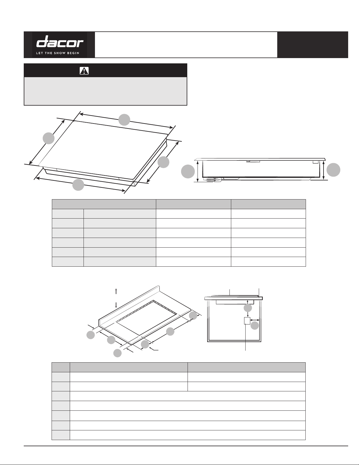
Cabinet 30” (mm) 36” (mm)
A Frame Depth 21
B Frame Width 30” (762) 36” (914)
C Case Depth 19
D Case Width 28
E Conduit Case Height 4” (101) 4” (101)
F Case Height 3
1
1
IMPORTANT:
If installing a range hood or microwave hood combination
above the cooktop, follow the range hood or microwave
hood combination installation instructions for dimensions
and clearance above the cooktop surface.
E
1
/4” (540) 211/4” (540)
/2” (494.6) 19” (481.6)
3
/8” (720) 333/4” (856.6)
/8” (80.5) 31/8” (80.5)
F
Countertop
G
F
Junction box
C
Rear Wall
B
D
A
E
Minimum distance to
combustible side wall above
countertop (both sides)
Cooktop
E
DTI30M***** (30”) DTI36M***** (36”)
A
B
281/
199/
16” - 19
C
D Min 1
E
Min 1” (26 mm). Distance nearest left -/right -side combustible surface above cooktop.
11
2” - 28
/16” (724 mm - 728 mm)
5
/8” (497.4 mm - 499.4 mm)
337/8” - 34” (860 mm - 864 mm)
3
191/
8” - 19
/ 16” (485.6 mm - 487.6 mm)
Min 11/8” (28 mm). Between cutout and the wall behind the cooktop
1
/2” (38 mm). From front edge of cutout and front edge of countertop
F Junction box or outlet 10” (254 mm) maximum from right-hand side of cabinet
G Junction box or outlet 15” (381 mm) minimum from bottom of countertop
Page 2
All specications subject to change without notice. www.dacor.com Ph. 800.793.0093
PLANNING
GUIDE
DTIxx
Modernist
®
30”, 36” Wide,
All tolerances: ±¹/₁₆” (±1.6 mm), unless otherwise stated.
Page 2 of 3
Electric Induction Cooktops
Single Oven Under counter
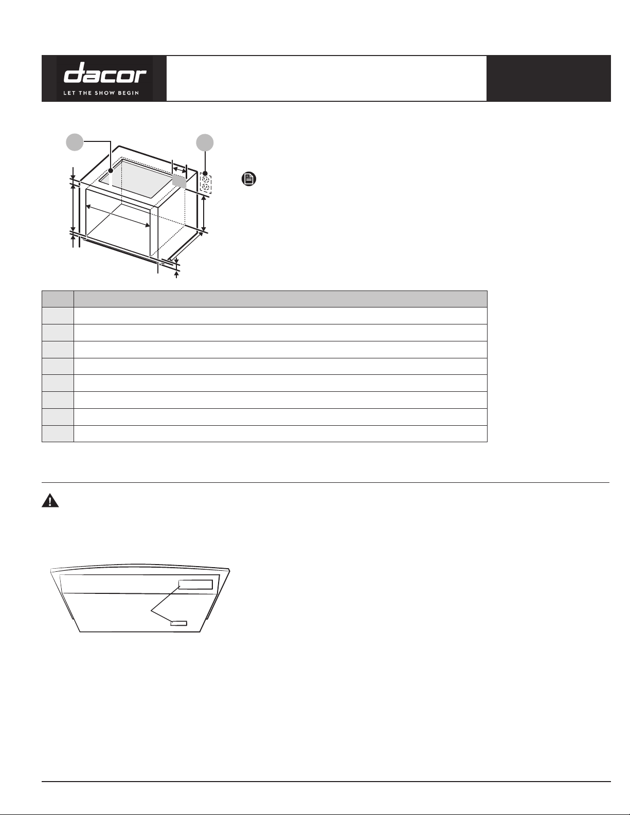
01
A
E
C
D
A Min. 3
B 4” (10.1 cm)
C Min. 28
D Min. 1” / Max. 1
E
F 24” (61 cm)
G Min. 22” (Min 55.9 cm)
H Max. 9
Min. 271/4” / Max. 273/8” (Min. 69.2 cm / Max. 69.5 cm)
02
H
G
F
B
1
/2” / Max. 285/8” (Min. 72.4 cm / Max. 72.7 cm)
01 See built-in oven installation for full instructions. See
label on approved built-in oven models.
02 Refer installation Manual of OVEN.
NOTE
If cabinet has a drawer, a min. 127 mm (5”) clearance from cooktop bottom to
top of drawer (or other surface) in base cabinet is required.
IMPORTANT:
The junction box must be located where it will allow considerable slack in
the conduit for serviceability.
Size
3
/4” (9.5 cm)
1
/4” (Min. 2.5 cm / Max. 3.2 cm)
1
/2” (Max. 24.1 cm) – Junction Box
Electrical requirements
WARNING
Electrical Shock Hazard Disconnect power
before servicing. Use 8 gauge solid
copper wire. Electrically ground cooktop.
Label
This cooktop must be connected to a grounded metal, permanent wiring system. Be sure that the electrical
connection and wire size are adequate and in conformance with the National Electrical Code, ANSI/NFPA 70-latest
edition or CSA Standards C22. 1-94, Canadian Electrical Code, Part 1 and C22.2 No. O-M91-latest edition, and all
local c
odes and ordinances. A copy of the above code standards can be obtained from:
National Fire Protection Association
1 Batterymarch Park
Quincy, MA 02169-7471
Failure to follow these instructions can result in death, fire, or
electrical shock.
If codes permit and a separate ground wire is used, it is
recommended that a qualified electrical installer determine that the
ground path and the wire gauge are in accordance with local codes.
Check with a qualified electrical installer if you are not sure the
cooktop is properly grounded.
Refer the label on the bottom or front of the cooktop for power
requirements and model information.
CSA International
178 Rexdale Boulevard,
Toronto, ON, Canada M9W 1R3
Page 3

All specications subject to change without notice. www.dacor.com Ph. 800.793.0093
PLANNING
GUIDE
DTIxx
Modernist
®
30”, 36” Wide,
All tolerances: ±¹/₁₆” (±1.6 mm), unless otherwise stated.
Page 3 of 3
Electric Induction Cooktops
Before you make the electrical con
To properly install your cooktop, you must determine the type of electrical connection you will be using and follow
the instructions provided for it here.
• A 3-wire or 4-wire, single phase, 208 or 240 volt AC, 60-Hz, pow
pole circuit breaker of at least 40 amps for the 30” cooktop, and of at least 45 amps for the 36” cooktop.
• NOTE
• The cooktop is rated 240 volt. Some models have a neutral (white) wire.
• The cooktop should be connected directly to the junction box through flexible, armored or nonmetallic sheathed,
copper cable. The flexible, armored cable extending from the fuse box or circuit breaker box should be
connected directly to the junction box.
• Locate the junction box to allow as much slack as possible between the junction box and the cooktop so that the
cooktop can be moved if servicing becomes necessarry in the future.
• Do not cut the conduit. Use the length of conduit provided.
• A UL listed or CSA approved conduit connector is necessary at each end of the power supply cable (at the
cooktop and at the junction box). A listed conduit connector is already provided at the cooktop.
• If the house has aluminum wiring, follow the procedure below:
1. Connect a section of solid copper wire to the pigtail leads.
2. Connect the aluminum wiring to the added section of copper wire using special connectors and/or tools
designed and UL listed for joining copper to aluminum.
nection:
er supply is required on a dedicated double
Follow the electrical connector manufacturer’s recommended procedure. Aluminum/copper connection must
conform with local codes and industry accepted wiring practices.
 Loading...