

Page 1
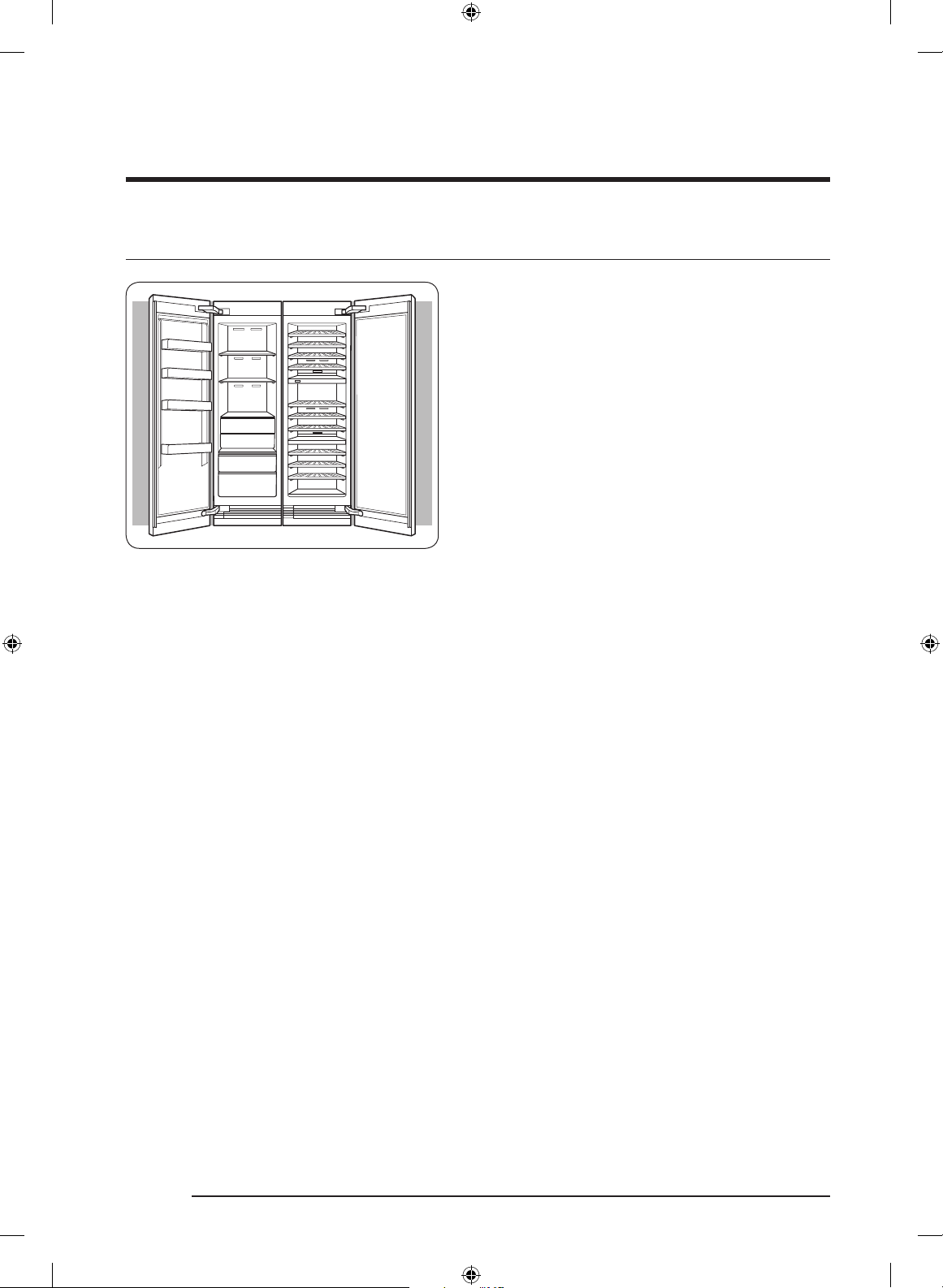
Built-In Wine Cellar
DRW24980RAP/LAP
Installation Instructions
Dacor_BRW9000R_IM_DA68-03621J-02_EN.indd 1 2020-10-19 10:52:56
Page 2
Contents
Before You Begin 4
Important 4
Customer-Service Information 5
If You Need Help 5
Important Safety Instructions 6
State of California Proposition 65 Warning (US only) 6
General Safety Precautions 7
Safety and Warning Information 11
Installation Safety 11
Installation Specifications 13
Installation Options 14
Product Specifications 16
Custom Panel Specifications 17
Handle Specifications 18
Installation 20
Installation Requirements 21
Installation Preparation 21
Grounding the Wine Cellar 24
Cabinet Special Requirements 25
English2
Dacor_BRW9000R_IM_DA68-03621J-02_EN.indd 2 2020-10-19 10:52:56
Page 3

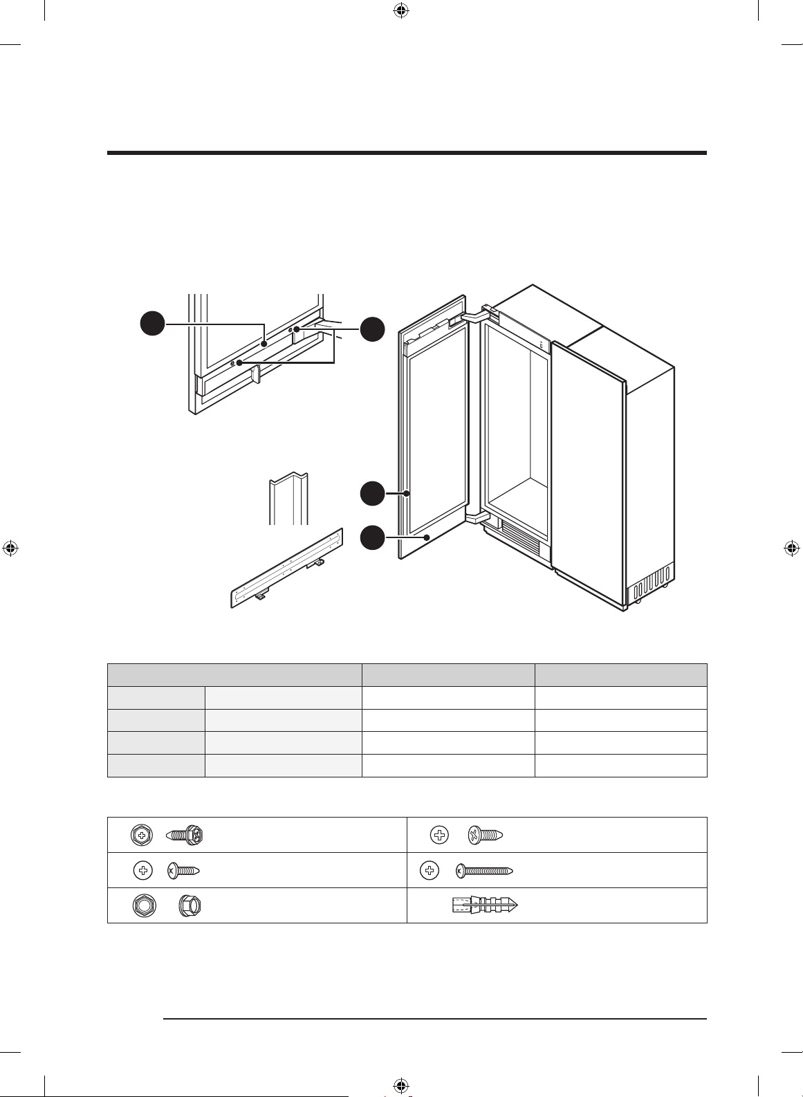
Installation Instructions 26
1. Uncrating the Wine Cellar 26
2. Moving the Wine Cellar 27
3. Installation Preparation 28
4. Attaching the Anti-tip-Bracket 28
5. Removing Upper Door Cover, Kickplate 31
6. Attaching Insulators on the Side of the Wine Cellar
- Single Installation 34
7. Attaching insulators on the side of the freezer or fridge or Wine Cellar
- Side-by-side (Pair) Installation 35
8. Connecting the Two Chassis 38
9. Adjusting the door Opening Angle 39
10. Moving the Wine Cellar Into Its Enclosure 40
11. Removing Two Levers 42
12. Leveling the Wine Cellar 43
13. Attaching Two Levers 45
14. Attaching the Wine Cellar’s Top Cover 46
15. Securing the Wine Cellar 47
16. Attaching the Custom-Door-Panel Brackets 48
17. Hanging a Custom Panel 50
18. Preparing the Panel for Adjustment 51
19. Aligning the Panel 52
20. Attaching the Door’s Interior Covers 56
21. Attaching Grill, Kickplate and Toe Kickplate (optional) 59
22. Attaching the Wine Cellar Trim 61
23. Attaching Trim Top Cover 62
24. Assembling the Wine Rack 63
25. Disassembling the Wine Rack 66
26. Adjusting the Door Spring 67
27. Cleaning 67
28. Installation Checklist 68
English 3
Dacor_BRW9000R_IM_DA68-03621J-02_EN.indd 3 2020-10-19 10:52:56
Page 4
SAVE THESE INSTRUCTIONS
Before You Begin
Important
• The overall design and/or accessories
may differ with the model.
Installer
• To promote safety and minimize
problems, read this manual thoroughly
before starting the installation. Leave
this manual with the user.
• Write the appliance’s model/serial
numbers in this manual for service/
maintenance reference.
• Model/serial numbers are on the data
label in the Wine Cellar compartment.
User
• Keep this manual for personal reference
and for that of inspectors, service
personnel, etc.
English4
Dacor_BRW9000R_IM_DA68-03621J-02_EN.indd 4 2020-10-19 10:52:56
Page 5

SAVE THESE INSTRUCTIONS
Customer-Service Information
If You Need Help
If you have questions or problems with installation, contact your Dacor® dealer or the
Dacor Customer Assurance Team. If your Dacor appliance is under warranty, call Dacor
Distinctive Service. Have the appliance’s model/serial numbers available when you call.
(These numbers are on the data label on the right-hand door jamb inside the refrigerator.)
Dacor Customer Assurance
Phone: 833-35-ELITE (833-353-5483) USA, Canada
Mon – Fri 5:00 a.m. to 5:00 p.m. Pacific Time
Website: www.dacor.com/customer-care/contact-us
insert here: Product Information: knowledgebase.dacor.com
All specifications are subject to change without notice. Dacor assumes no liability for
changes to specifications.
© 2017 Dacor, all rights reserved.
English 5
Dacor_BRW9000R_IM_DA68-03621J-02_EN.indd 5 2020-10-19 10:52:56
Page 6
SAVE THESE INSTRUCTIONS
Important Safety Instructions
The Important safety instructions and warnings in these instructions are not meant to
cover all possible problems and conditions that can occur.
Use common sense and caution when installing, maintaining, or operating this or any
other appliance.
Always contact the Dacor Customer Assurance Team about problems and conditions that
you don’t understand. See Customer-Service Information.
Safety symbols and labels
These alerts are meant to bring attention to important areas in the manual.
Whenever you see these symbols or labels, read the message carefully before continuing.
DANGER
Immediate hazards that WILL cause severe personal injury or death.
WARNING
Hazards or unsafe practices that MAY cause in severe personal injury or death.
CAUTION
Hazards or unsafe practices that MAY cause in minor personal injury or property damage.
State of California Proposition 65 Warning (US only)
WARNING : This product contains chemicals known to the State of California to cause
cancer and birth defects or other reproductive harm.
English6
Dacor_BRW9000R_IM_DA68-03621J-02_EN.indd 6 2020-10-19 10:52:56
Page 7
SAVE THESE INSTRUCTIONS
WARNING - R600a Refrigerant
This appliance contains isobutane refrigerant, R600a, a natural gas with high
environmental compatibility; however, it is also flammable. Please adhere to the warnings
below
• When handling, installing and operating the appliance, care should be taken to avoid
damage to the refrigerant tubing.
• Servicing shall be performed by manufacture-authorized service personnel and
component parts shall be replaced with manufacturer-authorized replacement
components.
• Refrigeration products contain refrigerants, which under federal law must be removed
prior to product disposal.
• Keep ventilation openings in the appliance enclosures or in the built-in structure clear
of obstruction.
• In order to avoid the creation of a flammable gas-air mixture if a leak in the
refrigerating circuit occurs, the size of the room in which the appliance may be sited
depends on the amount of refrigerant used. The room must be 35.3 ft³ in size for every
8 g of R-600a refrigerant inside the appliance.
• The installation location should not be exposed to direct sunlight and avoid placing
near any electric appliances or heat source, e.g. stove, cooktop, oven, or radiator, etc.
• If you use two products side by side, for safety reason, be sure to use certified
products in explosive gas atmospheres.
• Do not use mechanical devices or other means to accelerate the defrosting process.
• Do not damage the refrigerant circuit.
• Do not use electrical appliances inside the food storage compartment of the appliance.
General Safety Precautions
DANGER
IMPORTANT:
To prevent child entrapment and suffocation when discarding an old appliance:
• Take off the door(s).
• Leave the racks in place so children cannot easily climb inside.
• Cut the prongs off the power plug and discard them.
• Cut the power cable off and discard it separately from the old appliance.
English 7
Dacor_BRW9000R_IM_DA68-03621J-02_EN.indd 7 2020-10-19 10:52:56
Page 8
SAVE THESE INSTRUCTIONS
Important Safety Instructions
To avoid the possibility of explosion or fire, do not store or use combustible, flammable
or explosive vapors and liquids (such as gasoline) inside or in the vicinity of this or any
other appliance. Also keep items that could explode, such as aerosol cans away from
cooktop burners, ovens and range hoods. Do not store flammable or explosive materials in
adjacent cabinets or areas.
WARNING
IMPORTANT: This appliance is equipped with a three-prong grounding electric plug for
protection against possible electric shock hazards. It must be plugged into a dedicated,
grounded, electrical outlet. If only a two-prong electrical outlet is available, it is the
responsibility of the customer to have it replaced with a dedicated, properly grounded
three-prong electrical outlet.
• Do not kink or pinch the power supply cord of the appliance.
• Never unplug the appliance by pulling on the power cord.
• Always grip the plug firmly and pull straight out from the electrical outlet.
• Disconnect this appliance when not in use.
• Do not install, repair, modify, or replace any part of the appliance unless specifically
recommended in the literature accompanying it.
• A qualified service technician should perform all other services.
DO NOT cut or remove the third (ground)
prong from the power cord.
DO NOT use an adapter plug.
DO NOT use a power cord that is frayed or
damaged.
DO NOT connect the appliance to an
extension cord. Keep the power cord away
from heated surfaces.
NOTE
• Use of an electrical outlet with a
ground.
• Use of an electrical outlet with a
ground fault interrupter (GFI) is not
recommended.
English8
Dacor_BRW9000R_IM_DA68-03621J-02_EN.indd 8 2020-10-19 10:52:56
Page 9

SAVE THESE INSTRUCTIONS
WARNING
• To reduce the risk of fire, electric shock, serious injury or death when using your
appliance, follow basic safety precautions, including the following:
• If you receive a damaged product, immediately contact your dealer or builder. Do not
install or use a damaged appliance.
• Make sure that this appliance has been properly installed according to these
installation instructions.
• Make sure to install in outlet locations according to electric supply location.
• Refrigeration equipment and refrigerants must be properly disposed of in a
professional and appropriate way, in accordance with the current local regulations
and laws which protect the environment. This applies to your old appliance and to
your new unit once it has reached the end of its service life. DO NOT dispose of the
appliance in a landfill or with urban waste. Contact local waste disposal centers for
information on how to dispose of recyclable waste.
• Take care when handling, moving, using or disposing of the appliance to avoid
damaging the refrigeration system.
• Do not install or use outdoors or in wet conditions. This appliance is not designed for
installation in a recreational vehicle or boat.
• Keep packaging materials away from children. Plastic sheets and bags can cause
suffocation.
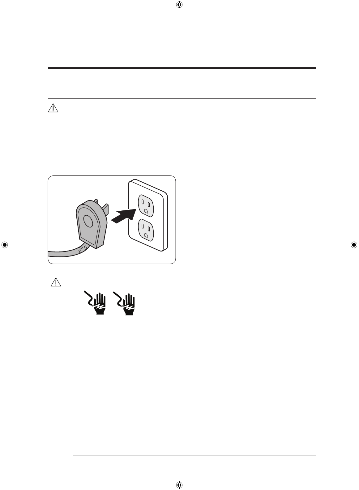
• Connect this appliance to a 115 V, 15 A. circuit that is controlled by a circuit breaker or
fuse. This appliance should have its own separate grounded circuit.
• Do not kink or pinch the power supply cord of the appliance. Never unplug the
appliance by pulling on the power cord. Always grip the plug firmly and pull straight
out from the electrical outlet.
• Disconnect this appliance when not in use.
• Do not install, repair, modify, or replace any part of the appliance unless specifically
recommended in the literature accompanying it. A qualified service technician should
perform all other services.
• Before performing any type of service, switch power off at the circuit breaker panel.
• This appliance is not intended for use by persons (including children) with reduced
physical, sensory abilities, or lack of experience and knowledge, unless they are
properly supervised by a person responsible for their safety. Children must be
supervised for their safety.
• Never allow anyone, including children to sit, stand or climb on any part of the
appliance, including the door. Doing so may cause damage, serious injury or death.
English 9
Dacor_BRW9000R_IM_DA68-03621J-02_EN.indd 9 2020-10-19 10:52:57
Page 10

SAVE THESE INSTRUCTIONS
Important Safety Instructions
• If the power cord is damaged, it must be replaced by the manufacturer or a qualified
service technician in order to avoid a safety hazard. Do not tamper with the controls.
• Clean this appliance regularly as instructed in the Care and Cleaning section of the User
manual. Clean the ice bucket or drawer regularly.
• When the freezer is functioning, do not touch the inner stainless steel surfaces with
wet or damp hands, since skin may stick to the very cold surfaces.
• Do not use any type of electrical equipment inside the wine cellar compartments.
• Do not obstruct any of the vents or openings on the appliance.
• To avoid risk of the appliance tipping over it is mandatory to secure the appliance to
the wall by means of the two supplied anti-tip brackets.
• Use this appliance only for its intended purpose: the storage of food and beverages. It
is not intended for commercial or industrial use.
• Be careful when installing electrical component box is damaged or not by the shock
departure.
• Hold the handle when opening and closing the door.
• When you open and close the door, be careful not to put your hands in the doorway.
English10
Dacor_BRW9000R_IM_DA68-03621J-02_EN.indd 10 2020-10-19 10:52:57
Page 11
Safety and Warning Information
Installation Safety
WARNING
• Before installing the wine cellar, connect it to a power outlet and turn the wine cellar
ON to make sure the wine cellar is working.
• Choose a location away from a heater, boiler, or direct sunlight.
• Install the unit where air flows freely and where the wine cellar is well ventilated.
• Install the unit so that air flows unobstructed through the front air grill. If the air
circulation is not ensured, it may interfere with the normal functioning of the product.
• Outside animals (rodents) can chew on the power cord and cause a fire; therefore,
install the unit where there is no access to animals.
• If the cabinet is made of soft material (ex: plaster, etc.), it can have a weak structure
and be damaged. Therefore, use a cabinet made of sturdy, strong material.
• Install the wine cellar with a team of at least 2 people.
• Refer to the dimensions of the cabinet and prepare the cabinet with good air
circulation.
• Use cabinet that will not warp from product heat emissions or humidity from the
opening and closing of the wine cellar.
NOTE
This wine cellar is a “built-in” style wine cellar, meaning that the wine cellar requires
installation inside a recess in existing kitchen cabinetry.
Before moving the wine cellar, clear the route to the location where it will be installed.
Check all product dimensions and the tipping radius with any doorways, hallways, stairs,
corners, etc., to ensure a clear passageway.
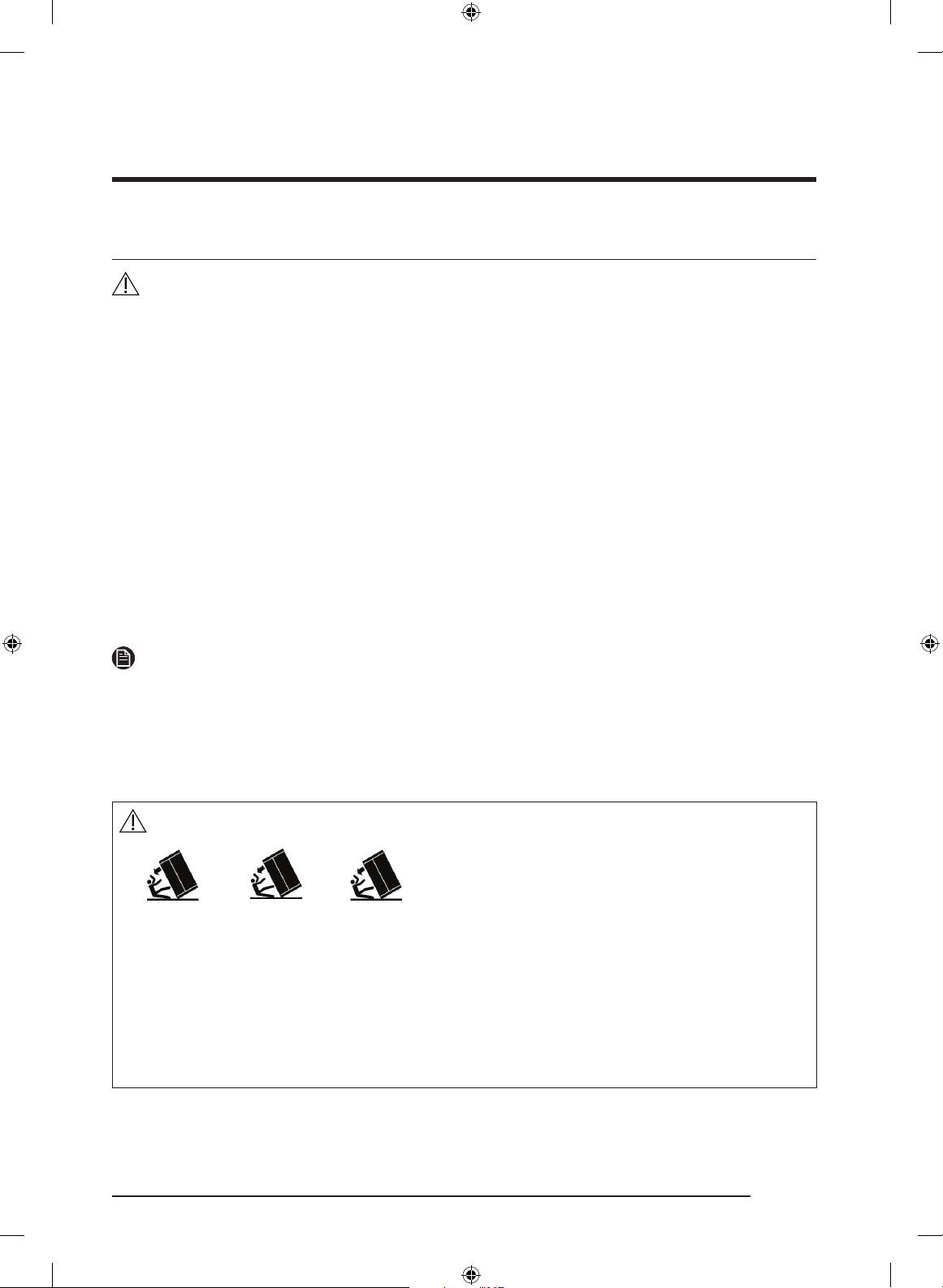
WARNING
Tip Hazard
This appliance is relatively heavy on the top and prone to tip over when not securely
installed.
Keep doors taped closed until wine cellar is in its final position and ready to be secured
in place.
Use two or more people to move and install wine cellar.
Failure to do so can result in death or serious injury.
English 11
Dacor_BRW9000R_IM_DA68-03621J-02_EN.indd 11 2020-10-19 10:52:57
Page 12
Safety and Warning Information
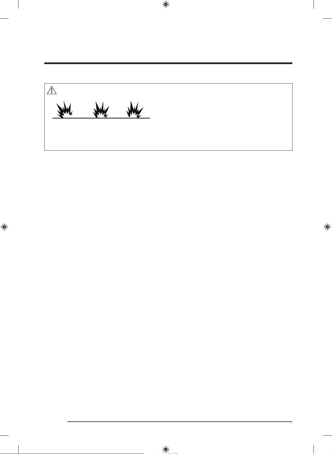
DANGER
Explosion Risk
Keep flammable materials and vapors - such as gasoline - away from the wine cellar.
Failure to do so can result in death, explosion, or fire.
English12
Dacor_BRW9000R_IM_DA68-03621J-02_EN.indd 12 2020-10-19 10:52:57
Page 13
Installation Specifications
WARNING
Observe all governing codes and ordinances during planning and installation. Contact your
local building department for further information.
WARNING
Electrical and grounding connections must comply with the applicable portions of the
national electrical code and/or other local electrical codes.
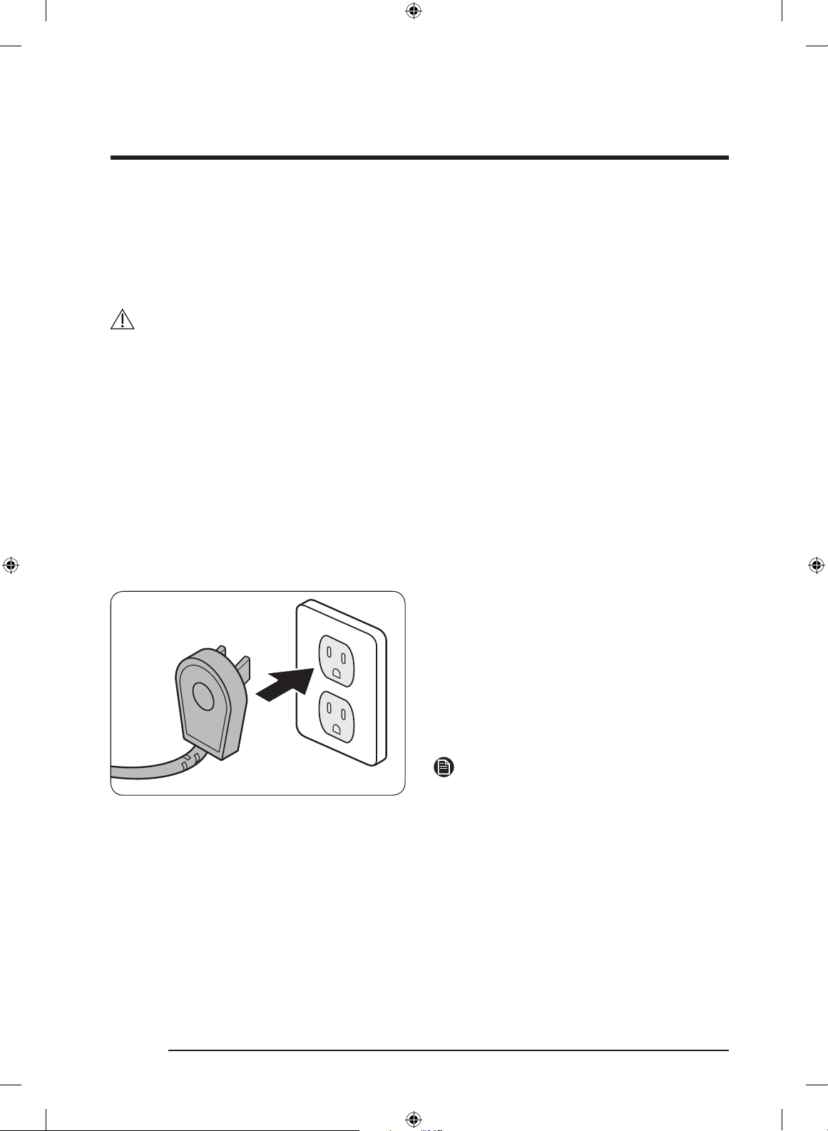
This appliance comes with an electrical cord with a three-prong grounding plug for a
115 Vac, 15 Amp. power supply. Plug it into a 115 Vac, three-prong, grounding electrical
outlet only.
The appliance features a lighting system with high intensity LED lamps. Do not stare into
these lamps when they are on to avoid possible eyesight damage.
English 13
Dacor_BRW9000R_IM_DA68-03621J-02_EN.indd 13 2020-10-19 10:52:57
Page 14
Installation Options
There are many different installation options.
These are limited only by the design of the kitchen.
Individual appliance
OK OK X
Side-by-Side (Pair)
OK X XX
English14
Dacor_BRW9000R_IM_DA68-03621J-02_EN.indd 14 2020-10-19 10:52:57
Page 15
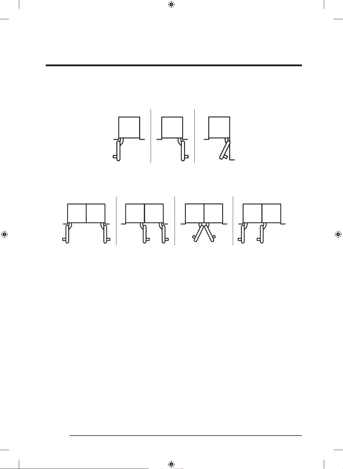
Individual appliances with partition
NOTE
• The minimum thickness of the partition is 1 1/4” (32 mm).
• At 1 1/4” (32 mm), the door swings must open towards as case 1.
• At more than 1 9/16” (40 mm), the door swing can open same direction and door open
angle is 90 degree as case 2.
At more than 7 7/8” (200 mm), the door swing can open toward each other and door open
angle is 90 degree as case 3.
For this installation option it is recommend to install the 90 degree door stop. In order to
minimize the partition thickness.
If a 115 degree door opening angle is desired, Distance of “F” (16 page) for a partition
thickness is recommended.
• Partition thickness is dependent on handle depth. Dimension above is acceptable for
Dacor handles.
1 1/4” (32 mm) 1 9/16” (40 mm)
OK
Case 1 Case 2 Case 3
1 9/16” (40 mm)
All doors swings are recommended to be on
the same side.
OK OK OK
1 9/16” (40 mm) 7 7/8” (200 mm)
1 9/16” (40 mm)
OKOK
The door swing of the individual column must
open the same way as the door swing of the
side-by-side.
English 15
Dacor_BRW9000R_IM_DA68-03621J-02_EN.indd 15 2020-10-19 10:52:58
Page 16
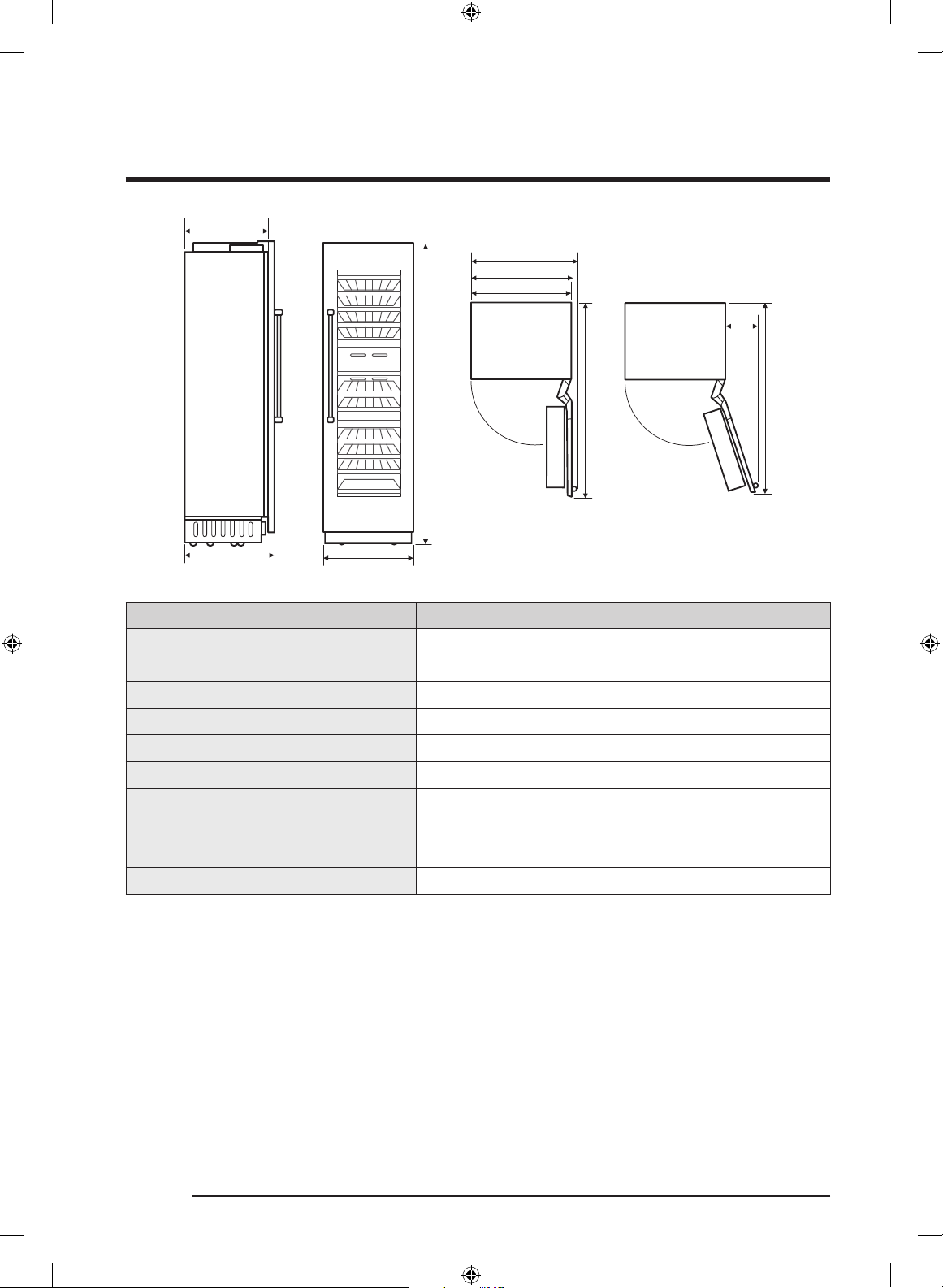
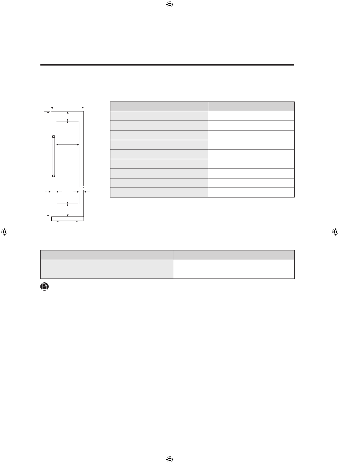
Product Specifications
B1
C
AB
Callout 24”
A 23 3/4” (603 mm)
B (With Panel) 25” (635 mm)
B1 (Without Panel) 23 13/16” (605 mm)
C 83 3/8” (2118 mm)
D 23 5/8” (600 mm)
D1 24 7/8” (631 mm)
D2 27 9/16” (701 mm)
E 50 3/4” (1289 mm)
F 13 11/16” (348 mm)
G 49 11/16” (1261 mm)
90°
D2
D1
D
F
E
115°
G
English16
Dacor_BRW9000R_IM_DA68-03621J-02_EN.indd 16 2020-10-19 10:52:58
Page 17
Custom Panel Specifications
H1
W2 W2
W1
H2
W3
H3
H4
Callout 24”
W1
W2
W3
H1
H2
H3
62 25/32” (1594.5 mm)
H4
Panel Thickness
Max Weight
23 3/4” (603 mm)
3 9/32” (83.5 mm)
17 5/32” (436 mm)
79 7/8” (2029 mm)
7 23/32” (196 mm)
9 3/8” (238.5 mm)
3/4” (19 mm)
55.0 lb (25 kg)
Do not exceed the max load that the custom panel can endure. Before crafting the panel,
check the strength of the panel’s material and the load of attachments to the panel.
24”
Custom Panel
Maximum Weight
55.0 lb (25 kg)
NOTE
• Standard Custom panel thickness is 3/4” (19 mm).
English 17
Dacor_BRW9000R_IM_DA68-03621J-02_EN.indd 17 2020-10-19 10:52:58
Page 18
Product Specifications
Handle Specifications
Handle
Countersunk
screw
Custom
panel
Appliance
door/drawer
Handle Installation for Units with
Custom Door Panels (Top View)
Before installing the custom panels, you
must first install the door/drawer handles.
With custom panel models, you have the
advantage of being able to select a handle
style that meets your own personal taste.
Handles are not provided with custom
panel models. Selected handle kits are
available through your Dacor dealer. Dacor
does not advise the use of single pull
knobs.
The panel craftsman needs to select and
purchase the required fasteners for the
installation. The screw heads must be
countersunk into the panel to prevent
interference during depth adjustment.
CAUTION
We recommend installing a handle for a custom panel. Without the handle, you may catch
your fingers in the door when opening or closing the door.
English18
Dacor_BRW9000R_IM_DA68-03621J-02_EN.indd 18 2020-10-19 10:52:58
Page 19
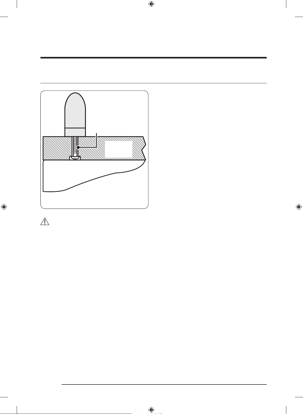
Attach the Dacor Handle
WARNING
Follow these instructions to attach the Dacor handle. Otherwise, the handle may be
damaged or malfunction.
1. Put the reinforced handle support on the rear of the door panel, and then put the
handle on the front of the door panel.
2. As shown, tighten the 4 screws on each of the upper and the lower sides of the handle.
Do not tighten them excessively.
Panel
(PW) M4x16
4 ea
Reinf Handle
Handle
English 19
Dacor_BRW9000R_IM_DA68-03621J-02_EN.indd 19 2020-10-19 10:52:58
Page 20

Installation
WARNING
Do not install the appliance:
• outdoors,
• in an environment with dripping water.
Appliance is very heavy :
Wine Cellar 24” approx. 397 lb / 180 kg
Installation room
The appliance should be installed in a dry, ventilated room.
Secure installation
The appliance is very heavy and has a tendency to tilt forwards when the appliance door
is opened.
Do not open the door until there is no possibility of the appliance tipping over.
The most secure way to install the appliance is to use the supplied anti-tipping devices.
Floor
The subsurface must be level and even in order to ensure that the appliance is securely
installed and works correctly.
The subsurface must be made from a hard, non-flexible material to cover the weight of
appliance.
Aligning the appliance
To ensure that the appliance functions correctly, it must be levelled properly.
Glass door
When moving or installing the appliance, be careful not to damage the glass door.
English20
Dacor_BRW9000R_IM_DA68-03621J-02_EN.indd 20 2020-10-19 10:52:58
Page 21
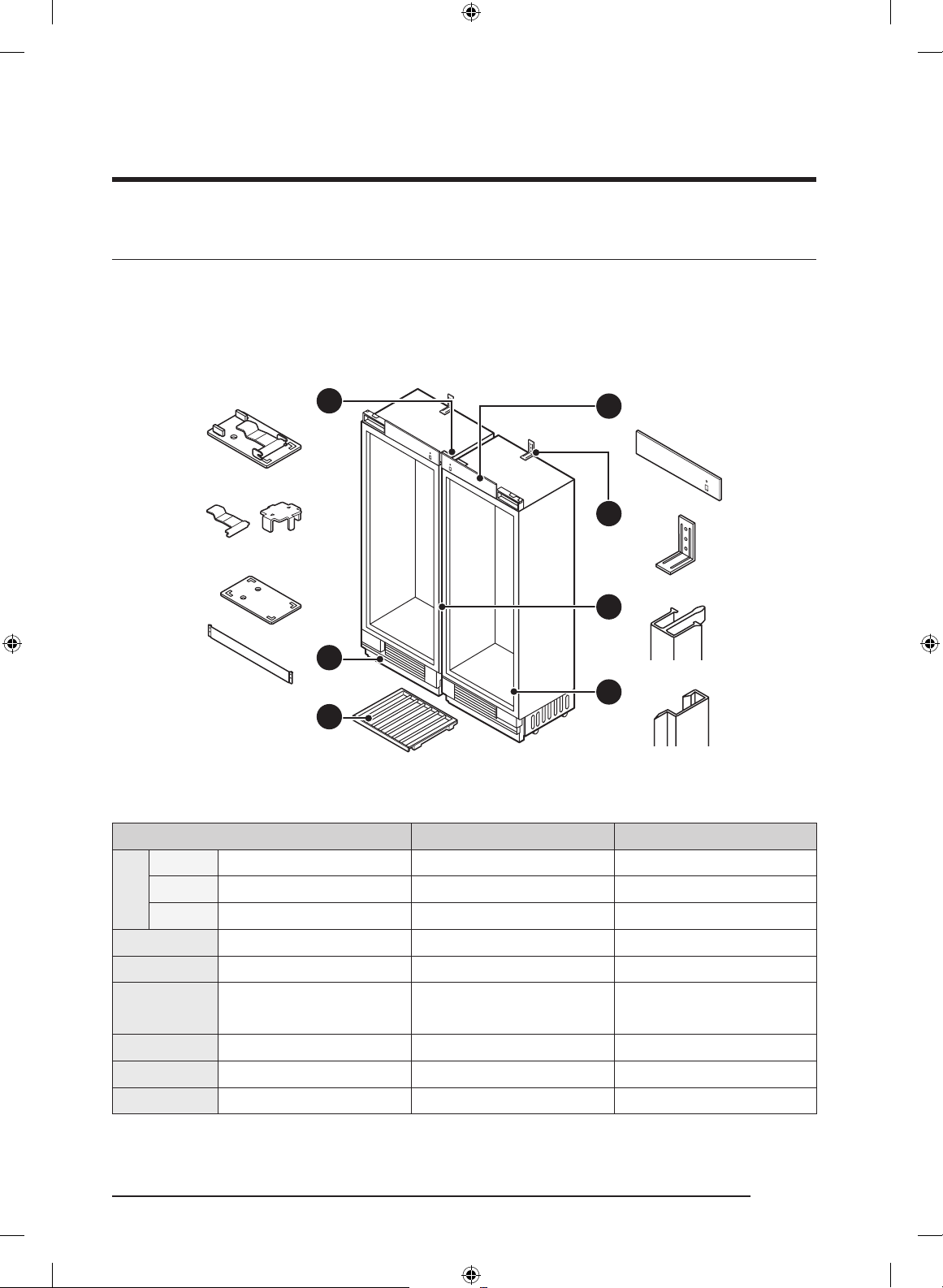
Installation Requirements
Installation Preparation
Cabinet installation parts
Using the table on next page, verify that all installation parts are present as you unpack
the appliance.
A
A1
Check the installation parts when unpacking.
A1 LEVER - 2
A
A2-1 LOWER BRACKET - 1
A2-2 UPPER BRACKET - 1
B KICKPLATE 1 2
C Refrigerator Top Cover 1 2
D ANTI-TIP BRACKET
E CENTER TRIM - 1
F CABINET SIDE TRIM 2 2
G Wine Rack 10 20
A2-1
A2-2
B
G
PARTS SINGLE-INSTALLATION PAIR-INSTALLATION
18”, 24”, 30” : 1
36” : 2
C
D
E
F
18”, 24”, 30” : 2
36” : 4
English 21
Dacor_BRW9000R_IM_DA68-03621J-02_EN.indd 21 2020-10-19 10:52:59
Page 22
Installation Requirements
Door installation parts
Using the table below, verify that all door-installation parts are present as you unpack the
appliance.
A'
B'
C'
D'
Check the installation parts when unpacking.
PARTS SINGLE-INSTALLATION PAIR-INSTALLATION
A’ LOWER DOOR CAP 1 2
B’ CAP 2 4
C’ DOOR SIDE TRIM 2 4
D’ PANEL BRACKET 2 4
Screw and Nut
M6x12 12 ea (FH) M4x14 22 ea
(TH) M4x16 24 ea M4x35 3 ea
M13 2 ea Ø6x30 3 ea
English22
Dacor_BRW9000R_IM_DA68-03621J-02_EN.indd 22 2020-10-19 10:52:59
Page 23
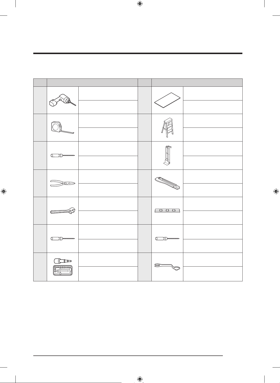
Tools required
No. Tool No. Tool
Electric Screwdriver
1
8
Measuring Tape
2
9
Flat/Slot Head
3
Screwdriver
10
Cutter (Scissors)
4
11
Adjustable Wrench
5
12
Phillips Head
6
Screwdriver
13
Protective Floor Mat
Stepladder
Appliance Dolly
Cutter
Level
Star Head Screwdriver
Ratchet
7
3/8” (10 mm),
14
1/2” (13 mm)
Dacor_BRW9000R_IM_DA68-03621J-02_EN.indd 23 2020-10-19 10:53:02
Combination Wrench
3/8” (10 mm),
1/2” (13 mm)
English 23
Page 24
Installation Requirements
Grounding the Wine Cellar
CAUTION
Electrical and grounding connections must comply with the applicable portions of the
national electrical code and/or other local electrical codes.
This appliance comes with an electrical cord with a three-prong grounding plug for a
115 Vac, 15 Amp. power supply. Plug it into a 115 Vac, three-prong, grounding electrical
outlet only.
DO NOT, UNDER ANY CIRCUMSTANCES,
CUT OR REMOVE THE THIRD (GROUND)
PRONG FROM THE POWER CORD.
DO NOT USE AN ADAPTER PLUG TO
CONNECT THE WINE CELLAR TO A
2-PRONG OUTLET.
DO NOT USE AN EXTENSION CORD WITH
THIS APPLIANCE.
WARNING
Electric Shock Hazard
Plug into a grounded, dedicated 3-prong outlet.
Do not remove the ground prong.
Do not use an adapter.
Do not use an extension cord.
Failure to follow these instructions can result in death, fire, or electric shock.
English24
Dacor_BRW9000R_IM_DA68-03621J-02_EN.indd 24 2020-10-19 10:53:02
Page 25
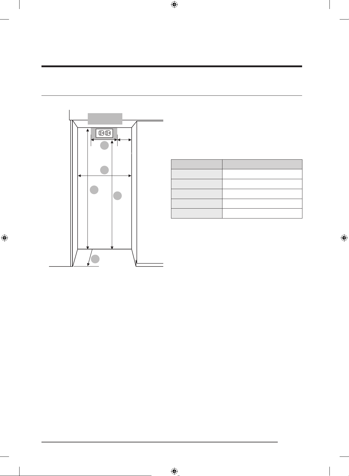
Cabinet Special Requirements
Electric supply
location
D
5”
(127)
A : Cabinet Width
B : Cabinet Depth
C : Cabinet Height
D : Electrical supply width location
E : Electrical supply height location
A
A 24” (610 mm)
B 25” (635 mm)
Callout 24”
C
E
C 84” (2134 mm)
D 14” (356 mm)
E 80” (2032 mm)
B
• B : Includes the standard door panel thickness with 3/4”.
• Installation inside a cabinet of this width allows the wine cellar trim to be attached
directly to the surrounding cabinets.
English 25
Dacor_BRW9000R_IM_DA68-03621J-02_EN.indd 25 2020-10-19 10:53:02
Page 26
Installation Instructions
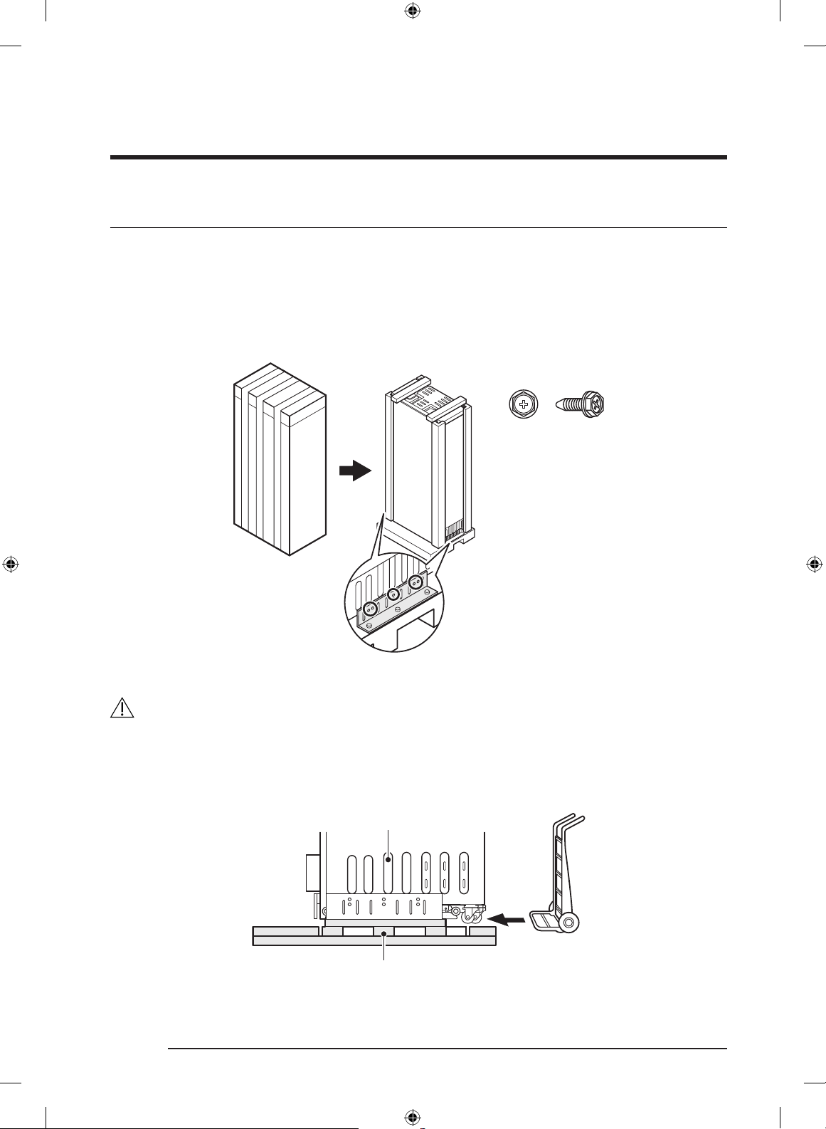
1. Uncrating the Wine Cellar
Check the appliance for transit damage.
Do not install the appliance if it is visibly damaged.
If in doubt, contact your dealer.
1. Remove the PP-banding, cardboard crate, EPS, and Pe-bag.
2. Remove the brackets from the pallet by unscrewing the bolts (five per bracket).
10 eaM6x10
Unscrew the bolts
CAUTION
Use caution not to damage the appliance when unloading it from the pallet.
3. As shown, insert the hand truck between the appliance and the wooden packing. While
tilting the appliance up to the rear, unload it from the wooden packing.
Appliance Bottom
Wooden Packing
English26
Dacor_BRW9000R_IM_DA68-03621J-02_EN.indd 26 2020-10-19 10:53:03
Page 27
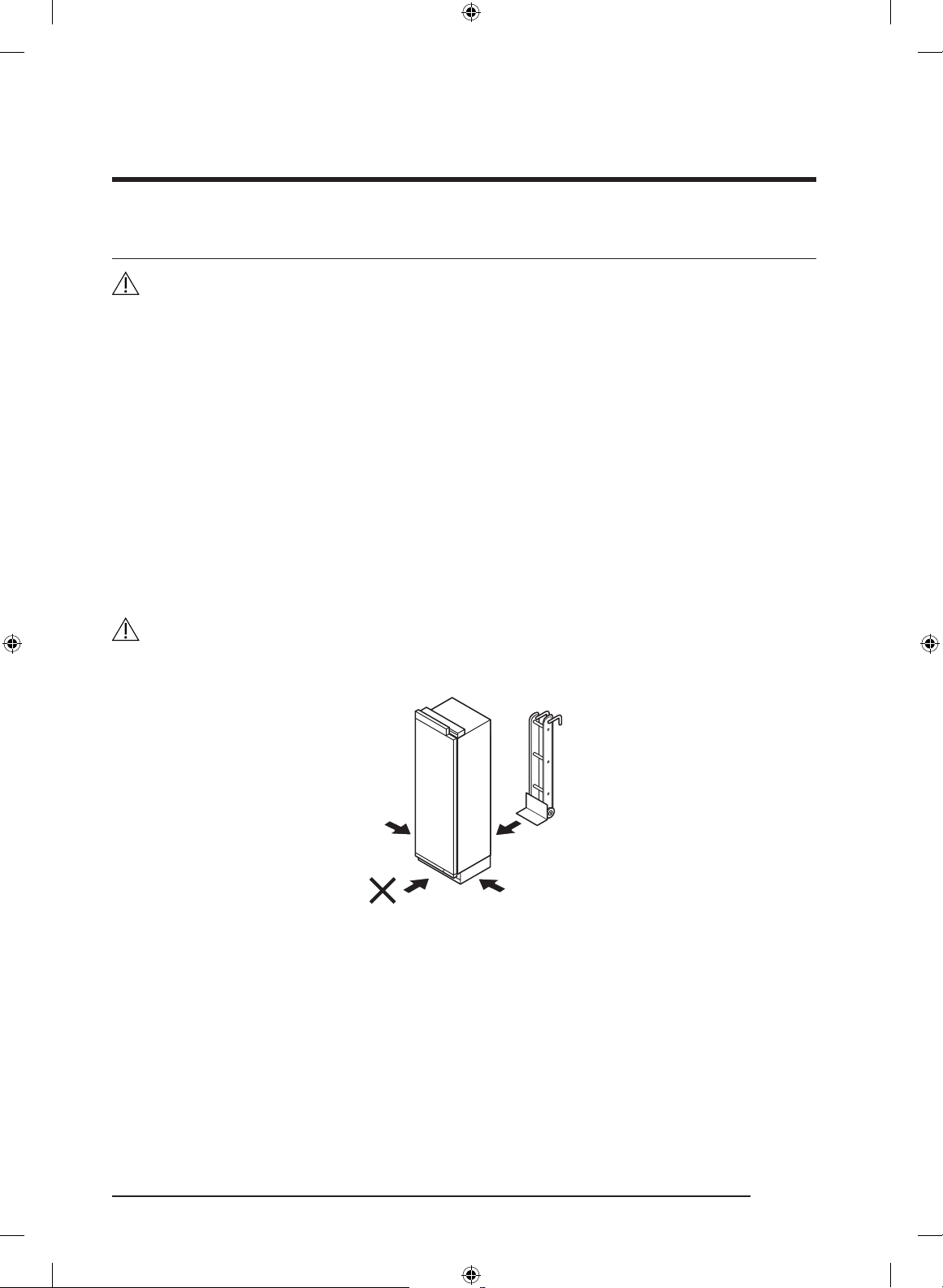
2. Moving the Wine Cellar
WARNING
The appliance is very heavy. When moving the refrigerator, all personnel must take care
not to injure themselves or the appliance.
1. Secure the refrigerator to a suitable means of transport (preferably an appliance dolly),
and move the refrigerator near its installation cabinet.
2. Move and install with a minimum of two persons.
3. Be very careful to avoid floor damage. Delicate flooring should be protected with
plywood, hard cardboard, or similar material.
4. Before moving the refrigerator, verify that it will fit through all door openings,
stairwells, and overhead obstructions.
• TIPPING HAZARD: The refrigerator is large, heavy, and tips easily when not secured.
Always move the refrigerator in an upright position if possible. If not, move the
refrigerator on its back. Secure the doors shut during transport.
WARNING
Be careful that electrical component box is not damaged when installing.
OK (Recommended)
OK
OK
English 27
Dacor_BRW9000R_IM_DA68-03621J-02_EN.indd 27 2020-10-19 10:53:03
Page 28
Installation Instructions
3. Installation Preparation
Unpack installation materials and accessories.
See the Installation preparation section on Installation Requirement chapter.
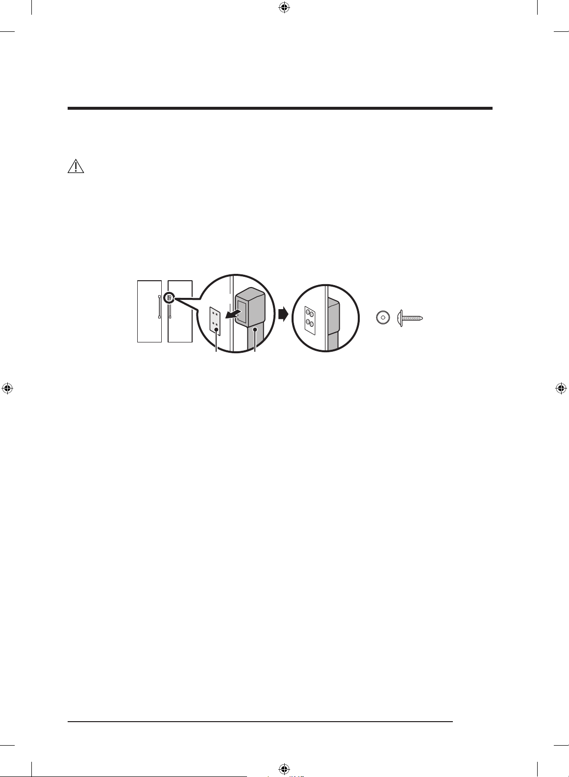
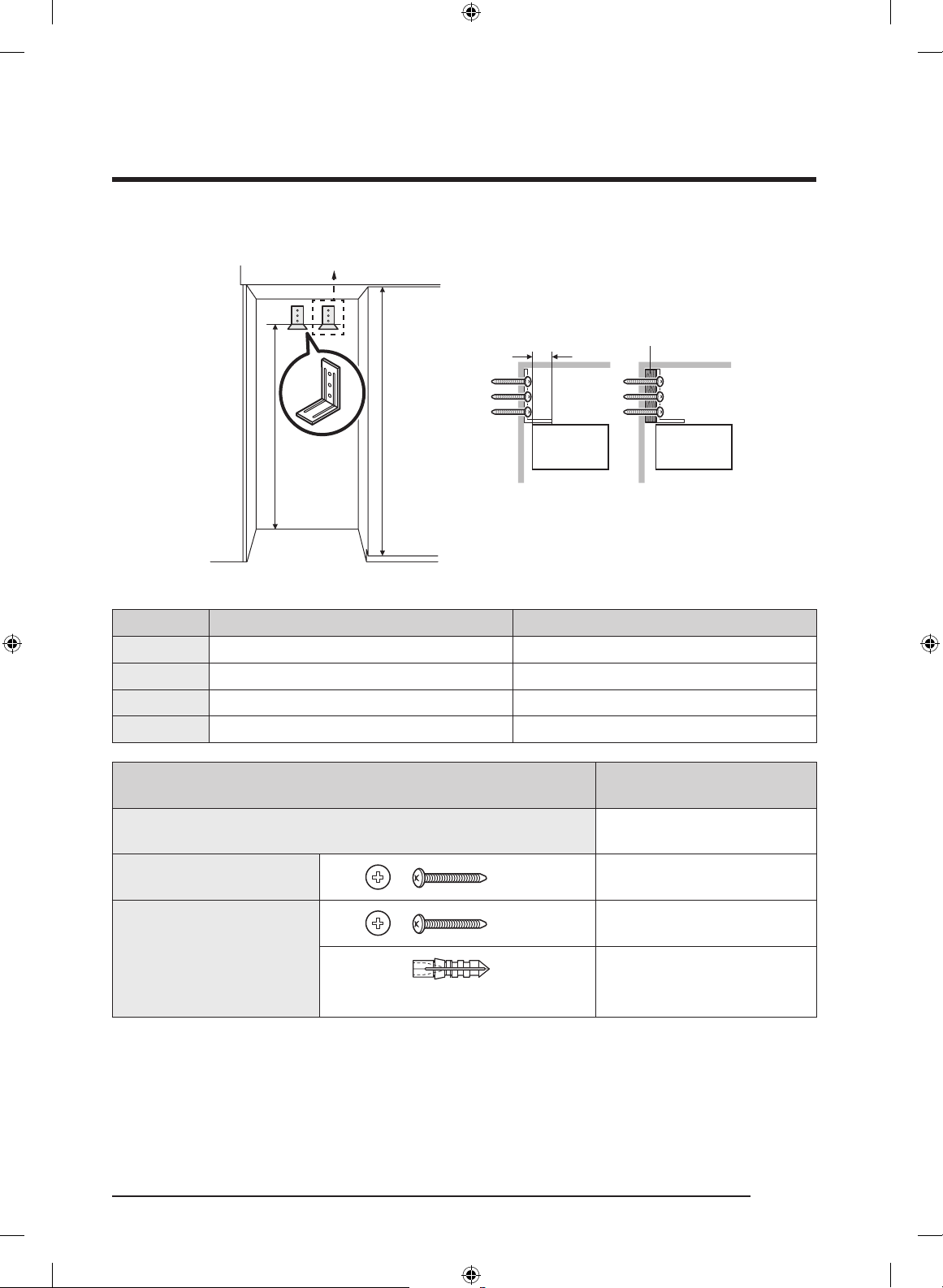
4. Attaching the Anti-tip-Bracket
WARNING
To keep the unit from tipping forward, an anti-tip bracket must be installed. Before
attaching the bracket, ensure that no electrical wiring or plumbing is in the area where the
screws will penetrate. One such bracket per appliance is required.
CAUTION
Always wear safety glasses and other necessary protective devices or apparel when
installing or working with anchors.
Dacor does not recommend that you anchor the anti-tip bracket in light-weight masonry
(e.g., block, brick) or in new, uncured concrete.
Make sure the wall or the cabinet that the brackets are studded in has enough strength to
withstand the safety load.
Wooden Wall
M4x35
Concrete Wall
M4x35
ø6x30
The anti-tip brackets must extend at least 2” (50 mm) over the appliance to secure the
appliance. If this minimum length cannot be observed for structural conditions it is
possible to do this by fastening a spacer (wood) behind the anti-tip angle.
1. Bracket height is measured from the
floor and depends on the cabinet
height.
NOTE
Bracket height
= Cabinet height – 4 3/32” (104 mm)
2. Attach the anti-tip brackets. Ensure the
screws hold the bracket tightly.
English28
Dacor_BRW9000R_IM_DA68-03621J-02_EN.indd 28 2020-10-19 10:53:04
Page 29
For 36” models, use 2 anti-tip brackets.
2” (50)
A
Cabinet Height
Appliance
Spacer (wood)
Appliance
Option Cabinet height A
1 83 1/2” (2121 mm) 79 13/32” (2017 mm)
2 83 3/4” (2127 mm) 79 5/8” (2023 mm)
3 84” (2134 mm) 79 7/8” (2030 mm)
4 84 1/4” (2140 mm) 80 1/8” (2036 mm)
24”
ANTI-TIP BRACKET 1 ea
wooden wall M4x35 3 ea
M4x35 3 ea
concrete wall
ø6x30
3 ea
(HOLDER LOCK)
• 3 screws/holder locks per bracket.
English 29
Dacor_BRW9000R_IM_DA68-03621J-02_EN.indd 29 2020-10-19 10:53:04
Page 30
Installation Instructions
Anti-tip bracket considerations
1. Bracket positioning: follow the cabinet-
Wall
Anti-Tip-Bracket
Product
2. Screws: Tighten all 3 screws on the
3. Push the product up against the rear
4. Spacer: If using the spacer, you must
• The height of the spacer must be
• The spacer must be fixed separately
specific height table.
brackets.
wall of the cabinet.
follow the positioning specifications of
the bracket (see the table above).
CAUTION
calculated based on the depth of the
cabinet.
from the cabinet.
When installing the product into the cabinet
Tape or Fixer
Before positioning the product in the
cabinet, plug in the power cord. Then,
attach the power cord near the front of the
cabinet opening using tape or fixer such as
clip, pin, etc.
After positioning the product inside the
cabinet, make sure the power cord is
positioned on the top of the product (as
shown in the in the figure).
English30
Dacor_BRW9000R_IM_DA68-03621J-02_EN.indd 30 2020-10-19 10:53:05
Page 31

5. Removing Upper Door Cover, Kickplate
You need to remove the upper door cap and kickplate before you adjust the custom door
panel.
Upper Door Cover
Kickplate
Upper Door Cover M5x16 2 ea
Kickplate M4x8 2 ea
English 31
Dacor_BRW9000R_IM_DA68-03621J-02_EN.indd 31 2020-10-19 10:53:05
Page 32

Installation Instructions
1. Remove the inner cover on the inner
2. Disconnect the humidity sensor
part of the upper door cover.
connector.
Upper door cover
FIXER
3. Remove the 2 screws fixing the upper
door cover.
4. Remove the upper door cover from the
fixers.
English32
Dacor_BRW9000R_IM_DA68-03621J-02_EN.indd 32 2020-10-19 10:53:06
Page 33

• Kickplate : For side-by-side installation, remove the grill cover.
This is not applicable for standard one installation.
1. Push open the cover.Remove the
screws on side and remove grill cover.
WARNING
Do not use impact drill. Can cause damage.
2. Remove the screws on both sides, and
remove the kickplate.
Kickplate
English 33
Dacor_BRW9000R_IM_DA68-03621J-02_EN.indd 33 2020-10-19 10:53:06
Page 34

Installation Instructions
6. Attaching Insulators on the Side of the Wine Cellar
- Single Installation
Attach 2 insulators on any one side of the freezer or the fridge. Make sure that 36” models
have two different-sized insulators.
Check your model first, and then attach the insulators by referring to the figures below.
Attach the insulators to cover the screws on the chassis spacers.
Align the insulators with the end of the center chassis spacer.
36”
OR
Top View
insulator
chassis
spacers
18”/24”/30”
Rear
Front Front Front
Rear Rear
See the figures below for the layout after the insulator is attached.
18”/24”/30” 36”
Side View Side View Side View
OR
1/8”
(3 mm)
English34
Dacor_BRW9000R_IM_DA68-03621J-02_EN.indd 34 2020-10-19 10:53:06
Page 35

7. Attaching insulators on the side of the freezer or fridge or Wine Cellar
- Side-by-side (Pair) Installation
Attach 2 insulators on any one side of the freezer or the fridge. The insulators are
different in size according to the type. Check your model first, and then attach the
insulators by referring to the figures below. Make sure a larger insulator is attached on
the contact point.
Attach the insulators to cover the screws on the chassis spacers.
Align the insulators with the end of the center chassis spacer. When pairing is complete,
the insulators may be visible.
Product placement
1. When a freezer is on the left-hand side
See the figures below for the layout after the insulator is attached.
Top View
18”/24”/30”/36” 24”/30” 18”/24”/30”/36” 36”
Freezer Freezer
Freezer
Fridge or
Wine cellar
Rear
Front
Fridge or
Wine cellar
Side View
Fridge or
Wine cellar
Freezer
Fridge or
Wine cellar
1/4”
(6 mm)
Side View
1/8”
(3 mm)
English 35
Dacor_BRW9000R_IM_DA68-03621J-02_EN.indd 35 2020-10-19 10:53:07
Page 36

Installation Instructions
2. When a freezer is on the right-hand side
See the figures below for the layout after the insulator is attached.
Top View
24”/30” 18”/24”/30”/36” 36” 18”/24”/30”/36”
Fridge or
Wine cellar
Fridge or
Wine cellar
Freezer
Rear
Front
Freezer
Side View
Fridge or
Wine cellar
Fridge or
Wine cellar
Freezer
Freezer
1/4”
(6 mm)
Side View
1/8”
(3 mm)
English36
Dacor_BRW9000R_IM_DA68-03621J-02_EN.indd 36 2020-10-19 10:53:07
Page 37

Repositioning the Center Chassis Spacers
1. Remove the set’s center chassis spacer.
2. Re-attach the spacers 7/16 in. (10 mm) back from their original position (see graphic
below).
Refrigerator Chassis
7/16”
Center Chassis Spacers
(10 mm)
English 37
Dacor_BRW9000R_IM_DA68-03621J-02_EN.indd 37 2020-10-19 10:53:07
Page 38

Installation Instructions
8. Connecting the Two Chassis
1. Making the upper connection.
- Attach the rectangular bracket to the protruding tabs on the top of each chassis (see
the graphic).
- Attach the lever to connect the two chassis.
2. Making the lower connection.
- Insert the bracket in the groove at the bottom of the two chassis.
- Attach the lever to connect the two chassis.
Lever
Bracket
Bracket
Lever
Bracket
English38
Dacor_BRW9000R_IM_DA68-03621J-02_EN.indd 38 2020-10-19 10:53:08
Page 39

9. Adjusting the door Opening Angle
By factory default, the door opens by 115 degrees. You can use the limiter pin to adjust
the opening angle down to 90 degrees, depending on the installation conditions.
• Open the door to less than 90 degrees, and then completely insert the limiter pin
through the top and bottom holes of the top hinge as shown in illustrations (1) and (2).
• Close the door and make sure the limiter pin does not interfere with the hinge cover.
CAUTION
• Insert the limiter pin before putting the refrigerator into the cabinet.
• If the limiter pin is not inserted completely, the hinge and the hinge cover may get
damaged.
115°
Factory default 115°
Limiter pin
With limiter pin 90°
Insert
Completely
2/32”
(2 mm)
90°
English 39
Dacor_BRW9000R_IM_DA68-03621J-02_EN.indd 39 2020-10-19 10:53:08
Page 40

Installation Instructions
10. Moving the Wine Cellar Into Its Enclosure
• According to the type of cabinet, a jig (positioning aid) can be used to align the
refrigerator’s custom door panel with cabinet by marking vertical line on the cabinet.
Overlay
Frameless
Jig (positioning aid)
CAUTION
Make sure to position the front of chassis spacer so that it is aligned with the vertical line.
Otherwise, the installed refrigerator will tilt and its door may not close fully.
In addition, auto door open system may not work normally.
1 1/2”
(40 mm)
Panel
ready
Overlay Type Frameless Type
chassis spacers
chassis spacers
1 1/2”
(40 mm)
Product
Top view
Panel
ready
Top view
Product
English40
Dacor_BRW9000R_IM_DA68-03621J-02_EN.indd 40 2020-10-19 10:53:08
Page 41

CAUTION
As you push the wine cellar into its enclosure, take care not to damage the power cord.
The water hose must be fixed to the ground before pulled out to the front. Also, arrange
the power cord behind the appliance to ensure that it is not stepped on or over.
WARNING
While moving the wine cellar, take care not to harm assisting personnel or the refrigerator
itself.
1. Before moving the wine cellar, connect the power cord.
2. Place packaging cardboard or plywood in the refrigerator’s path to protect the flooring
while moving the appliance.
3. Carefully push the wine cellar into its enclosure.
4. Align the forward edge of the chassis spacer with the vertical line you marked on the
cabinet.
English 41
Dacor_BRW9000R_IM_DA68-03621J-02_EN.indd 41 2020-10-19 10:53:08
Page 42

Installation Instructions
11. Removing Two Levers
• To facilitate leveling on the wine cellar, remove the top and bottom levers to unpair
the chassis.
• To disassemble lower lever, use a screwdriver by force.
Lever
Bracket
Bracket
Lever
English42
Dacor_BRW9000R_IM_DA68-03621J-02_EN.indd 42 2020-10-19 10:53:09
Page 43

12. Leveling the Wine Cellar
10 mm bit
1. Using your drill and the bit shown
below, engage each of the refrigerator’s
adjuster shafts in turn, and level the
refrigerator. (CW , CCW )
2. Adjust the gap between the furniture
and Refrigerator top cover to 1/8 in.
(3 mm).
WARNING
Do not use impact drill. Can cause damage.
CAUTION
• The front and rear leveling legs have a maximum height adjustment of 3/4” (20 mm).
• To further raise the refrigerator, put the refrigerator on top of a sheet of plywood or
runners.
• Raising the refrigerator above 3/4” (20 mm) will damage the front and rear leveling
components.
• When pairing is complete, make sure to level both appliances simultaneously. Do
not level them sequentially one after the other. Otherwise, the jack may not operate
properly.
English 43
Dacor_BRW9000R_IM_DA68-03621J-02_EN.indd 43 2020-10-19 10:53:09
Page 44

Installation Instructions
Front Rear
Adjustable shaft
(10 mm)
Jack type (height adjustment)
Max 3/4”,
20 mm
English44
Dacor_BRW9000R_IM_DA68-03621J-02_EN.indd 44 2020-10-19 10:53:09
Page 45

13. Attaching Two Levers
• Attach the top and bottom levers to pair the chassis.
Lever
Bracket
Bracket
Lever
English 45
Dacor_BRW9000R_IM_DA68-03621J-02_EN.indd 45 2020-10-19 10:53:09
Page 46

Installation Instructions
1
2
3
14. Attaching the Wine Cellar’s Top Cover
The light intensity sensor is attached to the top cover. The wine cellar does not use the
light intensity sensor, therefore do not connect the sensor connector.
Wire connectors
Top cover
Product top view
1. Connect the wires for electric parts
from around the Auto Door Open
kit, and then insert the wires in the
rectangular pipe.
CAUTION
Be careful not to damage the wires.
2. To attach the top cover, fix the hooks in
the order of the numbers as shown in
the figure.
English46
Dacor_BRW9000R_IM_DA68-03621J-02_EN.indd 46 2020-10-19 10:53:10
Page 47

15. Securing the Wine Cellar
Secure the refrigerator to its enclosure with (TH) M4x16 screws (6 screws per side, as
shown in the graphic).
CAUTION
Make sure the appliance is level. If the appliance is not level, the wine rack may slide in or
out.
chassis spacers
Panel ready Cabi
Top View
(TH) M4x16
Fixed location
chassis
spacers
12 ea
English 47
Dacor_BRW9000R_IM_DA68-03621J-02_EN.indd 47 2020-10-19 10:53:10
Page 48

Installation Instructions
16. Attaching the Custom-Door-Panel Brackets
Attach the panel brackets to the top and bottom of the panel.
Custom Panel: STS
Drive 10 screws each to the top and bottom brackets as shown in the graphic. (The other
holes on each side of the bracket are for a different application.)
(FH) M4x14 20 ea
UPP : 10 ea / LOW : 10 ea
Screw Hole
Custom Panel: Wood, Other
• The template informs you the position of the bracket and holes.
• Mark hole positions on every corner of the panel according to the template and drive
the screws into the holes.
Panel
UP
LOW
Template
(FH) M4x14 20 ea
UPP : 10 ea / LOW : 10 ea
English48
Dacor_BRW9000R_IM_DA68-03621J-02_EN.indd 48 2020-10-19 10:53:10
Page 49

Custom Panel: Recessed Back, Other
If, by the nature of its design, the panel cannot be attached at the center of the bracket,
use the whichever suitable screw holes on the sides of the bracket to attach the panel.
Screw Hole
Screw
Front
Bracket
1/4”
UPP : 10 ea / LOW : 10 ea
Back
3/4”
(FH) M4x14
20 ea
English 49
Dacor_BRW9000R_IM_DA68-03621J-02_EN.indd 49 2020-10-19 10:53:10
Page 50

Installation Instructions
17. Hanging a Custom Panel
WARNING
If you install a custom panel before fixing the appliance to the cabinet, the custom panel
can tip over. To prevent this, you must follow the installation instructions.
• Hang the panel bracket on the height adjustment screw. (See the graphic.)
English50
Dacor_BRW9000R_IM_DA68-03621J-02_EN.indd 50 2020-10-19 10:53:11
Page 51

18. Preparing the Panel for Adjustment
1. Fix the custom panel temporarily onto
the side of the door by tightening the
screw in the center of the panel.
2. Loosen—but do not remove—the six screws on the side of the door so you can adjust
the custom panel vertically.
Custom Panel
(PW) M4x16
12 ea
Panel Ready
Side Bracket
Top View
English 51
Dacor_BRW9000R_IM_DA68-03621J-02_EN.indd 51 2020-10-19 10:53:11
Page 52

Installation Instructions
19. Aligning the Panel
NOTE
Each custom panel comes with 12 dedicated screws for fine-tuning. Use a minimum
number of screws to fine-tune the custom panel with the cabinet. Once fine-tuning is
complete, fix the custom panel with the top nut.
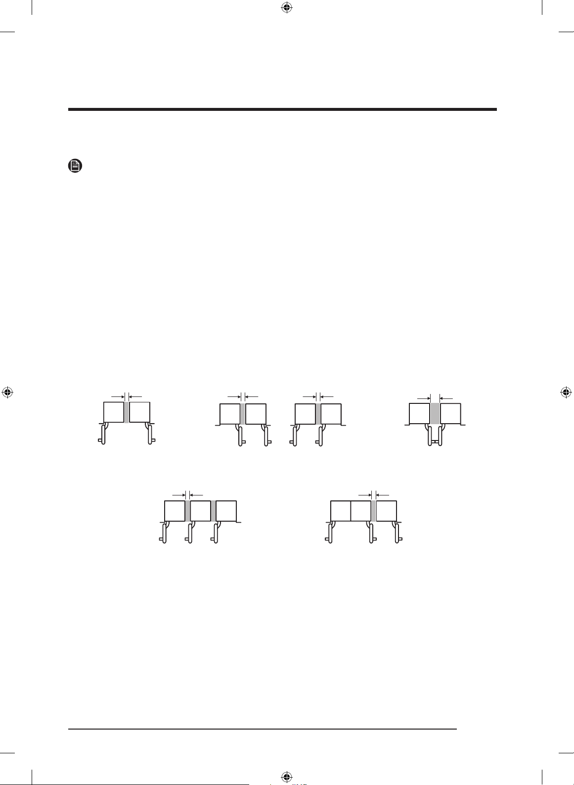
There are two panel-adjustment mechanisms at the top and two at the bottom of the door.
Adjust the panel so it aligns with the surrounding cabinetry.
The gap between the cabinet and the panel must be:
• 1/8” (3 mm) on top
• 1/8” (3 mm) on the side for single installation
• 5/32” (4 mm) on the side for pair installation
1/8” 1/8”
1/8” 1/8” 5/32” 5/32” 5/32”
English52
Dacor_BRW9000R_IM_DA68-03621J-02_EN.indd 52 2020-10-19 10:53:11
Page 53

The gap between the glass door and the
Glass Door
panel must be same on all sides (top,
bottom, left, and right) or the difference
should be no more than 2/32" (2 mm). (For
A B
Panel
example, if A is 2 mm, B should not exceed
4 mm.)
Top of the Door
1. Use the double-threaded bolts to align the door panel.
2. Engage a side screw (see the graphic) to shift the panel side to side.
3. Engage Screw 1 (see the graphic) to shift the panel forward/backward; engage Screw 2
to set the panel in place.
English 53
Dacor_BRW9000R_IM_DA68-03621J-02_EN.indd 53 2020-10-19 10:53:11
Page 54

Installation Instructions
1. Engage Double Threaded Bolt (see the graphic) to shift the panel up and down.
2. Engage a side screw (see the graphic) to shift the panel side to side.
CAUTION
Be careful not to damage the wires when fastening the side screw.
3. Engage Screw (backward) (see the graphic) to shift the panel forward/backward;
engage Screw (forward) to set the panel in place.
Panel-adjustment mechanisms
Each 12 screws per Door
M6x12 12 ea
Double-threaded bolt
Side screw
Screw (forward)
Screw (backward)
Panel-Adjustment Mechanism
English54
Dacor_BRW9000R_IM_DA68-03621J-02_EN.indd 54 2020-10-19 10:53:11
Page 55

Top of Door
Up/Low Left/Right Front/Rear
Bottom of Door
Left/Right Front/Rear
Attaching the Panel to the Door
1. Screw nuts snugly onto the double-threaded bolts.
2. Fasten the screws to assemble the panel and the door as shown in the figure.
Two nuts per set
M13
Six screws per side
(into the door)
Six screws per side
(into the panel)
English 55
Dacor_BRW9000R_IM_DA68-03621J-02_EN.indd 55 2020-10-19 10:53:12
Page 56

Installation Instructions
20. Attaching the Door’s Interior Covers
Upper Door Cover
1. Connect the humidity sensor connector,
and then arrange the wires as shown in
the figure.
Upper door cover
FIXER
2. Assemble the inner cover.
3. Insert both side rings of the door cap of
the upper door cover into the fixer.
English56
Dacor_BRW9000R_IM_DA68-03621J-02_EN.indd 56 2020-10-19 10:53:13
Page 57

Upper door cover
Upper door cover
M5x16 2 ea
4. Fasten the 2 screws to fix the upper
door cover.
English 57
Dacor_BRW9000R_IM_DA68-03621J-02_EN.indd 57 2020-10-19 10:53:13
Page 58

Installation Instructions
Lower Door Cover
1. Attach the air guide to the lower door cover (2 screws per set).
2. Attach the lower door cover by driving the screws from the front (2 screws per set).
3. Attach the caps over the screw holes.
Lower Door Cover
Caps
Lower Door Cover
(FH) M4x14 2 ea
English58
Dacor_BRW9000R_IM_DA68-03621J-02_EN.indd 58 2020-10-19 10:53:13
Page 59

21. Attaching Grill, Kickplate and Toe Kickplate (optional)
Attaching grill
• Drive the screws tightly on both sides to attach the grill.
Otherwise, the door may not close fully.
Attaching kickplate
• Drive the screws on both sides to attach the kickplate.
Kickplate
Kickplate
M4x8 2 ea
English 59
Dacor_BRW9000R_IM_DA68-03621J-02_EN.indd 59 2020-10-19 10:53:13
Page 60

Installation Instructions
Attaching Toe kickplate
• The height of the product can be adjusted between 83 3/8” ~ 84 3/8”.
• If you want to use the provided Dacor toe kickplate (4”), note that it was designed for a
product height of 83 7/8” and cabinet height of 84”.
• If you want to use a toe kickplate not provided by Dacor, adjust the height of the toe
kickplate accordingly.
• You can extend the bracket to move the kickplate by a max of 32 mm to the front.
Toe kickplate
Grill cover
Kickplate
Grill cover
BRACKET
Kickplate
Factory default 32 mm to the front
English60
Dacor_BRW9000R_IM_DA68-03621J-02_EN.indd 60 2020-10-19 10:53:13
Page 61

22. Attaching the Wine Cellar Trim
1. Cabinet-side trim: Attach the trim between the refrigerator and the cabinet.
WARNING
Please check again if there is any problem after installation.
Top View
Chassis
spacer
Cabinet-
side trim
2. Door-side trim: Attach trim to the door’s side bracket.
• Refer to figure 1- and secure the door side trim to the bracket. Make sure the trim is
properly seated.
• Refer to figure 2- and secure the door side trim to the door cover rib. Make sure the
trim is properly secured without any gap in between on both the top (figure 2-) and
the bottom (figure 2-).
WARNING
Please check again if there is any problem after installation.
Bracket Bracket
1
2
Door
Side Trim
Door Side Trim
Figure 1 Figure 2
Door Cover Rib
Upper
3
door
cover
Door
Side
Trim
Upper Lower
4
Lower
door
cover
Door
Side
Trim
English 61
Dacor_BRW9000R_IM_DA68-03621J-02_EN.indd 61 2020-10-19 10:53:14
Page 62

Installation Instructions
3. (Side-by-side installation only) Center trim: Attach the trim between the refrigerator
chassis.
WARNING
Please check again if there is any problem after installation.
Center trim
23. Attaching Trim Top Cover
Attach the Trim Top Cover on the bottom of the Top Cover.
• For pair installation, cut to fit the Trim Top Cover width and attach.
English62
Dacor_BRW9000R_IM_DA68-03621J-02_EN.indd 62 2020-10-19 10:53:14
Page 63

24. Assembling the Wine Rack
1. Remove the packaging of the bottom
wine shelf, and then place it on the
bottom of the wine cellar.
2. Remove the rail fixer.
English 63
Dacor_BRW9000R_IM_DA68-03621J-02_EN.indd 63 2020-10-19 10:53:14
Page 64

Installation Instructions
3. Hold the front part of the wine rack and
Make sure the hooks on the both rails are
properly inserted into the rack.
4. Fix the front part of the wine rack by
the rail, and then push the wine rack so
that the hook on the back of the rail is
inserted into the hole on the back of the
wine rack as shown in the figure.
NOTE
placing the rack on the front of the rail
so that two pins on the top and side of
the rack is inserted into the holes on
the front part of the rack as shown in
the figure.
NOTE
Make sure the pins on the both rails are
properly inserted into the holes on the
rack.
English64
Dacor_BRW9000R_IM_DA68-03621J-02_EN.indd 64 2020-10-19 10:53:15
Page 65

Bottle Presenter
3 ea
5. Place 3 Bottle Presenter on the wine
rack of the Presentation Zone.
6. Slide in the wine rack until you hear a
clicking sound.
English 65
Dacor_BRW9000R_IM_DA68-03621J-02_EN.indd 65 2020-10-19 10:53:15
Page 66

Installation Instructions
WARNING
• Make sure the appliance is level. If the appliance is not level, the wine rack may slide in
or out.
• Make sure the wine rack is firmly fixed.
25. Disassembling the Wine Rack
1. Pull the wine rack.
2. Gently spread the racks and lift the
front part to release from the pins.
3. Pull the wine rack to remove.
English66
Dacor_BRW9000R_IM_DA68-03621J-02_EN.indd 66 2020-10-19 10:53:16
Page 67

26. Adjusting the Door Spring
Adjust the tension of the door spring according to the product size.
With a star-head screwdriver, turn the adjusting screw.
I = maximum spring tension
0 = no spring tension
27. Cleaning
Remove the protective vinyl.
English 67
Dacor_BRW9000R_IM_DA68-03621J-02_EN.indd 67 2020-10-19 10:53:16
Page 68

Installation Instructions
28. Installation Checklist
Ensure the wine rack functions properly and that the custom door panel aligns with the
surrounding cabinetry.
WARNING
• The following checklist should be completed by the installer to ensure that the wine
rack is safely and correctly installed, functions properly, and that no part of the
installation has been overlooked.
• Proper installation is the responsibility of the homeowner. The importance of proper
installation of your Dacor appliance cannot be overemphasized.
Installation Checklist
Has the unit been inspected for cosmetic damage?
Is the unit properly aligned with the adjacent cabinets?
Do all doors, drawers and shelves operate smoothly, without interference?
Has all packaging, tape, and literature been removed from inside and outside of the
appliance?
Is the power cable connected to a three-prong grounded electrical outlet that meets the
electrical specifications?
Has the unit been properly leveled?
Is the gap between the glass door and the panel appropriate? (Please refer to page 53.)
Has the anti-tip bracket been properly installed?
Has the auto door open system been function properly?
Do all refrigerator components function properly?
Has the warranty been activated on-line or the warranty card filled out and mailed?
Is the appliance level?
Is the wine rack firmly fixed?
Have you demonstrated to the user how to assemble and disassemble the wine rack
according to the user manual?
English68
Dacor_BRW9000R_IM_DA68-03621J-02_EN.indd 68 2020-10-19 10:53:16
Page 69

Memo
Dacor_BRW9000R_IM_DA68-03621J-02_EN.indd 69 2020-10-19 10:53:16
Page 70

Memo
Dacor_BRW9000R_IM_DA68-03621J-02_EN.indd 70 2020-10-19 10:53:16
Page 71

Memo
Dacor_BRW9000R_IM_DA68-03621J-02_EN.indd 71 2020-10-19 10:53:16
Page 72

Dacor ∙ 14425 Clark Avenue, City of Industry, CA 91745 ∙ Phone: (833) 353-5483 ∙ Fax: (626) 403-3130 ∙ www.dacor.com
DA68-03621J-02
Dacor_BRW9000R_IM_DA68-03621J-02_EN.indd 72 2020-10-19 10:53:16
Page 73

Cava incorporada
DRW24980RAP/LAP
Instrucciones de instalación
Dacor_BRW9000R_IM_DA68-03621J-02_MES.indd 1 2020-10-19 10:51:50
Page 74

Contenido
Antes de comenzar 4
Importante 4
Información de Atención al cliente 5
Si necesita ayuda 5
Instrucciones importantes de seguridad 6
Advertencia sobre la State of California Proposition 65 (solo EE.UU.) 6
Precauciones generales de seguridad 7
Información de seguridad y advertencias 11
Seguridad de la instalación 11
Especificaciones de instalación 13
Opciones de instalación 14
Especificaciones del producto 16
Especificaciones del panel personalizado 17
Especificaciones de la manija 18
Instalación 20
Requisitos de instalación 21
Preparación para la instalación 21
Conexión de la cava 24
Requerimientos especiales del gabinete 25
Español2
Dacor_BRW9000R_IM_DA68-03621J-02_MES.indd 2 2020-10-19 10:51:50
Page 75

Instrucciones de instalación 26
1. Desembalaje de la cava 26
2. Traslado de la cava 27
3. Preparación para la instalación 28
4. Colocación del soporte antivuelco 28
5. Retirar la cubierta superior de la puerta, placa de protección 31
6. Instalar aislantes a cada lado de la cava - Instalación simple 34
7. Instalar aislantes a cada lado del congelador, del refrigerador o de la cava
- Instalación lado a lado (Par) 35
8. Conectar los dos chasis 38
9. Ajuste del ángulo de apertura de la puerta 39
10. Colocación de la cava en su estructura 40
11. Remoción de las dos palancas 42
12. Nivelación de la cava 43
13. Colocación de las dos palancas 45
14. Colocación de la cubierta superior de la cava 46
15. Ajuste de la cava 47
16. Colocar los soportes del panel personalizado de la puerta 48
17. Colgar un panel personalizado 50
18. Preparar el panel para el ajuste 51
19. Alinear el panel 52
20. Colocar las cubiertas interiores de la puerta 56
21. Colocar la rejilla, la placa de protección y el zócalo (opcional) 59
22. Colocación del borde de la cava 61
23. Instalar el borde de la cubierta superior 62
24. Armado del soporte para botellas 63
25. Desarmado del soporte para botellas 66
26. Ajuste del resorte de la puerta 67
27. Limpieza 67
28. Lista de verificación de instalación 68
Español 3
Dacor_BRW9000R_IM_DA68-03621J-02_MES.indd 3 2020-10-19 10:51:50
Page 76

GUARDE ESTAS INSTRUCCIONES
Antes de comenzar
Importante
• El diseño general y/o los accesorios pueden
diferir dependiendo del modelo.
Instalador
• A fin de promover la seguridad y minimizar
problemas, lea este manual detenidamente
antes de iniciar la instalación. Deje este
manual al usuario.
• Escriba el modelo/número de serie del
electrodoméstico en este manual para
referencia en caso de servicio/mantenimiento.
• Los números de modelo/serie se
encuentran en la etiqueta informativa en el
compartimiento de la cava.
Usuario
• Conserve este manual para referencia
personal y para referencia de inspectores,
personal de servicio, etc.
Español4
Dacor_BRW9000R_IM_DA68-03621J-02_MES.indd 4 2020-10-19 10:51:50
Page 77

GUARDE ESTAS INSTRUCCIONES
Información de Atención al cliente
Si necesita ayuda
Si desea hacer alguna pregunta o tiene un problema con la instalación, comuníquese con su distribuidor
de Dacor® o con el Equipo de atención al cliente de Dacor. Si su electrodoméstico Dacor se encuentra
en garantía, comuníquese con Dacor Distinctive Service. Tenga el modelo/número de serie del
electrodoméstico a mano al llamar. (Estos números se encuentran en la etiqueta informativa ubicada en
el marco interno de la puerta derecha del refrigerador).
Centro de atención al cliente de Dacor
Teléfono: 833-35-ELITE (833-353-5483) EE.UU., Canadá
De lunes a viernes de 05:00 a.m. a 05:00 p.m. Hora del Pacífico
Sitio web: www.dacor.com/customer-care/contact-us
inserte aquí: Información del producto: knowledgebase.dacor.com
Todas las especificaciones están sujetas a cambios sin previo aviso. Dacor no asume responsabilidad
alguna por los cambios en las especificaciones.
© 2017 Dacor, todos los derechos reservados.
Español 5
Dacor_BRW9000R_IM_DA68-03621J-02_MES.indd 5 2020-10-19 10:51:50
Page 78

GUARDE ESTAS INSTRUCCIONES
Instrucciones importantes de seguridad
Las instrucciones importantes de seguridad y las advertencias que aparecen en estas instrucciones no
tienen por objeto cubrir todos los posibles problemas y condiciones que puedan ocurrir.
Utilice el sentido común y tenga precaución al instalar, mantener u operar este o cualquier otro
electrodoméstico.
Siempre póngase en contacto con el equipo de atención al cliente de Dacor por cualquier problema o
condiciones que no entienda. Consulte Información de Atención al cliente.
Etiquetas y símbolos de seguridad
Estas alertas están destinadas a llamar la atención sobre áreas importantes en el manual.
Siempre que vea estos símbolos o etiquetas, lea el mensaje atentamente antes de continuar.
PELIGRO
Riesgos inminentes que CAUSARÁN lesiones físicas graves o la muerte.
ADVERTENCIA
Riesgos o prácticas inseguras que PUEDEN causar graves lesiones personales o incluso la muerte.
PRECAUCIÓN
Riesgos o prácticas inseguras que PUEDEN causar lesiones personales leves o daños materiales.
Advertencia sobre la State of California Proposition 65 (solo EE.UU.)
ADVERTENCIA : Este producto contiene sustancias químicas que, según el Estado de California,
provocan cáncer, defectos congénitos u otros daños en la reproducción.
Español6
Dacor_BRW9000R_IM_DA68-03621J-02_MES.indd 6 2020-10-19 10:51:50
Page 79

GUARDE ESTAS INSTRUCCIONES
ADVERTENCIA - Refrigerante R600a
Este dispositivo contiene refrigerante de isobutano, R600a, un gas natural con alta compatibilidad
ambiental, a pesar de ser inflamable. Sírvase cumplir con las siguientes advertencias
• Al manipular, instalar y operar el electrodoméstico, debe evitar daños a las tuberías refrigerantes.
• Las tareas de reparación deben estar a cargo del personal de servicio autorizado por el fabricante y
los componentes deberán reemplazarse por repuestos autorizados por el fabricante.
• Los productos de refrigeración contienen refrigerantes, que en virtud de la legislación federal deben
retirarse antes de la disposición del producto.
• Mantenga las aberturas de ventilación del gabinete o estructura incorporada del electrodoméstico
libres de obstrucciones.
• Para evitar la creación de una mezcla de gas-aire inflamable en caso de una pérdida en el circuito
del refrigerante, el tamaño del lugar en el que se coloca el refrigerador depende de la cantidad
de refrigerante utilizado. El lugar debe tener 35.3 pies³ por cada 8 g de refrigerante R-600a en el
electrodoméstico.
• La ubicación de la instalación no debe estar expuesta a la luz solar directa y evite colocar cerca
cualquier electrodoméstico o fuente de calor, tales como estufas, hornos u hornillas, radiadores, etc.
• Si coloca dos productos uno junto al otro, por razones de seguridad, asegúrese de utilizar productos
certificados en atmósferas de gas explosivas.
• No utilice dispositivos mecánicos ni otros medios para acelerar el proceso de descongelamiento.
• No dañe el circuito del refrigerante.
• No utilice electrodomésticos eléctricos dentro del compartimiento de almacenamiento de alimentos
del electrodoméstico.
Precauciones generales de seguridad
PELIGRO
IMPORTANTE:
A fin de evitar que los niños queden encerrados o se sofoquen al desechar un electrodoméstico viejo:
• Retire las puertas.
• Deje los estantes en su lugar de manera tal que los niños no puedan entrar fácilmente al
electrodoméstico.
• Corte las clavijas del enchufe y descártelas.
• Corte el cable de alimentación y descártelo separado del electrodoméstico viejo.
Español 7
Dacor_BRW9000R_IM_DA68-03621J-02_MES.indd 7 2020-10-19 10:51:50
Page 80

GUARDE ESTAS INSTRUCCIONES
Instrucciones importantes de seguridad
Para evitar posibles explosiones o incendios, no guarde ni utilice vapores o líquidos inflamables o
explosivos (como gasolina) dentro o cerca de este o de cualquier otro electrodoméstico. También
mantenga los objetos que podrían explotar, como latas de aerosol, lejos de quemadores de estufa,
hornos y campanas de cocina. No almacene materiales inflamables o explosivos en gabinetes o áreas
adyacentes.
ADVERTENCIA
IMPORTANTE: Este electrodoméstico está equipado con un enchufe eléctrico de tres clavijas con
conexión a tierra para protección contra posibles riesgos de descarga eléctrica. Debe enchufarse en un
tomacorriente dedicado y con conexión a tierra. En caso de que solo haya disponible un tomacorriente
de dos clavijas, será responsabilidad del cliente reemplazarlo por un tomacorriente dedicado y
conectado a tierra adecuadamente.
• No enrosque ni doble el cable de alimentación eléctrica del electrodoméstico.
• Nunca desenchufe el electrodoméstico jalando el cable de alimentación.
• Siempre sostenga el enchufe con firmeza y jale para extraerlo del tomacorriente.
• Desconecte el electrodoméstico cuando no esté en uso.
• No instale, repare, modifique ni reemplace cualquier pieza del electrodoméstico a menos que así se
lo recomiende específicamente en la literatura que lo acompaña.
• Un técnico de servicio calificado debe realizar todas las demás reparaciones.
NO corte ni retire la tercera clavija (conexión a
tierra) del cable de alimentación eléctrica.
NO utilice un adaptador.
NO utilice un cable de alimentación que esté
pelado o dañado.
NO conecte el electrodoméstico a un alargue.
Mantenga el cable de alimentación alejado de
superficies calientes.
NOTA
• Utilice un tomacorriente con conexión a
tierra.
• No se recomienda el uso de un tomacorriente
con un interruptor de falla de conexión a
tierra.
Español8
Dacor_BRW9000R_IM_DA68-03621J-02_MES.indd 8 2020-10-19 10:51:51
Page 81

GUARDE ESTAS INSTRUCCIONES
ADVERTENCIA
• Para reducir el riesgo de incendio, descarga eléctrica, lesiones graves o muerte al utilizar el
electrodoméstico, siga las instrucciones básicas de seguridad, incluyendo las siguientes:
• Si recibe un producto dañado, comuníquese de inmediato con su distribuidor o fabricante. No instale
ni utilice un electrodoméstico dañado.
• Asegúrese de que el electrodoméstico se haya instalado correctamente de acuerdo con estas
instrucciones de instalación.
• Asegúrese de instalar los tomacorrientes de acuerdo con la ubicación de la fuente de alimentación.
• Los equipos de refrigeración y refrigerantes deben desecharse adecuadamente de manera
profesional y apropiada de acuerdo con los reglamentos y la legislación local actual que protegen
el medio ambiente. Esto corresponde a su viejo electrodoméstico y a su nueva unidad una vez que
llega al fin de su vida útil. NO deseche el electrodoméstico en un relleno sanitario ni con desechos
urbanos. Comuníquese con los centros de disposición de desechos locales para obtener información
acerca de cómo desechar los residuos reciclables.
• Tenga cuidado al manipular, mover, utilizar o desechar el electrodoméstico a fin de evitar daños al
sistema de refrigeración.
• No lo instale en exteriores ni en situaciones de humedad. Este electrodoméstico no ha sido diseñado
para su instalación en vehículos recreativos ni embarcaciones.
• Mantenga los materiales de embalaje alejados de los niños. Las láminas y bolsas plásticas pueden
provocar asfixia.
• Conecte el electrodoméstico a un circuito de 115 V, 15 A. controlado por un disyuntor o fusible. El
electrodoméstico debe tener su propio circuito con conexión a tierra.
• No enrosque ni doble el cable de alimentación eléctrica del electrodoméstico. Nunca desenchufe el
electrodoméstico jalando el cable de alimentación. Siempre sostenga el enchufe con firmeza y jale
para extraerlo del tomacorriente.
• Desconecte el electrodoméstico cuando no esté en uso.
• No instale, repare, modifique ni reemplace cualquier pieza del electrodoméstico a menos que así se
lo recomiende específicamente en la literatura que lo acompaña. Un técnico de servicio calificado
debe realizar todas las demás reparaciones.
• Antes de realizar cualquier tipo de reparación, corte el suministro eléctrico en el panel del disyuntor.
• Este electrodoméstico no debe ser utilizado por personas (incluido niños) con capacidades físicas o
sensoriales reducidas, o por personas que carezcan de experiencia y conocimientos, a menos que se
encuentren bajo la supervisión adecuada de un responsable de su seguridad. Los niños deben estar
supervisados, por su seguridad.
• No permita que nadie, incluso niños, se siente, pare o trepe sobre cualquier parte del
electrodoméstico, incluso la puerta. Hacerlo puede provocar daños, lesiones graves o la muerte.
Español 9
Dacor_BRW9000R_IM_DA68-03621J-02_MES.indd 9 2020-10-19 10:51:51
Page 82

GUARDE ESTAS INSTRUCCIONES
Instrucciones importantes de seguridad
• Si el cable de alimentación está dañado, debe ser reemplazado por el fabricante o por un técnico de
reparación calificado a fin de evitar riesgos de seguridad. No utilice los controles en forma indebida.
• Limpie el electrodoméstico regularmente como se indica en la sección Cuidado y limpieza del
Manual del usuario. Limpie el balde o cajón de hielo regularmente.
• Cuando el congelador esté funcionando, no toque las superficies internas de acero inoxidable con
las manos mojadas o húmedas, dado que la piel puede adherirse a las superficies muy frías.
• No utilice ningún tipo de equipo eléctrico dentro de los compartimientos de la cava.
• No obstruya ninguna de las ventilaciones o aberturas del electrodoméstico.
• A fin de evitar el riesgo de que el electrodoméstico caiga de costado es obligatorio sujetarlo
mediante los dos soportes antivuelco provistos.
• Utilice el electrodoméstico únicamente con el fin para el que ha sido diseñado: el almacenamiento
de alimentos y bebidas. No ha sido diseñado para el uso comercial o industrial.
• Al realizar la instalación tenga cuidado de que la caja de componentes eléctricos no esté dañada por
la desviación de la descarga.
• Sostenga la manija al abrir y cerrar la puerta.
• Al abrir y cerrar la puerta, tenga cuidado de no poner las manos en la entrada.
Español10
Dacor_BRW9000R_IM_DA68-03621J-02_MES.indd 10 2020-10-19 10:51:51
Page 83

Información de seguridad y advertencias
Seguridad de la instalación
ADVERTENCIA
• Antes de instalar la cava, conéctela a un tomacorriente y enciéndala para asegurarse de que
funcione.
• Elija un lugar alejado de los calefactores, las calderas o la luz solar directa.
• Instale la unidad donde el aire fluya libremente y donde la cava esté bien ventilada.
• Instale la unidad de modo que el aire fluya sin obstrucciones a través de la parrilla delantera. Si no
se asegura la circulación del aire, esto puede interferir con el funcionamiento normal del producto.
• Ciertos animales (roedores) pueden masticar el cable de alimentación y provocar un incendio; por lo
tanto, instale la unidad en un lugar donde los animales no puedan acceder.
• Si el gabinete está hecho de material blando (por ejemplo, yeso, etc.), puede tener una estructura
débil y dañarse. Por lo tanto, utilice un gabinete de material robusto y resistente.
• Instale la cava con un equipo de al menos 2 personas.
• Consulte las dimensiones del gabinete y prepárelo con buena circulación de aire.
• Utilice un gabinete que no se deforme debido a las emisiones de calor del producto o a la humedad
por la apertura y cierre de la cava.
NOTA
Esta es una cava de estilo “incorporado”, lo que significa que debe ser instalada dentro de un hueco en
gabinetes de cocina existentes.
Antes de mover la cava, despeje el camino hasta el lugar donde se instalará.
Verifique todas las dimensiones del producto y el radio de inclinación con cualquier puerta, pasillo,
escalera, esquina, etc., para asegurar un paso sin obstrucciones.
ADVERTENCIA
Peligro de caída
Este electrodoméstico es relativamente pesado en su parte superior y tiende a caerse cuando no se
instala en forma segura.
Mantenga las puertas cerradas con cinta adhesiva hasta que la cava esté en su posición final y lista
para ser asegurada en su lugar.
Hacen falta dos o más personas para trasladar e instalar la cava.
De lo contrario, podría sufrir lesiones graves o incluso la muerte.
Español 11
Dacor_BRW9000R_IM_DA68-03621J-02_MES.indd 11 2020-10-19 10:51:51
Page 84

Información de seguridad y advertencias
PELIGRO
Riesgo de explosión
Mantenga los materiales y vapores inflamables, como la gasolina, lejos de la cava.
No hacerlo puede provocar la muerte, una explosión o un incendio.
Español12
Dacor_BRW9000R_IM_DA68-03621J-02_MES.indd 12 2020-10-19 10:51:51
Page 85

Especificaciones de instalación
ADVERTENCIA
Respete todos los códigos y ordenanzas durante la planificación e instalación. Comuníquese con el
departamento de mantenimiento de edificios local para obtener más información.
ADVERTENCIA
Las conexiones eléctricas y de descarga a tierra deben cumplir con las partes pertinentes del código
eléctrico nacional y/u otros códigos eléctricos.
Este electrodoméstico incluye un cable de alimentación con un enchufe con conexión a tierra de tres
clavijas para una fuente de alimentación eléctrica de 115 Vac, 15 Amp. Enchúfelo únicamente en un
tomacorriente de tres clavijas, con conexión a tierra y de 115 Vac.
El electrodoméstico está equipado con un sistema de iluminación con lámparas LED de alta intensidad.
No mire fijo dichas lámparas cuando estén encendidas a fin de evitar daños a su visión.
Español 13
Dacor_BRW9000R_IM_DA68-03621J-02_MES.indd 13 2020-10-19 10:51:51
Page 86

Opciones de instalación
Existen diversas opciones de instalación.
Están limitadas únicamente por el diseño de la cocina.
Electrodoméstico individual
OK OK X
Lado a lado (Par)
OK X XX
Español14
Dacor_BRW9000R_IM_DA68-03621J-02_MES.indd 14 2020-10-19 10:51:52
Page 87

Electrodomésticos individuales con partición
NOTA
• El grosor mínimo de la partición es 1 1/4” (32 mm).
• A 1 1/4” (32 mm), el giro de la puerta debe efectuarse como en el caso 1.
• A más de 1 9/16” (40 mm), el giro de la puerta puede efectuarse en la misma dirección y el ángulo
de apertura debe ser de 90 grados como en el caso 2.
A más de 7 7/8” (200 mm) , el giro de la puerta puede efectuarse en dirección opuesta y el ángulo de
apertura debe ser de 90 grados como en el caso 3.
Para esta opción de instalación es recomendable instalar el tope de la puerta a 90 grados. Para
minimizar el grosor de la partición.
Si se desea un ángulo de apertura de la puerta de 115 grados, es recomendable la distancia de “F”
(página 16) para el grosor de la partición.
• El grosor de la partición depende de la profundidad de la manija. Las dimensiones anteriores son
aceptables para las manijas Dacor.
1 1/4” (32 mm) 1 9/16” (40 mm)
OK
Caso 1 Caso 2 Caso 3
1 9/16” (40 mm)
Es recomendable que el giro de apertura de las puertas
se efectúe hacia el mismo lado.
OK OK OK
1 9/16” (40 mm) 7 7/8” (200 mm)
1 9/16” (40 mm)
OKOK
El giro de apertura de la puerta de la columna
individual debe ser el mismo que el de la instalación
lado a lado.
Español 15
Dacor_BRW9000R_IM_DA68-03621J-02_MES.indd 15 2020-10-19 10:51:52
Page 88

Especificaciones del producto
B1
D2
D1
D
C
90°
AB
Leyenda 24”
A 23 3/4” (603 mm)
B (con panel) 25” (635 mm)
B1 (sin panel) 23 13/16” (605 mm)
C 83 3/8” (2118 mm)
D 23 5/8” (600 mm)
D1 24 7/8” (631 mm)
D2 27 9/16” (701 mm)
E 50 3/4” (1289 mm)
F 13 11/16” (348 mm)
G 49 11/16” (1261 mm)
F
E
115°
G
Español16
Dacor_BRW9000R_IM_DA68-03621J-02_MES.indd 16 2020-10-19 10:51:52
Page 89

Especificaciones del panel personalizado
H1
W2 W2
W1
H2
W3
H3
H4
Leyenda 24”
W1
W2
W3
H1
H2
H3
H4
23 3/4” (603 mm)
3 9/32” (83.5 mm)
17 5/32” (436 mm)
79 7/8” (2029 mm)
7 23/32” (196 mm)
62 25/32” (1594.5 mm)
9 3/8” (238.5 mm)
Grosor del panel
Peso máximo
55.0 lb (25 kg)
3/4” (19 mm)
No supere la carga máxima que el panel personalizado puede soportar. Antes de confeccionar el panel,
verifique la solidez del material del panel y la carga de los accesorios del panel.
24”
Panel personalizado
Peso máximo
55.0 lb (25 kg)
NOTA
• El grosor estándar del panel personalizado es de 3/4” (19 mm).
Español 17
Dacor_BRW9000R_IM_DA68-03621J-02_MES.indd 17 2020-10-19 10:51:52
Page 90

Especificaciones del producto
Especificaciones de la manija
Antes de instalar los paneles personalizados,
debe instalar las manijas de la puerta/cajón.
Manija
Tornillo
embutido
Panel
personalizado
Puerta/cajón del
electrodoméstico
Instalación de la manija para unidades con paneles
de puertas personalizados (Vista superior)
Los modelos con paneles personalizados, cuentan
con la ventaja de poder seleccionar un estilo de
manija de acuerdo con su gusto personal. Las
manijas no se proveen con los modelos para
paneles personalizados. Hay kits de manijas
selectos disponibles a través de su distribuidor
Dacor. Dacor no recomienda el uso de tiradores.
El fabricante del panel debe seleccionar
y comprar los tornillos necesarios para la
instalación. Las cabezas de los tornillos
deben embutirse en el panel a fin de evitar
interferencias durante el ajuste.
PRECAUCIÓN
Recomendamos instalar una manija para panel personalizado. Sin la manija, puede atraparse los dedos
al abrir o cerrar la puerta.
Español18
Dacor_BRW9000R_IM_DA68-03621J-02_MES.indd 18 2020-10-19 10:51:52
Page 91

Instalación de la manija de Dacor
ADVERTENCIA
Siga estas instrucciones para instalar la manija de Dacor. De lo contrario, la manija puede dañarse o
funcionar inadecuadamente.
1. Coloque el soporte reforzado de la manija en la parte trasera del panel de la puerta y luego coloque
la manija en la parte delantera del panel de la puerta.
2. Fije los 4 tornillos en los lados superior e inferior de la manija, tal como se muestra. No los apriete
excesivamente.
Panel
(PW) M4x16
4 uds.
Manija refuerzo
Manija
Español 19
Dacor_BRW9000R_IM_DA68-03621J-02_MES.indd 19 2020-10-19 10:51:53
Page 92

Instalación
ADVERTENCIA
No instale el electrodoméstico:
• en exteriores,
• en un ambiente con caída de agua.
El electrodoméstico es muy pesado:
Cava de 24” aprox. 397 lb / 180 kg
Sala de instalación
El electrodoméstico debe instalarse en una habitación seca y ventilada.
Instalación segura
El electrodoméstico es muy pesado y tiende a caer hacia adelante cuando la puerta está abierta.
No abra la puerta hasta que no haya ninguna posibilidad de que el electrodoméstico se caiga.
La manera más segura de instalar el electrodoméstico es utilizar los dispositivos antivuelco provistos.
Piso
La superficie inferior debe estar nivelada y uniforme a fin de garantizar que el electrodoméstico esté
instalado en forma segura y funcione correctamente.
La superficie inferior debe estar hecha de un material duro, no flexible para cubrir el peso del
electrodoméstico.
Alinear el electrodoméstico
A fin de garantizar que el electrodoméstico funcione correctamente, debe estar nivelado
adecuadamente.
Puerta de vidrio
Al mover o instalar el electrodoméstico, tenga cuidado de no dañar la puerta de vidrio.
Español20
Dacor_BRW9000R_IM_DA68-03621J-02_MES.indd 20 2020-10-19 10:51:53
Page 93

Requisitos de instalación
Preparación para la instalación
Piezas de instalación del gabinete
Utilizando la tabla que aparece en la siguiente página, verifique que todas las piezas de instalación
estén presentes al desembalar el electrodoméstico.
A
A1
Controle las piezas de instalación al desembalar el electrodoméstico.
A1 PALANCA - 2
A
A2-1 SOPORTE INFERIOR - 1
A2-2 SOPORTE SUPERIOR - 1
B PLACA DE PROTECCIÓN 1 2
C
D SOPORTE ANTIVUELCO
E BORDE CENTRAL - 1
F
G Estante para vinos 10 20
A2-1
A2-2
B
G
PIEZAS ÚNICA-INSTALACIÓN PAR-INSTALACIÓN
Cubierta superior del
refrigerador
BORDE LATERAL DEL
GABINETE
1 2
18”, 24”, 30”: 1
36”: 2
2 2
C
D
E
F
18”, 24”, 30”: 2
36”: 4
Español 21
Dacor_BRW9000R_IM_DA68-03621J-02_MES.indd 21 2020-10-19 10:51:53
Page 94

Requisitos de instalación
Piezas de instalación de la puerta
Utilizando la tabla que aparece a continuación, verifique que todas las piezas de instalación de la
puerta estén presentes al desembalar el electrodoméstico.
A'
B'
C'
D'
Controle las piezas de instalación al desembalar el electrodoméstico.
PIEZAS ÚNICA-INSTALACIÓN PAR-INSTALACIÓN
A’
B’ TAPA 2 4
C’
D’ SOPORTE DEL PANEL 2 4
TAPA INFERIOR DE LA
PUERTA
BORDE LATERAL DE LA
PUERTA
1 2
2 4
Tornillo y tuerca
M6x12 12 uds. (FH) M4x14 22 uds.
(TH) M4x16 24 uds. M4x35 3 uds.
M13 2 uds. Ø6x30 3 uds.
Español22
Dacor_BRW9000R_IM_DA68-03621J-02_MES.indd 22 2020-10-19 10:51:54
Page 95

Herramientas necesarias
N.° Herramienta N.° Herramienta
Destornillador eléctrico
1
8
Cinta métrica
2
9
Destornillador plano
3
10
Cortador (Tijera)
4
11
Llave ajustable
5
12
Destornillador Phillips
6
13
Alfombra protectora
Escalera de tijera
Plataforma móvil para el
electrodoméstico
Cutter
Nivel
Destornillador de estrella
Trinquete
7
3/8” (10 mm),
14
1/2” (13 mm)
Dacor_BRW9000R_IM_DA68-03621J-02_MES.indd 23 2020-10-19 10:51:56
Llave combinada
3/8” (10 mm),
1/2” (13 mm)
Español 23
Page 96

Requisitos de instalación
Conexión de la cava
PRECAUCIÓN
Las conexiones eléctricas y de descarga a tierra deben cumplir con las partes pertinentes del código
eléctrico nacional y/u otros códigos eléctricos.
Este electrodoméstico incluye un cable de alimentación con un enchufe con conexión a tierra de tres
clavijas para una fuente de alimentación eléctrica de 115 Vac, 15 Amp. Enchúfelo únicamente en un
tomacorriente de tres clavijas, con conexión a tierra y de 115 Vac.
BAJO NINGUNA CIRCUNSTANCIA CORTE O QUITE
LA TERCERA CLAVIJA (CONEXIÓN A TIERRA) DEL
CABLE DE ALIMENTACIÓN.
NO UTILICE UN ENCHUFE ADAPTADOR PARA
CONECTAR LA CAVA A UN TOMACORRIENTE DE
2 CLAVIJAS.
NO UTILICE UN CABLE PROLONGADOR CON ESTE
ELECTRODOMÉSTICO.
ADVERTENCIA
Riesgo de descarga eléctrica
Enchufe a un tomacorriente de 3 clavijas exclusivo, conectado a tierra.
No retire la clavija de conexión a tierra.
No utilice un adaptador.
No utilice un cable prolongador.
No seguir estas instrucciones puede provocar la muerte, un incendio o una descarga eléctrica.
Español24
Dacor_BRW9000R_IM_DA68-03621J-02_MES.indd 24 2020-10-19 10:51:57
Page 97

Requerimientos especiales del gabinete
Ubicación del
suministro eléctrico
D
5”
(127)
A : Ancho del gabinete
B : Profundidad del gabinete
C : Altura del gabinete
D : Ubicación del suministro eléctrico, ancho
E : Ubicación del suministro eléctrico, alto
A
A 24” (610 mm)
B 25” (635 mm)
Leyenda 24”
C
E
C 84” (2134 mm)
D 14” (356 mm)
E 80” (2032 mm)
B
• B : Incluye el panel de la puerta estándar de un grosor de 3/4”.
• La instalación dentro de un gabinete de este ancho permite que el borde de la cava se ajuste
directamente a los gabinetes cercanos.
Español 25
Dacor_BRW9000R_IM_DA68-03621J-02_MES.indd 25 2020-10-19 10:51:58
Page 98

Instrucciones de instalación
1. Desembalaje de la cava
Controle el electrodoméstico a fin de detectar daños provocados por el transporte.
No instale el electrodoméstico si presenta daños visibles.
Si tiene alguna inquietud, consulte a su distribuidor.
1. Retire las bandas de polipropileno, el embalaje de cartón, EPS y la bolsa.
2. Retire los soportes del pallet al retirar los tornillos (cinco por soporte).
10 uds.M6x10
Afloje los tornillos
PRECAUCIÓN
Tenga cuidado de no dañar el electrodoméstico al descargarlo del pallet.
3. Como se ilustra, inserte la carretilla de mano entre el electrodoméstico y el empaque de madera.
Mientras inclina el electrodoméstico hacia atrás, descárguelo del empaque de madera.
Parte inferior del electrodoméstico
Empaque de madera
Español26
Dacor_BRW9000R_IM_DA68-03621J-02_MES.indd 26 2020-10-19 10:51:58
Page 99

2. Traslado de la cava
ADVERTENCIA
El electrodoméstico es muy pesado. Al mover el refrigerador, todo el personal debe tener cuidado de no
lesionarse ni dañar el electrodoméstico.
1. Ajuste el refrigerador a un medio de transporte adecuado (preferentemente una plataforma
deslizable para electrodomésticos) y lleve el refrigerador junto al gabinete de instalación.
2. Mueva e instálelo con un mínimo de dos personas.
3. Tenga cuidado de evitar daños al piso. Los pisos delicados deben protegerse con una madera, cartón
duro o un material similar.
4. Antes de mover el refrigerador, verifique que pase por las aberturas de las puertas, escaleras y
obstrucciones en altura.
• RIESGO DE VUELCO: El refrigerador es grande, pesado y se vuelca fácilmente cuando no se lo sujeta.
Siempre mueva el refrigerador en posición vertical si fuera posible. Si no, muévalo boca arriba.
Cierre y fije las puertas durante el transporte.
ADVERTENCIA
Tenga cuidado de no dañar la caja de componentes eléctricos durante la instalación.
OK (Recomendado)
OK
OK
Español 27
Dacor_BRW9000R_IM_DA68-03621J-02_MES.indd 27 2020-10-19 10:51:58
Page 100

Instrucciones de instalación
3. Preparación para la instalación
Desempaque los materiales y accesorios de instalación.
Consulte la sección de preparación para la instalación del capítulo Requerimientos de instalación.
4. Colocación del soporte antivuelco
ADVERTENCIA
Para evitar que la unidad caiga hacia adelante, debe instalarse un soporte antivuelco. Antes de colocar
el soporte, asegúrese de que no haya cableado eléctrico ni tuberías en el área que atravesarán los
tornillos. Se requiere un soporte por electrodoméstico.
PRECAUCIÓN
Use siempre anteojos de seguridad y otros dispositivos o accesorios de protección necesarios al instalar
o trabajar con fijaciones.
Dacor no recomienda que fije el soporte antivuelco en mampostería liviana (por ej.: bloques, ladrillos) o
en cemento nuevo, sin curar.
Asegúrese de que la pared o el gabinete al que se ajustan los soportes sean lo suficientemente sólidos
como para soportar la carga de seguridad.
Pared de madera
M4x35
Pared de cemento
M4x35
ø6x30
Los soportes antivuelco deben extenderse al menos 2” (50 mm) por encima del electrodoméstico a fin
de fijarlo. Si no fuera posible cumplir con dicha longitud mínima por las condiciones estructurales, es
posible hacerlo al ajustar un separador (madera) detrás del ángulo antivuelco.
1. La altura del soporte se mide desde el piso y
depende de la altura del gabinete.
NOTA
Altura del soporte
= Altura del gabinete – 4 3/32” (104 mm)
2. Ajuste los soportes antivuelco. Asegúrese de
que los tornillos se ajusten bien al soporte.
Español28
Dacor_BRW9000R_IM_DA68-03621J-02_MES.indd 28 2020-10-19 10:51:59
 Loading...