

Dacor DRT366, DRT304 Planning Manual

DRT304S, DRT366S
Document # PG04-003 Revised 02/03/11 Page 1/4
30” and 36” Wide, Distinctive Series
Slide-in Gas Cooktops
WARNING
• Observe all governing codes and ordinances during planning
and installation. Contact your local building department for
further information.
• This appliance must be installed in accordance with the
accompanying installation instructions.
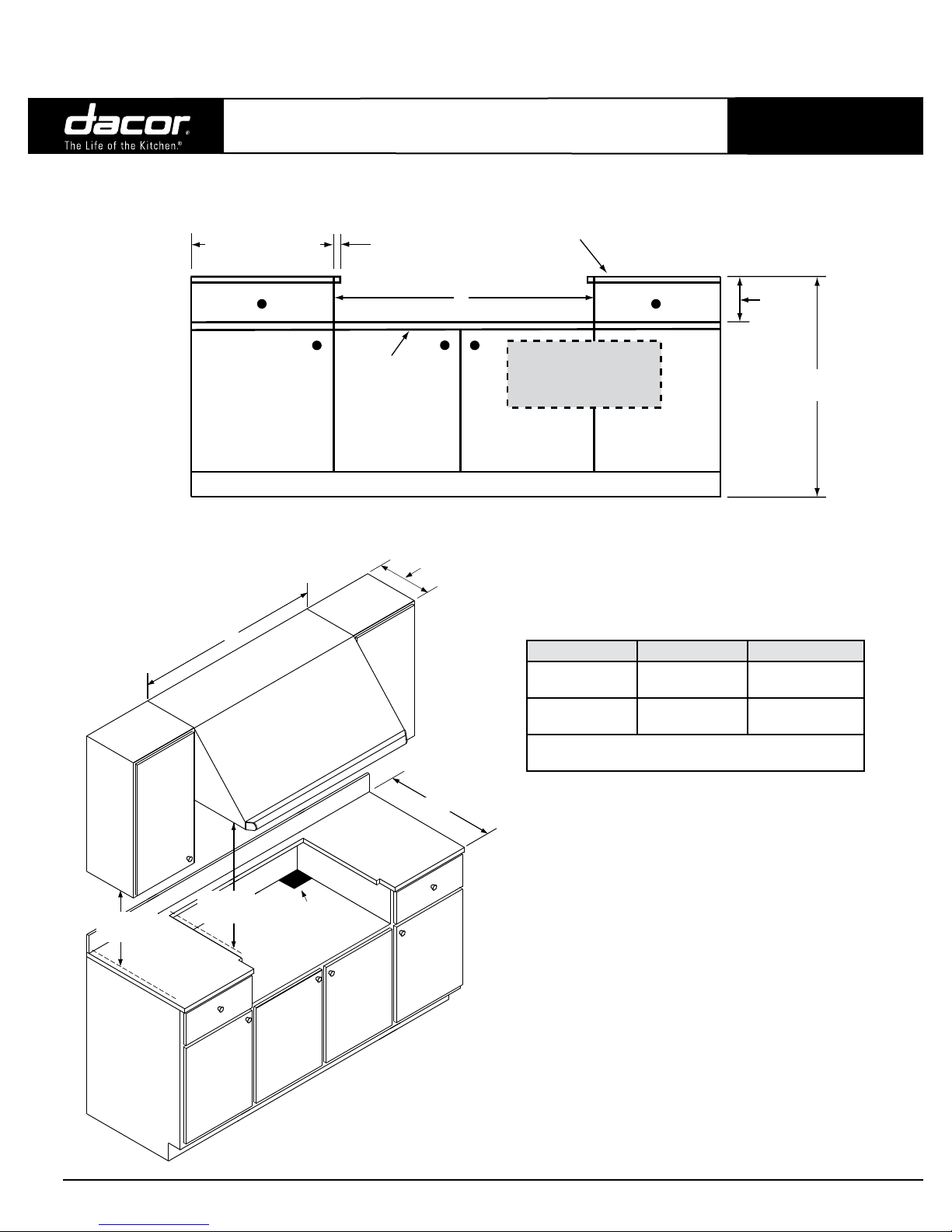
Product Dimensions
A
Product tolerances:
±1/16” (±1.6 mm)
unless otherwise noted
PLANNING
GUIDE
Electrical and Gas Supply Requirements
ELECTRIC CIRCUIT REQUIREMENTS
Circuit Required Total Connected Load
120 Vac 60Hz, 15 Amp. (3 wire) 1.0 Amp @ 120 Vac, 60 Hz.
GAS SUPPLY PRESSURE REQUIREMENTS*
Gas Type Manifold Pressure
Natural Gas 5” Water Column 6” Water Column
Propane (LP) 10” Water Column 11” Water Column
* Maximum gas supply pressure for all models is 1/2 p.s.i.
Cabinet and Countertop Layout
Installation of a non-combustible material* (up to the hood) or a backsplash
is always recommended, and mandatory if the distance to the back
wall from the cooktop is less than 2 1/2” (Figure 2). When installing a
backguard, use only Dacor model numbers AEB3009 (DRT304S), AEB3609
or AEB3612 (DRT366S).
Combustible
rear wall
2 1/2” (6.4 cm) min. to
combustible rear wall
Minimum Gas Supply
Pressure
COOKTOP WIDTH (A)
DRT304S 29 7/8” (75.9 cm)
DRT366S 35 7/8” (91.1 cm)
28 1/8” (71.4 cm)
25 7/8” (65.7 cm)
1 5/8” (4.1 cm) cooking surface
height (grate level) above
countertop
4” (10.2 cm)
Power cord
32” (81.3 cm) long
3/4” gas inlet, connects to regulator from
bottom or rear of unit, end is recessed
2” (5.1 cm) from chassis bottom
SIDE VIEW
Trim:
1/2”
(1.3 cm)
thick
7 3/4”
(19.7 cm)
5/8” min.
(1.6 cm)
SIDE VIEW WITHOUT BACKGUARD
Combustible
rear wall
Backguard mandatory if
gap from back of cooktop
to combustible wall is less
than 2 1/2”
SIDE VIEW WITHOUT BACKGUARD
Specications subject to change without notice. Phone: (800) 793-0093www.Dacor.com
4.14
DRT304S, DRT366S
Document # PG04-003 Revised 02/03/11 Page 2/4
30” and 36” Wide, Distinctive Series
Slide-in Gas Cooktops
Cabinet and Countertop Layout (Continued)
10” (25.4 cm) to
combustible side
wall min. both sides
CABINET/COUNTERTOP DIMENSIONS - FRONT VIEW
1/2” (1.3 cm)
Cooktop platform
1” (2.5 cm) min.
thickness
overhang,
both sides
13” (33.0 cm)
max.
PLANNING
GUIDE
1 1/2” (3.8 cm)
typical countertop
thickness
B
Recommended
gas and electrical
service location,
consult local code
3
Cabinet tolerances: +1/16”, -0 (+1.6 mm, -0)
unless otherwise noted.
7 3/4”
(19.7 cm)
36” (91.4 cm)
typical
18” (45.7 cm)
1, 3
min.
Top of
finished
counter
C
30” (76.2 cm)
1
min.
Hood
Cutout for
utility access
Model No. B C
DRT304S 30” (76.2 cm)
DRT366S 36” (91.4 cm)
* Minimum ** Recommended
See note 2
NOTE: Model DRT304S is not approved for installation
with a raised vent.
CABINET/COUNTERTOP DIMENSIONS -
1
Vertical to combustible surface from cooktop grate level;
if installing an overhead vent hood, also check the hood
specifications for minimum required clearances.
2
See Cabinet/Countertop Dimensions - Top View
3
Not applicable for cabinets more than a horizontal
distance of 10” (25.4 cm) from the edge of the cooktop.
30” (76.2 cm)*
36” (91.4 cm)**
36” (91.4 cm)*
42” (106.7 cm)**
ISO VIEW
Continued. on following page...
Specications subject to change without notice. Phone: (800) 793-0093www.Dacor.com
4.15
 Loading...