

Page 1

Equipment Installation Manual,
GDC31 Roll Steering Converter
EQUIPMENT INSTALLATION MANUAL
For the
GDC31 ROLL STEERING CONVERTER
P/N 1049-4000-XX-001( )
REV G
DAC International
6702 McNeil Drive
Austin, TX 78729
©Copyright 2004, DAC International. All rights reserved.
1049-2510-01 G.doc
1049-2510-01
Rev G Page 1 of 47
www.travelholidayhotel.com
Page 2
Equipment Installation Manual,
GDC31 Roll Steering Converter
RECORD OF REVISIONS
REV
DESCRIPTION DATE APPROVED
IR INITIAL RELEASE E266 4-5-04 LW
A Correct P/N of mating connector E269 4/8/04 L Wootton
B CHANGED BREAKER TO 2 AMPS E272-04 4/19/04 LW
C Reduced 28V and 14V install kits into one
7/26/04 LW
universal kit and added instructions for
configuration. Added wiring diagram for Bonanza
A-36. E306
D Omit approval pending E321 9/17/04 LW
E Add numerous wiring diagrams E327 10/22/04 LW
F Add additional wiring diagrams, correct table 4
3/30/05 LW
E389
G Add lighting bus circuit diagram to all wiring
5/20/05
CC
diagrams. Omit jumper on drawings Fig. 9 & 11.
Add note to installation section, page 16. E415
1049-2510-01 G.doc
1049-2510-01
Rev G Page 2 of 47
Page 3

Equipment Installation Manual,
GDC31 Roll Steering Converter
Table Of Contents
RECORD OF REVISIONS ...........................................................................................................................2
INTRODUCTION: ........................................................................................................................................5
DESCRIPTION:.............................................................................................................................................5
PART NUMBERS:........................................................................................................................................6
REGULATORY COMPLIANCE: ................................................................................................................6
Software .....................................................................................................................................................6
PMA...........................................................................................................................................................6
Environmental............................................................................................................................................6
SUPPLIED EQUIPMENT.............................................................................................................................7
OPTIONAL EQUIPMENT............................................................................................................................8
SPECIFICATIONS:.......................................................................................................................................9
Physical:.....................................................................................................................................................9
Electrical: ...................................................................................................................................................9
Serial Data Input: .....................................................................................................................................10
Roll Sum Steering Output:.......................................................................................................................10
ARINC 429 Output:.................................................................................................................................10
Reference Inputs: .....................................................................................................................................10
AP Offset Input:.......................................................................................................................................11
Annunciator Output: ................................................................................................................................11
Flag Input:................................................................................................................................................11
Certification: ............................................................................................................................................11
Reliability:................................................................................................................................................11
OPERATION:..............................................................................................................................................12
Overview..................................................................................................................................................12
Analog Output..........................................................................................................................................12
Reference Inputs (Excitation) .................................................................................................................12
ARINC 429 Output..................................................................................................................................12
GPS Mode Annunciator Control..............................................................................................................13
Super Flag Input.......................................................................................................................................13
INSTALLATION.........................................................................................................................................14
Material Not Supplied..............................................................................................................................14
Special Tools............................................................................................................................................14
Mounting Considerations.........................................................................................................................15
Wiring Considerations .............................................................................................................................15
Steering Output Scale Factor Determination...........................................................................................16
Configuration Pins ...................................................................................................................................17
Gain Setting Using Ref 1 input J1-18..................................................................................................17
Gain Settings Using Ref 2 input J1-6...................................................................................................17
Phase Selection ....................................................................................................................................18
1049-2510-01 G.doc
1049-2510-01
Rev G Page 3 of 47
Page 4

Equipment Installation Manual,
GDC31 Roll Steering Converter
Position/Rate Selection........................................................................................................................19
Baud Rate Selection.............................................................................................................................19
GPS Receiver Setup.............................................................................................................................19
REMOVAL AND REPLACEMENT..........................................................................................................20
Removal, GDC31.....................................................................................................................................20
Replacement, GDC31 ..............................................................................................................................20
Removal, Mode Annunciator...................................................................................................................20
Replacement, Mode Annunciator.............................................................................................................20
EQUIPMENT CHECKOUT........................................................................................................................21
Ground Functional Test ...........................................................................................................................21
Flight Functional Test..............................................................................................................................21
CONTINUED AIRWORTHINESS:............................................................................................................23
ENVIRONMENTAL:..................................................................................................................................24
CONNECTOR PIN OUT: ...........................................................................................................................25
OUTLINE DRAWINGS..............................................................................................................................26
GDC31 Outline ........................................................................................................................................26
Switch / Annunciator Outline ..................................................................................................................27
Isolation Coupler Outline.........................................................................................................................28
SLIDE LATCH ASSEMBLY......................................................................................................................29
APPENDIX A – AVIATION FORMAT.....................................................................................................30
APPENDIX B – 429 OUTPUT ...................................................................................................................31
Label 121 - Bank Angle Command .........................................................................................................31
Label 312 - Ground Speed .......................................................................................................................31
APPENDIX C - TYPICAL INTERCONNECT ..........................................................................................32
Figure 1 Typical Interconnect.................................................................................................................33
Figure 2 KI 525 / 525A with KA 52 / KA 57 ........................................................................................34
Figure 3 ARINC HSI with Century IV..................................................................................................35
Figure 4 ARINC HSI with S-TEC 50, 55 or 60.....................................................................................36
Figure 5 NSD 360A / NSD 1000 with Century IV................................................................................37
Figure 6 NSD 360A / NSD 1000 with S-TEC 50 or 55......................................................................... 38
Figure 7 ARINC HSI with Century II or III ..........................................................................................39
Figure 8 KI 525A with KFC 150 ...........................................................................................................40
Figure 9 NSD 360 with ARC 400B (10VAC)......................................................................................41
Figure 10 52D54 DG with STEC 50, 55 or 60 ......................................................................................42
Figure 11 NSD 360 with ARC 400B (DC)............................................................................................43
Figure 12 NSD 360 with Century 2000 .................................................................................................44
Figure 13 NSD 360A with Century II or III ..........................................................................................45
Figure 14 HSI-70C with ARC 1000 .....................................................................................................46
Figure 15 KI 525A with KFC 200 / 300...............................................................................................47
1049-2510-01 G.doc
1049-2510-01
Rev G Page 4 of 47
Page 5
Equipment Installation Manual,
GDC31 Roll Steering Converter
INTRODUCTION:
This Installation Manual contains installation data, specifications and Instructions for Continued
Airworthiness for the DAC International Model GDC31 Roll Steering Converter, Part Number 10494000-XX-001( ).
DESCRIPTION:
The GDC31 Roll Steering Converter with software version 001( ) is designed to receive RS232 or RS422
serial data from a GPS Navigation System to produce both an analog Roll Sum Steering (RSS) signal and
ARINC 429 labels bank angle command and ground speed.
The GDC31 output signal connects to the heading error input of the aircraft’s existing autopilot. The
GDC31 mimics the heading error signal of the aircraft’s installed HSI or DG. The GDC31 does not
reduce or otherwise alter any existing safety features of the autopilot, such as bank limiting, rate limiting
and protection from a hard over. The GDC31 provides lateral (roll) data only (no pitch data is supplied by
the GDC31). The ARINC 429 output can drive digital autopilots or converters.
The pilot simply selects between heading mode and GPS mode using the supplied switch / annunciator.
In heading mode, the autopilot operates as always, tracking the heading bug of the HSI or DG. In GPS
mode, the GDC31 RSS signal drives the autopilot’s heading channel. The GDC31 calculates the correct
course intercept angle from the data supplied by the GPS, smoothly guiding the aircraft onto the course.
The GDC31 then holds the aircraft on the selected course. If the GPS is programmed with Flight Plan
data, the GDC31 will calculate the new intercept angle at each waypoint change, intercepting and holding
the new course without pilot intervention.
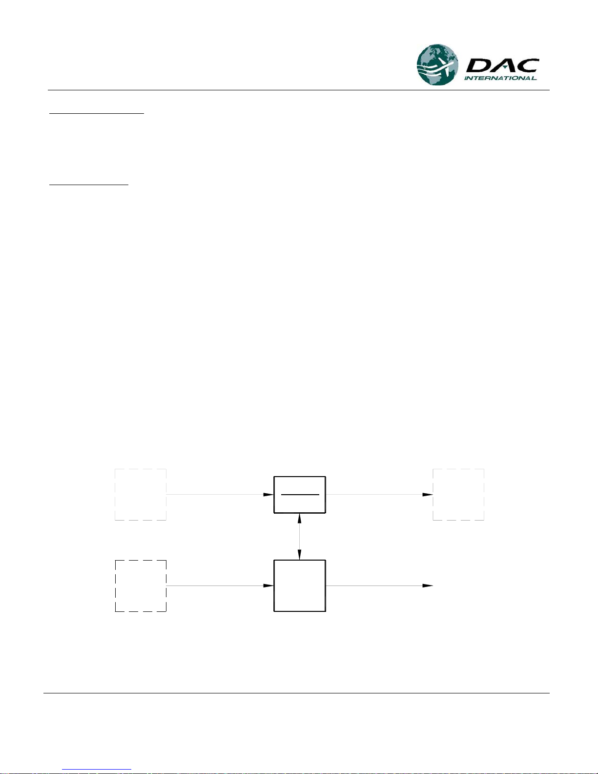
The GDC31 is designed to operate with both rate based and position based autopilots.
HDG ERROR
ANNUN / SW
HDG
HDG ERROR
HSI / CDI
GPS
ROLL STEERING
AUTOPILOT
SERIAL / FLAG
ARINC 429 OUT
(GS, BANK ANGLE)
GPS
GDC31 RSC
Block Diagram
1049-2510-01 G.doc
1049-2510-01
Rev G Page 5 of 47
Page 6

Equipment Installation Manual,
GDC31 Roll Steering Converter
PART NUMBERS:
The GDC31 Data Converter is available under the following part numbers:
1049-4000-01-
001( ) GDC31 Roll Steering Converter, ARINC 429 Low Speed
|
1049-4000-02-
001( ) GDC31 Roll Steering Converter, ARINC 429 High Speed
|
Software part number, where ( ) contains the number zero for initial release, or
any letter, A – Z to denote a minor change.
REGULATORY COMPLIANCE:
Software
The Model GDC31 software was developed in accordance with RTCA/DO-178B to criticality level C.
PMA
The Model GDC31 is approved via PMA.
Environmental
The Model GDC31 meets the DO-160D environmental categories listed later in this manual.
1049-2510-01 G.doc
1049-2510-01
Rev G Page 6 of 47
Page 7
Equipment Installation Manual,
GDC31 Roll Steering Converter
SUPPLIED EQUIPMENT
Each Data Converter is shipped with the following items:
Part Number Description Qty
1049-4000-01-001( ) GDC31 Roll Steering Converter, ARINC 429 Low Speed 1
1049-4200-10 Installation Kit, GDC31 Data Converter 1
Part Number Description Qty
1049-4000-02-001( ) GDC31 Roll Steering Converter, ARINC 429 High Speed 1
1049-4200-10 Installation Kit, GDC31 Data Converter 1
NOTE: The Annunciator / Switch, P10280, comes pre-configured for 28V operation. For 14V operation,
see the section titled INSTALLATION - Wiring Considerations.
Complete installation kits are available under kit part number 1049-4200-10. Individual pieces are
available under the part numbers shown. Contact DAC International sales to place orders.
Part Number Description Qty
1049-4200-10 Installation Kit, GDC31 Data Converter
M24308/2-3F Connector, Receptacle, 25 pin D-Sub 1
M39029/63-368 Socket, Crimp Style, female 25
P10219 Slide Latch Kit, shell size 3 1
P10220 Backshell, 25-Pin D-Sub 1
P10280 Mode Annunciator / Switch with 28V lamps 1
P10301 Lamp, 14V 4
1049-2510-01 Equipment Installation Manual for the GDC31 1
1049-2510-01 G.doc
1049-2510-01
Rev G Page 7 of 47
Page 8
Equipment Installation Manual,
GDC31 Roll Steering Converter
OPTIONAL EQUIPMENT
Certain installations require the use of an Isolation Coupler assembly. Refer to the applicable installation
drawings later in this manual for usage. This assembly is sold separately and comes with installation kit.
Part Number Description
1049-4801-01 Isolation Coupler
1049-4200-50 Installation Kit, Isolation Coupler
Complete installation kits are available separately under kit part number 1049-4200-50. Individual
pieces are available under the part numbers shown. Contact DAC International sales to place orders.
Part Number Description Qty
1049-4200-50 Installation Kit, Isolation Coupler
M24308/2-2F Connector, Receptacle, 15 pin D-Sub 1
M39029/63-368 Socket, Crimp Style, female 15
P10053 Slide Latch Kit 1
P10067 Backshell, 15-Pin D-Sub 1
1049-2510-01 G.doc
1049-2510-01
Rev G Page 8 of 47
Page 9

Equipment Installation Manual,
GDC31 Roll Steering Converter
SPECIFICATIONS:
Physical:
The GDC31 attaches to the airframe via four mounting holes. See the paragraph titled GDC31 Outline
Drawing for further details.
RSC LRU
Height.................................................1.25”
Width..................................................5.22” (Includes mounting flange)
Depth..................................................3.54”
Weight................................................0.4 lb.
The Isolation Coupler (optional) attaches to the airframe via four mounting holes. See the paragraph
titled Isolation Coupler Outline Drawing for further details.
Height.................................................1.25 in
Width..................................................4.5 in (Includes mounting flange)
Depth..................................................2.41 in”
Weight................................................0.2 lb.
Annunciator
Height.................................................0.753”
Width..................................................0.753” (Includes mounting flange)
Depth..................................................1.99”
Weight................................................0.05 lb.
Electrical:
Input Voltage .....................................14 / 28 VDC (10Vdc – 32Vdc operational)
Input Current......................................0.1 Amp maximum at 28 VDC
Annunciator lamp current..................0.04 Amp at 28 VDC, 0.08 Amp at 14 VDC
1049-2510-01 G.doc
1049-2510-01
Rev G Page 9 of 47
Page 10

Equipment Installation Manual,
GDC31 Roll Steering Converter
Serial Data Input:
Format................................................RS232 or RS422 serial data in RNAV 0, RNAV 1, King 0 or
King 1 format from a GPS navigation system
Baud Rate...........................................Selectable (2400, 4800, 9600, 19200)
Roll Sum Steering Output:
Description.........................................Analog bank angle command with program pin selectable scale
factors to match most autopilot input levels. Program pin
selection for position based or rate based output. Program pin
selectable phasing.
Load ...................................................1K
ARINC 429 Output:
Labels.................................................Bank Angle Command, Label 121
Ground Speed, Label 312
Baud Rate...........................................-01 Low Speed (12.5kBaud)
-02 High Speed (100 kBaud)
Reference Inputs:
General Description...........................AC or DC excitation used to excite the heading bug on the HSI
or DG. The GDC31 uses the reference input to produce a
steering signal with correct phase and amplitude characteristics.
Two reference inputs are provided. Use only one, depending on
the autopilot type. The unused input will be a no-connect. See
typical interconnect diagrams later in this manual.
AP Ref 1.............................................Reference voltage input for use with gain settings found in
Table 1.
Maximum Input Level ..................42 volts peak (30Vrms)
Load: ...........................................60K
AP Ref 2.............................................Reference voltage input for use with gain settings found in
Table 2.
Maximum Input Level ..................15 volts peak (10.6Vrms)
Load:............................................30K
1049-2510-01 G.doc
1049-2510-01
Rev G Page 10 of 47
Page 11

Equipment Installation Manual,
GDC31 Roll Steering Converter
AP Offset Input:
Autopilot Offset.................................For autopilots that use a signal common that is not airframe
ground. Many use 5Vdc (relative to airframe) as the heading
bug signal common. In these cases, connect the autopilot signal
common to the GDC31 offset input pin, P1-19.
Maximum Input Level ..................7 volts peak (5Vrms)
Load:............................................10K
Annunciator Output:
GPS Coupled......................................Normally Open relay contacts configured as a SPST switch
intended to control an external GPS mode annunciator. The
GDC31 closes the contacts when the steering output is valid. It
cycles the contacts between open and closed at a 1 Hz rate if
steering data is invalid. Closed contacts connect pins P1-24 and
P1-12.
Max current:.......................................250mA
Flag Input:
Description.........................................Valid input to the GDC31 at J1-25, supplied from a GPS
receiver Super Flag output (14 or 28V).
Voltage:..............................................Greater than 6V is valid, less than 3V is invalid.
Load ...................................................200K ohms
Certification:
PMA
DO-178B............................................Level C
DO-160D............................................D1/BADSXXXXXXABBBAVB/A3E3/XXX
Reliability:
MTBF.................................................Greater than 50,000 hours.
1049-2510-01 G.doc
1049-2510-01
Rev G Page 11 of 47
Page 12

Equipment Installation Manual,
GDC31 Roll Steering Converter
OPERATION:
Overview
The GDC31 Roll Steering Converter receives RS232 or RS422 serial data in RNAV 0, RNAV 1, King 0
or King 1 format from a GPS navigation system. It extracts Cross Track, Ground Speed and Track Angle
Error information from the data stream to compute an appropriate bank angle command to return the
aircraft to the Desired Track computed by the GPS navigation system.
Analog Output
The GDC31 produces an analog Roll Sum Steering (RSS) signal that drives the heading channel of the
autopilot. Phasing and amplitude of the RSS signal is based on the reference input supplied to the GDC31
from the autopilot and the gain and phase settings established by the program pins (refer to Tables 1, 2
and 3). The GDC31 will accept either an AC or a DC reference input as well as reference inputs that
contain an offset from airframe ground. The internal circuitry implements a multiplying Digital-toAnalog converter that uses the external reference input to produce the desired signal output amplitude and
phase relative to the reference input. Certain installations (Century II and III, for example) will not accept
a heading error signal referenced to ground, so require the Isolation Coupler in order to transformer
isolate the GDC31 output signal.
Reference Inputs (Excitation)
The GDC31 contains two reference inputs to accommodate the wide range of reference voltages
available. Input Ref1 will accommodate excitation voltages up to a maximum input of 42 volts peak
(30Vrms). Input Ref2 will accommodate excitation voltages up to a maximum of 15 volts peak (15Vdc
or 10.6Vrms). The determination of which reference to use will depend on the gain needed to match the
autopilot scale factor as well as the maximum expected reference voltage. Certain installations (Century
II and III, for example) produce a reference voltage that is floating relative to airframe ground. These
installation require the Isolation Coupler in order to transformer isolate the GDC31 reference input signal.
ARINC 429 Output
The GDC31 produces an ARINC 429 digital output containing labels 121 and 312 intended to drive
digital autopilots or digital autopilot converters.
429 Label Output
(Octal) Description Rate
121 Bank Angle Command (BNR) 20 Hz
312 Ground Speed (BNR) 20 Hz
1049-2510-01 G.doc
1049-2510-01
Rev G Page 12 of 47
Page 13

Equipment Installation Manual,
GDC31 Roll Steering Converter
GPS Mode Annunciator Control
The GDC31 contains a Normally Open relay contact configured as a SPST switch to control the external
GPS mode annunciator. This annunciator is further controlled by external switching and is active when
the pilot selects GPS mode in place of heading mode with the external switch. Refer to the typical
interconnect diagram later in this manual. If GDC31 output data is valid, the relay contacts are closed,
allowing the mode annunciator to illuminate. If the data is invalid, the GDC31 will cause the mode
annunciator to blink at a 1 Hz rate and command the steering output to zero degrees of bank (wings level).
The GPS mode annunciator blinks if either the super flag input is invalid or the serial data from the GPS
is missing or not the correct format (see Appendix A).
Super Flag Input
The GDC31 reads the Super Flag (14 or 28Vdc) from the GPS receiver. If the flag is greater than 5Vdc,
the flag shall be considered valid, if less than 2Vdc, the flag shall be considered as invalid. If the Super
Flag indicates invalid, the GDC31 shall produce a steering signal of zero degrees, blink the GPS
annunciator relay and invalidate the ARINC 429 label 121, bank command data, and label 312, ground
speed data.
1049-2510-01 G.doc
1049-2510-01
Rev G Page 13 of 47
Page 14

Equipment Installation Manual,
GDC31 Roll Steering Converter
INSTALLATION
This section provides details for the installation of the GDC31 Roll Steering Converter, including
configuration, wiring, mounting and checkout procedures. Follow the procedures and recommendations
found in this section to assure a successful installation.
Read this entire section before beginning the installation.
Prior to installation, determine the required scale factor and phasing for use with the aircraft’s autopilot.
Consider the location of the mode selector / annunciator switch; it should be installed within the pilot’s
primary field of view and easily accessible by the pilot.
Complete an electrical load analysis in accordance with AC 43.13-1B, Chapter 11 prior to starting the
aircraft modification to insure the aircraft has sufficient load capability.
Complete an aircraft weight and balance prior to aircraft modification to insure the aircraft has sufficient
weight and CG margin.
Material Not Supplied
The following items are required for the installation but not supplied:
• Wire: MIL-W-22759/16 or equivalent
• Shielded Wire: MIL-C-27500 or equivalent
• Mounting screws: MS35206 6-32, 4 each
• Circuit Breaker: Klixon 7277-2-2 or equivalent
• Tie straps or lacing cord
• Ring terminals (for grounding)
• Splices
Special Tools
Use the following crimp tool to ensure reliable crimp contact connections to connector J1.
• Crimp tool M22520/2-01
• Positioner M22520/2-08
1049-2510-01 G.doc
1049-2510-01
Rev G Page 14 of 47
Page 15

Equipment Installation Manual,
GDC31 Roll Steering Converter
Mounting Considerations
The GDC31 Roll Steering Converter can mount in the avionics bay, shelf or other suitable structure. It
can be mounted in any orientation.
The optional Isolation Coupler can mount in the avionics bay, shelf or other suitable structure. It can be
mounted in any orientation.
Attach the GDC31 and Isolation Coupler to suitable structure using the following hardware.
Screw, 8-32 X 1/2” MS35206-245
Flat Washer, #8 AN960-8L
Lock Washer, #8 MS35338-42
Nut, 8-32 MS35649-282
AN or MS self-locking nut plates may be used in place of the nut and lock washer specified above.
Mount the GPS/HDG mode annunciator / switch as near as practical to the autopilot mode controller. If
there is insufficient space there, mount the mode annunciator within the pilot’s primary field of view, near
the HSI or CDI.
Wiring Considerations
Wiring should be done in accordance with AC 43.13-1B, Chapter 11. Refer to the typical interconnect
diagram later in this manual for specifics. Use 22 to 24 AWG wire for all connections.
Fabricate wiring harness; refer to the interconnect diagrams and pin description. Test all the wiring for
continuity and for shorts. Insure aircraft power is on the correct pins of J1; refer to Table 6. Install slide
latch assembly onto J1 using instructions found later in this manual.
The mode annunciator/switch, P10280, comes pre-configured for 28V operation. For 14V operation,
perform the following steps:
1. Pull firmly on the edges of the lens to disengage the lamp assembly from the body. The lamp
assembly will hinge out and away from the body.
2. Remove and discard the four existing lamps, and replace with the four 14V lamps, P10301,
contained in the kit.
3. Push the lens firmly back into the body.
1049-2510-01 G.doc
1049-2510-01
Rev G Page 15 of 47
Page 16

Equipment Installation Manual,
GDC31 Roll Steering Converter
NOTE:
Perform the following setup procedures in this section if a wiring diagram for a particular autopilot is not
included in this manual.
Steering Output Scale Factor Determination
The GDC31 is designed to mimic the heading error signal produced by the existing HSI or DG, so it can
operate with the wide variety of autopilots in current use. These various autopilots employ a wide range
of reference voltages and scale factors to interface with the array of HSI and DG control heads.
Reference voltage, or excitation, is the autopilot signal used to excite the Heading Select bug in the HSI or
CDI. As used in this manual, scale factor refers to the autopilot’s response to the heading error input
signal, expressed in volts per degree of bank. Examples are 200mv/deg and 60mv/deg. Examples of
excitation voltage are 26Vac and 15Vdc. The GDC31 firsts computes the bank angle using data from the
GPS. It then uses the reference voltage along with the scale factor setting (gain setting) to produce a
signal that feeds into the autopilot’s heading error input to produce the desired bank angle.
The GDC31 has eight (8) choices for scale factor, selected with a combination of program pins (2 each)
and reference inputs (2 each). Tables 1 and 2 describe the program pin combinations for the various scale
factors. To determine the appropriate setting for a given autopilot, first determine the autopilot excitation
amplitude in volts (AC or DC). Next, determine the autopilot scale factor from the autopilot maintenance
data. The scale factor needs to be expressed as volts/degree of bank. Divide the scale factor by the
excitation (scale factor / excitation voltage). Then look in Tables 1 and 2 for the nearest Scaling value to
the one just computed.
If the gain is set too high, the commanded course intercept will be overly aggressive. For 90-degree
course changes, too much gain will often cause the aircraft to turn inside the new course then S-turn back
to capture the track.
If the gain is set too low, the commanded course intercept will be sluggish. For a 90-degree course
change, too little gain will often cause the aircraft to overshoot the desired course then S-turn back to
capture the track. Some autopilots limit the maximum bank angle to less than the 30 degrees, 22 degrees
for example. In these cases, the aircraft will exhibit the symptoms of too little gain because the aircraft
cannot turn sharp enough to capture the track without overshooting. Examine the attitude indicator during
a 90-degree course change to verify that the aircraft banks to 30 degrees, or in the case of rate based
autopilots, to a standard rate turn.
1049-2510-01 G.doc
1049-2510-01
Rev G Page 16 of 47
Page 17

Equipment Installation Manual,
GDC31 Roll Steering Converter
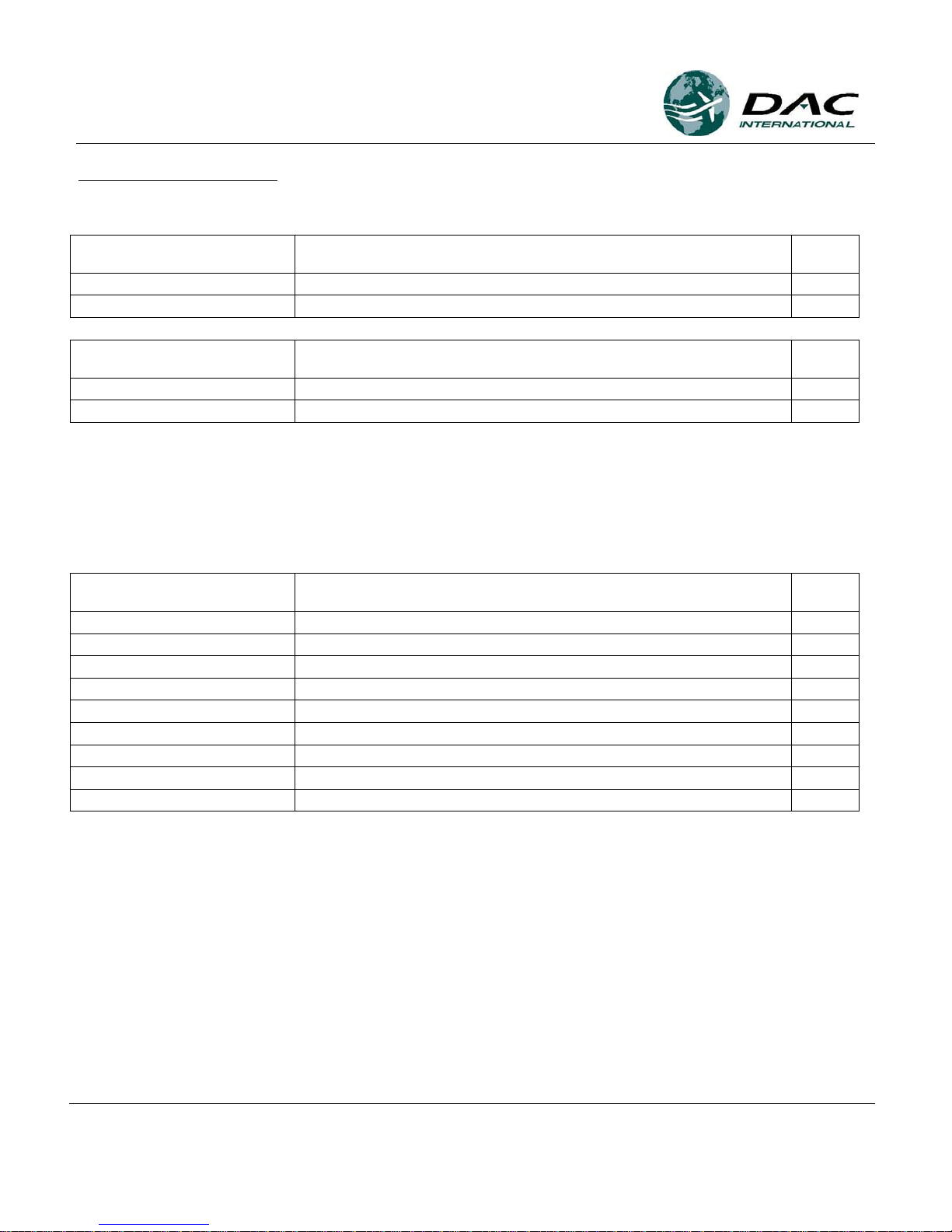
Configuration Pins
The GDC31 produces one of four (4) different RSS output levels for each reference input. This scaling
selection is accomplished with program pins J1-10 and J1-22. Tables 1 and 2 define the scale factors
available for each of the reference inputs, Ref 1 and Ref 2
Gain Setting Using Ref 1 input J1-18
Scaling J1-10 J1-22
0.015138 Open Open (1)
0.011590 Open Ground (1)
0.007687 Ground Open (1)
0.003844 Ground Ground (1)
Table 1
RSS Output Scaling Selection for Ref 1 input
(1) For 14 volt aircraft, maximum AC output signal is limited to 6.3 Vrms (210mV per degree) or
8.9 Vdc (297mV per degree.
Gain Settings Using Ref 2 input J1-6
Scaling J1-10 J1-22
0.033444 Open Open (2)
0.025606 Open Ground (2)
0.016983 Ground Open (2)
0.008492 Ground Ground (2)
RSS Output Scaling Selection for Ref 2 input
(2) For 14 volt aircraft, maximum AC output signal is limited to 6.3 Vrms (210mV per degree) or
8.9 Vdc (297mV per degree.)
Table 2
1049-2510-01 G.doc
1049-2510-01
Rev G Page 17 of 47
Page 18

Equipment Installation Manual,
GDC31 Roll Steering Converter
Phase Selection
The GDC31 will accommodate steering signals that are in phase with the reference or out of phase with
the reference. For DC heading error signals, in-phase means a positive error signal produces a right turn,
a negative error signal produces a left turn. Determine the correct phasing from the autopilot maintenance
data then wire P1-13 accordingly.
If the phasing is incorrectly wired, the autopilot will turn the opposite direction when coupled to the
GDC31 Roll Steering Converter.
Phase P1-13
IN Phase with Reference Open
OUT of Phase with Reference Ground
Table 3
Phase Selection
1049-2510-01 G.doc
1049-2510-01
Rev G Page 18 of 47
Page 19

Equipment Installation Manual,
GDC31 Roll Steering Converter
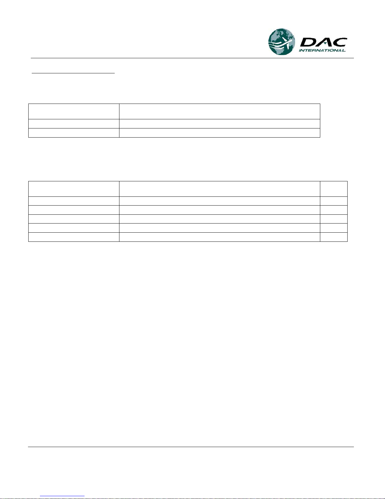
Position/Rate Selection
The GDC31 is designed to operate with both position based and rate based autopilots. Configuration is set
by program pin P1-23.
Scaling J1-23
Position Based Open
Rate Based Ground
Table 4
Position / Rate Selection
Position based autopilots require attitude information from the attitude indicator or vertical gyro. Rate
based autopilots require turn rate information from the turn coordinator rate gyro. Determine the autopilot
type, if it is rate based then connect J1-23 to program pin common, J1-11.
Baud Rate Selection
The GDC31 will accept four (4) baud rates for GPS data configured using program pins P1-9 and P1-21.
Baud Rate P1-9 P1-21
9600 Open Open
2400 Open Ground
4800 Ground Open
19200 Ground Ground
Table 5
Serial Baud Rate Selection
Note: Use Program Pin Common, J1-11, as ground for all program pin connections
GPS Receiver Setup
Refer to the manufacturer's instructions for the GPS interfaced to the GDC31 RSC. Configure the GPS to
output the Aviation Format data described in Appendix A.
1049-2510-01 G.doc
1049-2510-01
Rev G Page 19 of 47
Page 20

Equipment Installation Manual,
GDC31 Roll Steering Converter
REMOVAL AND REPLACEMENT
Removal, GDC31
1. Open the circuit breaker powering the GDC31.
2. Remove the connector by disengaging the slide latch then pulling the connector free.
3. Remove four (4) screws securing the unit to the airframe.
Replacement, GDC31
1. Open the circuit breaker powering the GDC31.
2. Attach the unit to the airframe with four (4) screws.
3. Seat the connector then engage the slide latch to secure.
4. Close circuit breaker.
5. Perform ground functional test found under Equipment Checkout in this manual.
Removal, Mode Annunciator
1. Open the circuit breaker powering the GDC31.
2. Pull firmly on the edges of the lens to disengage the lamp assembly from the body. The lamp
assembly will hinge out and away from the body.
3. Release the two (2) pawls by unscrewing the flat-head screws located inside the body.
4. Unplug the lamp module from the sleeve.
Replacement, Mode Annunciator
1. Open the circuit breaker powering the GDC31.
2. Plug the lamp module into the sleeve.
3. Secure by engaging the two (2) pawls to the sleeve.
4. Plug the lamp module into the body - it will snap into place.
5. Close the circuit breaker.
6. Perform ground functional test found under Equipment Checkout in this manual.
1049-2510-01 G.doc
1049-2510-01
Rev G Page 20 of 47
Page 21

Equipment Installation Manual,
GDC31 Roll Steering Converter
EQUIPMENT CHECKOUT
The GDC31 provides conversion of Serial data from a GPS receiver into a steering signal connected to
the autopilot heading channel through switching controlled by the HDG/GPS mode selector switch.
There are no other operator controls associated with the GDC31 unit.
The GPS receiver and the Autopilot must both be operational in order to perform this functional checkout.
Ground Functional Test
1. Insure that all control surfaces are clear and that the control wheel is centered in roll.
2. Apply power to the GPS Receiver and Autopilot.
3. Set the HDG/GPS Mode selector to HDG.
4. On the HSI, center the heading bug.
5. Engage the autopilot in Heading Mode.
6. Operate the heading bug; observe that the control wheel turns left and right in response to the
heading bug operation.
7. Center the control wheel using the heading bug.
8. Create and activate a flight plan in the GPS unit according to existing maintenance and / or flight
manual instructions.
9. Place the HDG/GPS Mode selector in the GPS position. Observe GPS illuminates and is not
blinking.
10. Remove power from the GPS receiver.
11. Observe that the GPS mode annunciator begins to blink within 15 seconds.
12. Verify that the control wheel centers once the GPS mode annunciator blinks.
13. Disengage the autopilot.
14. Ground test complete. Secure aircraft power.
Flight Functional Test
1. Set the HDG/GPS Mode selector to HDG.
2. On the HSI, center the heading bug.
3. Engage the autopilot in Heading Mode.
4. Operate the heading bug; observe that the control wheel turns left and right in response to the
heading bug operation.
5. Center the heading bug.
1049-2510-01 G.doc
1049-2510-01
Rev G Page 21 of 47
Page 22

Equipment Installation Manual,
GDC31 Roll Steering Converter
6. Create and activate a flight plan in the GPS unit according to existing maintenance and / or flight
manual instructions. Manually fly the aircraft until the cross track error is between 1 and 3 miles.
7. Place the HDG/GPS Mode selector in the GPS position. Observe that GPS illuminates and is not
blinking.
8. Observe that the aircraft turns to intercept the course selected in Step 6. Note: The GDC31 limits
the intercept angle to 45º maximum. (Intercept angle = difference between Desired Track and
Track.)
9. Observe that the aircraft captures the course without overshoot or undershoot.
10. Operate the heading bug; observe that the heading bug has no effect.
11. Select HDG on the HDG/GPS Mode selector.
12. Observe that the aircraft follows the heading bug.
13. Flight test complete.
1049-2510-01 G.doc
1049-2510-01
Rev G Page 22 of 47
Page 23

Equipment Installation Manual,
GDC31 Roll Steering Converter
CONTINUED AIRWORTHINESS:
This section provides data intended to assist the installer with establishing Instructions for Continued
Airworthiness as required by FARs 23.1529, 25.1529, 27.1529 and 29.1529.
1. Maintenance Manual information for the GDC31, which includes system description, removal
instructions, installation instructions and functional testing instructions, is contained in DAC
International Installation Manual, 1049-2510-01 (this document).
2. Line Replaceable Unit (LRU) part numbers and other parts contained in the installation data package
should be placed in the aircraft operator’s appropriate airplane illustrated Parts Catalog (IPC).
3. Wiring diagram information contained in the installation data package should be placed in the aircraft
operator’s appropriate airplane Wiring Diagram Manual.
4. Scheduled Maintenance Program tasks are as follows:
a. Recommended Periodic Scheduled Servicing: ........................... None required
b. Recommended Periodic Scheduled Preventive
Maintenance Tests....................................................................... None Required
c. Recommended Periodic Inspections: .......................................... None Required
d. Recommended Periodic Overhaul Period ................................... None Required
e. Special Inspection Requirements................................................ None Required
5. Application of Protective Treatments.................................................... None Required
6. Special Tools.......................................................................................... None Required
7. Electrical Loads for this appliance are as specified in the DAC International Installation Manual,
1049-2510-01 (this manual).
8. There are no Airworthiness limitations associated with the installation of this appliance.
1049-2510-01 G.doc
1049-2510-01
Rev G Page 23 of 47
Page 24

Equipment Installation Manual,
GDC31 Roll Steering Converter
ENVIRONMENTAL:
The GDC31 meets the environmental test categories detailed below in accordance with
RTCA/DO-160D,
Environmental Conditions and Test Procedures for Airborne Equipment.
NOMENCLATURE: Model GDC31 Roll Steering Converter
PART NO: 1049-4000-XX-XXXX
MANUFACTURER: DAC International
ADDRESS: 6702 McNeil Drive, Austin, TX 78729
Section Category Remarks
4.0 Temperature and Altitude D1 50,000 Ft Temperature controlled
5.0 Temperature Variation B Partially controlled temperature
6.0 Humidity A Standard Humidity
7.0 Operational Shock and Crash Safety D Fixed wing
Curves L, M and C.
8.0 Vibration S
9.0 Explosion Proofness X Not Tested
10.0 Waterproofness X Not Tested
11.0 Fluids Susceptibility X Not Tested
12.0 Sand and Dust X Not Tested
13.0 Fungus Resistance X Not Tested
14.0 Salt Spray X Not Tested
15.0 Magnetic Effect A 0.3 meter to 1.0 meter
16.0 Power Input B Alternator / Rectifiers
17.0 Voltage Spike B 56 volts
18.0 AF Conducted Susceptibility – Power
Inputs
19.0 Induced Signal Susceptibility A
20.0 Radio Frequency Susceptibility
(Radiated and Conducted)
21.0 Emission of Radio Frequency Energy B
22.0 Lightning Induced Transient
Susceptibility
23.0 Lightning Direct Effects X Not Tested
24.0 Icing X Not Tested
25.0 ESD X Not Tested
B
V 50 volts/meter
A3E3
Fixed Wing – Turbojet, Turbofan,
Turboprop and reciprocating
Instrument Panel or Fuselage
Alternator / Rectifiers
1049-2510-01 G.doc
1049-2510-01
Rev G Page 24 of 47
Page 25

Equipment Installation Manual,
GDC31 Roll Steering Converter
CONNECTOR PIN OUT:
The GDC31 contains a single 25-pin male connector, J1, per MIL-C-24308. The mating connector, P1, is
described previously under the section “Equipment Supplied”.
Pin Signal Function
1 A+ 28 Vdc Primary Power
2 Serial Out RS232 Output
3 Serial In RS232 Input
4 Reserved (VPP)
5 AP-OUT Autopilot Output
6 AP-REF2 Autopilot Reference, 10.6Vac max (1)
7 TX-A ARINC 429 Transmit A
8 TX-B ARINC 429 Transmit B
9 BAUDSEL1 Serial Baud Rate Select 1
10 GAINSEL1 Autopilot Gain Select 1
11 Prog Pin Common Program Pin Common
12 GPS Lamp A GPS Mode Annun Relay Armature
13 Phase Select Phase select program pin
14 Power Common 28 Vdc Return
15 AP-COM Autopilot Common (ground)
16 Serial Common RS232 Common
17 Reserved (/PGM Enable)
18 AP-REF1 Autopilot Reference, 30Vac max (1)
19 AP-OFFSET Autopilot Offset Input (A/P Common) +6Vdc max
20 429 Shield ARINC 429 Shield Common
21 BAUDSEL0 Serial Baud Rate Select 0
22 GAINSEL0 Autopilot Gain Select 0
23 TYPESEL0 Rate Based Select
24 GPS Lamp B GPS Mode Annun Relay N.O. Contact
25 Super Flag In 14 / 28 Vdc valid flag from GPS
NOTES: Do not use pins labeled Reserved. These are for factory test and In-Circuit-Programming
(1) Connect only one reference. Refer to “Reference Inputs” section.
1049-2510-01 G.doc
Table 6
J1 Pin Description
1049-2510-01
Rev G Page 25 of 47
Page 26

Equipment Installation Manual,
GDC31 Roll Steering Converter
OUTLINE DRAWINGS
GDC31 Outline
Note: Dimensions are in inches.
1049-2510-01 G.doc
1049-2510-01
Rev G Page 26 of 47
Page 27

Equipment Installation Manual,
GDC31 Roll Steering Converter
Switch / Annunciator Outline
Note: Dimensions are in inches.
PIN OUT
(REAR VIEW)
PANEL CUTOUT
Outline for part number P10280
3
12
57
8
11
4
6
10
9
12
1049-2510-01 G.doc
1049-2510-01
Rev G Page 27 of 47
Page 28

Equipment Installation Manual,
GDC31 Roll Steering Converter
Isolation Coupler Outline
1049-2510-01 G.doc
1049-2510-01
Rev G Page 28 of 47
Page 29

Equipment Installation Manual,
GDC31 Roll Steering Converter
SLIDE LATCH ASSEMBLY
Assemble the slide latch mechanism, part number P10219 or P10053, onto the mating connector as
pictured using the hardware supplied with the slide latch.
NUT
LOCK W ASHER
FLAT WASH ER
CONNECTOR
SLIDE LA TCH
SCR EW
1049-2510-01 G.doc
1049-2510-01
Rev G Page 29 of 47
Page 30

Equipment Installation Manual,
GDC31 Roll Steering Converter
APPENDIX A – AVIATION FORMAT
The GDC31 accepts data in the RS232 Aviation Format produced by most GPS panel mount receivers.
Various manufacturers refer to this data as RNAV, KING or MAPCOM. The following table contains the
minimum data set required by the GDC31. The GDC31 is designed to disregard additional data records
transmitted from the GPS.
The preferred baud rate is 9600 baud, however, the GDC31 will accept 2400, 4800 or 19200 baud. Insure
the GDC31 is configured for the correct baud rate (refer to "Serial Baud Rate Selection" located earlier in
this manual)
Aviation Data Format Description
<STX> ASCII Start of Transmission character
… other data
C284<cr> track; in degrees magnetic (ex: 284º)
D162<cr> ground speed; in knots (ex: 162 kt)
GR0050<cr> crosstrack; L (left) or R (right) in hundredths of
nautical miles (ex: Right 0.5nm)
I2855<cr> desired track; in tenths of degrees (ex: 285.5º)
… other data
<ETX> ASCII End of Transmission character
1. Each data field ends in a <cr> or <cr> <lf>
2. <cr> - ASCII carriage return character (0D hex)
3. <lf> - ASCII line feed character (0A hex)
1049-2510-01 G.doc
1049-2510-01
Rev G Page 30 of 47
Page 31

Equipment Installation Manual,
GDC31 Roll Steering Converter
APPENDIX B – 429 OUTPUT
Label 121 - Bank Angle Command
Label 121 shall be formatted as follows:
3 2 3 1 3 0 2 9 2 8 2 7 2 6 2 5 2 4 2 3 2 2 2 1 2 0 1 9 1 8 1 7 1 6 1 5 1 4 1 3 1 2 1 1 1 0 0 9 0 8 0 7 0 6 0 5 0 4 0 3 0 2 0
P SSM S Roll Angle (two’s compliment if negative) PAD SDI Label 121
P = odd parity
SSM = sign status matrix
00 = fail/warning
11 = normal
S = sign bit, 0=positive roll angle
SDI = source/destination identifier (always zero)
Data Range: ±180°
Resolution: 0.01°
1
Label 312 - Ground Speed
Label 312 shall be formatted as follows:
3 2 3 1 3 0 2 9 2 8 2 7 2 6 2 5 2 4 2 3 2 2 2 1 2 0 1 9 1 8 1 7 1 6 1 5 1 4 1 3 1 2 1 1 1 0 0 9 0 8 0 7 0 6 0 5 0 4 0 3 0 2 0
P SSM S Ground Speed PAD SDI Label 312
P = odd parity
SSM = sign status matrix
00 = fail/warning
11 = normal
S = sign bit, 0=positive (always)
SDI = source/destination identifier (always zero)
Data Range: 0 to 4096 knots
Resolution: 0.125 knot
1049-2510-01 G.doc
1049-2510-01
Rev G Page 31 of 47
1
Page 32

Equipment Installation Manual,
GDC31 Roll Steering Converter
APPENDIX C - TYPICAL INTERCONNECT
The following section contains typical interconnect diagrams to aid in wiring the GDC31.
All wiring, wire gauge and wire type shall be according to the INSTALLATION section of this manual.
Mounting shall use the hardware called out in this manual or AN / MS equivalent fasteners.
NOTE:
Many autopilot units provide both an AC and a DC excitation signal. Verify the HSI or DG is connected
to the autopilot signal and reference as shown in that diagram. Refer to the HSI or DG manufacturer’s
data and the autopilot manufacturer’s data for additional information.
1049-2510-01 G.doc
1049-2510-01
Rev G Page 32 of 47
Page 33

Equipment Installation Manual,
GDC31 Roll Steering Converter
1049-2510-01 G.doc
1049-2510-01
Rev G Page 33 of 47
Figure 1 Typical Interconnect
14V OR 28 VDC BUS
GPS
TX OUT
SHIELD
2A
A+
3
16
GDC31
14
J1
1
<-RS232
SUPER FLAG OUT
25
10
8
6
4
7
HDG
1
5
3
2
GPS
11
12
EXCITATION
HDG ERROR IN
GROUND
AUTOPILOT
HDG ERROR FROM HSI / CDI
POWER COMMON
RX IN
SERIAL COMMON
BAUD SELECT 0
RSS OUTPUT
RSS COMMON
REF1
SWITCH / ANNUNCIATOR
P10280 (28V OR 14V)
REF2 6
AP OFFSET
SIGNAL REFERENCE
EXCITATION
9
21
22
BAUD SELECT 1
GAIN SELECT 0
SUPER FLAG IN
19
18
15
5
GAIN SELECT 1 10
TYPE SELECT 23
PHASE SELECT 13
PROGRAM PIN COMMON 11
1
2
3
4
PROGRAM PINS
GPS INTERFACE
AUTOPILOT INTERFACE 5
6
7
1
SEE TABLE 5
SEE TABLES 1 AND 2
2
SEE TABLE 4
3
SEE TABLE 3
4
FOR EXCITATION VOLTAGES GREATER THAN 15 VOLTS PEAK
5
6
FOR USE WITH AUTOPILOTS THAT USE A SIGNAL REFERENCE
7
SEE TABLES 1 AND 2
FOR EXCITATION VOLTAGES LESS THAN 15 VOLTS PEAK
SEE TABLES 1 AND 2
THAT IS A VOLTAGE ABOVE AIRFRAME COMON, TYPICALLY 5VDC
EXCITATION (15 Vpk to 42 Vpk)
EXCITATION (LESS THAN 15 Vpk)
8
ISOLATION COUPLER IS USED TO TRANSFORMER ISOLATE THE
GDC31 REFERENCE AND / OR OUTPUT FOR INSTALLATIONS WHERE
THESE SIGNALS ARE NOT REFERENCED TO AIRFRAME GROUND.
1049-4801-01
4
13
COUPLER
ISOLATION
12 14
11
296
10
5
13
2:1
2:1
2:1
2:1
LIGHTING VOLTAGE
24
12
GPS LAMP A
GPS LAMP B
Page 34

Equipment Installation Manual,
GDC31 Roll Steering Converter
1049-2510-01 G.doc
1049-2510-01
Rev G Page 34 of 47
Figure 2 KI 525 / 525A with KA 52 / KA 57
7
1
5
2
4
11
SWITCH / ANNUN
SHDG/CRS RETURN
RS232 OUT
SUPER FLAG
RS232 COM
GPS RECEIVER
HEADING ERROR
LIGHTING BUS
P
12
6
3
2
5
11
8
1
10
4
7
KI 525 / 525A
BENDIX/KING
SIGNAL GROUND
-15V
+15V
j
Y
f
P10280
8
3
12
6
10
GPS
HDG
68
10
3
25
16
15
14
1
19
24
6
12
5
RSC
2A
7277-2-2
F
KA 57
BENDIX/KINGRSS CONVERTER
GDC31
BENDIX/KING
F
K
5
C
1
2
KA 52
TO AUTOPILOT / RADIO COUPLER
Super Flag
Serial Com
Serial In
Lamp B
Lamp A
AP Out
Offset
Ref 2
AP Com
A+
A+
14 OR 28VDC
DAY
NIGHT
Page 35

Equipment Installation Manual,
GDC31 Roll Steering Converter
1049-2510-01 G.doc
1049-2510-01
Rev G Page 35 of 47
AP Com
Ref 1
AP Out
Lamp A
Lamp B
Prog Com
Gain Sel 0
Serial In
Serial Com
Super Flag
39
43
42
CENTURY IV
ID496 COMPUTER
5KHz EXCITATION
SIGNAL GROUND
HEADING ERROR
7
1
5
4
2
11
GPS
HDG
8
10
3
6
12
5
18
12
15
24
10
7
P10280
4
8
1
12
11
SWITCH / ANNUN
11
22
1
3
14
25
16
3
6
2
5
P2
25
1041A
26
23
22
WILCOX
24
J2
M
G
RD-444-447
SPERRY
J
H
N
GPS RECEIVER
SUPER FLAG
RS232 COM
RS232 OUT
NOTE: ID496 COMPUTER MUST BE ARINC TYPE ID496-X1XX2
GDC31
RSS CONVERTER
D
P201
KING
E
B
A
KPI-550
C
H
C
Y
X
E
X
C
.
Z
H
E
A
D
I
N
G
PN 101
D
E
B
C
A
COLLINS
LIGHTING BUS
A+
NIGHT
DAY
A+
2A
7277-2-2
RSC
14 OR 28VDC
Figure 3 ARINC HSI with Century IV
Page 36

Equipment Installation Manual,
GDC31 Roll Steering Converter
1049-2510-01 G.doc
1049-2510-01
Rev G Page 36 of 47
HDG
10
P10280
SWITCH / ANNUNCOLLINS
A
C
B
E
D
PN 101
H
E
A
D
I
N
G
Z
Y
X
E
X
C
.
C
H
RS232 OUT
RS232 COM
SUPER FLAG
LIGHTING BUS
C
B
A22
23
24
GPS RECEIVER
J
H
G
SPERRY
RD-444-447
P201
D
E
KING
KPI-550 1041A
25
P2
26
WILCOX
8
J2
N
M
6
12
3
10
60
S-TEC
7277-2-2
Super Flag
Serial Com
Serial In
Type Sel 0
Gain Sel 0
Prog Com
Lamp B
Lamp A
AP Out
Offset195
2
6
3
3
14
25
16
11
23
22
1
4
12
11
1
8
7
5
6
12
15
24
Ref 2
2A
RSC
46
8
5
RSS CONVERTER
11
2
1
GPS
GDC31
7
4
S-TEC
50
10
25
S-TEC
55
GROUND
HDG ERR IN
SIG COM
EXCITATION
A+
NIGHT
DAY
A+
14 OR 28VDC
Figure 4 ARINC HSI with S-TEC 50, 55 or 60
Page 37

Equipment Installation Manual,
GDC31 Roll Steering Converter
1049-2510-01 G.doc
1049-2510-01
Rev G Page 37 of 47
Figure 5 NSD 360A / NSD 1000 with Century IV
Phase Sel13
AP Com
Super Flag
Serial Com
Serial In
Gain Sel 0
Prog Com
Lamp B
Lamp A
AP Out
Offset
Ref 2
HEADING ERROR
COMMON
-14V
+14V13
36
43
GDC31
RSS CONVERTER CENTURY IV
ID496
5
12
6
24
19
22
11
1
14
15
16
25
3
49
HDG
GPS
10
6
12
3
8
P10280
19
20
NSD 360A
NSD 1000
7
4
10
1
8
11
5
2
3
6
12
21
LIGHTING BUS
GPS RECEIVER
RS232 COM
SUPER FLAG
RS232 OUT
SWITCH / ANNUN
11
4
2
5
1
7
A+
NIGHT
DAY
A+
14 OR 28VDC
RSC
7277-2-2
2A
Page 38

Equipment Installation Manual,
GDC31 Roll Steering Converter
1049-2510-01 G.doc
1049-2510-01
Rev G Page 38 of 47
7
1
5
2
4
11
SWITCH / ANNUN
RS232 OUT
SUPER FLAG
RS232 COM
GPS RECEIVER
LIGHTING BUS
21
12
6
3
2
5
11
8
1
10
4
7
NSD 1000
NSD 360A
19
20
P10280
8
3
12
6
10
GPS
HDG
31
3
25
16
14
1
11
23
19
24
12
5
RSC
2A
7277-2-2
RSS CONVERTER
GDC31
39
4
50
S-TEC
25 27
S-TEC
55
38
28
43
P1
15
6
Super Flag
Serial Com
Serial In
Type Sel 0
Prog Com
Lamp B
Lamp A
AP Out
Offset
Ref 2
AP Com
EXCITATION GND
+10VDC EXCITATION
HEADING ERROR
SIGNAL REF
60
P1
S-TEC
A+
NIGHT
DAY
A+
14 OR 28VDC
Figure 6 NSD 360A / NSD 1000 with S-TEC 50 or 55
Page 39

Equipment Installation Manual,
GDC31 Roll Steering Converter
1049-2510-01 G.doc
1049-2510-01
Rev G Page 39 of 47
SUPER FLAG 25
RSS CONVERTER
RS232 COM
RS232 OUT
LIGHTING BUS
H
E
A
D
I
N
G
ZC
CE
YXB
A
H
E
X
C
.
D
C24
E
B
A
P201
D
26
23
22
P2
25
GPS RECEIVER
6
14
3
16
1
13
5
2
3
12
11
22
11
15
24
J
N
G
H
M
J2
1
8
4
5
12
18
10
7
RD-444-447
SPERRY
PN 101
COLLINS KING
KPI-550 1041A
WILCOX
P10280
SWITCH / ANNUN
3
12
6
10
8
2
GPS
11
GDC31
4
HDG
1
5
7
1049-4801-01 CD 33 PIGTAILCD 33 PIGTAIL
HDG COM
ROLL EXCITATION
ROLL EXCITATION
HEADING ERROR
13
14
11
6
5
RSC
7277-2-2
2A
10
4
3
9
12
2
1
E
A
F
D
E
A
B
D
14 OR 28VDC
4
13
ISOLATION
COUPLER
12 14
11
2
9
6
10
5
CENTURY
IC388-3
CENTURY
IC388-MC
13
Super Flag
Serial Com
Serial In
Phase Sel
Gain Sel 0
Prog Com
Lamp B
Lamp A
AP Out
AP Com
Ref 1
A+
NIGHT
DAY
A+
Figure 7 ARINC HSI with Century II or III
Page 40

Equipment Installation Manual,
GDC31 Roll Steering Converter
1049-2510-01 G.doc
1049-2510-01
Rev G Page 40 of 47
Figure 8 KI 525A with KFC 150
A+
RS-232 OUT
RS-232 COM
SUPER FLAG
A+
RECEIVER
GPS
LIGHTING BUS
KI 525A
HDG ERROR
HDG/CRS REF
Y
-15VDC
P
S
+15VDC f
A1
7277-2-2
SERIAL COMMON
SUPER FLAG IN
SERIAL IN
16
25
3
E
KC-19(X) FLIGHT
COMPUTER
P19(X)2
10
A
45AP-OUT
3
Strap for GPS baud rate per
GDC31 installation manual
NIGHT
DAY
6
2
12
5
11
1
8
22 GAINSEL0
PHASE SELECT
TYPE SELECT
BAUDSEL1
BAUDSEL0
14
1
21
9
AP-OFFSET
23
19
13
PROG PIN COMMON
GAINSEL1
GPS LAMP B
11
10
24
GPS LAMP A
AP-REF2
AP-COM
12
6
15
RSS CONVERTERSWITCH / ANNUNC
P10280
10
7
GDC31
X
20
19
P19(X)1
F
KFC-150
6
RSC
2A
SIGNAL GND
CHASSIS GND
12
GPS
11
SWITCH / ANNUNC
SCHEMATIC
-15 VDC REG
HDG DATUM
DATUM REF
DATUM REF
+15 VDC REG
3
8
HDG
10
P10280
5
2
1
4
7
14 OR 28VDC
Page 41

Equipment Installation Manual,
GDC31 Roll Steering Converter
1049-2510-01 G.doc
1049-2510-01
Rev G Page 41 of 47
RS-232 OUT
RS-232 COM
SUPER FLAG
HDG SIGNAL
LIGHTING BUS
A+
Strap for GPS baud rate per
9 BAUDSEL1
BAUDSEL0
SERIAL IN
SERIAL COMMON
SUPER FLAG IN
Baud Rate Selection section
RECEIVER
GPS
16
25
3
1
14
21
RSC
7277-2-2
2A
7
5
1
4
2
11
SWITCH / ANNUNC
RSS CONVERTER
GAINSEL1
GAINSEL0
PHASE SELECT
TYPE SELECT
AP-OFFSET
GPS LAMP A
GPS LAMP B
AP-OUT
AP-REF2
PROG PIN COMMON
AP-COM
20
EXC
A+
NIGHT
DAY
21
11 24
6
2
5
3
12
10k
23
19
13
10
22
11
8
1
7
4
10
6
12
15
5
SWITCH / ANNUNC
P10280
NSD-360A
NSD-1000
IG-832 A/C
EXC 19
GDC31
8
19 400HZ RTN
AC HDG IN
CHASSIS GND
35
20
12
6
3
HDG
GPS
10VAC 400HZ
SPERRY/ARC-400B
CA-550A/FD
10VAC HEADING
DATUM
33
J1/P4 J2/P5
10
SCHEMATIC
P10280
14 OR 28VDC
Figure 9 NSD 360 with ARC 400B (10VAC)
Page 42

Equipment Installation Manual,
GDC31 Roll Steering Converter
1049-2510-01 G.doc
1049-2510-01
Rev G Page 42 of 47
1049-4801-01
11
GPS RECEIVER
LIGHTING BUS
RS232 OUT
RS232 COM
SUPER FLAG
12
2
6
5
3
4
5
6
EXCITATION
SIG REF
HDG ERROR
HDG
10
P10280
SWITCH / ANNUN
A
B
52D54
E
D
DG
12
3
6
1
8
4
7
3
2
1
11
2
GPS
COUPLER
ISOLATION
2
8
10
7
4
1
5
1
24 Lamp B
Serial Com
3 Serial In
Super Flag25
16
10 Gain Sel 1
Type Sel 0
1
14
23
Offset
Prog Com
19
11
15
7277-2-2
46
RSC
2A
GROUND
S-TEC
5
4
Ref 1
Lamp A
AP Out
12
18
5
GDC31
RSS CONVERTER
6
S-TEC
55
S-TEC
15
25
50 60
3
HDG ERROR
SIG REF
EXCITATION
8
A+
NIGHT
DAY
A+
14 OR 28VDC
Figure 10 52D54 DG with STEC 50, 55 or 60
Page 43

Equipment Installation Manual,
GDC31 Roll Steering Converter
1049-2510-01 G.doc
1049-2510-01
Rev G Page 43 of 47
20
19
NSD-360A
NSD-1000
IG-832 A/C
21
Strap for GPS baud rate per
Baud Rate Selection section
GPS
RECEIVER
SUPER FLAG
RS-232 COM
RS-232 OUT
A+
LIGHTING BUS
HDG SIGNAL
EXC
EXC
SERIAL IN
SERIAL COMMON
SUPER FLAG IN
16
25
14
3
1
7277-2-2
2A
DC HDG IN
CA-550A/FD
DC HEADING
DATUM
SPERRY/ARC-400B
-10VDC REG
+10VDC REG
SIGNAL GND
CHASSIS GND
NIGHT
DAY
A+
6
3
2
5
8
11
12
1
4
7
GAINSEL1
GAINSEL0
PHASE SELECT
TYPE SELECT
AP-OFFSET
BAUDSEL1
BAUDSEL0
23
9
21
19
22
13
10
GPS LAMP A
GPS LAMP B
AP-OUT
AP-REF2
PROG PIN COMMON
AP-COM
6
24
11
12
5
15
35
21
SWITCH / ANNUNC
10
P10280
RSS CONVERTER
GDC31
27
24
10
J1/P4
HDG
GPS
RSC
12
6
3
11
2
SWITCH / ANNUNC
SCHEMATIC
10
8
P10280
7
1
4
5
14 OR 28VDC
Figure 11 NSD 360 with ARC 400B (DC)
Page 44

Equipment Installation Manual,
GDC31 Roll Steering Converter
1049-2510-01
1049-2510-01 G.doc
Rev G Page 44 of 47
NSD-360A
NSD-1000
IG-832 A/C
RECEIVER
RS-232 COM
SUPER FLAG
A+
RS-232 OUT
GPS
LIGHTING BUS
A+
HDG SIGNAL 21
EXC
EXC
20
19
16 SERIAL COMMON
SUPER FLAG IN
25
CENTURY 2000
15 AP-COM
10k
Baud Rate Selection section
Strap for GPS baud rate per
NIGHT
6
11
12
DAY
2
3
5
1
8
AP-OFFSET
BAUDSEL1
BAUDSEL0
TYPE SELECT
21
SERIAL IN
14
3
1
9
23
19
PHASE SELECT
GPS LAMP A
GPS LAMP B
PROG PIN COMMON
11
GAINSEL1
GAINSEL0
13
22
10
AP-REF2
12
24
6
RSS CONVERTER
P10280
10
7
4
SWITCH / ANNUNC
CD175
GDC31
AP-OUT5
17
20
12
GPS
SCHEMATIC
SWITCH / ANNUNC
3
2A
7277-2-2
RSC
12
6
8
HDG
10
P10280
2
11
4
1
5
7
CD220
HDG CRS DC EXC (REG V+)
HDG CRS DC EXC GND
DC HEADING SIGNAL
SHIELD GND
29
45
49
50
14 OR 28VDC
Figure 12 NSD 360 with Century 2000
Page 45

Equipment Installation Manual,
GDC31 Roll Steering Converter
1049-2510-01 G.doc
1049-2510-01
Rev G Page 45 of 47
Figure 13 NSD 360A with Century II or III
SUPER FLAG 25
RSS CONVERTER
RS232 COM
RS232 OUT
LIGHTING BUS
GPS RECEIVER
6
14
3
16
1
13
5
2
3
12
11
22
11
15
24
20
21
19
1
8
4
5
12
18
7
10
IU445-003-17
IU445-004-11
P10280
SWITCH / ANNUN
3
12
6
10
8
2
GPS
11
GDC31
4
HDG
1
5
7
1049-4801-01 CD 33 PIGTAIL
ROLL EXCITATION
ROLL EXCITATION
HEADING ERROR
13
14
11
6
5
10
4
3
9
12
2
1
E
A
D
4
13
ISOLATION
COUPLER
12 14
11
2
9
6
10
5
CENTURY
IC388-2
13
Super Flag
Serial Com
Serial In
Phase Sel
Gain Sel 0
Prog Com
Lamp B
Lamp A
AP Out
AP Com
Ref 1
NSD-1000
NSD-360A
EXC
EXC
HDG SIGNAL
B HEADING ERROR
CD 33
CENTURY
IC388-2
A+
NIGHT
DAY
A+
14 OR 28VDC
RSC
7277-2-2
2A
Page 46

Equipment Installation Manual,
GDC31 Roll Steering Converter
1049-2510-01 G.doc
1049-2510-01
Rev G Page 46 of 47
Figure 14 HSI-70C with ARC 1000
1049-4801-01
11
GPS RECEIVER
LIGHTING BUS
RS232 OUT
RS232 COM
SUPER FLAG
12
2
6
5
3
4
HDG
10
P10280
SWITCH / ANNUN
T
S
HSI-70C
HH
JJ
12
3
6
1
8
4
7
3
2
1
11
2
GPS
COUPLER
ISOLATION
2
8
10
7
4
1
5
1
24 Lamp B
14 OR 28VDC
Serial Com
3Serial In
Super Flag25
16
1
14
15
7277-2-2
RSC
2A
5
4
Ref 1
Lamp A
AP Out
12
18
5
GDC31
RSS CONVERTER
6
ARC 1000
3
H
E
X
C
.
C
H
C
E
R
R
H
D
G
2
28
26VAC 400HZ
AC HDG SIG
AC HDG COM
A+
NIGHT
DAY
A+
Page 47

Equipment Installation Manual,
GDC31 Roll Steering Converter
1049-2510-01 G.doc
1049-2510-01
Rev G Page 47 of 47
SUPER FLAG
RS-232 COM
RS-232 OUT
HDG ERROR
SIGNAL GND
HDG/CRS REF
-15VDC
+15VDC
LIGHTING BUS
A+
1112
A+
7277-2-2
Strap for GPS baud rate per
GDC31 installation manual
RECEIVER
GPS
NIGHT
6
SUPER FLAG IN
SERIAL COM
25
16
BAUDSEL0
SERIAL IN
TYPE SELECT
AP-OFFSET
BAUDSEL1
21
14
3
1
9
19
23
RSC
14 OR 28VDC
2A
KFC-200 / KFC-300
COMPUTER
Y
DAY
12
2
3
5
11
1
8
P
S
j
10
4
7
PHASE SELECT
PROG PIN COMMON
GAINSEL1
GAINSEL0
GPS LAMP A
GPS LAMP B
AP-REF2
11
13
22
10
24
12
6
AP-OUT
AP-COM
15
5
SWITCH / ANNUNCKI 525A
f
A1
P10280
RSS CONVERTER
GDC31
K -15 VDC REG
SIGNAL GND
SCHEMATIC
3
6
10
8
1
GPS
HDG
2
5
4
7
SWITCH / ANNUNC
HDG DATUM
DATUM REF
P10280
DIRECTIONAL
GYRO
KG-102A
Y
+15 VDC REGH
Figure 15 KI 525A with KFC 200 / 300
 Loading...