


21 393-01
PNOZ s1
4 D Betriebsanleitung
4 GB Operating instructions
4 F Manuel d'utilisation
21 393-01PNOZ s1
Sicherheitsschaltgerät PNOZ s1
Das Sicherheitsschaltgerät dient dem sicherheitsgerichteten Unterbrechen eines Sicherheitsstromkreises.
Das Sicherheitsschaltgerät erfüllt Forderungen
der EN 60947-5-1, EN 60204-1 und VDE 01131 und darf eingesetzt werden in Anwendungen
mit
` NOT-AUS-Tastern
` Schutztüren
Zu Ihrer Sicherheit
Installieren und nehmen Sie das Gerät nur
`
dann in Betrieb, wenn Sie diese Betriebsanleitung gelesen und verstanden haben und
Sie mit den geltenden Vorschriften über Arbeitssicherheit und Unfallverhütung vertraut
sind.
Beachten Sie die VDE- sowie die örtlichen
Vorschriften, insbesondere hinsichtlich
Schutzmaßnahmen
` Durch Öffnen des Gehäuses oder eigen-
mächtige Umbauten erlischt jegliche Gewährleistung.
Gerätemerkmale
Relaisausgänge zwangsgeführt:
`
– 2 Sicherheitskontakte (S) unverzögert
` 1 Halbleiterausgang
` Anschlussmöglichkeiten für:
– NOT-AUS-Taster
– Schutztürgrenztaster
– Starttaster
` 1 Kontakterweiterungsblock PNOZsigma
über Verbindungsstecker anschließbar
` LED-Anzeige für:
– Versorgungsspannung
– Eingangszustand Kanal 1
– Eingangszustand Kanal 2
– Schaltzustand Sicherheitskontakte
–Startkreis
–Fehler
` Steckbare Anschlussklemmen (wahlweise
Federkraftklemme oder Schraubklemme)
Sicherheitseigenschaften
Das Schaltgerät erfüllt folgende Sicherheitsanforderungen:
` Die Schaltung ist redundant mit Selbstüber-
wachung aufgebaut.
` Die Sicherheitseinrichtung bleibt auch bei
Ausfall eines Bauteils wirksam.
` Bei jedem Ein-Aus-Zyklus der Maschine wird
automatisch überprüft, ob die Relais der Sicherheitseinrichtung richtig öffnen und
schließen.
` Das Gerät hat eine elektronische Sicherung.
Safety relay PNOZ s1
The safety relay provides a safety-related interruption of a safety circuit.
The safety relay meets the requirements of
EN 60947-5-1, EN 60204-1 and VDE 0113-1
and may be used in applications with
` E-STOP pushbuttons
` Safety gates
For your safety
Only install and commission the unit if you
`
have read and understood these operating
instructions and are familiar with the applicable regulations for health and safety at work
and accident prevention.
Ensure VDE and local regulations are met,
especially those relating to safety.
` Any guarantee is rendered invalid if the hous-
ing is opened or unauthorised modifications
are carried out.
Unit features
Positive-guided relay outputs:
`
– 2 safety contacts (N/O), instantaneous
` 1 semiconductor output
` Connection options for:
– E-STOP pushbutton
– Safety gate limit switch
– Reset button
` A connector can be used to connect 1
PNOZsigma contact expander module
` LED indicator for:
– Supply voltage
– Input status, channel 1
– Input status, channel 2
– Switch status, safety contacts
– Reset circuit
– Errors
` Plug-in connection terminals (either cage
clamp terminal or screw terminal)
Safety features
The relay meets the following safety requirements:
` The circuit is redundant with built-in self-
monitoring.
` The safety function remains effective in the
case of a component failure.
` The correct opening and closing of the safety
function relays is tested automatically in
each on-off cycle.
` The unit has an electronic fuse.
Bloc logique de sécurité PNOZ s1
Le bloc logique de sécurité sert à interrompre
en toute sécurité un circuit de sécurité.
Le bloc logique de sécurité satisfait aux exigences des normes EN 60947-5-1, EN 60204-1 et
VDE 0113-1 et peut être utilisé dans des applications avec des
` poussoirs d'arrêt d'urgence
` protecteurs mobiles
Pour votre sécurité
Vous n'installerez l'appareil et ne le mettrez
`
en service qu'après avoir lu et compris le
présent manuel d'utilisation et vous être familiarisé avec les prescriptions en vigueur
sur la sécurité du travail et la prévention des
accidents.
Respectez les normes locales ou VDE, particulièrement en ce qui concerne la sécurité.
` L'ouverture de l'appareil ou sa modification
annule automatiquement la garantie.
Caractéristiques de l'appareil
Sorties de relais à contact lié :
`
– 2 contacts de sécurité (F) instantanés
` 1 sortie statique
` Raccordements possibles pour :
– poussoir d'arrêt d'urgence
– interrupteur de position
– poussoir de réarmement
` Un bloc d'extension de contacts PNOZsig-
ma raccordable par l'intermédiaire d'un connecteur enfichable
` LED de visualisation pour :
– tension d'alimentation
– Etat d'entrée canal 1
– Etat d'entrée canal 2
– Etat de commutation des contacts de sé-
curité
– Circuit de réarmement
– Erreurs
` Borniers débrochables (au choix avec rac-
cordement à ressort ou à vis)
Caractéristiques de sécurité
Le relais satisfait aux exigences de sécurité
suivantes :
` La conception interne est redondante avec
une autosurveillance.
` Le dispositif de sécurité reste actif, même en
cas de défaillance d'un composant.
` L'ouverture et la fermeture correctes des re-
lais internes sont contrôlées automatiquement à chaque cycle marche/arrêt de la
machine.
` L'appareil est équipé d'une sécurité électro-
nique.
D.3.E. ELECTRONIQUE - Parc d ’Activité SAVIPOL - B.P. 55 - 10302 SAINTE SAVINE
Téléphone 03.25.71.31.50 - Télécopie 03.25.74.38.82 – Email : electronique@d3e.fr
- 1 -

Blockschaltbild/Klemmenbelegung Block diagram/terminal configuration Schéma de principe/affectation des
bornes
A1 A2
=
Input
=
Power
Reset/
Start
S34
Mitte: Frontansicht mit Abdeckung
Rechts: Frontansicht ohne Abdeckung
Funktionsbeschreibung
Einkanaliger Betrieb: keine Redundanz im
`
Eingangskreis, Erdschlüsse im Start- und
Eingangskreis werden erkannt.
` Automatischer Start: Gerät wird aktiv, nach-
dem Eingangskreis geschlossen wurde.
` Manueller Start: Gerät wird aktiv, wenn der
Eingangskreis geschlossen ist und danach
der Startkreis geschlossen wird.
` Kontaktvervielfältigung und -verstärkung
durch Verdrahtung von Kontakterweiterungsblöcken oder externen Schützen möglich;
1 Kontakterweiterungsblock PNOZsigma
über Verbindungsstecker anschließbar.
Montage
Grundgerät ohne Kontakterweiterungsblock montieren:
` Stellen Sie sicher, dass der Abschlussstek-
ker seitlich am Gerät gesteckt ist.
Grundgerät und Kontakterweiterungsblock
PNOZsigma verbinden:
` Entfernen Sie den Abschlussstecker seitlich
am Grundgerät und am Kontakterweiterungsblock.
` Verbinden Sie das Grundgerät und den Kon-
takterweiterungsblock mit dem mitgelieferten Verbindungsstecker bevor Sie die Geräte
auf der Normschiene montieren.
Montage im Schaltschrank
` Montieren Sie das Sicherheitsschaltgerät in
einen Schaltschrank mit einer Schutzart von
mindestens IP54.
` Befestigen Sie das Gerät mit Hilfe des Rast-
elements auf der Rückseite auf einer Normschiene.
` Sichern Sie das Gerät auf einer senkrechten
Normschiene (35 mm) durch ein Halteelement (z. B. Endhalter oder Endwinkel).
` Vor dem Abheben von der Normschine das
Gerät nach oben oder unten schieben.
23
13
K1
unit
Interface
expansion
K2
Y32
Centre: Front view with cover
Right: Front view without cover
14
24
Function description
Single-channel operation: no redundancy in
`
the input circuit, earth faults in the reset and
input circuit are detected.
` Automatic start: Unit is active once the input
circuit has been closed.
` Manual reset: Unit is active once the input
circuit is closed and then the reset circuit is
closed.
` Increase in the number of available contacts
by connecting contact expander modules or
external contactors/relays;
A connector can be used to connect 1
PNOZsigma contact expander module.
Installation
Install base unit without contact expander
module:
` Ensure that the plug terminator is inserted at
the side of the unit.
Connect base unit and PNOZsigma contact
expander module:
` Remove the plug terminator at the side of the
base unit and at the contact expander module.
` Connect the base unit and the contact ex-
pander module to the supplied connector
before mounting the units to the DIN rail.
Installation in control cabinet
` The safety relay should be installed in a con-
trol cabinet with a protection type of at least
IP54.
` Use the notch on the rear of the unit to attach
it to a DIN rail.
` Ensure the unit is mounted securely on a ver-
tical DIN rail (35 mm) by using a fixing element (e.g. retaining bracket or an end angle).
` Push the unit upwards or downwards before
lifting it from the DIN rail.
Schéma du milieu : vue frontale avec capot de
protection
A droite : vue frontale sans capot de protection
Description du fonctionnement
Commande par 1 canal : pas de redondance
`
dans le circuit d'entrée, les mises à la terre
dans les circuits de réarmement et d'entrée
sont détectées.
` Réarmement automatique : l'appareil est ac-
tivé dès que le circuit d'entrée est fermé.
` Réarmement manuel : l'appareil est activé
lorsque le circuit d'entrée est fermé et après
que le circuit de réarmement se soit fermé.
` Augmentation et renforcement possibles du
nombre de contacts par câblage des blocs
d'extension de contacts ou des contacteurs
externes ;
1 bloc d'extension de contacts PNOZsigma
raccordable par connecteur.
Montage
Installer l'appareil de base sans bloc d'extension de contacts :
` Assurez-vous que la fiche de terminaison est
insérée sur le côté de l'appareil.
Raccorder l'appareil de base et le bloc d'extension de contacts PNOZsigma
` Retirez la fiche de terminaison sur le côté de
l'appareil de base et sur le bloc d'extension
de contacts.
` Avant de monter les appareils sur le rail DIN,
reliez l'appareil de base et le bloc d'extension de contacts à l'aide du connecteur fourni.
Montage dans une armoire
` Montez le bloc logique de sécurité dans une
armoire électrique ayant un indice de protection d'au moins IP54.
` Montez l'appareil sur un rail DIN à l'aide du
système de fixation situé sur la face arrière.
` Fixez l'appareil monté sur un rail DIN vertical
(35 mm) à l'aide d'un élément de maintien
(par exemple : un support terminal ou une
équerre terminale).
` Avant de retirer l'appareil du rail DIN, pous-
sez l'appareil vers le haut ou vers le bas.
- 2 -

Verdrahtung
Beachten Sie:
` Angaben im Abschnitt "Technische Daten"
unbedingt einhalten.
` Die Ausgänge 13-14, 23-24 sind Sicherheits-
kontakte.
` Vor die Ausgangskontakte eine Sicherung
(s. techn. Daten) schalten, um das Verschweißen der Kontakte zu verhindern.
` Berechnung der max. Leitungslänge I
Eingangskreis:
R
lmax
=
I
max
Rl / km
= max. Gesamtleitungswiderstand
R
lmax
(s. techn. Daten)
/ km = Leitungswiderstand/km
R
l
` Leitungsmaterial aus Kupferdraht mit einer
Temperaturbeständigkeit von 60/75 °C verwenden.
` Sorgen Sie an allen Ausgangskontakten bei
kapazitiven und induktiven Lasten für eine
ausreichende Schutzbeschaltung.
Wiring
Please note:
` Information given in the “Technical details”
must be followed.
` Outputs 13-14, 23-24 are safety contacts.
` To prevent contact welding, a fuse should be
connected before the output contacts (see
technical details).
` Calculation of the max. cable runs l
input circuit:
im
max
R
lmax
=
I
max
Rl / km
= max. overall cable resistance (see
R
lmax
technical details)
R
/km = cable resistance/km
l
` Use copper wire that can withstand 60/75
°C.
` Sufficient fuse protection must be provided
on all output contacts with capacitive and inductive loads.
max
Raccordement
Important :
` Respectez impérativement les données indi-
quées dans le chapitre « Caractéristiques
techniques ».
` Les sorties 13-14, 23-24 sont des contacts
de sécurité.
` Protection des contacts de sortie par des fu-
in the
sibles (voir les caractéristiques techniques)
pour éviter leur soudage.
` Calcul de la longueur de câble max. I
le circuit d'entrée :
R
lmax
=
I
max
Rl / km
= résistance max. de l'ensemble du
R
lmax
câblage (voir les caractéristiques techniques)
R
/km = résistance du câblage/km
l
` Utilisez uniquement des fils de câblage en
cuivre résistant à des températures de 60/75
°C.
` Assurez-vous du pouvoir de coupure des
max
contacts de sortie en cas de charges capacitives ou inductives.
Betriebsbereitschaft herstellen Preparing for operation Mettre l'appareil en mode de marche
Anschluss Connection Connexion
` Versorgungsspannung ` Supply voltage ` Tension d'alimentation
Versorgungsspannung/power supply/tension
d'alimentation
AC DC
A1
S1
L+
sur
A2
L-
` Eingangskreis ` Input circuit ` Circuit d'entrée
Eingangskreis/input circuit/circuit d'entrée einkanalig/single-channel/monocanal zweikanalig/dual-channel/à deux canaux
NOT-AUS
ohne Querschlusserkennung/
E-STOP
A1
S1
L+
without detection of shorts across contacts/
arrêt d'urgence
sans détection des courts-circuits entre les
canaux
Schutztür
ohne Querschlusserkennung/ safety gate
without detection of shorts across contacts/
protecteur mobile
sans détection des courts-circuits entre les
A1
S1
L+
canaux
` Startkreis/Rückführkreis ` Reset circuit/feedback loop ` Circuit de réarmement/Boucle de retour
Startkreis/Rückführkreis/
reset circuit/feedback loop/
circuit de réarmement/boucle de retour
automatischer Start/
automatic reset/
réarmement automatique
Startkreis/reset circuit/circuit de réarmement Rückführkreis/feedback loop/boucle de retour
A1
S34
A1
S34
13 (23)
14 (24)
K5
K6
K5
K6
L1
N
manueller/überwachter Start/
manual/monitored reset/
réarmement manuel/réarmement auto-contrôlé
A1
S34
- 3 -
S3
A1
S34
13 (23)
14 (24)
K5
K6
K5
K6
S3
L1
N

` Halbleiterausgang ` Semiconductor output ` Sortie statique
*
Y32
PLC Input
*Verbinden Sie die 0-V-Anschlüsse aller externen Netzteile miteinander.
INFO
Die Verdrahtung zwischen einem Grundgerät und einem Kontakterweiterungsblock
PNOZsigma erfolgt ausschließlich über den
Verbindungsstecker.
Betrieb
Das Gerät ist betriebsbereit, wenn die LED Power permanent leuchtet.
LEDs zeigen den Status und Fehler während
des Betriebs an:
LED leuchtet
LED blinkt
INFO
Statusanzeigen und Fehleranzeigen können unabhängig voneinander auftreten. Bei
einer Fehleranzeige leuchtet oder blinkt die
LED "Fault" (Ausnahme: "Versorgungsspannung zu gering"). Eine zusätzlich blinkende LED weist auf eine mögliche
Fehlerursache hin. Eine zusätzlich statisch
leuchtende LED weist auf einen normalen
Betriebszustand hin. Es können mehrere
Statusanzeigen und Fehleranzeigen gleichzeitig auftreten.
Statusanzeigen Status indicators Affichages d'état
Power, In1, In2
Eingangskreis ist geschlossen.
Out
Sicherheitskontakte sind geschlossen und
Halbleiterausgang Y32 führt High-Signal.
Reset
An S34 liegt 24 V DC an.
Fehleranzeigen Error indicators Affichage des erreurs
Fault
Diagnose: Abschlussstecker nicht gesteckt
` Abhilfe: Abschlussstecker stecken, Ver-
sorgungsspannung aus- und wieder einschalten.
Fault
Diagnose: Interner Fehler, Gerät defekt
` Abhilfe: Versorgungsspannung aus- und
wieder einschalten, gegebenenfalls Gerät tauschen.
Power
Diagnose: Versorgungsspannung zu gering
` Abhilfe: Versorgungsspannung überprü-
fen.
Fehler - Störungen
Fehlfunktionen der Kontakte: Bei ver-
`
schweißten Kontakten ist nach Öffnen des
Eingangskreises keine neue Aktivierung
möglich.
Technische Daten Technical details Caractéristiques techniques
*Connect together the 0V connections on all
the external power supplies.
INFORMATION
The wiring between a base unit and a
PNOZsigma contact expander module occurs exclusively via the connector.
Operation
The unit is ready for operation when the Power
LED is permanently lit.
LEDs indicate the status and errors during operation:
LED on
LED flashes
INFORMATION
Status indicators and error indicators may
occur independently. In the case of an error
display, the "Fault" LED will light or flash
(exception: "Supply voltage too low"). An
LED that is also flashing indicates the potential cause of the error. An LED that is lit
and is static indicates a normal operating
status. Several status indicators and error
indicators may occur simultaneously.
Power, In1, In2
Input circuit is closed.
Out
Safety contacts are closed and semiconductor output Y32 carries a high signal.
Reset
24 VDC is present at S34.
Fault
Diagnostics: Plug terminator not connected
` Remedy: Insert plug terminator, switch
supply voltage off and then on again.
Fault
Diagnostics: Internal error, unit defective
` Remedy: Switch supply voltage off and
then on again, change unit if necessary.
Power
Diagnostics: Supply voltage too low
` Remedy: Check the supply voltage.
Faults - malfunctions
Contact malfunctions: If the contacts have
`
welded, reactivation will not be possible after
the input circuit has opened.
* Reliez ensemble les 0 V de toutes les alimentations externes.
INFORMATION
Le câblage entre un appareil de base et un
bloc d'extension de contacts PNOZsigma
s'effectue exclusivement par le connecteur.
Utilisation
L'appareil est prêt à fonctionner lorsque la LED
Power reste allumée en permanence.
Les LEDs indiquent l'état et les erreurs lors du
fonctionnement:
LED allumée
LED clignotante
INFORMATION
L'affichage de l'état et des erreurs peut survenir indépendamment. Lors de l'affichage
d'une erreur, la LED "Fault" s'allume ou clignote (exception : "Tension d'alimentation
trop faible"). Une LED clignotante supplémentaire informe sur une cause possible
d'erreur. Une LED supplémentaire qui s'allume de façon permanente informe de l'état
normal de fonctionnement. Plusieurs affichages de l'état et des erreurs peuvent survenir en même temps.
Power, In1, In2
Le circuit d'entrée est fermé.
Out
Les contacts de sécurité sont fermés et la
sortie statique Y32 délivre un niveau haut.
Réarmement
24 V DC sur S34.
Fault
Diagnostic : fiche de terminaison non branchée
` Remède : brancher la fiche de terminai-
son, couper puis remettre en marche la
tension d'alimentation
Fault
Diagnostic : erreur interne, appareil défectueux
` Remède : couper puis remettre en mar-
che la tension d'alimentation, si besoin
échanger l'appareil
Power
Diagnostic : tension d'alimentation trop faible
` Remède : vérifier la tension d'alimenta-
tion
Erreurs – Défaillances
Défaut de fonctionnement des contacts de
`
sortie : si les contacts sont soudés, un réarmement est impossible après ouverture du
circuit d'entrée.
Elektrische Daten Electrical data Données électriques
Versorgungsspannung Supply voltage Tension d'alimentation
Versorgungsspannung U
Spannungstoleranz Voltage tolerance Plage de la tension d'alimentation -15 %/+10 %
Leistungsaufnahme bei U
Restwelligkeit DC Residual ripple DC Ondulation résiduelle DC 20 %
Spannung und Strom an Voltage and current at Tension et courant sur
Eingangskreis DC: 24,0 V Input circuit DC: 24,0 V circuit d'entrée DC : 24,0 V 60,0 mA
Startkreis DC: 24,0 V Reset circuit DC: 24,0 V circuit de réarmement DC : 24,0 V 20,0 mA
Rückführkreis DC: 24,0 V Feedback loop DC: 24,0 V boucle de retour DC : 24,0 V 20,0 mA
DC Supply voltage UB DC Tension d'alimentation UBDC 24 V
B
DC Power consumption at UB DC Consommation UBDC 2,0 W
B
- 4 -

Elektrische Daten Electrical data Données électriques
Anzahl der Ausgangskontakte Number of output contacts Nombre de contacts de sortie
Sicherheitskontakte (S)
unverzögert:
Kategorie der Ausgangskontakte
nach EN 954-1
Sicherheitskontakte (S) unverzö-
gert:
Gebrauchskategorie nach
EN 60947-4-1
Sicherheitskontakte: AC1 bei 240 V Safety contacts: AC1 at 240 V Contacts de sécurité : AC1
Sicherheitskontakte: DC1 bei 24 V Safety contacts: DC1 at 24 V Contacts de sécurité : DC1 pour
Gebrauchskategorie nach
EN 60947-5-1
Sicherheitskontakte: AC15 bei
230 V
Sicherheitskontakte: DC13 bei 24 V
(6 Schaltspiele/min)
Safety contacts (S) instantaneous: Contacts de sécurité (F)
instantanés :
Category of output contacts in accordance with EN 954-1
Catégorie des contacts de sortie
selon EN 954-1
Safety contacts (S) instantaneous: Contacts de sécurité (F)
instantanés :
Utilisation category in accordance
with EN 60947-4-1
Catégorie d'utilisation selon
EN 60947-4-1
pour 240 V
24 V
Utilisation category in accordance
with EN 60947-5-1
Catégorie d'utilisation selon
EN 60947-5-1
Safety contacts: AC15 at 230 V Contacts de sécurité : AC15
pour 230 V
Safety contacts: DC13 at 24 V (6
cycles/min)
Contacts de sécurité : DC13
pour 24 V (6 manœuvres/min)
2
3
I
: 0,02 A , I
min
P
: 720 VA
max
I
: 0,02 A , I
min
P
: 72 W
max
: 1,5 A
I
max
I
: 1,5 A
max
Kontaktmaterial Contact material Matériau des contacts AgSnO2
Kontaktabsicherung, extern (I
kA) nach EN 60947-5-1
External contact fuse protection (I
K
= 1 kA) to EN 60947-5-1
Protection des contacts en externe
K
(IK = 1 kA) selon EN 60947-5-1
= 1
Schmelzsicherung flink Blow-out fuse, quick Fusible rapide
Sicherheitskontakte: Safety contacts: Contacts de sécurité : 4 A
Schmelzsicherung träge Blow-out fuse, slow Fusible normal
Sicherheitskontakte: Safety contacts: Contacts de sécurité : 2 A
Sicherungsautomat 24V AC/DC,
Charakteristik B/C
Circuit breaker 24 VAC/DC, characteristic B/C
Disjoncteur 24 V AC/DC, caractéristique B/C
Sicherheitskontakte: Safety contacts: Contacts de sécurité : 2 A
Halbleiterausgänge (kurz-
schlussfest)
Max. Gesamtleitungswiderstand R
max
Eingangskreise, Startkreise
Semiconductor outputs (short circuit proof)
Max. overall cable resistance R
l-
input circuits, reset circuits
Sorties statiques (protégées contre
les courts-circuits)
Résistance max. de l'ensemble du
lmax
câblage R
circuits d'entrée, circuits de réar-
lmax
24,0 V DC, 20 mA
mement
einkanalig bei U
Sicherheitstechnische Kenndaten
Wahrscheinlichkeit eines gefahrbringenden Ausfalls pro Stunde
)
(PFH
D
DC single-channel at UBDC monocanal pour UBDC 30 Ohm
B
Safety-related characteristic
data
Probability of dangerous failure per
hour (PFH
)
D
Caractéristiques techniques de
sécurité
Probabilité d'apparition d'une défaillance dangereuse par heure
(PFH
)
D
Sicherheitskontakte unverzögert Safety contacts, instantaneous Contacts de sécurité instantanés 67,90E-09 1/h
SIL-Anspruchsgrenze (SIL CL) SIL claim limit (SIL CL) Limite de revendication SIL (SIL CL)
Sicherheitskontakte unverzögert Safety contacts, instantaneous Contacts de sécurité instantanés 2
Performance Level (PL) Performance level (PL) Niveau de performance (PL)
Sicherheitskontakte unverzögert Safety contacts, instantaneous Contacts de sécurité instantanés d
Proof-Test-Intervall in Jahren Proof test interval in years Intervalle du test périodique en an-
20
nées
Zeiten Times Temps
Einschaltverzögerung Switch-on delay Temps de montée
bei automatischem Start typ. with automatic reset typ. pour un réarmement automatique
100 ms
env.
bei automatischem Start max. with automatic reset max. pour un réarmement automatique
150 ms
max.
bei automatischem Start nach
Netz-Ein typ.
bei automatischem Start nach
Netz-Ein max.
with automatic reset after power on
typ.
with automatic reset after power on
max.
pour un réarmement automatique
après mise sous tension env.
pour un réarmement automatique
après mise sous tension max.
100 ms
150 ms
bei manuellem Start typ. with manual reset typ. pour un réarmement manuel env. 50 ms
bei manuellem Start max. with manual reset max. pour un réarmement manuel max. 60 ms
Rückfallverzögerung Delay-on de-energisation Temps de retombée
bei NOT-AUS typ. with E-STOP typ. sur un arrêt d'urgence env. 30 ms
bei NOT-AUS max. with E-STOP max. sur un arrêt d'urgence max. 40 ms
bei Netzausfall typ. with power failure typ. sur coupure d'alimentation env. 30 ms
bei Netzausfall max. with power failure max. sur coupure d'alimentation max. 40 ms
max
max
: 3,0 A
: 3,0 A
- 5 -

Zeiten Times Temps
Wiederbereitschaftszeit bei max.
Schaltfrequenz 1/s
Recovery time at max. switching
frequency 1/s
Temps de réinitialisation pour une
fréquence de commutation max. de
1/s
nach NOT-AUS after E-STOP après un arrêt d'urgence 100 ms
nach Netzausfall after power failure après une coupure d'alimentation 100 ms
Überbrückung bei Spannungsein-
brüchen der Versorgungsspannung
Supply interruption before de-energisation
Inhibition en cas de micro-coupures
de la tension d'alimentation
10 ms
Umweltdaten Environmental data Environnement
EMV EMC CEM EN 60947-5-1, EN 61000-6-2,
EN 61000-6-4
Schwingungen nach EN 60068-2-6 Vibration to EN 60068-2-6 Vibrations selon EN 60068-2-6
Frequenz Frequency Fréquence 10 - 55 Hz
Amplitude Amplitude Amplitude 0,35 mm
Klimabeanspruchung Climatic suitability Sollicitations climatiques EN 60068-2-78
Luft- und Kriechstrecken Airgap creepage Cheminement et claquage EN 60947-1
Bemessungsisolationsspannung Rated insulation voltage Tension assignée d'isolement 250 V
Bemessungsstoßspannungsfestig-
keit
Rated impulse withstand voltage Tension assignée de tenue aux
chocs
4,0 kV
Umgebungstemperatur Ambient temperature Température d'utilisation -10 - 55 °C
Lagertemperatur Storage temperature Température de stockage -40 - 85 °C
Schutzart Protection type Indice de protection
Einbauraum (z. B. Schaltschrank) Mounting (e.g. cabinet) Lieu d'implantation (par exemple :
IP54
armoire électrique)
Gehäuse Housing Boîtier IP40
Klemmenbereich Terminals Borniers IP20
Mechanische Daten Mechanical data Données mécaniques
Gehäusematerial Housing material Matériau du boîtier
Gehäuse Housing Boîtier PC
Front Front Face avant PC
Max. Querschnitt des Außenleiters
bei Schraubklemmen
Max. cross section of external conductors with screw terminals
Capacité de raccordement des borniers à vis
1 Leiter flexibel 1 core flexible 1 câble flexible 0,25 - 2,50 mm² , 24 - 12 AWG
2 Leiter gleichen Querschnitts, flexi-
bel:
mit Aderendhülse, ohne Kunststoff-
hülse
ohne Aderendhülse oder mit TWIN
Aderendhülse
Anzugsdrehmoment bei Schraub-
klemmen
Max. Querschnitt des Außenleiters
bei Käfigzugfederklemmen/Federkraftklemmen: flexibel ohne Aderendhülse
Käfigzugfederklemmen/Federkraftklemmen: Klemmstellen pro Anschluss
2 core, same cross section, flexible: 2 câbles flexibles de même
section :
with crimp connectors, without in-
avec embout, sans cosse plastique 0,25 - 1,00 mm² , 24 - 16 AWG
sulating sleeve
without crimp connectors or with
sans embout ou avec embout TWIN 0,20 - 1,50 mm² , 24 - 16 AWG
TWIN crimp connectors
Torque setting with screw terminals Couple de serrage des borniers à
vis
Max. cross section of external conductors with cage clamp terminals/
spring-loaded terminals: Flexible
Capacité de raccordement des borniers à ressort : flexible sans embout
without crimp connectors
Cage clamp terminals/spring-load-
ed terminals: Terminal points per
Borniers à ressort : points de raccordement pour chaque borne
connection
0,50 Nm
0,20 - 2,50 mm² , 24 - 12 AWG
2
Abisolierlänge Stripping length Longueur dénudation 9 mm
Abmessungen Dimensions Dimensions
Höhe (Schraubklemmen) Height (screw terminals) Hauteur (borniers à vis) 98,0 mm
Höhe (Federkraftklemmen) Height (cage clamp terminals) Hauteur (borniers à ressort) 100,0 mm
Breite Width Largeur 12,5 mm
Tiefe Depth Profondeur 120,0 mm
Gewicht Weight Poids 105 g
Es gelten die 2006-04 aktuellen Ausgaben der
Normen.
Konventioneller thermischer
Conventional thermal current Courant thermique
Strom
The standards current on 2006-04 apply. Les versions actuelles 2006-04 des normes
s'appliquent.
conventionnel
Ith(A) pro Kontakt bei UBDC Ith(A) at UBDC Ith(A) pour UBDC
1 Kontakt 1 contact 1 contact 3,00 A
2 Kontakte 2 contacts 2 contacts 3,00 A
21 393-01
D.3.E. ELECTRONIQUE - Parc d ’Activité SAVIPOL - B.P. 55 - 10302 SAINTE SAVINE
Téléphone 03.25.71.31.50 - Télécopie 03.25.74.38.82 – Email : electronique@d3e.fr
- 6 -

21 394-02
PNOZ s2
4 D Betriebsanleitung
4 GB Operating instructions
4 F Manuel d'utilisation
21 394-02PNOZ s2
Sicherheitsschaltgerät PNOZ s2
Das Sicherheitsschaltgerät dient dem sicherheitsgerichteten Unterbrechen eines Sicherheitsstromkreises.
Das Sicherheitsschaltgerät erfüllt Forderungen
der EN 60947-5-1, EN 60204-1 und VDE 01131 und darf eingesetzt werden in Anwendungen
mit
` NOT-AUS-Tastern
` Schutztüren
Zu Ihrer Sicherheit
Installieren und nehmen Sie das Gerät nur
`
dann in Betrieb, wenn Sie diese Betriebsanleitung gelesen und verstanden haben und
Sie mit den geltenden Vorschriften über Arbeitssicherheit und Unfallverhütung vertraut
sind.
Beachten Sie die VDE- sowie die örtlichen
Vorschriften, insbesondere hinsichtlich
Schutzmaßnahmen
` Durch Öffnen des Gehäuses oder eigen-
mächtige Umbauten erlischt jegliche Gewährleistung.
Gerätemerkmale
Relaisausgänge zwangsgeführt:
`
– 3 Sicherheitskontakte (S) unverzögert
– 1 Hilfskontakt (Ö) unverzögert
` Sichere Trennung der Sicherheitskontakte
13-14, 23-24, 33-34 von allen anderen
Stromkreisen
` 1 Halbleiterausgang
` Anschlussmöglichkeiten für:
– NOT-AUS-Taster
– Schutztürgrenztaster
– Starttaster
` 1 Kontakterweiterungsblock PNOZsigma
über Verbindungsstecker anschließbar
` Betriebsarten mit Drehschalter einstellbar
` LED-Anzeige für:
– Versorgungsspannung
– Eingangszustand Kanal 1
– Eingangszustand Kanal 2
– Schaltzustand Sicherheitskontakte
–Startkreis
–Fehler
` Steckbare Anschlussklemmen (wahlweise
Federkraftklemme oder Schraubklemme)
Sicherheitseigenschaften
Das Schaltgerät erfüllt folgende Sicherheitsanforderungen:
` Die Schaltung ist redundant mit Selbstüber-
wachung aufgebaut.
` Die Sicherheitseinrichtung bleibt auch bei
Ausfall eines Bauteils wirksam.
` Bei jedem Ein-Aus-Zyklus der Maschine wird
automatisch überprüft, ob die Relais der Sicherheitseinrichtung richtig öffnen und
schließen.
` Das Gerät hat eine elektronische Sicherung.
PNOZ s2 safety relay
The safety relay provides a safety-related interruption of a safety circuit.
The safety relay meets the requirements of
EN 60947-5-1, EN 60204-1 and VDE 0113-1
and may be used in applications with
` E-STOP pushbuttons
` Safety gates
For your safety
Only install and commission the unit if you
`
have read and understood these operating
instructions and are familiar with the applicable regulations for health and safety at work
and accident prevention.
Ensure VDE and local regulations are met,
especially those relating to safety.
` Any guarantee is rendered invalid if the hous-
ing is opened or unauthorised modifications
are carried out.
Unit features
Positive-guided relay outputs:
`
– 3 safety contacts (N/O), instantaneous
– 1 auxiliary contact (N/C), instantaneous
` Safe separation of safety contacts 13-14, 23-
24, 33-34 from all other circuits
` 1 semiconductor output
` Connection options for:
– E-STOP pushbutton
– Safety gate limit switch
– Reset button
` A connector can be used to connect 1
PNOZsigma contact expander module
` Operating modes can be set via rotary switch
` LED indicator for:
– Supply voltage
– Input status, channel 1
– Input status, channel 2
– Switch status, safety contacts
– Reset circuit
–Fault
` Plug-in connection terminals (either cage
clamp terminal or screw terminal)
Safety features
The relay meets the following safety requirements:
` The circuit is redundant with built-in self-
monitoring.
` The safety function remains effective in the
case of a component failure.
` The correct opening and closing of the safety
function relays is tested automatically in
each on-off cycle.
` The unit has an electronic fuse.
Bloc logique de sécurité PNOZ s2
Le bloc logique de sécurité sert à interrompre
en toute sécurité un circuit de sécurité.
Le bloc logique de sécurité satisfait aux exigences des normes EN 60947-5-1, EN 60204-1 et
VDE 0113-1 et peut être utilisé dans des applications avec des
` poussoirs d'arrêt d'urgence
` protecteurs mobiles
Pour votre sécurité
Vous n'installerez l'appareil et ne le mettrez
`
en service qu'après avoir lu et compris le
présent manuel d'utilisation et vous être familiarisé avec les prescriptions en vigueur
sur la sécurité du travail et la prévention des
accidents.
Respectez les normes locales ou VDE, particulièrement en ce qui concerne la sécurité.
` L'ouverture de l'appareil ou sa modification
annule automatiquement la garantie.
Caractéristiques de l'appareil
Sorties de relais à contact lié :
`
– 3 contacts de sécurité (F) instantanés
– 1 contact d'information (O) instantané
` Séparation galvanique entre les contacts de
sécurité 13-14, 23-24, 33-34 de tous les
autres circuits
` 1 sortie statique
` Raccordements possibles pour :
– poussoir d'arrêt d'urgence
– interrupteur de position
– poussoir de réarmement
` 1 bloc d'extension de contacts PNOZsigma
raccordable par connecteur
` Modes de fonctionnement réglables par sé-
lecteur
` LED de visualisation pour :
– tension d'alimentation
– état d'entrée canal 1
– état d'entrée canal 2
– état de commutation des contacts de sé-
curité
– circuit de réarmement
– érreur
` Borniers débrochables (au choix avec rac-
cordement à ressort ou à vis)
Caractéristiques de sécurité
Le relais satisfait aux exigences de sécurité
suivantes :
` La conception interne est redondante avec
une autosurveillance.
` Le dispositif de sécurité reste actif, même en
cas de défaillance d'un composant.
` L'ouverture et la fermeture correctes des re-
lais internes sont contrôlées automatiquement à chaque cycle marche/arrêt de la
machine.
` L'appareil est équipé d'une sécurité électro-
nique.
D.3.E. ELECTRONIQUE - Parc d ’Activité SAVIPOL - B.P. 55 - 10302 SAINTE SAVINE
Téléphone 03.25.71.31.50 - Télécopie 03.25.74.38.82 – Email : electronique@d3e.fr
- 1 -

Blockschaltbild/Klemmenbelegung Block diagram/terminal configuration Schéma de principe/affectation des
bornes
A1 A2
=
Input
=
Power
Reset/
Start
S34
*Sichere Trennung nach EN 60947-1, 6 kV
Mitte: Frontansicht mit Abdeckung
Rechts: Frontansicht ohne Abdeckung
Funktionsbeschreibung
`
Einkanaliger Betrieb: keine Redundanz im
Eingangskreis, Erdschlüsse im Start- und
Eingangskreis werden erkannt.
` Automatischer Start: Gerät wird aktiv,
nachdem Eingangskreis geschlossen
wurde.
` Manueller Start: Gerät wird aktiv, wenn
der Eingangskreis geschlossen ist und
danach der Startkreis geschlossen wird.
` Überwachter Start mit steigender Flanke:
Gerät wird aktiv, wenn der Eingangskreis
geschlossen ist und nach Ablauf der
Wartezeit (s. techn. Daten) der Startkreis
geschlossen wird.
` Überwachter Start mit fallender Flanke:
Gerät wird aktiv, wenn
– der Eingangskreis geschlossen ist und
danach der Startkreis geschlossen
und wieder geöffnet wird.
– der Startkreis geschlossen und nach
Schließen des Eingangskreises wieder
geöffnet wird.
` Kontaktvervielfältigung und -verstärkung
durch Verdrahtung von Kontakterweiterungsblöcken oder externen Schützen möglich;
1 Kontakterweiterungsblock PNOZsigma
über Verbindungsstecker anschließbar.
Y32
*
23 33 41
13
K1
unit
Interface
expansion
K2
14
24 34 42
*Safe separation in accordance with EN 609471, 6 kV
Centre: Front view with cover
Right: Front view without cover
Function description
`
Single-channel operation: no redundancy in
the input circuit, earth faults in the reset and
input circuit are detected.
` Automatic reset: Unit is active once the
input circuit has been closed.
` Manual reset: Unit is active once the in-
put circuit is closed and then the reset
circuit is closed.
` Monitored reset with rising edge: Unit is
active once the input circuit is closed and
once the reset circuit is closed after the
waiting period has elapsed
(see technical details).
` Monitored reset with falling edge: Unit is
active once
– the input circuit is closed and then the
reset circuit is closed and opened
again.
– the reset circuit is closed and then
opened again once the input circuit is
closed.
` Increase in the number of available contacts
by connecting contact expander modules or
external contactors/relays;
A connector can be used to connect 1
PNOZsigma contact expander module.
* Séparation galvanique selon la norme EN
60947-1, 6 kV
Schéma du milieu : vue frontale avec capot de
protection
A droite : vue frontale sans capot de protection
Description du fonctionnement
`
Commande par 1 canal : pas de redondance
dans le circuit d'entrée, les mises à la terre
dans les circuits de réarmement et d'entrée
sont détectées.
` Réarmement automatique : l'appareil est
activé une fois que le circuit d'entrée est
fermé.
` Réarmement manuel : l'appareil est acti-
vé lorsque le circuit d'entrée est fermé et
après que le circuit de réarmement se
soit fermé.
` Réarmement auto-contrôlé avec front
montant : l'appareil est activé lorsque le
circuit d'entrée est fermé et lorsque le
circuit de réarmement se ferme après
l'écoulement du temps d'attente (voir les
caractéristiques techniques).
` Réarmement auto-contrôlé avec front
descendant : l'appareil est actif si
– le circuit d'entrée est fermé puis le cir-
cuit de réarmement fermé et réouvert.
– le circuit de réarmement est fermé
puis réouvert après la fermeture du circuit d'entrée.
` Augmentation et renforcement possibles du
nombre de contacts par câblage des blocs
d'extension de contacts ou des contacteurs
externes ;
1 bloc d'extension de contacts PNOZsigma
raccordable par connecteur.
- 2 -

Montage
Grundgerät ohne Kontakterweiterungsblock montieren:
` Stellen Sie sicher, dass der Abschlussstek-
ker seitlich am Gerät gesteckt ist.
Grundgerät und Kontakterweiterungsblock
PNOZsigma verbinden:
` Entfernen Sie den Abschlussstecker seitlich
am Grundgerät und am Kontakterweiterungsblock.
` Verbinden Sie das Grundgerät und den Kon-
takterweiterungsblock mit dem mitgelieferten Verbindungsstecker bevor Sie die Geräte
auf der Normschiene montieren.
Montage im Schaltschrank
` Montieren Sie das Sicherheitsschaltgerät in
einen Schaltschrank mit einer Schutzart von
mindestens IP54.
` Befestigen Sie das Gerät mit Hilfe des Rast-
elements auf der Rückseite auf einer Normschiene.
` Sichern Sie das Gerät auf einer senkrechten
Normschiene (35 mm) durch ein Halteelement (z. B. Endhalter oder Endwinkel).
` Vor dem Abheben von der Normschine das
Gerät nach oben oder unten schieben.
Verdrahtung
Beachten Sie:
` Angaben im Abschnitt „Technische Daten“
unbedingt einhalten.
` Die Ausgänge 13-14, 23-24, 33-34 sind Si-
cherheitskontakte, der Ausgang 41-42 ist ein
Hilfskontakt (z. B. für Anzeige).
` Vor die Ausgangskontakte eine Sicherung
(s. techn. Daten) schalten, um das Verschweißen der Kontakte zu verhindern.
` Berechnung der max. Leitungslänge I
Eingangskreis:
R
lmax
=
I
max
Rl / km
= max. Gesamtleitungswiderstand
R
lmax
(s. techn. Daten)
R
/ km = Leitungswiderstand/km
l
` Leitungsmaterial aus Kupferdraht mit einer
Temperaturbeständigkeit von 60/75 °C verwenden.
` Sorgen Sie an allen Ausgangskontakten bei
kapazitiven und induktiven Lasten für eine
ausreichende Schutzbeschaltung.
Installation
Install base unit without contact expander
module:
` Ensure that the plug terminator is inserted at
the side of the unit.
Connect base unit and PNOZsigma contact
expander module:
` Remove the plug terminator at the side of the
base unit and at the contact expander module.
` Connect the base unit and the contact ex-
pander module to the supplied connector
before mounting the units to the DIN rail.
Installation in control cabinet
` The safety relay should be installed in a con-
trol cabinet with a protection type of at least
IP54.
` Use the notch on the rear of the unit to attach
it to a DIN rail.
` Ensure the unit is mounted securely on a ver-
tical DIN rail (35 mm) by using a fixing element (e.g. retaining bracket or an end angle).
` Push the unit upwards or downwards before
lifting it from the DIN rail.
Wiring
Please note:
` Information given in the “Technical details”
must be followed.
` Outputs 13-14, 23-24, 33-34 are safety con-
tacts, output 41-42 is an auxiliary contact
(e.g. for display).
` To prevent contact welding, a fuse should be
connected before the output contacts (see
technical details).
im
` Calculation of the max. cable runs l
max
input circuit:
R
lmax
=
I
max
Rl / km
= max. overall cable resistance (see
R
lmax
technical details)
R
/km = cable resistance/km
l
` Use copper wire that can withstand 60/75
°C.
` Sufficient fuse protection must be provided
on all output contacts with capacitive and inductive loads.
max
Montage
Installer l'appareil de base sans bloc d'extension de contacts :
` Assurez-vous que la fiche de terminaison est
insérée sur le côté de l'appareil.
Raccorder l'appareil de base et le bloc d'extension de contacts PNOZsigma
` Retirez la fiche de terminaison sur le côté de
l'appareil de base et sur le bloc d'extension
de contacts.
` Avant de monter les appareils sur le rail DIN,
reliez l'appareil de base et le bloc d'extension de contacts à l'aide du connecteur fourni.
Montage dans une armoire
` Montez le bloc logique de sécurité dans une
armoire électrique ayant un indice de protection d'au moins IP54.
` Montez l'appareil sur un rail DIN à l'aide du
système de fixation situé sur la face arrière.
` Fixez l'appareil monté sur un rail DIN vertical
(35 mm) à l'aide d'un élément de maintien
(par exemple : un support terminal ou une
équerre terminale).
` Avant de retirer l'appareil du rail DIN, pous-
sez l'appareil vers le haut ou vers le bas.
Raccordement
Important :
` Respectez impérativement les données indi-
quées dans la partie "Caractéristiques techniques".
` Les sorties 13-14, 23-24, 33-34 sont des
contacts de sécurité, la sortie 41-42 est un
contact d'information (par exemple pour l'affichage).
` Protection des contacts de sortie par des fu-
in the
sibles (voir les caractéristiques techniques)
pour éviter leur soudage.
` Calcul de la longueur de câble max. I
le circuit d'entrée :
R
lmax
=
I
max
Rl / km
= résistance max. de l'ensemble du
R
lmax
câblage (voir les caractéristiques techniques)
R
/km = résistance du câblage/km
l
` Utilisez uniquement des fils de câblage en
cuivre résistant à des températures de 60/
75 °C.
max
` Assurez-vous du pouvoir de coupure des
contacts de sortie en cas de charges capacitives ou inductives.
Betriebsbereitschaft herstellen Preparing for operation Mettre l'appareil en mode de marche
Betriebsarten
Die Betriebsart wird an dem Drehschalter am
Gerät eingestellt. Öffnen Sie dazu die Abdekkung auf der Frontseite des Geräts.
WICHTIG
Verstellen Sie die Drehschalter nicht während des Betriebs. Ansonsten erscheint
eine Fehlermeldung, die Sicherheitskontakte öffnen und das Gerät ist erst wieder
betriebsbereit, nachdem die Versorgungsspannung aus- und wieder eingeschaltet
wurde.
Betriebsarten einstellen
` Versorgungsspannung ausschalten.
` Betriebsart mit dem Betriebsartenwahlschal-
ter "mode" wählen.
` Wenn der Betriebsartenwahlschalter "mode"
auf der Grundstellung ist (senkrechte Position), erscheint eine Fehlermeldung.
Operating modes
The operating mode is set via the rotary switch
on the unit. You can do this by opening the cover on the front of the unit.
NOTICE
Do not adjust the rotary switch during operation, otherwise an error message will appear, the safety contacts will open and the
unit will not be ready for operation until the
supply voltage has been switched off and
then on again.
Set operating modes
` Switch off supply voltage.
` Select operating mode via the operating
mode selector switch "mode".
` If the operating mode selector switch
"mode" is in its start position (vertical position), an error message will appear.
Modes de fonctionnement
Le mode de fonctionnement se règle sur le sélecteur de l'appareil. Ouvrez le capot de protection sur la face avant de l'appareil.
IMPORTANT
Ne modifiez pas le sélecteur en cours de
fonctionnement. Sinon, l'appareil signale
un défaut et les contacts de sécurité
s'ouvrent. L'appareil n'est alors prêt à refonctionner qu'après avoir coupé puis remis en marche la tension d'alimentation.
Régler les modes de fonctionnement
` Couper la tension d'alimentation.
` Sélectionner le mode de fonctionnement à
l'aide du sélecteur de mode de marche
«mode».
` Si le sélecteur de mode de marche « mode »
est positionné sur sa position de base (position verticale), l'appareil signale une erreur.
sur
- 3 -

Betriebsartenwahlschalter "mode"/
operating mode selector switch
"mode"/
sélecteur de mode de marche
automatischer, manueller Start/
automatic, manual reset/
réarmement automatique, manuel
überwachter Start steigende Flanke/
monitored reset rising edge/
réarmement auto-contrôlé avec
front montant
überwachter Start fallende Flanke/
monitored reset falling edge/
réarmement auto-contrôlé avec
front descendant
"mode"
ohne Querschlusserkennung/
without detection of shorts across
contacts/
sans détection des courts-circuits
Anschluss Connection Raccordement
` Versorgungsspannung ` Supply voltage ` Tension d'alimentation
Versorgungsspannung/power supply/tension
d'alimentation
AC DC
A1
S1
L+
A2
L-
` Eingangskreis ` Input circuit ` Circuit d'entrée
Eingangskreis/input circuit/circuit d'entrée einkanalig/single-channel/monocanal zweikanalig/dual-channel/à deux canaux
NOT-AUS
ohne Querschlusserkennung/
E-STOP
A1
S1
L+
without detection of shorts across contacts/
arrêt d'urgence
sans détection des courts-circuits entre les
canaux
Schutztür
ohne Querschlusserkennung/ safety gate
without detection of shorts across contacts/
protecteur mobile
sans détection des courts-circuits entre les
A1
S1
L+
canaux
` Startkreis/Rückführkreis ` Reset circuit/feedback loop ` Circuit de réarmement/boucle de retour
Startkreis/Rückführkreis/
reset circuit/feedback loop/
circuit de réarmement/boucle de retour
automatischer Start/
automatic reset/
réarmement automatique
Startkreis/reset circuit/circuit de réarmement Rückführkreis/feedback loop/boucle de retour
A1
S34
A1
S34
13 (23,33)
14 (24,34)
K5
K6
K5
K6
L1
N
manueller/überwachter Start/
manual/monitored reset/
réarmement manuel/réarmement auto-contrôlé
A1
S34
S3
13 (23,33)
14 (24,34)
` Halbleiterausgang ` Semiconductor output ` Sortie statique
*
PLC Input
* Reliez ensemble les 0 V de toutes les alimentations externes.
INFORMATION
Le câblage entre un appareil de base et un
bloc d'extension de contacts PNOZsigma
s'effectue exclusivement par le connecteur.
*Verbinden Sie die 0-V-Anschlüsse aller externen Netzteile miteinander.
INFO
Die Verdrahtung zwischen einem Grundgerät und einem Kontakterweiterungsblock
PNOZsigma erfolgt ausschließlich über den
Verbindungsstecker.
Y32
*Connect together the 0V connections on all
the external power supplies.
INFORMATION
The wiring between a base unit and a
PNOZsigma contact expander module occurs exclusively via the connector.
- 4 -
A1
S34
K5
K6
K5
K6
S3
L1
N

Betrieb
Das Gerät ist betriebsbereit, wenn die LED Power permanent leuchtet.
LEDs zeigen den Status und Fehler während
des Betriebs an:
LED leuchtet
LED blinkt
INFO
Statusanzeigen und Fehleranzeigen können unabhängig voneinander auftreten. Bei
einer Fehleranzeige leuchtet oder blinkt die
LED "Fault" (Ausnahme: "Versorgungsspannung zu gering"). Eine zusätzlich blinkende LED weist auf eine mögliche
Fehlerursache hin. Eine zusätzlich statisch
leuchtende LED weist auf einen normalen
Betriebszustand hin. Es können mehrere
Statusanzeigen und Fehleranzeigen gleichzeitig auftreten.
Statusanzeigen Status indicators Affichages d'état
Power, In1, In2
Eingangskreis ist geschlossen.
Out
Sicherheitskontakte sind geschlossen und
Halbleiterausgang Y32 führt High-Signal.
Reset
An S34 liegt 24 V DC an.
Fehleranzeigen Error indicators Affichage des erreurs
Fault
Diagnose: Abschlussstecker nicht gesteckt
` Abhilfe: Abschlussstecker stecken, Ver-
sorgungsspannung aus- und wieder einschalten.
Fault
Diagnose: Interner Fehler, Gerät defekt
` Abhilfe: Versorgungsspannung aus- und
wieder einschalten, gegebenenfalls Gerät tauschen.
Power
Diagnose: Versorgungsspannung zu gering
` Abhilfe: Versorgungsspannung überprü-
fen.
Reset
Fault
Diagnose: Unerlaubte Stellung eines Drehschalters oder ein Drehschalter wurde während des Betriebs verstellt.
` Abhilfe: Versorgungsspannung aus- und
wieder einschalten.
Power, In1, In2, Out, Reset, Fault
Diagnose: Der Betriebsartenwahlschalter
"mode" steht in Grundstellung (senkrechte
Position)
` Abhilfe: Versorgungsspannung aus-
schalten und am Betriebsartenwahlschalter "mode" gewünschte Betriebsart
einstellen.
Fehler - Störungen
Fehlfunktionen der Kontakte: Bei ver-
`
schweißten Kontakten ist nach Öffnen des
Eingangskreises keine neue Aktivierung
möglich.
Technische Daten Technical details Caractéristiques techniques
Operation
The unit is ready for operation when the Power
LED is permanently lit.
LEDs indicate the status and errors during operation:
LED on
LED flashes
INFORMATION
Status indicators and error indicators may
occur independently. In the case of an error
display, the "Fault" LED will light or flash
(exception: "Supply voltage too low"). An
LED that is also flashing indicates the potential cause of the error. An LED that is lit
and is static indicates a normal operating
status. Several status indicators and error
indicators may occur simultaneously.
Power, In1, In2
Input circuit is closed.
Out
Safety contacts are closed and semiconductor output Y32 carries a high signal.
Reset
24 VDC is present at S34.
Fault
Diagnostics: Plug terminator not connected
` Remedy: Insert plug terminator, switch
supply voltage off and then on again.
Fault
Diagnostics: Internal error, unit defective
` Remedy: Switch supply voltage off and
then on again, change unit if necessary.
Power
Diagnostics: Supply voltage too low
` Remedy: Check the supply voltage.
Reset
Fault
Diagnostics: Position of rotary switch is not
permitted or rotary switch was adjusted
during operation.
` Remedy: Switch supply voltage off and
then on again.
Power, In1, In2, Out, Reset, Fault
Diagnostics: The operating mode selector
switch "mode" is in its start position (vertical position)
` Remedy: Switch off the supply voltage
and set the required operating mode on
operating mode selector switch "mode".
Faults - malfunctions
Contact malfunctions: If the contacts have
`
welded, reactivation will not be possible after
the input circuit has opened.
Exploitation
L'appareil est prêt à fonctionner lorsque la LED
Power reste allumée en permanence.
Les LEDs indiquent l'état et les erreurs lors du
fonctionnement:
LED allumée
LED clignotante
INFORMATION
L'affichage de l'état et des erreurs peut survenir indépendamment. Lors de l'affichage
d'une erreur, la LED "Fault" s'allume ou clignote (exception : "Tension d'alimentation
trop faible"). Une LED clignotante supplémentaire informe sur une cause possible
d'erreur. Une LED supplémentaire qui s'allume de façon permanente informe de l'état
normal de fonctionnement. Plusieurs affichages de l'état et des erreurs peuvent survenir en même temps.
Power, In1, In2
Le circuit d'entrée est fermé.
Out
Les contacts de sécurité sont fermés et la
sortie statique Y32 délivre un niveau haut.
Réarmement
24 V DC sur S34.
Fault
Diagnostic : fiche de terminaison non branchée
` Remède : brancher la fiche de terminai-
son, couper puis remettre en marche la
tension d'alimentation
Fault
Diagnostic : erreur interne, appareil défectueux
` Remède : couper puis remettre en mar-
che la tension d'alimentation, si besoin
échanger l'appareil
Power
Diagnostic : tension d'alimentation trop faible
` Remède : vérifier la tension d'alimenta-
tion
Réarmement
Fault
Diagnostic : sélecteur rotatif dans une position incorrecte ou un sélecteur rotatif à été
déréglé durant le fonctionnement.
` Remède : couper puis remettre en mar-
che la tension d'alimentation.
Power, In1, In2, Out, Reset, Fault
Diagnostic : le sélecteur de mode de marche « mode » est positionné sur la position
de base (position verticale)
` Remède : coupez la tension d'alimenta-
tion et régler le mode de fonctionnement
souhaité sur le sélecteur de mode de
marche « mode ».
Erreurs - défaillances
Défaut de fonctionnement des contacts de
`
sortie : si les contacts sont soudés, un réarmement est impossible après ouverture du
circuit d'entrée.
Elektrische Daten Electrical data Données électriques
Versorgungsspannung Supply voltage Tension d'alimentation
Versorgungsspannung U
Spannungstoleranz Voltage tolerance Plage de la tension d'alimentation -15 %/+10 %
Leistungsaufnahme bei U
Restwelligkeit DC Residual ripple DC Ondulation résiduelle DC 20 %
Spannung und Strom an Voltage and current at Tension et courant sur
Eingangskreis DC: 24,0 V Input circuit DC: 24,0 V circuit d'entrée DC : 24,0 V 75,0 mA
Startkreis DC: 24,0 V Reset circuit DC: 24,0 V circuit de réarmement DC : 24,0 V 7,0 mA
Rückführkreis DC: 24,0 V Feedback loop DC: 24,0 V boucle de retour DC : 24,0 V 7,0 mA
DC Supply voltage UB DC Tension d'alimentation UBDC 24 V
B
DC Power consumption at UB DC Consommation UBDC 2,0 W
B
- 5 -

Elektrische Daten Electrical data Données électriques
Anzahl der Ausgangskontakte Number of output contacts Nombre de contacts de sortie
Sicherheitskontakte (S)
unverzögert:
Safety contacts (S) instantaneous: Contacts desécurité (F)
instantanés :
3
Hilfskontakte (Ö): Auxiliary contacts (N/C): Contacts d'information (O) : 1
Kategorie der Ausgangskontakte
nach EN 954-1
Sicherheitskontakte (S) unverzö-
gert:
Gebrauchskategorie nach
EN 60947-4-1
Sicherheitskontakte: AC1 bei 240 V Safety contacts: AC1 at 240 V Contacts de sécurité : AC1
Sicherheitskontakte: DC1 bei 24 V Safety contacts: DC1 at 24 V Contacts de sécurité : DC1 pour
Hilfskontakte: AC1 bei 240 V Auxiliary contacts: AC1 at 240 V Contacts d'information : AC1
Hilfskontakte: DC1 bei 24 V Auxiliary contacts: DC1 at 24 V Contacts d'information : DC1
Gebrauchskategorie nach
EN 60947-5-1
Sicherheitskontakte: AC15 bei
230 V
Sicherheitskontakte: DC13 bei 24 V
(6 Schaltspiele/min)
Hilfskontakte: AC15 bei 230 V Auxiliary contacts: AC15 at 230 V Contacts d'information : AC15
Hilfskontakte: DC13 bei 24 V
(6 Schaltspiele/min)
Category of output contacts in accordance with EN 954-1
Catégorie des contacts de sortie
selon EN 954-1
Safety contacts (S) instantaneous: Contacts desécurité (F)
instantanés :
Utilisation category in accordance
with EN 60947-4-1
Catégorie d'utilisation selon
EN 60947-4-1
pour 240 V
24 V
pour 240 V
pour 24 V
Utilisation category in accordance
with EN 60947-5-1
Catégorie d'utilisation selon
EN 60947-5-1
Safety contacts: AC15 at 230 V Contacts de sécurité : AC15
pour 230 V
Safety contacts: DC13 at 24 V
(6 cycles/min)
Contacts de sécurité : DC13
pour 24 V (6 manœuvres/min)
pour 230 V
Auxiliary contacts: DC13 at 24 V
(6 cycles/min)
Contacts d'information : DC13
pour 24 V (6 manœuvres/min)
2
I
: 0,01 A , I
min
P
: 2000 VA
max
: 0,01 A , I
I
min
P
: 200 W
max
I
: 0,01 A , I
min
P
: 2000 VA
max
: 0,01 A , I
I
min
P
: 200 W
max
: 6,0 A
I
max
I
: 5,0 A
max
I
: 6,0 A
max
I
: 5,0 A
max
max
max
max
max
: 8,0 A
: 8,0 A
: 8,0 A
: 8,0 A
Kontaktmaterial Contact material Matériau des contacts AgCuNi + 0,2 µm Au
Kontaktabsicherung, extern (I
kA) nach EN 60947-5-1
External contact fuse protection (I
K
= 1 kA) to EN 60947-5-1
Protection des contacts en externe
K
(IK = 1 kA) selon EN 60947-5-1
= 1
Schmelzsicherung flink Blow-out fuse, quick Fusible rapide
Sicherheitskontakte: Safety contacts: Contacts de sécurité : 10 A
Hilfskontakte: Auxiliary contacts: Contacts d'information : 10 A
Schmelzsicherung träge Blow-out fuse, slow Fusible normal
Sicherheitskontakte: Safety contacts: Contacts de sécurité : 6 A
Hilfskontakte: Auxiliary contacts: Contacts d'information : 6 A
Sicherungsautomat 24V AC/DC,
Charakteristik B/C
Circuit breaker 24 VAC/DC, characteristic B/C
Disjoncteur 24 V AC/DC, caractéristique B/C
Sicherheitskontakte: Safety contacts: Contacts de sécurité : 6 A
Hilfskontakte: Auxiliary contacts: Contacts d'information : 6 A
Halbleiterausgänge (kurz-
schlussfest)
Max. Gesamtleitungswiderstand R
max
Eingangskreise, Startkreise
Semiconductor outputs (short circuit proof)
Max. overall cable resistance R
l-
input circuits, reset circuits
Sorties statiques (protégées contre
les courts-circuits)
Résistance max. de l'ensemble du
lmax
câblage R
circuits d'entrée, circuits de réar-
lmax
24,0 V DC, 20 mA
mement
einkanalig bei U
Sicherheitstechnische Kenndaten
Wahrscheinlichkeit eines gefahrbringenden Ausfalls pro Stunde
)
(PFH
D
DC single-channel at UBDC monocanal pour UBDC 30 Ohm
B
Safety-related characteristic
data
Probability of dangerous failure per
hour (PFH
)
D
Caractéristiques techniques de
sécurité
Probabilité d'apparition d'une défaillance dangereuse par heure
)
(PFH
D
Sicherheitskontakte unverzögert Safety contacts, instantaneous Contacts de sécurité instantanés 2,50E-09 1/h
SIL-Anspruchsgrenze (SIL CL) SIL claim limit (SIL CL) Limite de revendication SIL (SIL CL)
Sicherheitskontakte unverzögert Safety contacts, instantaneous Contacts de sécurité instantanés 3
Performance Level (PL) Performance level (PL) Niveau de performance (PL)
Sicherheitskontakte unverzögert Safety contacts, instantaneous Contacts de sécurité instantanés d
Proof-Test-Intervall in Jahren Proof test interval in years Intervalle du test périodique en an-
20
nées
- 6 -

Zeiten Times Temps
Einschaltverzögerung Switch-on delay Temps de montée
bei automatischem Start typ. with automatic reset typ. pour un réarmement automatique
bei automatischem Start max. with automatic reset max. pour un réarmement automatique
bei automatischem Start nach
Netz-Ein typ.
bei automatischem Start nach
Netz-Ein max.
bei manuellem Start typ. with manual reset typ. pour un réarmement manuel env. 75 ms
bei manuellem Start max. with manual reset max. pour un réarmement manuel max. 250 ms
bei überwachtem Start mit steigen-
der Flanke typ.
bei überwachtem Start mit steigen-
der Flanke max.
bei überwachtem Start mit fallender
Flanke typ.
bei überwachtem Start mit fallender
Flanke max.
Rückfallverzögerung Delay-on de-energisation Temps de retombée
bei NOT-AUS typ. with E-STOP typ. sur un arrêt d'urgence env. 50 ms
bei NOT-AUS max. with E-STOP max. sur un arrêt d'urgence max. 70 ms
bei Netzausfall typ. with power failure typ. sur coupure d'alimentation env. 50 ms
bei Netzausfall max. with power failure max. sur coupure d'alimentation max. 70 ms
Wiederbereitschaftszeit bei max.
Schaltfrequenz 1/s
nach NOT-AUS after E-STOP après un arrêt d'urgence 100 ms
nach Netzausfall after power failure après une coupure d'alimentation 100 ms
Wartezeit bei überwachtem Start Waiting period with a monitored re-
mit steigender Flanke with rising edge avec front montant 100 ms
mit fallender Flanke with falling edge avec front descendant 110 ms
Min. Startimpulsdauer bei über-
wachtem Start
mit steigender Flanke with rising edge avec front montant 100 ms
mit fallender Flanke with falling edge avec front descendant 100 ms
Überbrückung bei Spannungsein-
brüchen der Versorgungsspannung
Umweltdaten Environmental data Environnement
EMV EMC CEM EN 60947-5-1EN 61000-6-2EN
Schwingungen nach EN 60068-2-6 Vibration to EN 60068-2-6 Vibrations selon EN 60068-2-6
Frequenz Frequency Fréquence 10 - 55 Hz
Amplitude Amplitude Amplitude 0,35 mm
Klimabeanspruchung Climatic suitability Sollicitations climatiques EN 60068-2-78
Luft- und Kriechstrecken Airgap creepage Cheminement et claquage EN 60947-1
Bemessungsisolationsspannung Rated insulation voltage Tension assignée d'isolement 250 V
Bemessungsstoßspannungsfestig-
keit
Umgebungstemperatur Ambient temperature Température d'utilisation -10 - 55 °C
Lagertemperatur Storage temperature Température de stockage -40 - 85 °C
Schutzart Protection type Indice de protection
Einbauraum (z. B. Schaltschrank) Mounting (e.g. cabinet) Lieu d'implantation (par exemple :
Gehäuse Housing Boîtier IP40
Klemmenbereich Terminals Borniers IP20
Mechanische Daten Mechanical data Données mécaniques
Gehäusematerial Housing material Matériau du boîtier
Gehäuse Housing Boîtier PC
Front Front Face avant PC
Max. Querschnitt des Außenleiters
bei Schraubklemmen
1 Leiter flexibel 1 core flexible 1 câble flexible 0,25 - 2,50 mm² , 24 - 12 AWG
2 Leiter gleichen Querschnitts, flexi-
bel:
mit Aderendhülse, ohne Kunststoff-
hülse
ohne Aderendhülse oder mit TWIN
Aderendhülse
Anzugsdrehmoment bei Schraub-
klemmen
with automatic reset after power on
typ.
with automatic reset after power on
max.
on monitored reset with rising edge
typ.
on monitored reset with rising edge
max.
on monitored reset with falling edge
typ.
on monitored reset with falling edge
max.
Recovery time at max. switching
frequency 1/s
set
Min. start pulse duration with a
monitored reset
Supply interruption before de-energisation
Rated impulse withstand voltage Tension assignée de tenue aux
Max. cross section of external conductors with screw terminals
2 core, same cross section, flexible: 2 câbles flexibles de même
with crimp connectors, without insulating sleeve
without crimp connectors or with
TWIN crimp connectors
Torque setting with screw terminals Couple de serrage des borniers à
env.
max.
pour un réarmement automatique
après mise sous tension env.
pour un réarmement automatique
après mise sous tension max.
pour un réarmement auto-contrôlé
avec front montant env.
pour un réarmement auto-contrôlé
avec front montant max.
pour un réarmement auto-contrôlé
avec front descendant env.
pour un réarmement auto-contrôlé
avec front descendant max.
Temps de réinitialisation pour une
fréquence de commutation max. de
1/s
Délai d'attente lors d'un réarmement auto-contrôlé
Durée min. de l'impulsion de réarmement lors d'un réarmement
auto-contrôlé
Inhibition en cas de micro-coupures
de la tension d'alimentation
chocs
armoire électrique)
Capacité de raccordement des borniers à vis
section :
avec embout, sans cosse plastique 0,25 - 1,00 mm² , 24 - 16 AWG
sans embout ou avec embout TWIN 0,20 - 1,50 mm² , 24 - 16 AWG
vis
75 ms
250 ms
75 ms
250 ms
75 ms
250 ms
55 ms
70 ms
10 ms
61000-6-4
6,0 kV
IP54
0,50 Nm
- 7 -

Mechanische Daten Mechanical data Données mécaniques
Max. Querschnitt des Außenleiters
bei Käfigzugfederklemmen/Federkraftklemmen: flexibel ohne Aderendhülse
Käfigzugfederklemmen/Federkraftklemmen: Klemmstellen pro Anschluss
Max. cross section of external conductors with cage clamp terminals/
spring-loaded terminals: Flexible
without crimp connectors
Cage clamp terminals/spring-loaded terminals: Terminal points per
connection
Capacité de raccordement des borniers à ressort : flexible sans embout
0,20 - 2,50 mm² , 24 - 12 AWG
Borniers à ressort :points de raccordement pour chaque borne
2
AbisolierlängeStripping lengthLongueur dénudation9 mm
AbmessungenDimensionsDimensions
Höhe (Federkraftklemmen)
Höhe (Schraubklemmen)
Height (spring-loaded terminals)
Heitght (screw terminals)
Hauteur (borniers à ressort)
Hauteur (borniers à vis)
102,0 mm
96,0 mm
BreiteWidthLargeur17,5 mm
TiefeDepthProfondeur120,0 mm
GewichtWeightPoids170 g
Es gelten die 2006-04 aktuellen Ausgaben der
Normen.
Konventioneller thermischer
Conventional thermal current Courant thermique convention-
Strom
Thestandardscurrenton2006-04 apply.Lesversionsactuelles2006-04des normes
s'appliquent.
nel
Ith pro Kontakt bei UB DCIthper contact at UBDCIth par contact pour UB DC
1 Kontakt1 contact1 contact8,00 A
2 Kontakte2 contacts2 contacts6,00 A
3 Kontakte3 contacts3 contacts5,00 A
21 394-012006-04
D.3.E. ELECTRONIQUE - Parc d ’Activité SAVIPOL - B.P. 55 - 10302 SAINTE SAVINE
Téléphone 03.25.71.31.50 - Télécopie 03.25.74.38.82 – Email : electronique@d3e.fr

21 395-01
PNOZ s3
4 D Betriebsanleitung
4 GB Operating instructions
4 F Manuel d`utilisation
21 395-01PNOZ s3
Sicherheitsschaltgerät PNOZ s3
Das Sicherheitsschaltgerät dient dem sicherheitsgerichteten Unterbrechen eines Sicherheitsstromkreises.
Das Sicherheitsschaltgerät erfüllt Forderungen
der EN 60947-5-1, EN 60204-1 und VDE 01131 und darf eingesetzt werden in Anwendungen
mit
` NOT-AUS-Tastern
` Schutztüren
` Lichtschranken
Zu Ihrer Sicherheit
Installieren und nehmen Sie das Gerät nur
`
dann in Betrieb, wenn Sie diese Betriebsanleitung gelesen und verstanden haben und
Sie mit den geltenden Vorschriften über Arbeitssicherheit und Unfallverhütung vertraut
sind.
Beachten Sie die VDE- sowie die örtlichen
Vorschriften, insbesondere hinsichtlich
Schutzmaßnahmen
` Durch Öffnen des Gehäuses oder eigen-
mächtige Umbauten erlischt jegliche Gewährleistung.
Gerätemerkmale
`
Relaisausgänge zwangsgeführt:
– 2 Sicherheitskontakte (S) unverzögert
` 1 Halbleiterausgang
` Anschlussmöglichkeiten für:
– NOT-AUS-Taster
– Schutztürgrenztaster
– Starttaster
– Lichtschranken
– PSEN
` 1 Kontakterweiterungsblock PNOZsigma
über Verbindungsstecker anschließbar
` Betriebsarten mit Drehschalter einstellbar
` LED-Anzeige für:
– Versorgungsspannung
– Eingangszustand Kanal 1
– Eingangszustand Kanal 2
– Schaltzustand Kanal 1/2
–Startkreis
–Fehler
` Steckbare Anschlussklemmen (wahlweise
Federkraftklemme oder Schraubklemme)
Sicherheitseigenschaften
Das Schaltgerät erfüllt folgende Sicherheitsanforderungen:
` Die Schaltung ist redundant mit Selbstüber-
wachung aufgebaut.
` Die Sicherheitseinrichtung bleibt auch bei
Ausfall eines Bauteils wirksam.
` Bei jedem Ein-Aus-Zyklus der Maschine wird
automatisch überprüft, ob die Relais der Sicherheitseinrichtung richtig öffnen und
schließen.
` Das Gerät hat eine elektronische Sicherung.
PNOZ s3 safety relay
The safety relay provides a safety-related interruption of a safety circuit.
The safety relay meets the requirements of
EN 60947-5-1, EN 60204-1 and VDE 0113-1
and may be used in applications with
` E-STOP pushbuttons
` Safety gates
` Light barriers
For your safety
Only install and commission the unit if you
`
have read and understood these operating
instructions and are familiar with the applicable regulations for health and safety at work
and accident prevention.
Ensure VDE and local regulations are met,
especially those relating to safety.
` Any guarantee is rendered invalid if the hous-
ing is opened or unauthorised modifications
are carried out.
Unit features
`
Positive-guided relay outputs:
– 2 safety contacts (N/O), instantaneous
` 1 semiconductor output
` Connection options for:
– E-STOP pushbutton
– Safety gate limit switch
– Reset button
– Light barriers
–PSEN
` A connector can be used to connect 1
PNOZsigma contact expander module
` Operating modes can be set via rotary switch
` LED indicator for:
– Supply voltage
– Input status, channel 1
– Input status, channel 2
– Switch status channel 1/2
– Reset circuit
–Error
` Plug-in connection terminals (either cage
clamp terminal or screw terminal)
Safety features
The relay meets the following safety requirements:
` The circuit is redundant with built-in self-
monitoring.
` The safety function remains effective in the
case of a component failure.
` The correct opening and closing of the safety
function relays is tested automatically in
each on-off cycle.
` The unit has an electronic fuse.
Bloc logique de sécurité PNOZ s3
Le bloc logique de sécurité sert à interrompre
en toute sécurité un circuit de sécurité.
Le bloc logique de sécurité satisfait aux exigences des normes EN 60947-5-1, EN 60204-1 et
VDE 0113-1 et peut être utilisé dans des applications avec des
` poussoirs d'arrêt d'urgence
` protecteurs mobiles
` barrières immatérielles
Pour votre sécurité
Vous n'installerez l'appareil et ne le mettrez
`
en service qu'après avoir lu et compris le
présent manuel d'utilisation et vous être familiarisé avec les prescriptions en vigueur
sur la sécurité du travail et la prévention des
accidents.
Respectez les normes locales ou VDE, particulièrement en ce qui concerne la sécurité.
` L'ouverture de l'appareil ou sa modification
annule automatiquement la garantie.
Caractéristiques de l'appareil
`
Sorties de relais à contact lié :
– 2 contacts de sécurité (F) instantanés
` 1 sortie statique
` Raccordements possibles pour :
– poussoir d'arrêt d'urgence
– interrupteur de position
– poussoir de réarmement
– barrière immatérielle
–PSEN
` 1 bloc d'extension de contacts PNOZsigma
raccordable par connecteur
` Modes de fonctionnement réglables par sé-
lecteur
` LED de visualisation pour :
– tension d'alimentation
– état d'entrée canal 1
– état d'entrée canal 2
– état de commutation des canaux 1/2
– circuit de réarmement
– erreur
` Borniers débrochables (au choix avec rac-
cordement à ressort ou à vis)
Caractéristiques de sécurité
Le relais satisfait aux exigences de sécurité
suivantes :
` La conception interne est redondante avec
une autosurveillance.
` Le dispositif de sécurité reste actif, même en
cas de défaillance d'un composant.
` L'ouverture et la fermeture correctes des re-
lais internes sont contrôlées automatiquement à chaque cycle marche/arrêt de la
machine.
` L'appareil est équipé d'une sécurité électro-
nique.
D.3.E. ELECTRONIQUE - Parc d ’Activité SAVIPOL - B.P. 55 - 10302 SAINTE SAVINE
Téléphone 03.25.71.31.50 - Télécopie 03.25.74.38.82 – Email : electronique@d3e.fr
- 1 -

Blockschaltbild Block diagram Schéma de principe
A1 A2 S21 S22
S11 S12
=
InputInput
=
Power
Reset/
Start
S34
Mitte: Frontansicht mit Abdeckung
Rechts: Frontansicht ohne Abdeckung
Funktionsbeschreibung
Einkanaliger Betrieb: keine Redundanz
`
In2+
im Eingangskreis, Erdschlüsse im Startkreis und Eingangskreis werden erkannt.
` Zweikanaliger Betrieb ohne Quer-
schlusserkennung: redundanter Eingangskreis, erkennt
– Erdschlüsse im Start- und Eingangs-
kreis,
– Kurzschlüsse im Eingangskreis und
bei überwachtem Start auch im Startkreis.
` Zweikanaliger Betrieb mit Querschluss-
In2-
erkennung: redundanter Eingangskreis,
erkennt
– Erdschlüsse im Start- und Eingangs-
kreis,
– Kurzschlüsse im Eingangskreis und
bei überwachtem Start auch im Startkreis,
– Querschlüsse im Eingangskreis.
` Automatischer Start: Gerät wird aktiv,
nachdem Eingangskreis geschlossen
wurde.
` Manueller Start: Gerät wird aktiv, wenn
der Eingangskreis geschlossen ist und
danach der Startkreis geschlossen wird.
` Überwachter Start mit steigender Flanke:
Gerät wird aktiv, wenn der Eingangskreis
geschlossen ist und nach Ablauf der
Wartezeit (s. techn. Daten) der Startkreis
geschlossen wird.
` Überwachter Start mit fallender Flanke:
Gerät wird aktiv, wenn
– der Eingangskreis geschlossen ist und
danach der Startkreis geschlossen
und wieder geöffnet wird.
– der Startkreis geschlossen und nach
Schließen des Eingangskreises wieder
geöffnet wird.
` Start mit Anlauftest: Das Gerät prüft, ob
nach Anlegen der Versorgungsspannung
geschlossene Schutztüren geöffnet und
wieder geschlossen werden.
Y32
23
13
K1
unit
Interface
expansion
K2
14
24
Centre: Front view with cover
Right: Front view without cover
Function description
Single-channel operation: no redundan-
`
In2+
cy in the input circuit, earth faults in the
reset circuit and input circuit are detected.
` Dual-channel operation without detec-
tion of shorts across contacts: redundant input circuit, detects
– earth faults in the reset and input cir-
cuit,
– short circuits in the input circuit and,
with a monitored reset, in the reset circuit too.
` Dual-channel operation with detection of
In2-
shorts across contacts: redundant input
circuit, detects
– earth faults in the reset and input cir-
cuit,
– short circuits in the input circuit and,
with a monitored reset, in the reset circuit too,
– shorts between contacts in the input
circuit.
` Automatic reset: Unit is active once the
input circuit has been closed.
` Manual reset: Unit is active once the in-
put circuit is closed and then the reset
circuit is closed.
` Monitored reset with rising edge: Unit is
active once the input circuit is closed and
once the reset circuit is closed after the
waiting period has elapsed
(see technical details).
` Monitored reset with falling edge: Unit is
active once
– the input circuit is closed and then the
reset circuit is closed and opened
again.
– the reset circuit is closed and then
opened again once the input circuit is
closed.
` Reset with start-up test: The unit checks
whether safety gates that are closed are
opened and then closed again when
supply voltage is applied.
Schéma du milieu : vue frontale avec capot de
protection
A droite : vue frontale sans capot de protection
Description du fonctionnement
Commande par 1 canal : pas de redon-
`
In2+
dance dans le circuit d'entrée, les mises
à la terre dans les circuits de réarmement
et d'entrée sont détectées.
` 2 canaux d'entrée sans détection des
court-circuits : circuit d'entrée redondant, sont détecté
– les mises à la terre dans le circuit de
réarmement et le circuit d'entrée;
– les courts-circuits dans le circuit d'en-
trée ainsi que dans le circuit de réarmement lors d'un réarmement autocontrôlé.
` 2 canaux d'entrée avec détection des
In2-
court-circuits : circuit d'entrée redondant, sont détectes
– les mises à la terre dans le circuit de
réarmement et le circuit d'entrée;
– les courts-circuits dans le circuit d'en-
trée ainsi que dans le circuit de réarmement lors d'un réarmement autocontrôlé;
– les courts-circuits entre les circuits
d'entrée.
` Réarmement automatique : l'appareil est
activé une fois que le circuit d'entrée est
fermé.
` Réarmement manuel : l'appareil est acti-
vé lorsque le circuit d'entrée est fermé et
après que le circuit de réarmement se
soit fermé.
` Réarmement auto-contrôlé avec front
montant : l'appareil est activé lorsque le
circuit d'entrée est fermé et lorsque le
circuit de réarmement se ferme après
l'écoulement du temps d'attente (voir les
caractéristiques techniques).
` Réarmement auto-contrôlé avec front
descendant : l'appareil est actif si
– le circuit d'entrée est fermé puis le cir-
cuit de réarmement fermé et réouvert.
– le circuit de réarmement est fermé
puis réouvert après la fermeture du circuit d'entrée.
` Réarmement avec test des conditions
initiales : l'appareil contrôle, après l'application de la tension d'alimentation, si
les protecteurs mobiles fermés sont
ouverts puis refermés.
- 2 -

` Kontaktvervielfältigung und -verstärkung
durch Verdrahtung von Kontakterweiterungsblöcken oder externen Schützen möglich;
1 Kontakterweiterungsblock PNOZsigma
über Verbindungsstecker anschließbar.
Montage
Grundgerät ohne Kontakterweiterungsblock montieren:
` Stellen Sie sicher, dass der Abschlussstek-
ker seitlich am Gerät gesteckt ist
Grundgerät und Kontakterweiterungsblock
PNOZsigma verbinden:
` Entfernen Sie den Abschlussstecker seitlich
am Grundgerät und am Kontakterweiterungsblock
` Verbinden Sie das Grundgerät und den Kon-
takterweiterungsblock mit dem mitgelieferten Verbindungsstecker bevor Sie die Geräte
auf der Normschiene montieren.
Montage im Schaltschrank
` Montieren Sie das Sicherheitsschaltgerät in
einen Schaltschrank mit einer Schutzart von
mindestens IP54.
` Befestigen Sie das Gerät mit Hilfe des Rast-
elements auf der Rückseite auf einer Normschiene.
` Sichern Sie das Gerät auf einer senkrechten
Normschiene (35 mm) durch ein Halteelement (z. B. Endhalter oder Endwinkel).
` Vor dem Abheben von der Normschiene das
Gerät nach oben oder unten schieben
Verdrahtung
Beachten Sie:
` Angaben im Abschnitt "Technische Daten"
unbedingt einhalten.
` Die Ausgänge 13-14, 23-24 sind Sicherheits-
kontakte.
` Vor die Ausgangskontakte eine Sicherung
(s. techn. Daten) schalten, um das Verschweißen der Kontakte zu verhindern.
` Berechnung der max. Leitungslänge I
Eingangskreis:
R
I
max
R
(s. techn. Daten)
R
lmax
=
Rl / km
= max. Gesamtleitungswiderstand
lmax
/ km = Leitungswiderstand/km
l
` Leitungsmaterial aus Kupferdraht mit einer
Temperaturbeständigkeit von 60/75 °C verwenden.
` Sorgen Sie an allen Ausgangskontakten bei
kapazitiven und induktiven Lasten für eine
ausreichende Schutzbeschaltung.
` Increase in the number of available contacts
by connecting contact expander modules or
external contactors/relays;
A connector can be used to connect 1
PNOZsigma contact expander module.
Installation
Install base unit without contact expander
module:
` Ensure that the plug terminator is inserted at
the side of the unit.
Connect base unit and PNOZsigma contact
expander module:
` Remove the plug terminator at the side of the
base unit and at the contact expander module
` Connect the base unit and the contact ex-
pander module to the supplied connector
before mounting the units to the DIN rail.
Installation in control cabinet
` The safety relay should be installed in a con-
trol cabinet with a protection type of at least
IP54.
` Use the notch on the rear of the unit to attach
it to a DIN rail.
` Ensure the unit is mounted securely on a ver-
tical DIN rail (35 mm) by using a fixing element (e.g. retaining bracket or an end angle).
` Push the unit upwards or downwards before
lifting it from the DIN rail.
Wiring
Please note:
` Information given in the “Technical details”
must be followed.
` Outputs 13-14, 23-24 are safety contacts.
` To prevent contact welding, a fuse should be
connected before the output contacts (see
technical details).
` Calculation of the max. cable runs l
im
max
input circuit:
R
lmax
=
I
max
Rl / km
= max. overall cable resistance (see
R
lmax
technical details)
/km = cable resistance/km
R
l
` Use copper wire that can withstand 60/75
°C.
` Sufficient fuse protection must be provided
on all output contacts with capacitive and inductive loads.
max
` Augmentation et renforcement possibles du
nombre de contacts par câblage des blocs
d'extension de contacts ou des contacteurs
externes ;
1 bloc d'extension de contacts PNOZsigma
raccordable par connecteur.
Montage
Monter l'appareil de base sans bloc d'extension de contacts :
` Assurez-vous que la fiche de terminaison est
insérée sur le côté de l'appareil.
Raccorder l'appareil de base et le bloc d'extension de contacts PNOZsigma :
` Retirez la fiche de terminaison sur le côté de
l'appareil de base et sur le bloc d'extension
de contacts.
` Avant de monter les appareils sur le rail DIN,
reliez l'appareil de base et le bloc d'extension de contacts à l'aide du connecteur fourni.
Montage dans une armoire
` Montez le bloc logique de sécurité dans une
armoire électrique ayant un indice de protection d'au moins IP54.
` Montez l'appareil sur un rail normalisé à
l'aide du système de fixation situé au dos de
l'appareil.
` Fixez l'appareil monté sur un rail DIN vertical
(35 mm) à l'aide d'un élément de maintien
(par exemple : un support terminal ou une
équerre terminale).
` Avant de retirer l'appareil du rail, poussez
l'appareil vers le haut ou vers le bas.
Raccordement
Important :
` Respectez impérativement les données indi-
quées dans le chapitre « Caractéristiques
techniques ».
` Les sorties 13-14, 23-24 sont des contacts
de sécurité.
` Protection des contacts de sortie par des fu-
in the
sibles (voir les caractéristiques techniques)
pour éviter leur soudage.
` Calcul de la longueur de câble max. I
le circuit d'entrée :
R
lmax
=
I
max
Rl / km
R
= résistance max. de l'ensemble du
lmax
câblage (voir les caractéristiques techniques)
/km = résistance du câblage/km
R
l
` Utilisez uniquement des fils de câblage en
cuivre résistant à des températures de 60/75
°C.
` Assurez-vous du pouvoir de coupure des
contacts de sortie en cas de charges capacitives ou inductives.
max
Betriebsbereitschaft herstellen Preparing for operation Mettre l'appareil en mode de marche
Betriebsarten
Die Betriebsart wird an dem Drehschalter am
Gerät eingestellt. Öffnen Sie dazu die Abdekkung auf der Frontseite des Geräts.
WICHTIG
Verstellen Sie die Drehschalter nicht während des Betriebs. Ansonsten erscheint
eine Fehlermeldung, die Sicherheitskontakte öffnen und das Gerät ist erst wieder
betriebsbereit, nachdem die Versorgungsspannung aus- und wieder eingeschaltet
wurde.
Betriebsarten einstellen
` Versorgungsspannung ausschalten
` Betriebsart mit dem Betriebsartenwahlschal-
ter "mode" wählen
` Wenn der Betriebsartenwahlschalter "mode"
auf der Grundstellung ist (senkrechte Position), erscheint eine Fehlermeldung.
Operating modes
The operating mode is set via the rotary switch
on the unit. You can do this by opening the cover on the front of the unit.
NOTICE
Do not adjust the rotary switch during operation, otherwise an error message will appear, the safety contacts will open and the
unit will not be ready for operation until the
supply voltage has been switched off and
then on again.
Set operating modes
` Switch off supply voltage
` Select operating mode via the operating
mode selector switch "mode"
` If the operating mode selector switch
"mode" is in its start position (vertical position), an error message will appear.
modes de fonctionnement
Le mode de fonctionnement se règle sur le sélecteur de l'appareil. Ouvrez le capot de protection sur la face avant de l'appareil.
IMPORTANT
Ne modifiez pas le sélecteur en cours de
fonctionnement. Sinon, l'appareil signale
un défaut et les contacts de sécurité
s'ouvrent. L'appareil n'est alors prêt à refonctionner qu'après avoir coupé puis remis en marche la tension d'alimentation.
Régler les modes de fonctionnement
` Couper la tension d'alimentation
` Sélectionner le mode de fonctionnement à
l'aide du sélecteur de mode de marche "mode".
` Si le sélecteur de mode de marche "mode"
est positionné sur la position de base (position verticale), l'appareil signale une erreur.
sur
- 3 -

Betriebsartenwahlschalter
"mode"/
Operating mode selector
switch "mode"/
sélecteur de mode de marche "mode"
automatischer, manueller
Start/
automatic, manual reset/
réarmement automatique,
manuel
überwachter Start steigende Flanke/
monitored reset rising
edge/
réarmement auto-contrôlé
avec front montant
überwachter Start fallende
Flanke/
monitored reset falling
edge/
réarmement auto-contrôlé
avec front descendant
automatischer Start mit
Anlauftest/
automatic reset with startup test/
réarmement manuel avec
test des conditions initiales
ohne Querschluss-erkennung/
without detection of shorts
In2+
In2-
In2+
In2-
In2+
In2-
across contacts/
sans détection des courtscircuits
mit Querschluss-erkennung/
with detection of shorts
In2+
In2-
In2-
In2+
In2+
In2-
across contacts/
avec détection des courtscircuits
Anschluss Connection Raccordement
` Versorgungsspannung ` Supply voltage ` Tension d'alimentation
Versorgungsspannung/power supply/tension
AC DC
d'alimentation
A1
In2+
In2+
In2-
In2-
L+
A2
` Eingangskreis ` Input circuit ` Circuit d'entrée
Eingangskreis/input circuit/circuit d'entrée einkanalig/single-channel /monocanal zweikanalig/dual-channel/à deux canaux
NOT-AUS
ohne Querschlusserkennung/
E-STOP
without detection of shorts across contacts/
arrêt d'urgence
sans détection des courts-circuits entre les
canaux
NOT-AUS
mit Querschlusserkennung/
E-STOP
with detection of shorts across contacts/
arrêt d'urgence
avec détection des courts-circuits entre les
canaux
Schutztür
ohne Querschlusserkennung/ safety gate
without detection of shorts across contacts/
protecteur mobile
sans détection des courts-circuits entre les
canaux
Schutztür
mit Querschlusserkennung/
safety gate
with detection of shorts across contacts/
protecteur mobile
avec détection des courts-circuits entre les
canaux
Lichtschranke oder Sicherheitsschalter mit
Querschlusserkennung durch BWS/
light barrier or safety switch with detection of
shorts across contacts via ESPE/
barrière immatérielle ou capteur de sécurité
avec détection des courts-circuits par EPES
S11
S12
S22
S11
S12
S22
S1
S1
S12
S22
S11
S12
S22
S11
S12
S21
S22
S11
S12
S22
S11
S21
S22
S12
S1
S1
S1
S1
S2
S2
24 V DC
L-
*
- 4 -

` Startkreis/Rückführkreis ` Reset circuit/feedback loop ` Circuit de réarmement/boucle de retour
Startkreis/Rückführkreis/
reset circuit/feedback loop/
circuit de réarmement/boucle de retour
automatischer Start/
automatic reset/
réarmement automatique
Startkreis/reset circuit/circuit de réarmement Rückführkreis/feedback loop/ boucle de re-
tour
S12
S34
S12
S34
13 (23)
14 (24)
K5
K6
K5
K6
L1
N
manueller/überwachter Start/
manual/monitored reset/
réarmement manuel/réarmement auto-contrôlé
S12
S34
S3
S12
S34
13 (23)
14 (24)
` Halbleiterausgang ` Semiconductor output ` Sortie statique
*
Y32
*Verbinden Sie die 0-V-Anschlüsse aller externen Netzteile miteinander
INFO
Die Verdrahtung zwischen einem Grundgerät und einem Kontakterweiterungsblock
PNOZsigma erfolgt ausschließlich über den
*Connect together the 0V connections on all
the external power supplies
INFORMATION
The wiring between a base unit and a
PNOZsigma contact expander module occurs exclusively via the connector.
Verbindungsstecker.
Betrieb
Das Gerät ist betriebsbereit, wenn die LED Power permanent leuchtet.
LEDs zeigen den Status und Fehler während
des Betriebs an:
LED leuchtet
LED blinkt
INFO
Statusanzeigen und Fehleranzeigen können unabhängig voneinander auftreten. Bei
einer Fehleranzeige leuchtet oder blinkt die
LED "Fault" (Ausnahme: "Versorgungsspannung zu gering"). Eine zusätzlich blinkende LED weist auf eine mögliche
Fehlerursache hin. Eine zusätzlich statisch
leuchtende LED weist auf einen normalen
Betriebszustand hin. Es können mehrere
Operation
The unit is ready for operation when the Power
LED is permanently lit.
LEDs indicate the status and errors during operation:
LED on
LED flashes
INFORMATION
Status indicators and error indicators may
occur independently. In the case of an error
display, the "Fault" LED will light or flash
(exception: "Supply voltage too low"). An
LED that is also flashing indicates the potential cause of the error. An LED that is lit
and is static indicates a normal operating
status. Several status indicators and error
indicators may occur simultaneously.
Statusanzeigen und Fehleranzeigen gleichzeitig auftreten.
Statusanzeigen Status indicators Affichages d'état
Power
Versorgungsspannung liegt an.
In1
Eingangskreis an S12 ist geschlossen
In2
Eingangskreis an S22 ist geschlossen
Out
Sicherheitskontakte sind geschlossen und
Halbleiterausgang Y32 führt High-Signal
Reset
An S34 liegt 24 V DC an
Power
Supply voltage is present.
In1
Input circuit at S12 is closed
In2
Input circuit at S22 is closed
Out
Safety contacts are closed and semicon-
ductor output Y32 carries a high signal
Reset
24 VDC is present at S34
Fehleranzeigen Error indicators Affichage des erreurs
Alle LEDs aus
Diagnose: Querschluss/Erdschluss; Gerät
ausgeschaltet
` Abhilfe: Querschluss/Erdschluss behe-
ben, Versorgungsspannung für 1 Min.
ausschalten
Fault
Diagnose: Abschlussstecker nicht gesteckt
` Abhilfe: Abschlussstecker stecken, Ver-
sorgungsspannung aus- und wieder ein-
All LEDs off
Diagnostics: Short across contacts/earth
fault; unit switched off
` Remedy: Rectify short across contacts/
earth fault, switch off supply voltage for 1
min.
Fault
Diagnostics: Plug terminator not connected
` Remedy: Insert plug terminator, switch
supply voltage off and then on again
schalten
PLC Input
*Relier ensemble les 0 V de toutes les alimentations externes
INFORMATION
Le câblage entre un appareil de base et un
bloc d'extension de contacts PNOZsigma
s'effectue exclusivement par le connecteur.
Exploitation
L'appareil est prêt à fonctionner lorsque la LED
Power reste allumée en permanence.
Les LEDs indiquent l'état et les erreurs lors du
fonctionnement:
LED allumée
LED clignotante
INFORMATION
L'affichage de l'état et des erreurs peut survenir indépendamment. Lors de l'affichage
d'une erreur, la LED "Fault" s'allume ou clignote (exception : "Tension d'alimentation
trop faible"). Une LED clignotante supplémentaire informe sur une cause possible
d'erreur. Une LED supplémentaire qui s'allume de façon permanente informe de l'état
normal de fonctionnement. Plusieurs affichages de l'état et des erreurs peuvent survenir en même temps.
Power
la tension d'alimentation est présente.
In1
Le circuit d'entrée S12 est fermé
In2
Le circuit d'entrée S22 est fermé
Out
Les contacts de sécurité sont fermés et la
sortie statique Y32 produit un signal haut
Reset
S34 est sous 24 V DC
Toutes les LEDs sont éteintes
Diagnostic : courts-circuits/mise à la terre ;
appareil éteint
` Remède : supprimer le courts-circuit/la
mise à la terre, couper la tension d'alimentation pendant 1 min.
Fault
Diagnostic : fiche de terminaison non branchée
` Remède : brancher la fiche de terminai-
son, couper, puis remettre en marche la
tension d'alimentation
K5
K6
K5
K6
S3
L1
N
- 5 -

Fault
Diagnose: Interner Fehler, Gerät defekt
` Abhilfe: Versorgungsspannung aus- und
wieder einschalten, gegebenenfalls Gerät tauschen
Power
Diagnose: Versorgungsspannung zu gering
` Abhilfe: Versorgungsspannung überprü-
fen
In1, In2 wechselweise
Fault
Diagnose: Querschluss zwischen S12 und
S22 erkannt
` Abhilfe: Querschluss beheben, Versor-
gungsspannung aus- und wieder einschalten
In1
Fault
Diagnose: Einschaltblockade wegen Kurzzeitunterbrechung an S12; Eingangskreise
nicht gleichzeitig betätigt
` Abhilfe: Beide Eingangskreise, S12 und
S22 gleichzeitig öffnen und wieder
schließen
In2
Fault
Einschaltblockade wegen Kurzzeitunterbrechung an S22; Eingangskreise nicht
gleichzeitig betätigt
` Abhilfe: Beide Eingangskreise, S12 und
S22 gleichzeitig öffnen und wieder
schließen
Reset
Fault
Diagnose: Unerlaubte Stellung des Betriebsartenwahlschalters "mode"
` Abhilfe: Versorgungsspannung aus- und
wieder einschalten
Power, In1, In2, Out, Reset, Fault
Diagnose: Der Betriebsartenwahlschalter
"mode" steht auf der Grundstellung (senkrechte Position)
` Abhilfe: Versorgungsspannung aus-
schalten und am Betriebsartenwahlschalter "mode" gewünschte Betriebsart
einstellen.
Fehler - Störungen
`
Fehlfunktionen der Kontakte: Bei verschweißten Kontakten ist nach Öffnen des
Eingangskreises keine neue Aktivierung
möglich.
Fault
Diagnostics: Internal error, unit defective
` Remedy: Switch supply voltage off and
then on again, change unit if necessary
Power
Diagnostics: Supply voltage too low
` Remedy: Check the supply voltage
In1, In2 alternately
Fault
Diagnostics: Short detected between S12
and S22
` Remedy: Rectify short across contacts,
switch supply voltage off and then on
again
In1
Fault
Diagnostics: Power-up blocked due to
short-term interruption at S12; input circuits not operated simultaneously
` Remedy: Open both input circuits, S12
and S22, simultaneously and then close
again
In2
Fault
Power-up blocked due to short-term interruption at S22; input circuits not operated
simultaneously
` Remedy: Open both input circuits, S12
and S22, simultaneously and then close
again
Reset
Fault
Diagnostics: The position of operating
mode selector switch "mode" is not permitted
` Remedy: Switch supply voltage off and
then on again
Power, In1, In2, Out, Reset, Fault
Diagnostics: The operating mode selector
switch "mode" is in its start position (vertical position)
` Remedy: Switch off the supply voltage
and set the required operating mode on
operating mode selector switch "mode".
Faults - malfunctions
`
Contact malfunctions: If the contacts have
welded, reactivation will not be possible after
the input circuit has opened.
Fault
Diagnostic : erreur interne, appareil défectueux
` Remède : couper puis remettre en mar-
che la tension d'alimentation, si besoin
échanger l'appareil
Power
Diagnostic : tension d'alimentation trop faible
` Remède : vérifier la tension d'alimenta-
tion
In1, In2 alternativement
Fault
Diagnostic : court-circuit entre S12 et S22
détecté
` Remède : supprimer le court-circuit, cou-
per, puis remettre en marche la tension
d'alimentation
In1
Fault
Diagnostic: blocage du relais à cause d'une
coupure aléatoire sur S12; les canaux d'entrée n'ont pas commuté ensemble
` Remède : ouvrir les canaux S12 et S22,
puis les refermer
In2
Fault
Diagnostic: blocage du relais à cause d'une
coupure aléatoire sur S22; les canaux d'entrée n'ont pas commuté ensemble
Remède : ouvrir les canaux S12 et S22,
puis les refermer
Reset
Fault
Diagnostic : position non autorisée du sélecteur de mode de marche "mode"
` Remède : couper puis remettre en mar-
che la tension d'alimentation
Power, In1, In2, Out, Reset, Fault
Diagnostic : le sélecteur de mode de marche "mode" est positionné sur la position
de base (position verticale)
` Remède : couper la tension d'alimenta-
tion et régler le mode de fonctionnement
souhaité sur le sélecteur de mode de
marche "mode".
Erreurs - défaillances
`
Défaut de fonctionnement des contacts de
sortie : si les contacts sont soudés, un réarmement est impossible après ouverture du
circuit d'entrée.
- 6 -

Technische Daten Technical details Caractéristiques techniques
Technische Daten Technical details Caractéristiques techniques
Elektrische Daten Electrical data Données électriques
Versorgungsspannung Supply voltage Tension d'alimentation
Versorgungsspannung U
Spannungstoleranz Voltage tolerance Plage de la tension d'alimentation -15 %/+10 %
Leistungsaufnahme bei U
Restwelligkeit DC Residual ripple DC Ondulation résiduelle DC 20 %
Spannung und Strom an Voltage and current at Tension et courant sur
Eingangskreis DC: 24,0 V Input circuit DC: 24,0 V circuit d'entrée DC : 24,0 V 50,0 mA
Startkreis DC: 24,0 V Reset circuit DC: 24,0 V circuit de réarmement DC : 24,0 V 50,0 mA
Rückführkreis DC: 24,0 V Feedback loop DC: 24,0 V boucle de retour DC : 24,0 V 50,0 mA
Anzahl der Ausgangskontakte Number of output contacts Nombre de contacts de sortie
Sicherheitskontakte (S)
unverzögert:
Kategorie der Ausgangskontakte
nach EN 954-1
Sicherheitskontakte (S) unverzö-
gert:
Gebrauchskategorie nach EN
60947-4-1
Sicherheitskontakte: AC1 bei 240 V Safety contacts: AC1 at 240 V Contacts de sécurité : AC1
Sicherheitskontakte: DC1 bei 24 V Safety contacts: DC1 at 24 V Contacts de sécurité : DC1 pour 24
Gebrauchskategorie nach EN
60947-5-1
Sicherheitskontakte: AC15 bei 230VSafety contacts: AC15 at 230 V Contacts de sécurité : AC15
Sicherheitskontakte: DC13 bei 24 V
(6 Schaltspiele/min)
Kontaktmaterial Contact material Matériau des contacts AgCuNi + 0,2 µm Au
Kontaktabsicherung, extern (I
kA) nach EN 60947-5-1
Schmelzsicherung flink Blow-out fuse, quick Fusible rapide
Sicherheitskontakte: Safety contacts: Contacts de sécurité : 10 A
Schmelzsicherung träge Blow-out fuse, slow Fusible normal
Sicherheitskontakte: Safety contacts: Contacts de sécurité : 6 A
Sicherungsautomat 24V AC/DC,
Charakteristik B/C
Sicherheitskontakte: Safety contacts: Contacts de sécurité : 6 A
Halbleiterausgänge (kurz-
schlussfest)
Max. Gesamtleitungswiderstand R
max
Eingangskreise, Startkreise
einkanalig bei U
DC single-channel at UBDC monocanal pour UBDC 30 Ohm
B
zweikanalig ohne Querschlusserkennung bei U
DC
B
zweikanalig mit Querschlusserkennung bei U
DC
B
Sicherheitstechnische Kenndaten
Wahrscheinlichkeit eines gefahrbringenden Ausfalls pro Stunde
)
(PFH
D
Sicherheitskontakte unverzögert Safety contacts, instantaneous Contacts de sécurité instantanés 2,31E-09 1/h
SIL-Anspruchsgrenze (SIL CL) SIL claim limit (SIL CL) Limite de revendication SIL (SIL CL)
Sicherheitskontakte unverzögert Safety contacts, instantaneous Contacts de sécurité instantanés 3
Performance Level (PL) Performance level (PL) Niveau de performance (PL)
Sicherheitskontakte unverzögert Safety contacts, instantaneous Contacts de sécurité instantanés e
Proof-Test-Intervall in Jahren Proof test interval in years Intervalle du test périodique en an-
DC Supply voltage UB DC Tension d'alimentation UBDC 24 V
B
DC Power consumption at UBDC Consommation pour UB DC 2,5 W
B
Safety contacts (S) instantaneous: Contacts de sécurité (F)
instantanés : 2
Category of output contacts in accordance with EN 954-1
Catégorie des contacts de sortie
selon EN 954-1
Safety contacts (S) instantaneous: Contacts de sécurité (F)
instantanés : 4
Utilisation category in accordance
with EN 60947-4-1
Catégorie d'utilisation selon EN
60947-4-1
pour 240 V I
V I
Utilisation category in accordance
with EN 60947-5-1
Catégorie d'utilisation selon EN
60947-5-1
pour 230 V I
Safety contacts: DC13 at 24 V (6
cycles/min)
= 1
External contact fuse protection (I
K
= 1 kA) to EN 60947-5-1
Circuit breaker 24 VAC/DC, characteristic B/C
Semiconductor outputs (short circuit proof)
Max. overall cable resistance R
l-
input circuits, reset circuits
Contacts de sécurité : DC13
pour 24 V (6 manœuvres/min) I
Protection des contacts en externe
K
(IK = 1 kA) selon EN 60947-5-1
Disjoncteur 24 V AC/DC, caractéristique B/C
Sorties statiques (protégées contre
les courts-circuits) 24,0 V DC, 20 mA
Résistance max. de l'ensemble du
lmax
câblage R
circuits d'entrée, circuits de réar-
lmax
mement
dual-channel without detect. of
shorts across contacts at UBDC
dual-channel with detect. of shorts
across contacts at UBDC
Safety-related characteristic
data
Probability of dangerous failure per
hour (PFH
)
D
à deux canaux sans détection des
courts-circuits pour UBDC 60 Ohm
à deux canaux avec détection des
courts-circuits pour UBDC 30 Ohm
Caractéristiques techniques de
sécurité
Probabilité d'apparition d'une défaillance dangereuse par heure
)
(PFH
D
nées 20
: 0,01 A , I
min
P
: 2000 VA
max
: 0,01 A , I
min
P
: 200 W
max
: 6,0 A
max
: 5,0 A
max
max
max
: 8,0 A
: 8,0 A
- 7 -

Zeiten Times Temps
Einschaltverzögerung Switch-on delay Temps de montée
bei automatischem Start typ. with automatic reset typ. pour un réarmement automatique
bei automatischem Start max. with automatic reset max. pour un réarmement automatique
bei automatischem Start nach
Netz-Ein typ.
bei automatischem Start nach
Netz-Ein max.
bei manuellem Start typ. with manual reset typ. pour un réarmement manuel env. 40 ms
bei überwachtem Start mit steigen-
der Flanke typ.
bei überwachtem Start mit steigen-
der Flanke max.
bei überwachtem Start mit fallender
Flanke typ.
bei überwachtem Start mit fallender
Flanke max.
Rückfallverzögerung Delay-on de-energisation Temps de retombée
bei NOT-AUS typ. with E-STOP typ. sur un arrêt d'urgence env. 10 ms
bei NOT-AUS max. with E-STOP max. sur un arrêt d'urgence max. 20 ms
bei Netzausfall typ. with power failure typ. sur coupure d'alimentation env. 40 ms
bei Netzausfall max. with power failure max. sur coupure d'alimentation max. 60 ms
Wiederbereitschaftszeit bei max.
Schaltfrequenz 1/s
nach NOT-AUS after E-STOP après un arrêt d'urgence 50 ms
nach Netzausfall after power failure après une coupure d'alimentation 100 ms
Wartezeit bei überwachtem Start Waiting period with a monitored re-
mit steigender Flanke with rising edge avec front montant 120 ms
mit fallender Flanke with falling edge avec front descendant 250 ms
Min. Startimpulsdauer bei über-
wachtem Start
mit steigender Flanke with rising edge avec front montant 30 ms
mit fallender Flanke with falling edge avec front descendant 100 ms
Gleichzeitigkeit Kanal 1 und 2 Simultaneity, channel 1 and 2 Simultanéité des canaux 1 et 2 ∞
Überbrückung bei Spannungsein-
brüchen der Versorgungsspannung
Umweltdaten Environmental data Environnement
EMV EMC CEM EN 60947-5-1, EN 61000-6-2,
Schwingungen nach EN 60068-2-6 Vibration to EN 60068-2-6 Vibrations selon EN 60068-2-6
Frequenz Frequency Fréquence 10 - 55 Hz
Amplitude Amplitude Amplitude 0,35 mm
Klimabeanspruchung Climatic suitability Sollicitations climatiques EN 60068-2-78
Luft- und Kriechstrecken Airgap creepage Cheminement et claquage EN 60947-1
Bemessungsisolationsspannung Rated insulation voltage Tension assignée d'isolement 250 V
Bemessungsstoßspannungsfestig-
keit
Umgebungstemperatur Ambient temperature Température d'utilisation -10 - 55 °C
Lagertemperatur Storage temperature Température de stockage -40 - 85 °C
Schutzart Protection type Indice de protection
Einbauraum (z. B. Schaltschrank) Mounting (e.g. cabinet) Lieu d'implantation (par exemple :
Gehäuse Housing Boîtier IP40
Klemmenbereich Terminals Borniers IP20
Mechanische Daten Mechanical data Données mécaniques
Gehäusematerial Housing material Matériau du boîtier
Gehäuse Housing Boîtier PC
Front Front Face avant PC
Max. Querschnitt des Außenleiters
bei Schraubklemmen
1 Leiter flexibel 1 core flexible 1 câble flexible 0,25 - 2,50 mm² , 24 - 12 AWG
2 Leiter gleichen Querschnitts, flexi-
bel:
mit Aderendhülse, ohne Kunststoff-
hülse
ohne Aderendhülse oder mit TWIN
Aderendhülse
Anzugsdrehmoment bei Schraub-
klemmen
with automatic reset after power on
typ.
with automatic reset after power on
max.
on monitored reset with rising edge
typ.
on monitored reset with rising edge
max.
on monitored reset with falling edge
typ.
on monitored reset with falling edge
max.
Recovery time at max. switching
frequency 1/s
set
Min. start pulse duration with a
monitored reset
Supply interruption before de-energisation
Rated impulse withstand voltage Tension assignée de tenue aux
Max. cross section of external conductors with screw terminals
2 core, same cross section, flexible: 2 câbles flexibles de même
with crimp connectors, without insulating sleeve
without crimp connectors or with
TWIN crimp connectors
Torque setting with screw terminals Couple de serrage des borniers à
env. 170 ms
max. 300 ms
pour un réarmement automatique
après mise sous tension env. 350 ms
pour un réarmement automatique
après mise sous tension max. 600 ms
pour un réarmement auto-contrôlé
avec front montant env. 35 ms
pour un réarmement auto-contrôlé
avec front montant max. 50 ms
pour un réarmement auto-contrôlé
avec front descendant env. 55 ms
pour un réarmement auto-contrôlé
avec front descendant max. 70 ms
Temps de réinitialisation pour une
fréquence de commutation max. de
1/s
Délai d'attente lors d'un réarmement auto-contrôlé
Durée min. de l'impulsion de réarmement lors d'un réarmement
auto-contrôlé
Inhibition en cas de micro-coupures
de la tension d'alimentation 20 ms
EN 61000-6-4
chocs 4,0 kV
armoire électrique) IP54
Capacité de raccordement des borniers à vis
section :
avec embout, sans cosse plastique 0,25 - 1,00 mm² , 24 - 16 AWG
sans embout ou avec embout TWIN 0,20 - 1,50 mm² , 24 - 16 AWG
0,50 Nm
vis
- 8 -

Mechanische Daten Mechanical data Données mécaniques
Max. Querschnitt des Außenleiters
bei Käfigzugfederklemmen/Federkraftklemmen: flexibel ohne Aderendhülse
Käfigzugfederklemmen/Federkraftklemmen: Klemmstellen pro Anschluss
Max. cross section of external conductors with cage clamp terminals/
spring-loaded terminals: Flexible
without crimp connectors
Cage clamp terminals/spring-loaded terminals: Terminal points per
connection
Capacité de raccordement des borniers à ressort : flexible sans embout
Borniers à ressort :points de raccordement pour chaque borne
0,20 - 2,50 mm² , 24 - 12 AWG
2
Abisolierlänge Stripping length Longueur dénudation 9 mm
Abmessungen Dimensions Dimensions
Höhe (Federkraftklemmen)
Höhe (Schraubklemmen)
Height (spring-loaded terminals)
Heitght (screw terminals)
Hauteur (borniers à ressort)
Hauteur (borniers à vis)
102,0 mm
96,0 mm
Breite Width Largeur 17,5 mm
Tiefe Depth Profondeur 120,0 mm
Gewicht Weight Poids 140 g
Es gelten die 2006-04 aktuellen Ausgaben der
Normen.
Konventioneller thermischer
Conventional thermal current Courant thermique convention-
Strom
The standards current on 2006-04 apply. Les versions actuelles 2006-04 des normes
s'appliquent.
nel
Ith pro Kontakt bei UB DC Ithper contact at UBDC Ith par contact pour UB DC
1 Kontakt 1 contact 1 contact 8,00 A
2 Kontakte 2 contacts 2 contacts 6,00 A
21 395-
D.3.E. ELECTRONIQUE - Parc d ’Activité SAVIPOL - B.P. 55 - 10302 SAINTE SAVINE
Téléphone 03.25.71.31.50 - Télécopie 03.25.74.38.82 – Email : electronique@d3e.fr
- 9 -

21 396-01
PNOZ s4
4 D Betriebsanleitung
4 GB Operating instructions
4 F Manuel d`utilisation
21 396-01PNOZ s4
Sicherheitsschaltgerät PNOZ s4
Das Sicherheitsschaltgerät dient dem sicherheitsgerichteten Unterbrechen eines Sicherheitsstromkreises.
Das Sicherheitsschaltgerät erfüllt Forderungen
der EN 60947-5-1, EN 60204-1 und VDE 01131 und darf eingesetzt werden in Anwendungen
mit
` NOT-AUS-Tastern
` Schutztüren
` Lichtschranken
Zu Ihrer Sicherheit
Installieren und nehmen Sie das Gerät nur
`
dann in Betrieb, wenn Sie diese Betriebsanleitung gelesen und verstanden haben und
Sie mit den geltenden Vorschriften über Arbeitssicherheit und Unfallverhütung vertraut
sind.
Beachten Sie die VDE- sowie die örtlichen
Vorschriften, insbesondere hinsichtlich
Schutzmaßnahmen
` Durch Öffnen des Gehäuses oder eigen-
mächtige Umbauten erlischt jegliche Gewährleistung.
Gerätemerkmale
`
Relaisausgänge zwangsgeführt:
– 3 Sicherheitskontakte (S) unverzögert
– 1 Hilfskontakt (Ö) unverzögert
` 1 Halbleiterausgang
` Anschlussmöglichkeiten für:
– NOT-AUS-Taster
– Schutztürgrenztaster
– Starttaster
– Lichtschranken
– PSEN
` 1 Kontakterweiterungsblock PNOZsigma
über Verbindungsstecker anschließbar
` Betriebsarten mit Drehschalter einstellbar
` LED-Anzeige für:
– Versorgungsspannung
– Eingangszustand Kanal 1
– Eingangszustand Kanal 2
– Schaltzustand Sicherheitskontakte
–Startkreis
–Fehler
` Steckbare Anschlussklemmen (wahlweise
Federkraftklemme oder Schraubklemme)
Sicherheitseigenschaften
Das Schaltgerät erfüllt folgende Sicherheitsanforderungen:
` Die Schaltung ist redundant mit Selbstüber-
wachung aufgebaut.
` Die Sicherheitseinrichtung bleibt auch bei
Ausfall eines Bauteils wirksam.
` Bei jedem Ein-Aus-Zyklus der Maschine wird
automatisch überprüft, ob die Relais der Sicherheitseinrichtung richtig öffnen und
schließen.
` Das Gerät hat eine elektronische Sicherung.
PNOZ s4 safety relay
The safety relay provides a safety-related interruption of a safety circuit.
The safety relay meets the requirements of
EN 60947-5-1, EN 60204-1 and VDE 0113-1
and may be used in applications with
` E-STOP pushbuttons
` Safety gates
` Light barriers
For your safety
Only install and commission the unit if you
`
have read and understood these operating
instructions and are familiar with the applicable regulations for health and safety at work
and accident prevention.
Ensure VDE and local regulations are met,
especially those relating to safety.
` Any guarantee is rendered invalid if the hous-
ing is opened or unauthorised modifications
are carried out.
Unit features
`
Positive-guided relay outputs:
– 3 safety contacts (N/O), instantaneous
– 1 auxiliary contact (N/C), instantaneous
` 1 semiconductor output
` Connection options for:
– E-STOP pushbutton
– Safety gate limit switch
– Reset button
– Light barriers
–PSEN
` A connector can be used to connect 1
PNOZsigma contact expander module
` Operating modes can be set via rotary switch
` LED indicator for:
– Supply voltage
– Input status, channel 1
– Input status, channel 2
– Switch status, safety contacts
– Reset circuit
–Error
` Plug-in connection terminals (either cage
clamp terminal or screw terminal)
Safety features
The relay meets the following safety requirements:
` The circuit is redundant with built-in self-
monitoring.
` The safety function remains effective in the
case of a component failure.
` The correct opening and closing of the safety
function relays is tested automatically in
each on-off cycle.
` The unit has an electronic fuse.
Bloc logique de sécurité PNOZ s4
Le bloc logique de sécurité sert à interrompre
en toute sécurité un circuit de sécurité.
Le bloc logique de sécurité satisfait aux exigences des normes EN 60947-5-1, EN 60204-1 et
VDE 0113-1 et peut être utilisé dans des applications avec des
` poussoirs d'arrêt d'urgence
` protecteurs mobiles
` barrières immatérielles
Pour votre sécurité
Vous n'installerez l'appareil et ne le mettrez
`
en service qu'après avoir lu et compris le
présent manuel d'utilisation et vous être familiarisé avec les prescriptions en vigueur
sur la sécurité du travail et la prévention des
accidents.
Respectez les normes locales ou VDE, particulièrement en ce qui concerne la sécurité.
` L'ouverture de l'appareil ou sa modification
annule automatiquement la garantie.
Caractéristiques de l'appareil
`
Sorties de relais à contact lié :
– 3 contacts de sécurité (F) instantanés
– 1 contact d'information (O) instantané
` 1 sortie statique
` Raccordements possibles pour :
– poussoir d'arrêt d'urgence
– interrupteur de position
– poussoir de réarmement
– barrière immatérielle
–PSEN
` 1 bloc d'extension de contacts PNOZsigma
raccordable par connecteur
` Modes de fonctionnement réglables par sé-
lecteur
` LED de visualisation pour :
– tension d'alimentation
– état d'entrée canal 1
– état d'entrée canal 2
– état de commutation des contacts de sé-
curité
– circuit de réarmement
– erreur
` Borniers débrochables (au choix avec rac-
cordement à ressort ou à vis)
Caractéristiques de sécurité
Le relais satisfait aux exigences de sécurité
suivantes :
` La conception interne est redondante avec
une autosurveillance.
` Le dispositif de sécurité reste actif, même en
cas de défaillance d'un composant.
` L'ouverture et la fermeture correctes des re-
lais internes sont contrôlées automatiquement à chaque cycle marche/arrêt de la
machine.
` L'appareil est équipé d'une sécurité électro-
nique.
D.3.E. ELECTRONIQUE - Parc d ’Activité SAVIPOL - B.P. 55 - 10302 SAINTE SAVINE
Téléphone 03.25.71.31.50 - Télécopie 03.25.74.38.82 – Email : electronique@d3e.fr
- 1 -

Blockschaltbild Block diagram Schéma de principe
A1 A2 S21 S22
=
(~)*
( )*
Power
*nur bei UB = 48 – 240 V AC/CD *Only when UB = 48 – 240 VAC/DC * uniquement pour UB = 48 – 240 V AC/DC
Mitte: Frontansicht mit Abdeckung
Rechts: Frontansicht ohne Abdeckung
Funktionsbeschreibung
Einkanaliger Betrieb: keine Redundanz
`
In2+
im Eingangskreis, Erdschlüsse im Startkreis und Eingangskreis werden erkannt.
` Zweikanaliger Betrieb ohne Quer-
schlusserkennung: redundanter Eingangskreis, erkennt
– Erdschlüsse im Start- und Eingangs-
kreis,
– Kurzschlüsse im Eingangskreis und
bei überwachtem Start auch im Startkreis.
` Zweikanaliger Betrieb mit Querschluss-
In2-
erkennung: redundanter Eingangskreis,
erkennt
– Erdschlüsse im Start- und Eingangs-
kreis,
– Kurzschlüsse im Eingangskreis und
bei überwachtem Start auch im Startkreis,
– Querschlüsse im Eingangskreis.
` Automatischer Start: Gerät wird aktiv,
nachdem Eingangskreis geschlossen
wurde.
` Manueller Start: Gerät wird aktiv, wenn
der Eingangskreis geschlossen ist und
danach der Startkreis geschlossen wird.
` Überwachter Start mit steigender Flanke:
Gerät wird aktiv, wenn der Eingangskreis
geschlossen ist und nach Ablauf der
Wartezeit (s. techn. Daten) der Startkreis
geschlossen wird.
` Überwachter Start mit fallender Flanke:
Gerät wird aktiv, wenn
– der Eingangskreis geschlossen ist und
danach der Startkreis geschlossen
und wieder geöffnet wird.
– der Startkreis geschlossen und nach
Schließen des Eingangskreises wieder
geöffnet wird.
` Start mit Anlauftest: Das Gerät prüft, ob
nach Anlegen der Versorgungsspannung
geschlossene Schutztüren geöffnet und
wieder geschlossen werden.
=
S11 S12
Reset/
Start
S34
41
23 33
13
InputInput
K1
unit
Interface
expansion
Schéma du milieu : vue frontale avec capot de
protection
A droite : vue frontale sans capot de protection
Description du fonctionnement
Commande par 1 canal : pas de redon-
`
In2+
dance dans le circuit d'entrée, les mises
à la terre dans les circuits de réarmement
et d'entrée sont détectées.
` 2 canaux d'entrée sans détection des
court-circuits : circuit d'entrée redondant; sont détectés
– les mises à la terre dans le circuit de
réarmement et le circuit d'entrée;
– les courts-circuits dans le circuit d'en-
trée ainsi que dans le circuit de réarmement lors d'un réarmement autocontrôlé.
` 2 canaux d'entrée avec détection des
In2-
court-circuits : circuit d'entrée redondant; sont détectés
– les mises à la terre dans le circuit de
réarmement et le circuit d'entrée;
– les courts-circuits dans le circuit d'en-
trée ainsi que dans le circuit de réarmement lors d'un réarmement autocontrôlé;
– les courts-circuits entre les circuits
d'entrée.
` Réarmement automatique : l'appareil est
activé une fois que le circuit d'entrée est
fermé.
` Réarmement manuel : l'appareil est acti-
vé lorsque le circuit d'entrée est fermé et
après que le circuit de réarmement se
soit fermé.
` Réarmement auto-contrôlé avec front
montant : l'appareil est activé lorsque le
circuit d'entrée est fermé et lorsque le
circuit de réarmement se ferme après
l'écoulement du temps d'attente (voir les
caractéristiques techniques).
` Réarmement auto-contrôlé avec front
descendant : l'appareil est actif si
– le circuit d'entrée est fermé puis le cir-
cuit de réarmement fermé et réouvert.
– le circuit de réarmement est fermé
puis réouvert après la fermeture du circuit d'entrée.
Y32
K2
14
Centre: Front view with cover
Right: Front view without cover
24 34
42
Function description
Single-channel operation: no redundan-
`
In2+
cy in the input circuit, earth faults in the
reset circuit and input circuit are detected.
` Dual-channel operation without detec-
tion of shorts across contacts: redundant input circuit, detects
– earth faults in the reset and input cir-
cuit,
– short circuits in the input circuit and,
with a monitored reset, in the reset circuit too.
` Dual-channel operation with detection of
In2-
shorts across contacts: redundant input
circuit, detects
– earth faults in the reset and input cir-
cuit,
– short circuits in the input circuit and,
with a monitored reset, in the reset circuit too,
– shorts between contacts in the input
circuit.
` Automatic reset: Unit is active once the
input circuit has been closed.
` Manual reset: Unit is active once the in-
put circuit is closed and then the reset
circuit is closed.
` Monitored reset with rising edge: Unit is
active once the input circuit is closed and
once the reset circuit is closed after the
waiting period has elapsed
(see technical details).
` Monitored reset with falling edge: Unit is
active once
– the input circuit is closed and then the
reset circuit is closed and opened
again.
– the reset circuit is closed and then
opened again once the input circuit is
closed.
` Reset with start-up test: The unit checks
whether safety gates that are closed are
opened and then closed again when
supply voltage is applied.
` Réarmement avec test des conditions
initiales : l'appareil contrôle, après l'application de la tension d'alimentation, si
les protecteurs mobiles fermés sont
ouverts puis refermés.
- 2 -

` Kontaktvervielfältigung und -verstärkung
durch Verdrahtung von Kontakterweiterungsblöcken oder externen Schützen möglich;
1 Kontakterweiterungsblock PNOZsigma
über Verbindungsstecker anschließbar.
Montage
Grundgerät ohne Kontakterweiterungsblock montieren:
` Stellen Sie sicher, dass der Abschlussstek-
ker seitlich am Gerät gesteckt ist
Grundgerät und Kontakterweiterungsblock
PNOZsigma verbinden:
` Entfernen Sie den Abschlussstecker seitlich
am Grundgerät und am Kontakterweiterungsblock
` Verbinden Sie das Grundgerät und den Kon-
takterweiterungsblock mit dem mitgelieferten Verbindungsstecker bevor Sie die Geräte
auf der Normschiene montieren.
Montage im Schaltschrank
` Montieren Sie das Sicherheitsschaltgerät in
einen Schaltschrank mit einer Schutzart von
mindestens IP54.
` Befestigen Sie das Gerät mit Hilfe des Rast-
elements auf der Rückseite auf einer Normschiene.
` Sichern Sie das Gerät auf einer senkrechten
Normschiene (35 mm) durch ein Halteelement (z. B. Endhalter oder Endwinkel).
` Vor dem Abheben von der Normschiene das
Gerät nach oben oder unten schieben
Verdrahtung
Beachten Sie:
` Angaben im Abschnitt "Technische Daten"
unbedingt einhalten.
` Die Ausgänge 13-14, 23-24, 33-34 sind Si-
cherheitskontakte, der Ausgang 41-42 ist ein
Hilfskontakt (z. B. für Anzeige).
` Vor die Ausgangskontakte eine Sicherung
(s. techn. Daten) schalten, um das Verschweißen der Kontakte zu verhindern.
` Berechnung der max. Leitungslänge I
Eingangskreis:
R
lmax
=
I
max
Rl / km
R
= max. Gesamtleitungswiderstand
lmax
(s. techn. Daten)
/ km = Leitungswiderstand/km
R
l
` Leitungsmaterial aus Kupferdraht mit einer
Temperaturbeständigkeit von 60/75 °C verwenden.
` Sorgen Sie an allen Ausgangskontakten bei
kapazitiven und induktiven Lasten für eine
ausreichende Schutzbeschaltung.
` Bei U
48 – 240 V AC/DC: S21 mit Schutzlei-
B
tersystem verbinden
` Increase in the number of available contacts
by connecting contact expander modules or
external contactors/relays;
A connector can be used to connect 1
PNOZsigma contact expander module.
Installation
Install base unit without contact expander
module:
` Ensure that the plug terminator is inserted at
the side of the unit.
Connect base unit and PNOZsigma contact
expander module:
` Remove the plug terminator at the side of the
base unit and at the contact expander module
` Connect the base unit and the contact ex-
pander module to the supplied connector
before mounting the units to the DIN rail.
Installation in control cabinet
` The safety relay should be installed in a con-
trol cabinet with a protection type of at least
IP54.
` Use the notch on the rear of the unit to attach
it to a DIN rail.
` Ensure the unit is mounted securely on a ver-
tical DIN rail (35 mm) by using a fixing element (e.g. retaining bracket or an end angle).
` Push the unit upwards or downwards before
lifting it from the DIN rail.
Wiring
Please note:
` Information given in the “Technical details”
must be followed.
` Outputs 13-14, 23-24, 33-34 are safety con-
tacts, output 41-42 is an auxiliary contact
(e.g. for display).
` To prevent contact welding, a fuse should be
connected before the output contacts (see
technical details).
im
` Calculation of the max. cable runs l
max
input circuit:
R
lmax
=
I
max
Rl / km
R
= max. overall cable resistance (see
lmax
technical details)
/km = cable resistance/km
R
l
` Use copper wire that can withstand 60/75
°C.
` Sufficient fuse protection must be provided
on all output contacts with capacitive and inductive loads.
` With U
48 – 240 VAC/DC: Connect S21 to
B
the protective earth system
max
` Augmentation et renforcement possibles du
nombre de contacts par câblage des blocs
d'extension de contacts ou des contacteurs
externes ;
1 bloc d'extension de contacts PNOZsigma
raccordable par connecteur.
Montage
Monter l'appareil de base sans bloc d'extension de contacts :
` Assurez-vous que la fiche de terminaison est
insérée sur le côté de l'appareil.
Raccorder l'appareil de base et le bloc d'extension de contacts PNOZsigma :
` Retirez la fiche de terminaison sur le côté de
l'appareil de base et sur le bloc d'extension
de contacts.
` Avant de monter les appareils sur le rail DIN,
reliez l'appareil de base et le bloc d'extension de contacts à l'aide du connecteur fourni.
Montage dans une armoire
` Montez le bloc logique de sécurité dans une
armoire électrique ayant un indice de protection d'au moins IP54.
` Montez l'appareil sur un rail normalisé à
l'aide du système de fixation situé au dos de
l'appareil.
` Fixez l'appareil monté sur un rail DIN vertical
(35 mm) à l'aide d'un élément de maintien
(par exemple : un support terminal ou une
équerre terminale).
` Avant de retirer l'appareil du rail, poussez
l'appareil vers le haut ou vers le bas.
Raccordement
Important :
` Respectez impérativement les données indi-
quées dans le chapitre « Caractéristiques
techniques ».
` Les sorties 13-14, 23-24, 33-34 sont des
contacts de sécurité, la sortie 41-42 est un
contact d'information (par exemple pour l'affichage).
` Protection des contacts de sortie par des fu-
in the
sibles (voir les caractéristiques techniques)
pour éviter leur soudage.
` Calcul de la longueur de câble max. I
le circuit d'entrée :
R
I
max
R
câblage (voir les caractéristiques techni-
ques)
Rl /km = résistance du câblage/km
lmax
=
Rl / km
= résistance max. de l'ensemble du
lmax
` Utilisez uniquement des fils de câblage en
cuivre résistant à des températures de 60/75
°C.
` Assurez-vous du pouvoir de coupure des
contacts de sortie en cas de charges capacitives ou inductives.
` U
48 - 240 V AC/DC : Reliez S21 à la barre
B
de terre commune.
max
Betriebsbereitschaft herstellen Preparing for operation Mettre l'appareil en mode de marche
Betriebsarten
Die Betriebsart wird an dem Drehschalter am
Gerät eingestellt. Öffnen Sie dazu die Abdekkung auf der Frontseite des Geräts.
WICHTIG
Verstellen Sie die Drehschalter nicht während des Betriebs. Ansonsten erscheint
eine Fehlermeldung, die Sicherheitskontakte öffnen und das Gerät ist erst wieder
betriebsbereit, nachdem die Versorgungsspannung aus- und wieder eingeschaltet
wurde.
Operating modes
The operating mode is set via the rotary switch
on the unit. You can do this by opening the cover on the front of the unit.
NOTICE
Do not adjust the rotary switch during operation, otherwise an error message will appear, the safety contacts will open and the
unit will not be ready for operation until the
supply voltage has been switched off and
then on again.
modes de fonctionnement
Le mode de fonctionnement se règle sur le sélecteur de l'appareil. Ouvrez le capot de protection sur la face avant de l'appareil.
IMPORTANT
Ne modifiez pas le sélecteur en cours de
fonctionnement. Sinon, l'appareil signale
un défaut et les contacts de sécurité
s'ouvrent. L'appareil n'est alors prêt à refonctionner qu'après avoir coupé puis remis en marche la tension d'alimentation.
sur
- 3 -

Betriebsarten einstellen
` Versorgungsspannung ausschalten
` Betriebsart mit dem Betriebsartenwahlschal-
ter "mode" wählen
` Wenn der Betriebsartenwahlschalter "mode"
auf der Grundstellung ist (senkrechte Position), erscheint eine Fehlermeldung.
Set operating modes
` Switch off supply voltage
` Select operating mode via the operating
mode selector switch "mode"
` If the operating mode selector switch
"mode" is in its start position (vertical position), an error message will appear.
Régler les modes de fonctionnement
` Couper la tension d'alimentation
` Sélectionner le mode de fonctionnement à
l'aide du sélecteur de mode de marche "mode".
` Si le sélecteur de mode de marche "mode"
est positionné sur la position de base (position verticale), l'appareil signale une erreur.
Betriebsartenwahlschalter
"mode"/
Operating mode selector
switch "mode"/
sélecteur de mode de marche "mode"
automatischer, manueller
Start/
automatic, manual reset/
réarmement automatique,
manuel
überwachter Start steigende Flanke/
monitored reset rising
edge/
réarmement auto-contrôlé
avec front montant
überwachter Start fallende
Flanke/
monitored reset falling
edge/
réarmement auto-contrôlé
avec front descendant
automatischer Start mit
Anlauftest/
automatic reset with startup test/
réarmement manuel avec
test des conditions initiales
ohne Querschluss-erkennung/
without detection of shorts
In2+
In2-
In2+
In2-
In2+
In2-
across contacts/
sans détection des courtscircuits
mit Querschluss-erkennung/
with detection of shorts
In2+
In2-
In2-
In2+
In2+
In2-
across contacts/
avec détection des courtscircuits
Anschluss Connection Raccordement
` Versorgungsspannung ` Supply voltage ` Tension d'alimentation
Versorgungsspannung/power supply/tension
d'alimentation
AC DC
A1
L
A1
In2+
In2+
In2-
In2-
L+
S21
A2
N
A2
` Eingangskreis ` Input circuit ` Circuit d'entrée
Eingangskreis/input circuit/circuit d'entrée einkanalig/single-channel /monocanal zweikanalig/dual-channel/à deux canaux
NOT-AUS
ohne Querschlusserkennung/
E-STOP
without detection of shorts across contacts/
arrêt d'urgence
sans détection des courts-circuits entre les
canaux
NOT-AUS
mit Querschlusserkennung/
E-STOP
with detection of shorts across contacts/
arrêt d'urgence
avec détection des courts-circuits entre les
canaux
Schutztür
ohne Querschlusserkennung/ safety gate
without detection of shorts across contacts/
protecteur mobile
sans détection des courts-circuits entre les
canaux
Schutztür
mit Querschlusserkennung/
safety gate
with detection of shorts across contacts/
protecteur mobile
avec détection des courts-circuits entre les
canaux
Lichtschranke oder Sicherheitsschalter
mit Querschlusserkennung durch BWS/
light barrier or safety switch
with detection of shorts across contacts via
ESPE/
barrière immatérielle ou capteur de sécurité
avec détection des courts-circuits par EPES
S11
S12
S22
S11
S12
S22
S1
S1
S12
S22
S11
S12
S22
S22
S12
S11
S12
S22
S11
S12
S21
S22
S11
S21
S1
S1
S1
S1
S2
S2
24 V DC
L-
*
- 4 -

` Startkreis/Rückführkreis ` Reset circuit/feedback loop ` Circuit de réarmement/boucle de retour
Startkreis/Rückführkreis/
reset circuit/feedback loop/
circuit de réarmement/boucle de retour
automatischer Start/
automatic reset/
réarmement automatique
Startkreis/reset circuit/circuit de réarmement Rückführkreis/feedback loop/boucle de re-
tour
S12
S34
S12
S34
13 (23,33)
14 (24,34)
K5
K6
K5
K6
L1
N
manueller/überwachter Start/
manual/monitored reset/
réarmement manuel/réarmement auto-contrôlé
S12
S34
S3
S12
S34
13 (23,33)
14 (24,34)
` Halbleiterausgang ` Semiconductor output ` Sortie statique
U
24 V DC UB 48 - 240 V AC/DC
B
*
Y32
PLC Input
*Verbinden Sie die 0-V-Anschlüsse aller externen Netzteile miteinander
INFO
Die Verdrahtung zwischen einem Grundgerät und einem Kontakterweiterungsblock
PNOZsigma erfolgt ausschließlich über den
Verbindungsstecker.
Betrieb
Das Gerät ist betriebsbereit, wenn die LED Power permanent leuchtet.
LEDs zeigen den Status und Fehler während
des Betriebs an:
LED leuchtet
LED blinkt
INFO
Statusanzeigen und Fehleranzeigen können unabhängig voneinander auftreten. Bei
einer Fehleranzeige leuchtet oder blinkt die
LED "Fault" (Ausnahme: "Versorgungsspannung zu gering"). Eine zusätzlich blinkende LED weist auf eine mögliche
Fehlerursache hin. Eine zusätzlich statisch
leuchtende LED weist auf einen normalen
Betriebszustand hin. Es können mehrere
Statusanzeigen und Fehleranzeigen gleichzeitig auftreten.
*Connect together the 0V connections on all
the external power supplies
INFORMATION
The wiring between a base unit and a
PNOZsigma contact expander module occurs exclusively via the connector.
Operation
The unit is ready for operation when the Power
LED is permanently lit.
LEDs indicate the status and errors during operation:
LED on
LED flashes
INFORMATION
Status indicators and error indicators may
occur independently. In the case of an error
display, the "Fault" LED will light or flash
(exception: "Supply voltage too low"). An
LED that is also flashing indicates the potential cause of the error. An LED that is lit
and is static indicates a normal operating
status. Several status indicators and error
indicators may occur simultaneously.
Y32
S21
*Relier ensemble les 0 V de toutes les alimentations externes
INFORMATION
Le câblage entre un appareil de base et un
bloc d'extension de contacts PNOZsigma
s'effectue exclusivement par le connecteur.
Exploitation
L'appareil est prêt à fonctionner lorsque la LED
Power reste allumée en permanence.
Les LEDs indiquent l'état et les erreurs lors du
fonctionnement:
LED allumée
LED clignotante
INFORMATION
L'affichage de l'état et des erreurs peut survenir indépendamment. Lors de l'affichage
d'une erreur, la LED "Fault" s'allume ou clignote (exception : "Tension d'alimentation
trop faible"). Une LED clignotante supplémentaire informe sur une cause possible
d'erreur. Une LED supplémentaire qui s'allume de façon permanente informe de l'état
normal de fonctionnement. Plusieurs affichages de l'état et des erreurs peuvent survenir en même temps.
Statusanzeigen Status indicators Affichages d'état
Power
Versorgungsspannung liegt an.
In1
Eingangskreis an S12 ist geschlossen
In2
Eingangskreis an S22 ist geschlossen
Out
Sicherheitskontakte sind geschlossen und
Halbleiterausgang Y32 führt High-Signal
Reset
An S34 liegt 24 V DC an
Power
Supply voltage is present.
In1
Input circuit at S12 is closed
In2
Input circuit at S22 is closed
Out
Safety contacts are closed and semiconductor output Y32 carries a high signal
Reset
24 VDC is present at S34
Power
la tension d'alimentation est présente.
In1
Le circuit d'entrée S12 est fermé
In2
Le circuit d'entrée S22 est fermé
Out
Les contacts de sécurité sont fermés et la
sortie statique Y32 produit un signal haut
Reset
S34 est sous 24 V DC
Fehleranzeigen Error indicators Affichage des erreurs
Alle LEDs aus
Diagnose: Querschluss/Erdschluss; Gerät
ausgeschaltet
` Abhilfe: Querschluss/Erdschluss behe-
ben, Versorgungsspannung für 1 Min.
ausschalten
Fault
Diagnose: Abschlussstecker nicht gesteckt
` Abhilfe: Abschlussstecker stecken, Ver-
sorgungsspannung aus- und wieder einschalten
All LEDs off
Diagnostics: Short across contacts/earth
fault; unit switched off
` Remedy: Rectify short across contacts/
earth fault, switch off supply voltage for 1
min.
Fault
Diagnostics: Plug terminator not connected
` Remedy: Insert plug terminator, switch
supply voltage off and then on again
Toutes les LEDs sont éteintes
Diagnostic : courts-circuits/mise à la terre ;
appareil éteint
` Remède : supprimer le courts-circuit/la
mise à la terre, couper la tension d'alimentation pendant 1 min.
Fault
Diagnostic : fiche de terminaison non branchée
` Remède : brancher la fiche de terminai-
son, couper, puis remettre en marche la
tension d'alimentation
PLC Input
Gnd
K5
K6
K5
K6
S3
L1
N
- 5 -

Fault
Diagnose: Interner Fehler, Gerät defekt
` Abhilfe: Versorgungsspannung aus- und
wieder einschalten, gegebenenfalls Gerät tauschen
Power
Diagnose: Versorgungsspannung zu gering
` Abhilfe: Versorgungsspannung überprü-
fen
In1, In2 wechselweise
Fault
Diagnose: Querschluss zwischen S12 und
S22 erkannt
` Abhilfe: Querschluss beheben, Versor-
gungsspannung aus- und wieder einschalten
In1
Fault
Diagnose: Einschaltblockade wegen Kurzzeitunterbrechung an S12; Eingangskreise
nicht gleichzeitig betätigt
` Abhilfe: Beide Eingangskreise, S12 und
S22 gleichzeitig öffnen und wieder
schließen
In2
Fault
Einschaltblockade wegen Kurzzeitunterbrechung an S22; Eingangskreise nicht
gleichzeitig betätigt
` Abhilfe: Beide Eingangskreise, S12 und
S22 gleichzeitig öffnen und wieder
schließen
Reset
Fault
Diagnose: Unerlaubte Stellung des Betriebsartenwahlschalters "mode"
` Abhilfe: Versorgungsspannung aus- und
wieder einschalten
Power, In1, In2, Out, Reset, Fault
Diagnose: Der Betriebsartenwahlschalter
"mode" steht auf der Grundstellung (senkrechte Position)
` Abhilfe: Versorgungsspannung aus-
schalten und am Betriebsartenwahlschalter "mode" gewünschte Betriebsart
einstellen.
Fehler - Störungen
`
Fehlfunktionen der Kontakte: Bei verschweißten Kontakten ist nach Öffnen des
Eingangskreises keine neue Aktivierung
möglich.
Fault
Diagnostics: Internal error, unit defective
` Remedy: Switch supply voltage off and
then on again, change unit if necessary
Power
Diagnostics: Supply voltage too low
` Remedy: Check the supply voltage
In1, In2 alternately
Fault
Diagnostics: Short detected between S12
and S22
` Remedy: Rectify short across contacts,
switch supply voltage off and then on
again
In1
Fault
Diagnostics: Power-up blocked due to
short-term interruption at S12; input circuits not operated simultaneously
` Remedy: Open both input circuits, S12
and S22, simultaneously and then close
again
In2
Fault
Power-up blocked due to short-term interruption at S22; input circuits not operated
simultaneously
` Remedy: Open both input circuits, S12
and S22, simultaneously and then close
again
Reset
Fault
Diagnostics: The position of operating
mode selector switch "mode" is not permitted
` Remedy: Switch supply voltage off and
then on again
Power, In1, In2, Out, Reset, Fault
Diagnostics: The operating mode selector
switch "mode" is in its start position (vertical position)
` Remedy: Switch off the supply voltage
and set the required operating mode on
operating mode selector switch "mode".
Faults - malfunctions
`
Contact malfunctions: If the contacts have
welded, reactivation will not be possible after
the input circuit has opened.
Fault
Diagnostic : erreur interne, appareil défectueux
` Remède : couper puis remettre en mar-
che la tension d'alimentation, si besoin
échanger l'appareil
Power
Diagnostic : tension d'alimentation trop faible
` Remède : vérifier la tension d'alimenta-
tion
In1, In2 alternativement
Fault
Diagnostic : court-circuit entre S12 et S22
détecté
` Remède : supprimer le court-circuit, cou-
per, puis remettre en marche la tension
d'alimentation
In1
Fault
Diagnostic: blocage du relais à cause d'une
coupure aléatoire sur S12; les canaux d'entrée n'ont pas commuté ensemble
` Remède : ouvrir les canaux S12 et S22,
puis les refermer
In2
Fault
Diagnostic: blocage du relais à cause d'une
coupure aléatoire sur S22; les canaux d'entrée n'ont pas commuté ensemble
Remède : ouvrir les canaux S12 et S22,
puis les refermer
Reset
Fault
Diagnostic : position non autorisée du sélecteur de mode de marche "mode"
` Remède : couper puis remettre en mar-
che la tension d'alimentation
Power, In1, In2, Out, Reset, Fault
Diagnostic : le sélecteur de mode de marche "mode" est positionné sur la position
de base (position verticale)
` Remède : couper la tension d'alimenta-
tion et régler le mode de fonctionnement
souhaité sur le sélecteur de mode de
marche "mode".
Erreurs - défaillances
`
Défaut de fonctionnement des contacts de
sortie : si les contacts sont soudés, un réarmement est impossible après ouverture du
circuit d'entrée.
- 6 -

Technische Daten Technical details Caractéristiques techniques
Technische Daten Technical details Caractéristiques techniques
Elektrische Daten Electrical data Données électriques
Versorgungsspannung Supply voltage Tension d'alimentation
Versorgungsspannung U
Versorgungsspannung U
Spannungstoleranz Voltage tolerance Plage de la tension d'alimentation -15 %/+10 %
Leistungsaufnahme bei U
Leistungsaufnahme bei U
Frequenzbereich AC Frequency range AC Plage de fréquences AC 50 - 60 Hz
Restwelligkeit DC Residual ripple DC Ondulation résiduelle DC U
Spannung und Strom an Voltage and current at Tension et courant sur
Eingangskreis DC: 24,0 V Input circuit DC: 24,0 V circuit d'entrée DC : 24,0 V 50,0 mA
Startkreis DC: 24,0 V Reset circuit DC: 24,0 V circuit de réarmement DC : 24,0 V 50,0 mA
Rückführkreis DC: 24,0 V Feedback loop DC: 24,0 V boucle de retour DC : 24,0 V 50,0 mA
Anzahl der Ausgangskontakte Number of output contacts Nombre de contacts de sortie
Sicherheitskontakte (S)
unverzögert:
Hilfskontakte (Ö): Auxiliary contacts (N/C): Contacts d'information (O) : 1
Kategorie der Ausgangskontakte
nach EN 954-1
Sicherheitskontakte (S) unverzö-
gert:
Gebrauchskategorie nach EN
60947-4-1
Sicherheitskontakte: AC1 bei 240 V Safety contacts: AC1 at 240 V Contacts de sécurité : AC1
Sicherheitskontakte: DC1 bei 24 V Safety contacts: DC1 at 24 V Contacts de sécurité : DC1 pour
Hilfskontakte: AC1 bei 240 V Auxiliary contacts: AC1 at 240 V Contacts d'information : AC1
Hilfskontakte: DC1 bei 24 V Auxiliary contacts: DC1 at 24 V Contacts d'information : DC1
Gebrauchskategorie nach EN
60947-5-1
Sicherheitskontakte: AC15 bei
230 V
Sicherheitskontakte: DC13 bei 24 V
(6 Schaltspiele/min)
Hilfskontakte: AC15 bei 230 V Auxiliary contacts: AC15 at 230 V Contacts d'information : AC15
Hilfskontakte: DC13 bei 24 V (6
Schaltspiele/min)
Kontaktmaterial Contact material Matériau des contacts AgCuNi + 0,2 µm Au
DC Supply voltage UB DC Tension d'alimentation UBDC 24 V
B
AC/DC Supply voltage UB AC/DC Tension d'alimentation UBAC/DC 48 - 240 V
B
AC Power consumption at UB AC Consommation UBAC 5,0 VA
B
DC Power consumption at UB AC Consommation UBAC 2,5 W
B
= 24 V DC: 20 %
B
U
= 48 - 240 V AC/DC: 160 %
B
Safety contacts (S) instantaneous: Contacts de sécurité (F)
instantanés : 3
Category of output contacts in accordance with EN 954-1
Catégorie des contacts de sortie
selon EN 954-1
Safety contacts (S) instantaneous: Contacts de sécurité (F)
instantanés : 4
Utilisation category in accordance
with EN 60947-4-1
Utilisation category in accordance
with EN 60947-5-1
Catégorie d'utilisation selon EN
60947-4-1
pour 240 V I
24 V I
pour 240 V I
pour 24 V I
: 0,01 A,
min
I
: UB= 24 V DC: 8,0 A,
max
= 48 - 240 V AC/DC: 6,0 A
U
B
P
max
= 48 - 240 V AC/DC: 1500 VA
U
B
: 0,01 A ,
min
: UB= 24 V DC: 8,0 A,
I
max
U
= 48 - 240 V AC/DC: 6,0 A
B
P
max
U
= 48 - 240 V AC/DC: 200 W
B
: 0,01 A,
min
: UB= 24 V DC: 8,0 A,
I
max
= 48 - 240 V AC/DC: 6,0 A
U
B
P
max
= 48 - 240 V AC/DC: 1500 VA
U
B
: 0,01 A ,
min
I
: UB= 24 V DC: 8,0 A,
max
U
= 48 - 240 V AC/DC: 6,0 A
B
P
max
U
= 48 - 240 V AC/DC: 200 W
B
Catégorie d'utilisation selon EN
60947-5-1
Safety contacts: AC15 at 230 V Contacts de sécurité : AC15
: UB= 24 V DC: 6,0 A,
max
= 48 - 240 V AC/DC: 3,0 A
U
B
: UB= 24 V DC: 5,0 A,
max
U
= 48 - 240 V AC/DC: 4,0 A
B
: UB= 24 V DC: 6,0 A,
max
U
= 48 - 240 V AC/DC: 3,0 A
B
: UB= 24 V DC: 5,0 A,
max
= 48 - 240 V AC/DC: 4,0 A
U
B
Safety contacts: DC13 at 24 V (6
cycles/min)
Auxiliary contacts: DC13 at 24 V (6
cycles/min)
pour 230 V I
Contacts de sécurité : DC13
pour 24 V (6 manœuvres/min) I
pour 230 V I
Contacts d'information : DC13
pour 24 V (6 manœuvres/min) I
: UB= 24 V DC: 2000 VA
: UB= 24 V DC: 150 W,
: UB= 24 V DC: 2000 VA
: UB= 24 V DC: 150 W,
- 7 -

Elektrische Daten Electrical data Données électriques
Kontaktabsicherung, extern (I
kA) nach EN 60947-5-1
External contact fuse protection (I
K
= 1 kA) to EN 60947-5-1
Protection des contacts en externe
K
(IK = 1 kA) selon EN 60947-5-1
= 1
Schmelzsicherung flink Blow-out fuse, quick Fusible rapide
Sicherheitskontakte: Safety contacts: Contacts de sécurité : U
Hilfskontakte: Auxiliary contacts: Contacts d'information : U
= 24 V DC: 10 A,
B
U
= 48 - 240 V AC/DC: 6 A
B
= 24 V DC: 10 A,
B
U
= 48 - 240 V AC/DC: 6 A
B
Schmelzsicherung träge Blow-out fuse, slow Fusible normal
Sicherheitskontakte: Safety contacts: Contacts de sécurité : U
Hilfskontakte: Auxiliary contacts: Contacts d'information : U
Sicherungsautomat 24V AC/DC,
Charakteristik B/C
Circuit breaker 24 VAC/DC, characteristic B/C
Disjoncteur 24 V AC/DC, caractéristique B/C
Sicherheitskontakte: Safety contacts: Contacts de sécurité : U
Hilfskontakte: Auxiliary contacts: Contacts d'information : U
Halbleiterausgänge (kurzschlussfest)
Max. Gesamtleitungswiderstand R
max
Eingangskreise, Startkreise
Semiconductor outputs (short circuit proof)
Max. overall cable resistance R
l-
input circuits, reset circuits
Sorties statiques (protégées contre
les courts-circuits) 24,0 V DC, 20 mA
Résistance max. de l'ensemble du
lmax
câblage R
circuits d'entrée, circuits de réar-
lmax
= 24 V DC: 6 A,
B
= 48 - 240 V AC/DC: 4 A
U
B
= 24 V DC: 6 A,
B
= 48 - 240 V AC/DC: 4 A
U
B
= 24 V DC: 6 A,
B
= 48 - 240 V AC/DC: 4 A
U
B
= 24 V DC: 6 A,
B
= 48 - 240 V AC/DC: 4 A
U
B
mement
einkanalig bei U
zweikanalig ohne Querschlusser-
kennung bei U
zweikanalig mit Querschlusserkennung bei U
Sicherheitstechnische Kenndaten
Wahrscheinlichkeit eines gefahrbringenden Ausfalls pro Stunde
)
(PFH
D
DC single-channel at UBDC monocanal pour UBDC 30 Ohm
B
DC
B
DC
B
dual-channel without detect. of
shorts across contacts at UBDC
dual-channel with detect. of shorts
across contacts at UBDC
Safety-related characteristic
data
Probability of dangerous failure per
hour (PFH
)
D
à deux canaux sans détection des
courts-circuits pour UBDC UB= 24 V DC: 60 Ohm
à deux canaux avec détection des
courts-circuits pour UBDC 30 Ohm
Caractéristiques techniques de
sécurité
Probabilité d'apparition d'une dé-
faillance dangereuse par heure
(PFH
)
D
U
= 48 - 240 V AC/DC: 30 Ohm
B
Sicherheitskontakte unverzögert Safety contacts, instantaneous Contacts de sécurité instantanés 2,31E-09 1/h
SIL-Anspruchsgrenze (SIL CL) SIL claim limit (SIL CL) Limite de revendication SIL (SIL CL)
Sicherheitskontakte unverzögert Safety contacts, instantaneous Contacts de sécurité instantanés 3
Performance Level (PL) Performance level (PL) Niveau de performance (PL)
Sicherheitskontakte unverzögert Safety contacts, instantaneous Contacts de sécurité instantanés e
Proof-Test-Intervall in Jahren Proof test interval in years Intervalle du test périodique en an-
nées 20
Zeiten Times Temps
Einschaltverzögerung Switch-on delay Temps de montée
bei automatischem Start typ. with automatic reset typ. pour un réarmement automatique
env. 170 ms
bei automatischem Start max. with automatic reset max. pour un réarmement automatique
max. 300 ms
bei automatischem Start nach
Netz-Ein typ.
bei automatischem Start nach
Netz-Ein max.
with automatic reset after power on
typ.
with automatic reset after power on
max.
pour un réarmement automatique
après mise sous tension env. 350 ms
pour un réarmement automatique
après mise sous tension max. 600 ms
bei manuellem Start typ. with manual reset typ. pour un réarmement manuel env. 40 ms
bei überwachtem Start mit steigen-
der Flanke typ.
bei überwachtem Start mit steigen-
der Flanke max.
bei überwachtem Start mit fallender
Flanke typ.
bei überwachtem Start mit fallender
Flanke max.
on monitored reset with rising edge
typ.
on monitored reset with rising edge
max.
on monitored reset with falling edge
typ.
on monitored reset with falling edge
max.
pour un réarmement auto-contrôlé
avec front montant env. 35 ms
pour un réarmement auto-contrôlé
avec front montant max. 50 ms
pour un réarmement auto-contrôlé
avec front descendant env. 55 ms
pour un réarmement auto-contrôlé
avec front descendant max. 70 ms
Rückfallverzögerung Delay-on de-energisation Temps de retombée
bei NOT-AUS typ. with E-STOP typ. sur un arrêt d'urgence env. 10 ms
bei NOT-AUS max. with E-STOP max. sur un arrêt d'urgence max. 20 ms
bei Netzausfall typ. with power failure typ. sur coupure d'alimentation env. 40 ms
bei Netzausfall max. with power failure max. sur coupure d'alimentation max. 60 ms
Wiederbereitschaftszeit bei max.
Schaltfrequenz 1/s
Recovery time at max. switching
frequency 1/s
Temps de réinitialisation pour une
fréquence de commutation max. de
1/s
nach NOT-AUS after E-STOP après un arrêt d'urgence 50 ms
nach Netzausfall after power failure après une coupure d'alimentation 100 ms
- 8 -

Zeiten Times Temps
Wartezeit bei überwachtem Start Waiting period with a monitored re-
set
Délai d'attente lors d'un réarmement auto-contrôlé
mit steigender Flanke with rising edge avec front montant 120 ms
mit fallender Flanke with falling edge avec front descendant U
Min. Startimpulsdauer bei überwachtem Start
Min. start pulse duration with a
monitored reset
Durée min. de l'impulsion de réarmement lors d'un réarmement
= 24 V DC: 250 ms
B
U
= 48 - 240 V AC/DC: 150 ms
B
auto-contrôlé
mit steigender Flanke with rising edge avec front montant 30 ms
mit fallender Flanke with falling edge avec front descendant 100 ms
Gleichzeitigkeit Kanal 1 und 2 Simultaneity, channel 1 and 2 Simultanéité des canaux 1 et 2 ∞
Überbrückung bei Spannungsein-
brüchen der Versorgungsspannung
Supply interruption before de-energisation
Inhibition en cas de micro-coupures
de la tension d'alimentation 20 ms
Umweltdaten Environmental data Environnement
EMV EMC CEM EN 60947-5-1, EN 61000-6-2,
EN 61000-6-4
Schwingungen nach EN 60068-2-6 Vibration to EN 60068-2-6 Vibrations selon EN 60068-2-6
Frequenz Frequency Fréquence 10 - 55 Hz
Amplitude Amplitude Amplitude 0,35 mm
Klimabeanspruchung Climatic suitability Sollicitations climatiques EN 60068-2-78
Luft- und Kriechstrecken Airgap creepage Cheminement et claquage EN 60947-1
Bemessungsisolationsspannung Rated insulation voltage Tension assignée d'isolement 250 V
Bemessungsstoßspannungsfestig-
keit
Rated impulse withstand voltage Tension assignée de tenue aux
chocs 4,0 kV
Umgebungstemperatur Ambient temperature Température d'utilisation -10 - 55 °C
Lagertemperatur Storage temperature Température de stockage -40 - 85 °C
Schutzart Protection type Indice de protection
Einbauraum (z. B. Schaltschrank) Mounting (e.g. cabinet) Lieu d'implantation (par exemple :
armoire électrique) IP54
Gehäuse Housing Boîtier IP40
Klemmenbereich Terminals Borniers IP20
Mechanische Daten Mechanical data Données mécaniques
Gehäusematerial Housing material Matériau du boîtier
Gehäuse Housing Boîtier PC
Front Front Face avant PC
Max. Querschnitt des Außenleiters
bei Schraubklemmen
Max. cross section of external conductors with screw terminals
Capacité de raccordement des bor-
niers à vis
1 Leiter flexibel 1 core flexible 1 câble flexible 0,25 - 2,50 mm² , 24 - 12 AWG
2 Leiter gleichen Querschnitts, flexi-
bel:
mit Aderendhülse, ohne Kunststoff-
hülse
ohne Aderendhülse oder mit TWIN
Aderendhülse
Anzugsdrehmoment bei Schraub-
klemmen
Max. Querschnitt des Außenleiters
bei Käfigzugfederklemmen/Federkraftklemmen: flexibel ohne Aderendhülse
Käfigzugfederklemmen/Federkraftklemmen: Klemmstellen pro Anschluss
2 core, same cross section, flexible: 2 câbles flexibles de même
section :
with crimp connectors, without in-
avec embout, sans cosse plastique
sulating sleeve
without crimp connectors or with
sans embout ou avec embout TWIN
TWIN crimp connectors
Torque setting with screw terminals Couple de serrage des borniers à
vis 0,50 Nm
Max. cross section of external conductors with cage clamp terminals/
spring-loaded terminals: Flexible
Capacité de raccordement des bor-
niers à ressort : flexible sans em-
bout
without crimp connectors
Cage clamp terminals/spring-load-
ed terminals: Terminal points per
Borniers à ressort :points de rac-
cordement pour chaque borne
connection
0,25 - 1,00 mm² , 24 - 16 AWG
0,20 - 1,50 mm² , 24 - 16 AWG
0,20 - 2,50 mm² , 24 - 12 AWG
2
Abisolierlänge Stripping length Longueur dénudation 9 mm
Abmessungen Dimensions Dimensions
Höhe (Federkraftklemmen)
Höhe (Schraubklemmen)
Height (spring-loaded terminals)
Heitght (screw terminals)
Hauteur (borniers à ressort)
Hauteur (borniers à vis)
102,0 mm
96,0 mm
Breite Width Largeur 22,5 mm
Tiefe Depth Profondeur 120,0 mm
Gewicht Weight Poids U
Es gelten die 2006-04 aktuellen Ausgaben der
Normen.
Konventioneller thermischer
Conventional thermal current Courant thermique convention-
Strom
The standards current on 2006-04 apply. Les versions actuelles 2006-04 des normes
s'appliquent.
nel
= 24 V DC: 190 g
B
U
= 48 - 240 V AC/DC: 210 g
B
Ith pro Kontakt bei UB 24 V DC Ithper contact at UB 24 V DC Ith par contact pour UB 24 V DC
1 Kontakt 1 contact 1 contact 8,00 A
2 Kontakte 2 contacts 2 contacts 6,00 A
3 Kontakte 3 contacts 3 contacts 5,00 A
- 9 -

Konventioneller thermischer
Strom
Conventional thermal current Courant thermique convention-
nel
Ith pro Kontakt bei UB 48 - 240 V AC Ithper contact at UB 48 - 240 V AC Ith par contact pour
1 Kontakt 1 contact 1 contact 6,00 A
2 Kontakte 2 contacts 2 contacts 6,00 A
3 Kontakte 3 contacts 3 contacts 4,50 A
U
48 - 240 V AC
B
D.3.E. ELECTRONIQUE - Parc d ’Activité SAVIPOL - B.P. 55 - 10302 SAINTE SAVINE
Téléphone 03.25.71.31.50 - Télécopie 03.25.74.38.82 – Email : electronique@d3e.fr
- 10 -

21 397-02
PNOZ s5
4 D Betriebsanleitung
4 GB Operating instructions
4 F Manuel d'utilisation
21 397-02PNOZ s5
Sicherheitsschaltgerät PNOZ s5
Das Sicherheitsschaltgerät dient dem sicherheitsgerichteten Unterbrechen eines Sicherheitsstromkreises.
Das Sicherheitsschaltgerät erfüllt Forderungen
der EN 60947-5-1, EN 60204-1 und
VDE 0113-1 und darf eingesetzt werden in Anwendungen mit
` NOT-AUS-Tastern
` Schutztüren
` Lichtschranken
Zu Ihrer Sicherheit
Installieren und nehmen Sie das Gerät nur
`
dann in Betrieb, wenn Sie diese Betriebsanleitung gelesen und verstanden haben und
Sie mit den geltenden Vorschriften über Arbeitssicherheit und Unfallverhütung vertraut
sind.
Beachten Sie die VDE- sowie die örtlichen
Vorschriften, insbesondere hinsichtlich
Schutzmaßnahmen
` Durch Öffnen des Gehäuses oder eigen-
mächtige Umbauten erlischt jegliche Gewährleistung.
Gerätemerkmale
`
Relaisausgänge zwangsgeführt:
– 2 Sicherheitskontakte (S) unverzögert
– 2 Sicherheitskontakte (S) rückfallverzögert
` 1 Halbleiterausgang
` Anschlussmöglichkeiten für:
– NOT-AUS-Taster
– Schutztürgrenztaster
– Starttaster
– Lichtschranken
– PSEN
` 1 Kontakterweiterungsblock PNOZsigma
über Verbindungsstecker anschließbar
` Rückfallverzögerung einstellbar
` Betriebsarten und Verzögerungszeiten mit
Drehschaltern einstellbar
` LED-Anzeige für:
– Versorgungsspannung
– Eingangszustand Kanal 1
– Eingangszustand Kanal 2
– Schaltzustand Kanal 1/2
–Startkreis
–Fehler
` steckbare Anschlussklemmen (wahlweise
Federkraftklemme oder Schraubklemme)
Sicherheitseigenschaften
Das Schaltgerät erfüllt folgende Sicherheitsanforderungen:
` Die Schaltung ist redundant mit Selbstüber-
wachung aufgebaut.
` Die Sicherheitseinrichtung bleibt auch bei
Ausfall eines Bauteils wirksam.
` Bei jedem Ein-Aus-Zyklus der Maschine wird
automatisch überprüft, ob die Relais der Sicherheitseinrichtung richtig öffnen und
schließen.
` Das Gerät hat eine elektronische Sicherung.
D.3.E. ELECTRONIQUE - Parc d ’Activité SAVIPOL - B.P. 55 - 10302 SAINTE SAVINE
Téléphone 03.25.71.31.50 - Télécopie 03.25.74.38.82 – Email : electronique@d3e.fr
PNOZ s5 safety relay
The safety relay provides a safety-related interruption of a safety circuit.
The safety relay meets the requirements of
EN 60947-5-1, EN 60204-1 and VDE 0113-1
and may be used in applications with
` E-STOP pushbuttons
` Safety gates
` Light barriers
For your safety
Only install and commission the unit if you
`
have read and understood these operating
instructions and are familiar with the applicable regulations for health and safety at work
and accident prevention.
Ensure VDE and local regulations are met,
especially those relating to safety.
` Any guarantee is rendered invalid if the hous-
ing is opened or unauthorised modifications
are carried out.
Unit features
`
Positive-guided relay outputs:
– 2 safety contacts (N/O), instantaneous
– 2 safety contacts (N/O), delay-on de-ener-
gisation
` 1 semiconductor output
` Connection options for:
– E-STOP pushbutton
– Safety gate limit switch
– Reset button
– Light barriers
–PSEN
` A connector can be used to connect 1
PNOZsigma contact expander module
` Delay-on de-energisation selectable
` Operating modes and delay times can be se-
lected via rotary switches
` LED indicator for:
– Supply voltage
– Input status, channel 1
– Input status, channel 2
– Switch status channel 1/2
– Reset circuit
–Error
` Plug-in connection terminals (either cage
clamp terminal or screw terminal)
Safety features
The relay meets the following safety requirements:
` The circuit is redundant with built-in self-
monitoring.
` The safety function remains effective in the
case of a component failure.
` The correct opening and closing of the safety
function relays is tested automatically in
each on-off cycle.
` The unit has an electronic fuse.
Bloc logique de sécurité PNOZ s5
Le bloc logique de sécurité sert à interrompre
en toute sécurité un circuit de sécurité.
Le bloc logique de sécurité satisfait aux exigences des normes EN 60947-5-1, EN 60204-1 et
VDE 0113-1 et peut être utilisé dans des applications avec des
` poussoirs d'arrêt d'urgence
` protecteurs mobiles
` barrières immatérielles
Pour votre sécurité
Vous n'installerez l'appareil et ne le mettrez
`
en service qu'après avoir lu et compris le
présent manuel d'utilisation et vous être familiarisé avec les prescriptions en vigueur
sur la sécurité du travail et la prévention des
accidents.
Respectez les normes locales ou VDE, particulièrement en ce qui concerne la sécurité.
` L'ouverture de l'appareil ou sa modification
annule automatiquement la garantie.
Caractéristiques de l'appareil
`
Sorties de relais à contact lié :
– 2 contacts de sécurité (F) instantanés
– 2 contacts de sécurité (F) temporisés à la
retombée
` 1 sortie statique
` Raccordements possibles pour :
– poussoir d'arrêt d'urgence
– interrupteur de position
– poussoir de réarmement
– barrières immatérielles
–PSEN
` Un bloc d'extension de contacts PNOZsig-
ma raccordable par l'intermédiaire d'un connecteur enfichable
` Temporisation à la retombée réglable
` Modes de fonctionnement et temporisations
réglables par sélecteur
` LED de visualisation pour :
– tension d'alimentation
– Etat d'entrée canal 1
– Etat d'entrée canal 2
– état de commutation des canaux 1/2
– Circuit de réarmement
– Erreurs
` Borniers débrochables (au choix avec rac-
cordement à ressort ou à vis)
Caractéristiques de sécurité
Le relais satisfait aux exigences de sécurité
suivantes :
` La conception interne est redondante avec
une autosurveillance.
` Le dispositif de sécurité reste actif, même en
cas de défaillance d'un composant.
` L'ouverture et la fermeture correctes des re-
lais internes sont contrôlées automatiquement à chaque cycle marche/arrêt de la
machine.
` L'appareil est équipé d'une sécurité électro-
nique.
- 1 -

Blockschaltbild/Klemmenbelegung Block diagram/terminal configuration Schéma de principe/affectation des
bornes
A1 A2
=
(~)*
( )*
Power
*nur bei UB = 48 – 240 V AC/DC * only when UB = 48 – 240 VAC/DC * uniquement pour UB = 48 - 240 V AC
Mitte: Frontansicht mit Abdeckung
Rechts: Frontansicht ohne Abdeckung
S11 S12
=
Reset/
S12 S34
Funktionsbeschreibung
Einkanaliger Betrieb: keine Redundanz
`
In2+
im Eingangskreis, Erdschlüsse im Startkreis und Eingangskreis werden erkannt.
S21 S22
InputInput
Start
Y32
Centre: Front view with cover
Right: Front view without cover
Function description
` Zweikanaliger Betrieb ohne Quer-
schlusserkennung: redundanter Eingangskreis, erkennt
– Erdschlüsse im Start- und Eingangs-
kreis,
– Kurzschlüsse im Eingangskreis und
bei überwachtem Start auch im Startkreis.
` Zweikanaliger Betrieb mit Querschluss-
In2-
erkennung: redundanter Eingangskreis,
erkennt
– Erdschlüsse im Start- und Eingangs-
kreis,
– Kurzschlüsse im Eingangskreis und
bei überwachtem Start auch im Startkreis,
– Querschlüsse im Eingangskreis.
` Automatischer Start: Gerät wird aktiv,
nachdem Eingangskreis geschlossen
wurde.
` Manueller Start: Gerät wird aktiv, wenn
der Eingangskreis geschlossen ist und
danach der Startkreis geschlossen wird.
` Überwachter Start mit steigender Flanke:
Gerät wird aktiv, wenn der Eingangskreis
geschlossen ist und nach Ablauf der
Wartezeit (s. techn. Daten) der Startkreis
geschlossen wird.
` Überwachter Start mit fallender Flanke:
Gerät wird aktiv, wenn
– der Eingangskreis geschlossen ist und
danach der Startkreis geschlossen
und wieder geöffnet wird.
– der Startkreis geschlossen und nach
Schließen des Eingangskreises wieder
geöffnet wird.
` Start mit Anlauftest: Das Gerät prüft, ob
nach Anlegen der Versorgungsspannung
geschlossene Schutztüren geöffnet und
wieder geschlossen werden.
13 23
37 47
K3
K1
K4
K2
14 24
38 48
Single-channel operation: no redundan-
`
In2+
cy in the input circuit, earth faults in the
reset circuit and input circuit are detected.
unit
Interface
expansion
` Dual-channel operation without detec-
tion of shorts across contacts: redundant input circuit, detects
– earth faults in the reset and input cir-
cuit,
– short circuits in the input circuit and,
with a monitored reset, in the reset circuit too.
` Dual-channel operation with detection of
In2-
shorts across contacts: redundant input
circuit, detects
– earth faults in the reset and input cir-
cuit,
– short circuits in the input circuit and,
with a monitored reset, in the reset circuit too,
– shorts between contacts in the input
circuit.
` Automatic reset: Unit is active once the
input circuit has been closed.
` Manual reset: Unit is active once the in-
put circuit is closed and then the reset
circuit is closed.
` Monitored reset with rising edge: Unit is
active once the input circuit is closed and
once the reset circuit is closed after the
waiting period has elapsed
(see technical details).
` Monitored reset with falling edge: Unit is
active once
– the input circuit is closed and then the
reset circuit is closed and opened
again.
– the reset circuit is closed and then
opened again once the input circuit is
closed.
` Reset with start-up test: The unit checks
whether safety gates that are closed are
opened and then closed again when
supply voltage is applied.
Schéma du milieu : vue frontale avec capot de
protection
A droite : vue frontale sans capot de protection
Description du fonctionnement
Commande par 1 canal : pas de redon-
`
In2+
dance dans le circuit d'entrée, les mises
à la terre dans les circuits de réarmement
et d'entrée sont détectés
` 2 canaux d'entrée sans détection des
court-circuits : circuit d'entrée redondant; sont détecté
– les mises à la terre dans le circuit de
réarmement et le circuit d'entrée;
– les courts-circuits dans le circuit d'en-
trée ainsi que dans le circuit de réarmement lors d'un réarmement autocontrôlé.
` 2 canaux d'entrée avec détection des
In2-
court-circuits : circuit d'entrée redondant; sont détectés
– les mises à la terre dans le circuit de
réarmement et le circuit d'entrée;
– les courts-circuits dans le circuit d'en-
trée ainsi que dans le circuit de réarmement lors d'un réarmement autocontrôlé;
– les courts-circuits entre les circuits
d'entrée.
` Réarmement automatique : l'appareil est
activé une fois que le circuit d'entrée est
fermé.
` Réarmement manuel : l'appareil est acti-
vé lorsque le circuit d'entrée est fermé et
après que le circuit de réarmement se
soit fermé.
` Réarmement auto-contrôlé avec front
montant : l'appareil est activé lorsque le
circuit d'entrée est fermé et lorsque le
circuit de réarmement se ferme après
l'écoulement du temps d'attente (voir les
caractéristiques techniques).
` Réarmement auto-contrôlé avec front
descendant : l'appareil est actif si
– le circuit d'entrée est fermé puis le cir-
cuit de réarmement fermé et réouvert.
– le circuit de réarmement est fermé
puis réouvert après la fermeture du circuit d'entrée.
` Réarmement avec test des conditions
initiales : l'appareil contrôle, après l'application de la tension d'alimentation, si
les protecteurs mobiles fermés sont
ouverts puis refermés.
- 2 -

` Kontaktvervielfältigung und -verstärkung
durch Verdrahtung von Kontakterweiterungsblöcken oder externen Schützen möglich;
1 Kontakterweiterungsblock PNOZsigma
über Verbindungsstecker anschließbar.
Montage
Grundgerät ohne Kontakterweiterungsblock montieren:
` Stellen Sie sicher, dass der Abschlussstek-
ker seitlich am Gerät gesteckt ist.
Grundgerät und Kontakterweiterungsblock
PNOZsigma verbinden:
` Entfernen Sie den Abschlussstecker seitlich
am Grundgerät und am Kontakterweiterungsblock.
` Verbinden Sie das Grundgerät und den Kon-
takterweiterungsblock mit dem mitgelieferten Verbindungsstecker bevor Sie die Geräte
auf der Normschiene montieren.
Montage im Schaltschrank
` Montieren Sie das Sicherheitsschaltgerät in
einen Schaltschrank mit einer Schutzart von
mindestens IP54.
` Befestigen Sie das Gerät mit Hilfe des Rast-
elements auf der Rückseite auf einer Normschiene.
` Sichern Sie das Gerät auf einer senkrechten
Normschiene (35 mm) durch ein Halteelement (z. B. Endhalter oder Endwinkel).
` Vor dem Abheben von der Normschine das
Gerät nach oben oder unten schieben.
Verdrahtung
Beachten Sie:
` Angaben im Abschnitt „Technische Daten“
unbedingt einhalten.
` Die Ausgänge 13-14, 23-24 sind unverzöger-
te Sicherheitskontakte, die Ausgänge 37-38,
47-48 sind rückfallverzögerte Sicherheitskontakte.
` Vor die Ausgangskontakte eine Sicherung
(s. techn. Daten) schalten, um das Verschweißen der Kontakte zu verhindern.
` Berechnung der max. Leitungslänge I
Eingangskreis:
R
lmax
=
I
max
Rl / km
= max. Gesamtleitungswiderstand
R
lmax
(s. techn. Daten)
R
/ km = Leitungswiderstand/km
l
` Leitungsmaterial aus Kupferdraht mit einer
Temperaturbeständigkeit von 60/75 °C verwenden.
` Sorgen Sie an allen Ausgangskontakten bei
kapazitiven und induktiven Lasten für eine
ausreichende Schutzbeschaltung.
` Bei U
48 – 240 V AC/DC: S21 mit Schutzlei-
B
tersystem verbinden
` Increase in the number of available contacts
by connecting contact expander modules or
external contactors/relays;
A connector can be used to connect 1
PNOZsigma contact expander module.
Installation
Install base unit without contact expander
module:
` Ensure that the plug terminator is inserted at
the side of the unit.
Connect base unit and PNOZsigma contact
expander module:
` Remove the plug terminator at the side of the
base unit and at the contact expander module.
` Connect the base unit and the contact ex-
pander module to the supplied connector
before mounting the units to the DIN rail.
Installation in control cabinet
` The safety relay should be installed in a con-
trol cabinet with a protection type of at least
IP54.
` Use the notch on the rear of the unit to attach
it to a DIN rail.
` Ensure the unit is mounted securely on a ver-
tical DIN rail (35 mm) by using a fixing element (e.g. retaining bracket or an end angle).
` Push the unit upwards or downwards before
lifting it from the DIN rail.
Wiring
Please note:
` Information given in the “Technical details”
must be followed.
` Outputs 13-14, 23-24 are instantaneous
safety contacts, outputs 37-38, 47-48 are
delay-on de-energisation safety contacts.
` To prevent contact welding, a fuse should be
connected before the output contacts (see
technical details).
` Calculation of the max. cable runs l
im
max
input circuit:
R
lmax
=
I
max
Rl / km
= max. overall cable resistance (see
R
lmax
technical details)
/ km = cable resistance/km
R
l
` Use copper wire that can withstand 60/75
°C.
` Sufficient fuse protection must be provided
on all output contacts with capacitive and inductive loads.
` With U
48 – 240 VAC/DC: Connect S21 to
B
the protective earth system
max
` Augmentation et renforcement possibles du
nombre de contacts par câblage des blocs
d'extension de contacts ou des contacteurs
externes ;
1 bloc d'extension de contacts PNOZsigma
raccordable par connecteur.
Montage
Installer l'appareil de base sans bloc d'extension de contacts :
` Assurez-vous que la fiche de terminaison est
insérée sur le côté de l'appareil.
Raccorder l'appareil de base et le bloc d'extension de contacts PNOZsigma
` Retirez la fiche de terminaison sur le côté de
l'appareil de base et sur le bloc d'extension
de contacts.
` Avant de monter les appareils sur le rail DIN,
reliez l'appareil de base et le bloc d'extension de contacts à l'aide du connecteur fourni.
Montage dans une armoire
` Montez le bloc logique de sécurité dans une
armoire électrique ayant un indice de protection d'au moins IP54.
` Montez l'appareil sur un rail DIN à l'aide du
système de fixation situé sur la face arrière.
` Fixez l'appareil monté sur un rail DIN vertical
(35 mm) à l'aide d'un élément de maintien
(par exemple : un support terminal ou une
équerre terminale).
` Avant de retirer l'appareil du rail DIN, pous-
sez l'appareil vers le haut ou vers le bas.
Raccordement
Important :
` Respectez impérativement les données indi-
quées dans la partie "Caractéristiques techniques".
` Les sorties 13-14, 23-24 sont des contacts
de sécurité instantanés, les sorties 37-38,
47-48 sont des contacts de sécurité temporisés à la retombée.
` Protection des contacts de sortie par des fu-
in the
sibles (voir les caractéristiques techniques)
pour éviter leur soudage.
` Calcul de la longueur de câble max. I
le circuit d'entrée :
R
lmax
=
I
max
Rl / km
R
= résistance max. de l'ensemble du
lmax
câblage (voir les caractéristiques techniques)
R
/km = résistance du câblage/km
l
` Utilisez uniquement des fils de câblage en
cuivre résistant à des températures de 60/
75 °C.
` Assurez-vous du pouvoir de coupure des
contacts de sortie en cas de charges capacitives ou inductives.
` U
48 - 240 V AC/DC : Reliez S21 à la barre
B
de terre commune.
max
Betriebsbereitschaft herstellen Preparing for operation Mettre l'appareil en mode de marche
Betriebsarten und Verzögerungszeit
Die Betriebsart und die Verzögerungszeit werden an den Drehschaltern am Gerät eingestellt.
Öffnen Sie dazu die Abdeckung auf der Frontseite des Geräts.
WICHTIG
Verstellen Sie die Drehschalter nicht während des Betriebs. Ansonsten erscheint
eine Fehlermeldung, die Sicherheitskontakte öffnen und das Gerät ist erst wieder
betriebsbereit, nachdem die Versorgungsspannung aus- und wieder eingeschaltet
wurde.
Operating modes and delay time
The operating mode and delay time are set via
the rotary switches on the unit. You can do this
by opening the cover on the front of the unit.
NOTICE
Do not adjust the rotary switch during operation, otherwise an error message will appear, the safety contacts will open and the
unit will not be ready for operation until the
supply voltage has been switched off and
then on again.
Modes de fonctionnement et temporisation
Le mode de fonctionnement et la temporisation
se règlent sur le sélecteur de l'appareil. Ouvrez
le capot de protection sur la face avant de l'appareil.
IMPORTANT
Ne modifiez pas le sélecteur en cours de
fonctionnement. Sinon, l'appareil signale
un défaut et les contacts de sécurité
s'ouvrent. L'appareil n'est alors prêt à refonctionner qu'après avoir coupé puis remis en marche la tension d'alimentation.
sur
- 3 -

Betriebsarten einstellen
` Versorgungsspannung ausschalten.
` Betriebsart mit dem Betriebsartenwahlschal-
ter "mode" wählen.
` Wenn der Betriebsartenwahlschalter "mode"
auf der Grundstellung ist (senkrechte Position), erscheint eine Fehlermeldung.
Set operating modes
` Switch off supply voltage.
` Select operating mode via the operating
mode selector switch "mode".
` If the operating mode selector switch
"mode" is in its start position (vertical position), an error message will appear.
Régler le mode de fonctionnement
` Couper la tension d'alimentation.
` Sélectionner le mode de fonctionnement à
l'aide du sélecteur de mode de marche
«mode».
` Si le sélecteur de mode de marche « mode »
est positionné sur sa position de base (position verticale), l'appareil signale une erreur.
Betriebsartenwahlschalter
"mode"/
Operating mode selector
switch "mode"/
sélecteur de mode de marche "mode"
automatischer, manueller
Start/
automatic, manual reset/
réarmement automatique,
manuel
überwachter Start steigende Flanke/
monitored reset rising
edge/
réarmement auto-contrôlé
avec front montant
überwachter Start fallende
Flanke/
monitored reset falling
edge/
réarmement auto-contrôlé
avec front descendant
automatischer Start mit
Anlauftest/
automatic reset with startup test/
réarmement manuel avec
test des conditions initiales
ohne Querschlusserkennung/
without detection of shorts
In2+
In2-
In2+
In2-
In2+
In2-
across contacts/
sans détection des courtscircuits
mit Querschlusserkennung/
with detection of shorts
In2+
In2-
In2-
In2+
In2+
In2-
across contacts/
avec détection des courtscircuits
Verzögerungszeit einstellen
Zeitenwahlschalter "t[s]"
Faktorwahlschalter "n"
n x t[s] = Verzögerungszeit
Beispiel:
t = 4 s, n = 5
Verzögerungszeit = 5 x 4 s = 20 s
Anschluss Connection Raccordement
` Versorgungsspannung ` Supply voltage ` Tension d'alimentation
Versorgungsspannung/power supply/tension
Set delay time
Time selector switch "t[s]"
Factor selector switch "n"
n x t[s] = Delay time
Example:
t = 4 s, n = 5
Delay time = 5 x 4 s = 20 s
AC DC
Régler la temporisation
Sélecteur de temporisation « t[s] »
Sélecteur de facteurs « n »
n x t[s] = temporisation
Exemple :
t = 4 s, n = 5
Temporisation = 5 x 4 s = 20 s
d'alimentation
A1
L
A1
In2+
In2+
In2-
In2-
L+
S21
A2
N
A2
L-
- 4 -

` Eingangskreis ` Input circuit ` Circuit d'entrée
Eingangskreis/input circuit/circuit d'entrée einkanalig/single-channel /monocanal zweikanalig/dual-channel/à deux canaux
NOT-AUS
ohne Querschlusserkennung/
E-STOP
without detection of shorts across contacts/
arrêt d'urgence
sans détection des courts-circuits entre les
S11
S12
S22
S1
S11
S12
S22
S1
canaux
NOT-AUS
mit Querschlusserkennung/
E-STOP
with detection of shorts across contacts/
arrêt d'urgence
avec détection des courts-circuits entre les
S11
S21
S22
S12
S1
canaux
Schutztür
ohne Querschlusserkennung/
safety gate
without detection of shorts across contacts/
protecteur mobile
sans détection des courts-circuits entre les
canaux
S11
S12
S22
S1
S11
S12
S22
S1
S2
Schutztür
mit Querschlusserkennung/
safety gate
with detection of shorts across contacts/
protecteur mobile
avec détection des courts-circuits entre les
canaux
S11
S12
S21
S22
S1
S2
Lichtschranke oder Sicherheitsschalter
mit Querschlusserkennung durch BWS/
24 V DC
light barrier or safety switch
with detection of shorts across contacts via
ESPE/
barrière immatérielle ou capteur de sécurité
S12
S22
avec détection des courts-circuits par EPES
` Startkreis/Rückführkreis ` Reset circuit/feedback loop ` Circuit de réarmement/boucle de retour
Startkreis/Rückführkreis/
reset circuit/feedback loop/
circuit de réarmement/boucle de retour
automatischer Start/
automatic reset/
réarmement automatique
Startkreis/reset circuit/circuit de réarmement Rückführkreis/feedback loop/ boucle de re-
tour
S12
S34
S12
S34
13 (23)
14 (24)
K5
K6
K5
K6
L1
N
*
manueller/überwachter Start/
manual/monitored reset/
réarmement manuel/réarmement auto-con-
S12
S3
trôlé
S34
` Halbleiterausgang ` Semiconductor output ` Sortie statique
24 V DC UB 48 - 240 V AC/DC
U
B
*
Y32
*Verbinden Sie die 0-V-Anschlüsse aller externen Netzteile miteinander.
INFO
Die Verdrahtung zwischen einem Grundgerät und einem Kontakterweiterungsblock
PNOZsigma erfolgt ausschließlich über den
Verbindungsstecker.
PLC Input
*Connect together the 0V connections on all
the external power supplies.
INFORMATION
The wiring between a base unit and a
PNOZsigma contact expander module occurs exclusively via the connector.
- 5 -
Y32
S21
* Reliez ensemble les 0 V de toutes les alimentations externes.
INFORMATION
Le câblage entre un appareil de base et un
bloc d'extension de contacts PNOZsigma
s'effectue exclusivement par le connecteur.
S12
S34
13 (23)
14 (24)
PLC Input
Gnd
K5
K6
K5
K6
S3
L1
N

Betrieb
Das Gerät ist betriebsbereit, wenn die LED Power permanent leuchtet.
LEDs zeigen den Status und Fehler während
des Betriebs an:
LED leuchtet
LED blinkt
INFO
Statusanzeigen und Fehleranzeigen können unabhängig voneinander auftreten. Bei
einer Fehleranzeige leuchtet oder blinkt die
LED "Fault" (Ausnahme: "Versorgungsspannung zu gering"). Eine zusätzlich blinkende LED weist auf eine mögliche
Fehlerursache hin. Eine zusätzlich statisch
leuchtende LED weist auf einen normalen
Betriebszustand hin. Es können mehrere
Statusanzeigen und Fehleranzeigen gleichzeitig auftreten.
Statusanzeigen Status indicators Affichages d'état
Power
Versorgungsspannung liegt an.
In1
Eingangskreis an S12 ist geschlossen.
In2
Eingangskreis an S22 ist geschlossen.
Out
Sicherheitskontakte sind geschlossen und
Halbleiterausgang Y32 führt High-Signal.
Reset
An S34 liegt 24 V DC an.
Out
Eingestellte Verzögerungszeit läuft.
Fehleranzeigen Error indicators Affichage des erreurs
Alle LEDs aus
Diagnose: Querschluss/Erdschluss; Gerät
ausgeschaltet
` Abhilfe: Querschluss/Erdschluss behe-
ben, Versorgungsspannung für 1 Min.
ausschalten.
Fault
Diagnose: Abschlussstecker nicht gesteckt
` Abhilfe: Abschlussstecker stecken, Ver-
sorgungsspannung aus- und wieder einschalten.
Fault
Diagnose: Interner Fehler, Gerät defekt
` Abhilfe: Versorgungsspannung aus- und
wieder einschalten, gegebenenfalls Gerät tauschen.
Power
Diagnose: Versorgungsspannung zu gering
` Abhilfe: Versorgungsspannung überprü-
fen.
In1, In2 wechselweise
Fault
Diagnose: Querschluss zwischen S12 und
S22 erkannt
` Abhilfe: Querschluss beheben, Versor-
gungsspannung aus- und wieder einschalten.
In1
Fault
Diagnose: Einschaltblockade wegen Kurzzeitunterbrechung an S12; Eingangskreise
nicht gleichzeitig betätigt
` Abhilfe: Beide Eingangskreise, S12 und
S22 gleichzeitig öffnen und wieder
schließen.
In2
Fault
Diagnose: Einschaltblockade wegen Kurzzeitunterbrechung an S22; Eingangskreise
nicht gleichzeitig betätigt
` Abhilfe: Beide Eingangskreise, S12 und
S22 gleichzeitig öffnen und wieder
schließen.
Operation
The unit is ready for operation when the Power
LED is permanently lit.
LEDs indicate the status and errors during operation:
LED on
LED flashes
INFORMATION
Status indicators and error indicators may
occur independently. In the case of an error
display, the "Fault" LED will light or flash
(exception: "Supply voltage too low"). An
LED that is also flashing indicates the potential cause of the error. An LED that is lit
and is static indicates a normal operating
status. Several status indicators and error
indicators may occur simultaneously.
Power
Supply voltage is present.
In1
Input circuit at S12 is closed.
In2
Input circuit at S22 is closed.
Out
Safety contacts are closed and semiconductor output Y32 carries a high signal.
Reset
24 VDC is present at S34.
Out
Set delay time is running.
All LEDs off
Diagnostics: Short across contacts/earth
fault; unit switched off
` Remedy: Rectify short across contacts/
earth fault, switch off supply voltage for 1
min.
Fault
Diagnostics: Plug terminator not connected
` Remedy: Insert plug terminator, switch
supply voltage off and then on again.
Fault
Diagnostics: Internal error, unit defective
` Remedy: Switch supply voltage off and
then on again, change unit if necessary.
Power
Diagnostics: Supply voltage too low
` Remedy: Check the supply voltage.
In1, In2 alternately
Fault
Diagnostics: Short detected between S12
and S22
` Remedy: Rectify short across contacts,
switch supply voltage off and then on
again.
In1
Fault
Diagnostics: Power-up blocked due to
short-term interruption at S12; input circuits not operated simultaneously
` Remedy: Open both input circuits, S12
and S22, simultaneously and then close
again.
In2
Fault
Diagnostics: Power-up blocked due to
short-term interruption at S22; input circuits not operated simultaneously
` Remedy: Open both input circuits, S12
and S22, simultaneously and then close
again.
Exploitation
L'appareil est prêt à fonctionner lorsque la LED
Power reste allumée en permanence.
Les LEDs indiquent l'état et les erreurs lors du
fonctionnement:
LED allumée
LED clignotante
INFORMATION
L'affichage de l'état et des erreurs peut survenir indépendamment. Lors de l'affichage
d'une erreur, la LED "Fault" s'allume ou clignote (exception : "Tension d'alimentation
trop faible"). Une LED clignotante supplémentaire informe sur une cause possible
d'erreur. Une LED supplémentaire qui s'allume de façon permanente informe de l'état
normal de fonctionnement. Plusieurs affichages de l'état et des erreurs peuvent survenir en même temps.
Power
la tension d'alimentation est présente.
In1
Le circuit d'entrée S12 est fermé.
In2
Le circuit d'entrée S22 est fermé.
Out
Les contacts de sécurité sont fermés et la
sortie statique Y32 délivre un niveau haut.
Réarmement
24 V DC sur S34.
Out
La temporisation réglée fonctionne.
Toutes les LEDs sont éteintes
Diagnostic : court-circuit/mise à la terre ;
appareil éteint
` Remède : supprimer le court-circuit/la
mise à la terre, couper la tension d'alimentation pendant 1 min.
Fault
Diagnostic : fiche de terminaison non branchée
` Remède : brancher la fiche de terminai-
son, couper puis remettre en marche la
tension d'alimentation
Fault
Diagnostic : erreur interne, appareil défectueux
` Remède : couper puis remettre en mar-
che la tension d'alimentation, si besoin
échanger l'appareil
Power
Diagnostic : tension d'alimentation trop faible
` Remède : vérifier la tension d'alimenta-
tion
In1, In2 alternativement
Fault
Diagnostic : court-circuit entre S12 et S22
détecté
` Remède : Supprimer le court-circuit,
couper puis remettre en marche la tension d'alimentation
In1
Fault
Diagnostic : blocage du relais à cause
d'une coupure aléatoire sur S12 ; les canaux d'entrée n'ont pas commuté ensemble
` Remède : ouvrir ensemble les canaux
d'entrée S12 et S22 puis les refermer.
In2
Fault
Diagnostic : blocage du relais à cause
d'une coupure aléatoire sur S12 ; les canaux d'entrée n'ont pas commuté ensemble
` Remède : ouvrir ensemble les canaux
d'entrée S12 et S22 puis les refermer.
- 6 -

Reset
Fault
Diagnose: Unerlaubte Stellung eines Drehschalters oder ein Drehschalter wurde während des Betriebs verstellt.
` Abhilfe: Versorgungsspannung aus- und
wieder einschalten.
Power, In1, In2, Out, Reset, Fault
Diagnose: Der Betriebsartenwahlschalter
"mode" steht in Grundstellung (senkrechte
Position)
` Abhilfe: Versorgungsspannung aus-
schalten und am Betriebsartenwahlschalter "mode" gewünschte Betriebsart
einstellen.
Fehler - Störungen
Fehlfunktionen der Kontakte: Bei ver-
`
schweißten Kontakten ist nach Öffnen des
Eingangskreises keine neue Aktivierung
möglich.
Reset
Fault
Diagnostics: Position of rotary switch is not
permitted or rotary switch was adjusted
during operation.
` Remedy: Switch supply voltage off and
then on again.
Power, In1, In2, Out, Reset, Fault
Diagnostics: The operating mode selector
switch "mode" is in its start position (vertical position)
` Remedy: Switch off the supply voltage
and set the required operating mode on
operating mode selector switch "mode".
Faults - malfunctions
Contact malfunctions: If the contacts have
`
welded, reactivation will not be possible after
the input circuit has opened.
Réarmement
Fault
Diagnostic : sélecteur rotatif dans une position incorrecte ou un sélecteur rotatif à été
déréglé durant le fonctionnement.
` Remède : couper puis remettre en mar-
che la tension d'alimentation.
Power, In1, In2, Out, Reset, Fault
Diagnostic : le sélecteur de mode de marche « mode » est positionné sur la position
de base (position verticale)
` Remède : coupez la tension d'alimenta-
tion et régler le mode de fonctionnement
souhaité sur le sélecteur de mode de
marche « mode ».
Erreurs - défaillances
Défaut de fonctionnement des contacts de
`
sortie : si les contacts sont soudés, un réarmement est impossible après ouverture du
circuit d'entrée.
Technische Daten Technical details Caractéristiques techniques
Elektrische Daten Electrical data Données électriques
Versorgungsspannung Supply voltage Tension d'alimentation
Versorgungsspannung U
Versorgungsspannung U
DC Supply voltage UB DC Tension d'alimentation UBDC 24 V
B
AC/DC Supply voltage UB AC/DC Tension d'alimentation UBAC/DC 48 - 240 V
B
Spannungstoleranz Voltage tolerance Plage de la tension d'alimentation -15 %/+10 %
Leistungsaufnahme bei U
Leistungsaufnahme bei U
AC Power consumption at UB AC Consommation UBAC 8,0 VA
B
DC Power consumption at UB DC Consommation UBDC 4,0 W
B
Frequenzbereich AC Frequency range AC Plage de fréquences AC 50 - 60 Hz
Restwelligkeit DC Residual ripple DC Ondulation résiduelle DC U
= 24 V DC: 20 %
B
= 48 - 240 V AC/DC: 160 %
U
B
Spannung und Strom an Voltage and current at Tension et courant sur
Eingangskreis DC: 24,0 V Input circuit DC: 24,0 V circuit d'entrée DC : 24,0 V 40,0 mA
Startkreis DC: 24,0 V Reset circuit DC: 24,0 V circuit de réarmement DC : 24,0 V 40,0 mA
Rückführkreis DC: 24,0 V Feedback loop DC: 24,0 V boucle de retour DC : 24,0 V 40,0 mA
Anzahl der Ausgangskontakte Number of output contacts Nombre de contacts de sortie
Sicherheitskontakte (S)
unverzögert:
Sicherheitskontakte (S) verzögert: Safety contacts (N/O), delayed: Contacts de sécurité (F)
Safety contacts (S) instantaneous: Contacts de sécurité (F)
instantanés :
2
2
temporisés :
Kategorie der Ausgangskontakte
nach EN 954-1
Sicherheitskontakte (S) unverzögert:
Category of output contacts in accordance with EN 954-1
Catégorie des contacts de sortie
selon EN 954-1
Safety contacts (S) instantaneous: Contacts de sécurité (F)
instantanés :
4
Verzögerungszeit <30 s Delay time <30 s Temporisation <30 s 4
Verzögerungszeit >30 s Delay time >30 s Temporisation >30 s 4
Gebrauchskategorie nach
EN 60947-4-1
Sicherheitskontakte: AC1 bei 240 V Safety contacts: AC1 at 240 V Contacts de sécurité : AC1
Sicherheitskontakte: DC1 bei 24 V Safety contacts: DC1 at 24 V Contacts de sécurité : DC1 pour
Sicherheitskontakte verzögert: AC1
bei 240 V
Sicherheitskontakte verzögert: DC1
bei 24 V
Gebrauchskategorie nach EN
60947-5-1
Sicherheitskontakte: AC15 bei
230 V
Sicherheitskontakte: DC13 bei 24 V
(6 Schaltspiele/min)
Sicherheitskontakte verzögert:
AC15 bei 230 V
Sicherheitskontakte verzögert:
DC13 bei 24 V (6 Schaltspiele/min)
Utilisation category in accordance
with EN 60947-4-1
Catégorie d'utilisation selon
EN 60947-4-1
pour 240 V
24 V
Safety contacts, delayed: AC1
at 240 V
Safety contacts, delayed: DC1
at 24 V
Utilisation category in accordance
with EN 60947-5-1
Contacts de sécurité temporisés :
AC1 pour 240 V
Contacts de sécurité temporisés :
DC1 pour 24 V
Catégorie d'utilisation selon
EN 60947-5-1
Safety contacts: AC15 at 230 V Contacts de sécurité : AC15
pour 230 V
Safety contacts: DC13 at 24 V
(6 cycles/min)
Safety contacts, delayed: AC15
at 230 V
Safety contacts, delayed: DC13
at 24 V (6 cycles/min)
Contacts de sécurité : DC13
pour 24 V (6 manœuvres/min)
Contacts de sécurité temporisés :
AC15 pour 230 V
Contacts de sécurité temporisés :
DC13 pour 24 V (6 manœuvres/min)
I
: 0,01 A , I
min
P
: 1500 VA
max
I
: 0,01 A , I
min
P
: 150 W
max
I
: 0,01 A , I
min
P
: 1500 VA
max
I
: 0,01 A , I
min
P
: 150 W
max
: 3,0 A
I
max
I
: 4,0 A
max
I
: 3,0 A
max
I
: 4,0 A
max
max
max
max
max
: 6,0 A
Kontaktmaterial Contact material Matériau des contacts AgCuNi + 0,2 µm Au
: 6,0 A
: 6,0 A
: 6,0 A
- 7 -

Elektrische Daten Electrical data Données électriques
Kontaktabsicherung, extern (I
kA) nach EN 60947-5-1
= 1
External contact fuse protection (I
K
= 1 kA) to EN 60947-5-1
Protection des contacts en externe
K
= 1 kA) selon EN 60947-5-1
(I
K
Schmelzsicherung flink Blow-out fuse, quick Fusible rapide
Sicherheitskontakte: Safety contacts: Contacts de sécurité : 6 A
Sicherheitskontakte verzögert: Safety contacts, delayed: Contacts de sécurité temporisés : 6 A
Schmelzsicherung träge Blow-out fuse, slow Fusible normal
Sicherheitskontakte: Safety contacts: Contacts de sécurité : 4 A
Sicherheitskontakte verzögert: Safety contacts, delayed: Contacts de sécurité temporisés : 4 A
Sicherungsautomat 24V AC/DC,
Charakteristik B/C
Circuit breaker 24 VAC/DC, characteristic B/C
Disjoncteur 24 V AC/DC, caractéristique B/C
Sicherheitskontakte: Safety contacts: Contacts de sécurité : 4 A
Sicherheitskontakte verzögert: Safety contacts, delayed: Contacts de sécurité temporisés : 4 A
Halbleiterausgänge (kurz-
schlussfest)
Max. Gesamtleitungswiderstand
Rlmax
Eingangskreise, Startkreise
Semiconductor outputs (short circuit proof)
Max. overall cable resistance R
input circuits, reset circuits
lmax
Sorties statiques (protégées contre
les courts-circuits)
Résistance max. de l'ensemble du
câblage R
circuits d'entrée, circuits de réar-
lmax
24,0 V DC, 20 mA
mement
einkanalig bei U
einkanalig bei U
zweikanalig ohne Querschlusser-
kennung bei U
zweikanalig ohne Querschlusser-
kennung bei U
zweikanalig mit Querschlusserken-
nung bei U
zweikanalig mit Querschlusserken-
nung bei U
Sicherheitstechnische Kenndaten
Wahrscheinlichkeit eines gefahrbringenden Ausfalls pro Stunde
)
(PFH
D
DC single-channel at UBDC monocanal pour UBDC 30 Ohm
B
AC single-channel at UBAC monocanal pour UBAC 30 Ohm
B
DC
B
AC
B
DC
B
AC
B
dual-channel without detect. of
shorts across contacts at UBDC
dual-channel without detect. of
shorts across contacts at UBAC
dual-channel with detect. of shorts
across contacts at UBDC
dual-channel with detect. of shorts
across contacts at UBAC
Safety-related characteristic
data
Probability of dangerous failure per
hour (PFH
)
D
à deux canaux sans détection des
courts-circuits pour UBDC
à deux canaux sans détection des
courts-circuits pour UBAC
à deux canaux avec détection des
courts-circuits pour UBDC
à deux canaux avec détection des
courts-circuits pour UBAC
Caractéristiques techniques de
sécurité
Probabilité d'apparition d'une dé-
faillance dangereuse par heure
(PFH
)
D
30 Ohm
30 Ohm
30 Ohm
30 Ohm
Sicherheitskontakte unverzögert Safety contacts, instantaneous Contacts de sécurité instantanés 2,31E-09 1/h
Sicherheitskontakte verzögert
<30 s
Sicherheitskontakte verzögert
>30 s
Safety contacts, delayed <30 s Contacts de sécurité temporisés
<30 s
Safety contacts, delayed >30 s Contacts de sécurité temporisés
>30 s
2,14E-09 1/h
2,14E-09 1/h
SIL-Anspruchsgrenze (SIL CL) SIL claim limit (SIL CL) Limite de revendication SIL (SIL CL)
Sicherheitskontakte unverzögert Safety contacts, instantaneous Contacts de sécurité instantanés 3
Sicherheitskontakte verzögert
<30 s
Sicherheitskontakte verzögert
>30 s
Safety contacts, delayed <30 s Contacts de sécurité temporisés
<30 s
Safety contacts, delayed >30 s Contacts de sécurité temporisés
>30 s
3
3
Performance Level (PL) Performance level (PL) Niveau de performance (PL)
Sicherheitskontakte unverzögert Safety contacts, instantaneous Contacts de sécurité instantanés e
Sicherheitskontakte verzögert
<30 s
Sicherheitskontakte verzögert
>30 s
Proof-Test-Intervall in Jahren Proof test interval in years Intervalle du test périodique en an-
Safety contacts, delayed <30 s Contacts de sécurité temporisés
<30 s
Safety contacts, delayed >30 s Contacts de sécurité temporisés
>30 s
e
e
20
nées
Zeiten Times Temps
Einschaltverzögerung Switch-on delay Temps de montée
bei automatischem Start typ. with automatic reset typ. pour un réarmement automatique
180 ms
env.
bei automatischem Start max. with automatic reset max. pour un réarmement automatique
400 ms
max.
bei automatischem Start nach
Netz-Ein typ.
bei automatischem Start nach
Netz-Ein max.
with automatic reset after power on
typ.
with automatic reset after power on
max.
pour un réarmement automatique
après mise sous tension env.
pour un réarmement automatique
après mise sous tension max.
1.430 ms
2.000 ms
bei manuellem Start typ. with manual reset typ. pour un réarmement manuel env. 45 ms
bei manuellem Start max. with manual reset max. pour un réarmement manuel max. 85 ms
bei überwachtem Start mit steigen-
der Flanke typ.
bei überwachtem Start mit steigen-
der Flanke max.
bei überwachtem Start mit fallender
Flanke typ.
bei überwachtem Start mit fallender
Flanke max.
on monitored reset with rising edge
typ.
on monitored reset with rising edge
max.
on monitored reset with falling edge
typ.
on monitored reset with falling edge
max.
pour un réarmement auto-contrôlé
avec front montant env.
pour un réarmement auto-contrôlé
avec front montant max.
pour un réarmement auto-contrôlé
avec front descendant env.
pour un réarmement auto-contrôlé
avec front descendant max.
45 ms
130 ms
60 ms
150 ms
- 8 -

Zeiten Times Temps
Rückfallverzögerung Delay-on de-energisation Temps de retombée
bei NOT-AUS typ. with E-STOP typ. sur un arrêt d'urgence env. 15 ms
bei NOT-AUS max. with E-STOP max. sur un arrêt d'urgence max. 20 ms
bei Netzausfall typ. with power failure typ. sur coupure d'alimentation env. 75 ms
bei Netzausfall max. with power failure max. sur coupure d'alimentation max. 110 ms
Wiederbereitschaftszeit bei max.
Schaltfrequenz 1/s
Recovery time at max. switching
frequency 1/s
Temps de réinitialisation pour une
fréquence de commutation max. de
1/s
nach NOT-AUS after E-STOP après un arrêt d'urgence 150 ms +tv
nach Netzausfall after power failure après une coupure d'alimentation 200 ms
Verzögerungszeit t
: einstellbar Delay time tV: selectable Temporisation tV: réglable
V
0,00 s; 0,10 s; 0,20 s; 0,30 s;
0,40 s; 0,50 s; 0,60 s; 0,70 s;
0,80 s; 1,00 s; 1,50 s; 2,00 s;
2,50 s; 3,00 s; 3,50 s; 4,00 s;
5,00 s; 6,00 s; 7,00 s; 8,00 s;
10,00 s, 12,00 s, 14,00 s,
15,00 s, 16,00 s, 20,00 s,
25,00 s, 30,00 s, 35,00 s,
40,00 s, 50,00 s, 60,00 s,
70,00 s, 80,00 s, 90,00 s,
100,00 s, 120,00 s, 140,00 s,
150,00 s, 160,00 s, 180,00 s,
200,00 s, 210,00 s, 240,00 s,
300,00 s
Wiederholgenauigkeit Repetition accuracy Précision en reproductibilité -1 %/+1 %, -20 ms/+20 ms
Wiederholgenauigkeit im Fehlerfall Repetition accuracy in the case of a
fault
Précision en reproductibilité en cas
de défaut
-15 %/+15 %, -20 ms/+20 ms
Zeitgenauigkeit Time accuracy Précision temporelle -1 %/+1 %, -20 ms/+20 ms
Wartezeit bei überwachtem Start Waiting period with a monitored re-
set
Délai d'attente lors d'un réarmement auto-contrôlé
mit steigender Flanke with rising edge avec front montant 150 ms
mit fallender Flanke with falling edge avec front descendant 240 ms
Min. Startimpulsdauer bei über-
wachtem Start
Min. start pulse duration with a
monitored reset
Durée min. de l'impulsion de réarmement lors d'un réarmement
auto-contrôlé
mit steigender Flanke with rising edge avec front montant 30 ms
mit fallender Flanke with falling edge avec front descendant 70 ms
Gleichzeitigkeit Kanal 1 und 2 Simultaneity, channel 1 and 2 Simultanéité des canaux 1 et 2 ∞
Überbrückung bei Spannungsein-
brüchen der Versorgungsspannung
Supply interruption before de-energisation
Inhibition en cas de micro-coupures
de la tension d'alimentation
20 ms
Umweltdaten Environmental data Environnement
EMV EMC CEM EN 60947-5-1EN 61000-6-2
EN 61000-6-4
Schwingungen nach EN 60068-2-6 Vibration to EN 60068-2-6 Vibrations selon EN 60068-2-6
Frequenz Frequency Fréquence 10 - 55 Hz
Amplitude Amplitude Amplitude 0,35 mm
Klimabeanspruchung Climatic suitability Sollicitations climatiques EN 60068-2-78
Luft- und Kriechstrecken Airgap creepage Cheminement et claquage EN 60947-1
Bemessungsisolationsspannung Rated insulation voltage Tension assignée d'isolement 250 V
Bemessungsstoßspannungsfestig-
keit
Rated impulse withstand voltage Tension assignée de tenue aux
chocs
4,0 kV
Umgebungstemperatur Ambient temperature Température d'utilisation -10 - 55 °C
Lagertemperatur Storage temperature Température de stockage -40 - 85 °C
Schutzart Protection type Indice de protection
Einbauraum (z. B. Schaltschrank) Mounting (e.g. cabinet) Lieu d'implantation (par exemple :
IP54
armoire électrique)
Gehäuse Housing Boîtier IP40
Klemmenbereich Terminals Borniers IP20
Mechanische Daten Mechanical data Données mécaniques
Gehäusematerial Housing material Matériau du boîtier
Gehäuse Housing Boîtier PC
Front Front Face avant PC
Max. Querschnitt des Außenleiters
bei Schraubklemmen
Max. cross section of external conductors with screw terminals
Capacité de raccordement des borniers à vis
1 Leiter flexibel 1 core flexible 1 câble flexible 0,25 - 2,50 mm² , 24 - 12 AWG
2 Leiter gleichen Querschnitts, flexi-
bel:
mit Aderendhülse, ohne Kunststoff-
hülse
ohne Aderendhülse oder mit TWIN
Aderendhülse
2 core, same cross section, flexible: 2 câbles flexibles de même
section :
with crimp connectors, without in-
avec embout, sans cosse plastique 0,25 - 1,00 mm² , 24 - 16 AWG
sulating sleeve
without crimp connectors or with
sans embout ou avec embout TWIN 0,20 - 1,50 mm² , 24 - 16 AWG
TWIN crimp connectors
- 9 -

Mechanische Daten Mechanical data Données mécaniques
Anzugsdrehmoment bei Schraubklemmen
Max. Querschnitt des Außenleiters
bei Käfigzugfederklemmen/Federkraftklemmen: flexibel ohne Aderendhülse
Käfigzugfederklemmen/Federkraftklemmen: Klemmstellen pro Anschluss
Torque setting with screw terminals Couple de serrage des borniers à
vis
Max. cross section of external conductors with cage clamp terminals/
spring-loaded terminals: Flexible
Capacité de raccordement des bor-
niers à ressort : flexible sans em-
bout
without crimp connectors
Cage clamp terminals/spring-load-
ed terminals: Terminal points per
Borniers à ressort :points de rac-
cordement pour chaque borne
connection
0,50 Nm
0,20 - 2,50 mm² , 24 - 12 AWG
2
Abisolierlänge Stripping length Longueur dénudation 9 mm
Abmessungen Dimensions Dimensions
Höhe (Schraubklemmen) Height (screw terminals) Hauteur (borniers à vis) 96,0 mm
Höhe (Federkraftklemmen) Height (cage clamp terminals) Hauteur (borniers à ressort) 102,0 mm
Breite Width Largeur 22,5 mm
Tiefe Depth Profondeur 120,0 mm
Gewicht Weight Poids U
Es gelten die 2006-04 aktuellen Ausgaben der
Normen.
Konventioneller thermischer
Conventional thermal current Courant thermique convention-
Strom
The standards current on 2006-04 apply. Les versions actuelles 2006-04 des normes
s'appliquent.
nel
= 24 V DC: 235 g
B
= 48 - 240 V AC/DC: 280 g
U
B
Ith(A) pro Kontakt bei UBAC/DC Ith(A) at UBAC/DC Ith(A) pour UBAC/DC
1 Kontakt 1 contact 1 contact 6,00 A
2 Kontakte 2 contacts 2 contacts 6,00 A
3 Kontakte 3 contacts 3 contacts 6,00 A
4 Kontakte 4 contacts 4 contacts 6,00 A
21 397-022006-08Printed in Germany
D.3.E. ELECTRONIQUE - Parc d ’Activité SAVIPOL - B.P. 55 - 10302 SAINTE SAVINE
Téléphone 03.25.71.31.50 - Télécopie 03.25.74.38.82 – Email : electronique@d3e.fr

21 398-01
PNOZ s6
4 D Betriebsanleitung
4 GB Operating instructions
4 F Manuel d'utilisation
21 398-01PNOZ s6
Sicherheitsschaltgerät PNOZ s6
Das Zweihandbediengerät erfüllt die Anforderungen nach EN 574 Typ IIIC. Es zwingt den
Bediener die Hände während der gefahrbringenden Bewegung außerhalb der Gefahrenstelle zu halten. Das Gerät ist zum Einbau in
Steuerungen für Pressen der Metallbearbeitung
als Baustein der Gleichzeitigkeit geeignet.
Es kann eingesetzt werden in Anwendungen
mit
` mechanischen Pressen (EN 692)
` hydraulischen Pressen (EN 693)
` Sicherheitsstromkreisen nach EN 60204-1
Zu Ihrer Sicherheit
`
Installieren und nehmen Sie das Gerät nur
dann in Betrieb, wenn Sie diese Betriebsanleitung gelesen und verstanden haben und
Sie mit den geltenden Vorschriften über Arbeitssicherheit und Unfallverhütung vertraut
sind.
Beachten Sie die VDE- sowie die örtlichen
Vorschriften, insbesondere hinsichtlich
Schutzmaßnahmen
` Die Zweihandschaltung und die vor- und
nachgeschalteten Teile der Pressenssteuerung müssen den einschlägigen VDE-Bestimmungen und den Sicherheitsregeln
EN 574, EN 692 und EN 693 entsprechen.
` Verlegen Sie die Verbindungskabel zwischen
dem Zweihandbediengerät und den Tastern
nicht unmittelbar neben Starkstromleitungen; es können sonst induktive und kapazitive Störeinkopplungen entstehen.
` Verwenden Sie wegen der geringen Ströme
Tasterkontakte mit Goldauflage.
Gerätemerkmale
Relaisausgänge zwangsgeführt:
`
– 3 Sicherheitskontakte (S) unverzögert
– 1 Hilfskontakt (Ö) unverzögert
` 1 Halbleiterausgang
` Anschlussmöglichkeiten für:
– 2 Bedienelemente (Taster)
` 1 Kontakterweiterungsblock PNOZsigma
über Verbindungsstecker anschließbar
` LED-Anzeige für:
– Versorgungsspannung
– Eingangszustand Kanal 1
– Eingangszustand Kanal 2
– Schaltzustand Sicherheitskontakte
– Rückführkreis
–Fehler
` Steckbare Anschlussklemmen (wahlweise
Federkraftklemme oder Schraubklemme)
PNOZ s6 safety relay
The two-hand control relay meets the requirements of EN 574 Type IIIC. It forces the operator to keep his hands outside the danger zone
area during the hazardous movement. The unit
is suitable for use on controllers for metalworking presses as a component for simultaneous
switching.
It can be used in applications with
` Mechanical presses (EN 692)
` Hydraulic presses (EN 693)
` Safety circuits in accordance with EN 60204-
1
For your safety
`
Only install and commission the unit if you
have read and understood these operating
instructions and are familiar with the applicable regulations for health and safety at work
and accident prevention.
Ensure VDE and local regulations are met,
especially those relating to safety.
` The two-hand circuit and the connected
parts of the press control must conform to
the relevant safety standards EN 574, EN
692 and EN 693.
` The supply voltage for the two-hand relay
must only be connected after the shutdown
device in accordance with § 9 VBG 7n5.1/2.
` To avoid inductive and capacitance cou-
pling, the cables between the two-hand relay
and the pushbuttons must be run separately
to any power cables.
` On account of the low currents you should
use gold-plated pushbutton contacts.
Unit features
Positive-guided relay outputs:
`
– 3 safety contacts (N/O), instantaneous
– 1 auxiliary contact (N/C), instantaneous
` 1 semiconductor output
` Connection options for:
– 2 operator elements (buttons)
` A connector can be used to connect 1
PNOZsigma contact expander module
` LED indicator for:
– Supply voltage
– Input status, channel 1
– Input status, channel 2
– Switch status, safety contacts
– Feedback loop
– Error
` Plug-in connection terminals (either cage
clamp terminal or screw terminal)
Bloc logique de sécurité PNOZ s6
Le relais de commande bimanuelle satisfait aux
exigences du type IIIC selon la norme EN 574.
Pendant le mouvement dangereux, le relais
oblige l'opérateur à avoir les deux mains situées en dehors de la zone de danger. Le relais
de commande bimanuelle est spécialement
adapté pour la gestion de simultanéité des
presses à métaux.
Il peut être utilisé dans des applications avec
des
` presses mécaniques (EN 692)
` presses hydrauliques (EN 693)
` circuits de commande de sécurité selon
EN 60204-1
Pour votre sécurité
`
Vous n'installerez l'appareil et ne le mettrez
en service qu'après avoir lu et compris le
présent manuel d'utilisation et vous être familiarisé avec les prescriptions en vigueur
sur la sécurité du travail et la prévention des
accidents.
Respectez les normes locales ou VDE, particulièrement en ce qui concerne la sécurité
` La commande bimanuelle ainsi que les com-
posants placées en amont et en aval de la
commande de la presse doivent répondre
aux normes VDE en vigueur et aux règles de
sécurité EN 574, EN 692 et EN 693.
` La tension d'alimentation du relais de com-
mande bimanuelle ne doit être raccordée
qu'après le dispositif de coupure, conformément au § 9 VBG 7n5.1/2.
` Pour éviter des interférences inductives ou
capacitives, il est préférable de placer le câble reliant le relais de commande bimanuelle
et les boutons à l'écart des câbles de puissance.
` En raison des courants faibles, veuillez utili-
ser des contacts recouverts d'or.
Caractéristiques de l'appareil
Sorties de relais à contact lié :
`
– 3 contacts de sécurité (F) instantanés
– 1 contact d'information (O) instantané
` 1 sortie statique
` Raccordements possibles pour :
– 2 éléments de commande (poussoir)
` 1 bloc d'extension de contacts PNOZsigma
raccordable par connecteur
` LED de visualisation pour :
– tension d'alimentation
– état d'entrée canal 1
– état d'entrée canal 2
– état de commutation des contacts de sé-
curité
– boucle de retour
– erreur
` Borniers débrochables (au choix avec rac-
cordement à ressort ou à vis)
D.3.E. ELECTRONIQUE - Parc d ’Activité SAVIPOL - B.P. 55 - 10302 SAINTE SAVINE
Téléphone 03.25.71.31.50 - Télécopie 03.25.74.38.82 – Email : electronique@d3e.fr
- 1 -

Sicherheitseigenschaften
Das Zweihandbediengerät erfüllt folgende Sicherheitsanforderungen:
` Die Schaltung ist redundant mit Selbstüber-
wachung aufgebaut
` Die Sicherheitseinrichtung bleibt auch bei
Ausfall eines Bauteils wirksam
` Die Schaltung verhindert einen weiteren
Pressenhub bei
– Relaisversagen
– Verschweißen eines Kontaktes
– Spulendefekt eines Relais
–Leiterbruch
– Kurzschluss
` Das Gerät hat eine elektronische Sicherung.
Safety features
The two-hand control relay meets the following
safety requirements:
` The circuit is redundant with built-in self-
monitoring
` The safety function remains effective in the
case of a component failure
` The circuit prevents a further press stroke in
the case of:
– Relay failure
– Contact welding
– Coil defect on a relay
– Open circuit
– Short circuit
` The unit has an electronic fuse.
Caractéristiques de sécurité
Le relais de commande bimanuelle satisfait aux
exigences de sécurité suivantes :
` La conception interne est redondante avec
une autosurveillance
` La sécurité reste garantie, même en cas de
défaillance d'un composant
` La conception interne empêche un nouveau
cycle de la presse en cas de
– dysfonctionnement du relais
– soudage d'un contact
– défaut sur la bobine d'un relais interne
– rupture de câble
–court-circuit
` L'appareil est équipé d'une sécurité électro-
nique.
Blockschaltbild/Klemmenbelegung Block diagram/terminal configuration Schéma de principe/affectation des
bornes
A1 A2 S21 S22
=
(~)*
( )*
Power
*nur bei UB = 48 – 240 V AC/DC *only with UB 48 – 240 VAC/DC * uniquement lorsque UB = 48 - 240 V AC/DC
Mitte: Frontansicht mit Abdeckung
Rechts: Frontansicht ohne Abdeckung
Funktionsbeschreibung
Das Zweihandbediengerät muss durch
`
gleichzeitiges Betätigen von zwei Tastern innerhalb von 0,5 s aktiviert werden. Es unterbricht bei Loslassen eines oder beider Taster
den Steuerbefehl für die gefährliche Bewegung.
` Wieder aktivieren: Die Ausgangsrelais spre-
chen erst dann wieder an, wenn beide Bedienelemente losgelassen und erneut
gleichzeitig betätigt werden.
=
S11 S12
Feed-
back
(Reset)
S34
41
23 33
13
InputInput
K1
K2
Y32
14
Centre: Front view with cover
Right: Front view without cover
24 34
42
Function description
The two-hand control relay must be activat-
`
ed by simultaneously pressing two buttons
within 0,5 s. If one or both of the buttons are
released, the unit interrupts the control command for the hazardous movement.
` Reactivation: The output relays will not re-
energise until both operator elements have
been released and then re-operated simultaneously.
unit
Interface
expansion
Schéma du milieu : vue frontale avec capot de
protection
A droite : vue frontale sans capot de protection
Description du fonctionnement
Le relais de commande bimanuelle doit être
`
activé par l'appui simultané de deux boutons
pendant 0,5 s. Il interrompt l'ordre de commande du mouvement dangereux lorsque
l'un des deux boutons ou les deux boutons
sont relâchés.
` Nouvelle commande : les relais de sortie ne
peuvent être réenclenchés que lorsque les
deux éléments de commande ont été relâchés puis de nouveau actionnés ensemble.
- 2 -

Montage
Grundgerät ohne Kontakterweiterungsblock montieren:
` Stellen Sie sicher, dass der Abschlussstek-
ker seitlich am Gerät gesteckt ist.
Grundgerät und Kontakterweiterungsblock
PNOZsigma verbinden:
` Entfernen Sie den Abschlussstecker seitlich
am Grundgerät und am Kontakterweiterungsblock.
` Verbinden Sie das Grundgerät und den Kon-
takterweiterungsblock mit dem mitgelieferten Verbindungsstecker bevor Sie die Geräte
auf der Normschiene montieren.
Montage im Schaltschrank
` Montieren Sie das Sicherheitsschaltgerät in
einen Schaltschrank mit einer Schutzart von
mindestens IP54.
` Befestigen Sie das Gerät mit Hilfe des Rast-
elements auf der Rückseite auf einer Normschiene.
` Sichern Sie das Gerät auf einer senkrechten
Normschiene (35 mm) durch ein Halteelement (z. B. Endhalter oder Endwinkel).
` Vor dem Abheben von der Normschine das
Gerät nach oben oder unten schieben.
Verdrahtung
Beachten Sie:
` Angaben im Abschnitt „Technische Daten“
unbedingt einhalten.
` Die Ausgänge 13-14, 23-24, 33-34 sind Si-
cherheitskontakte, der Ausgang 41-42 ist ein
Hilfskontakt (z. B. für Anzeige).
` Vor die Ausgangskontakte eine Sicherung
(s. techn. Daten) schalten, um das Verschweißen der Kontakte zu verhindern.
` Berechnung der max. Leitungslänge I
Eingangskreis:
R
lmax
=
I
max
Rl / km
= max. Gesamtleitungswiderstand
R
lmax
(s. techn. Daten)
R
/ km = Leitungswiderstand/km
l
` Leitungsmaterial aus Kupferdraht mit einer
Temperaturbeständigkeit von 60/75 °C verwenden.
` Sorgen Sie an allen Ausgangskontakten bei
kapazitiven und induktiven Lasten für eine
ausreichende Schutzbeschaltung.
Installation
Install base unit without contact expander
module:
` Ensure that the plug terminator is inserted at
the side of the unit.
Connect base unit and PNOZsigma contact
expander module:
` Remove the plug terminator at the side of the
base unit and at the contact expander module.
` Connect the base unit and the contact ex-
pander module to the supplied connector
before mounting the units to the DIN rail.
Installation in control cabinet
` The safety relay should be installed in a con-
trol cabinet with a protection type of at least
IP54.
` Use the notch on the rear of the unit to attach
it to a DIN rail.
` Ensure the unit is mounted securely on a ver-
tical DIN rail (35 mm) by using a fixing element (e.g. retaining bracket or an end angle).
` Push the unit upwards or downwards before
lifting it from the DIN rail.
Wiring
Please note:
` Information given in the “Technical details”
must be followed.
` Outputs 13-14, 23-24, 33-34 are safety con-
tacts, output 41-42 is an auxiliary contact
(e.g. for display).
` To prevent contact welding, a fuse should be
connected before the output contacts (see
technical details).
im
` Calculation of the max. cable runs l
max
input circuit:
R
lmax
=
I
max
Rl / km
= max. overall cable resistance (see
R
lmax
technical details)
R
/km = cable resistance/km
l
` Use copper wire that can withstand 60/75
°C.
` Sufficient fuse protection must be provided
on all output contacts with capacitive and inductive loads.
max
Montage
Installer l'appareil de base sans bloc d'extension de contacts :
` Assurez-vous que la fiche de terminaison est
insérée sur le côté de l'appareil.
Raccorder l'appareil de base et le bloc d'extension de contacts PNOZsigma
` Retirez la fiche de terminaison sur le côté de
l'appareil de base et sur le bloc d'extension
de contacts.
` Avant de monter les appareils sur le rail DIN,
reliez l'appareil de base et le bloc d'extension de contacts à l'aide du connecteur fourni.
Montage dans une armoire
` Montez le bloc logique de sécurité dans une
armoire électrique ayant un indice de protection d'au moins IP54.
` Montez l'appareil sur un rail DIN à l'aide du
système de fixation situé sur la face arrière.
` Fixez l'appareil monté sur un rail DIN vertical
(35 mm) à l'aide d'un élément de maintien
(par exemple : un support terminal ou une
équerre terminale).
` Avant de retirer l'appareil du rail DIN, pous-
sez l'appareil vers le haut ou vers le bas.
Raccordement
Important :
` Respectez impérativement les données indi-
quées dans la partie "Caractéristiques techniques".
` Les sorties 13-14, 23-24, 33-34 sont des
contacts de sécurité, la sortie 41-42 est un
contact d'information (par exemple pour l'affichage).
` Protection des contacts de sortie par des fu-
in the
sibles (voir les caractéristiques techniques)
pour éviter leur soudage.
` Calcul de la longueur de câble max. I
le circuit d'entrée :
R
lmax
=
I
max
Rl / km
= résistance max. de l'ensemble du
R
lmax
câblage (voir les caractéristiques techniques)
R
/km = résistance du câblage/km
l
` Utilisez uniquement des fils de câblage en
cuivre résistant à des températures de 60/
75 °C.
max
` Assurez-vous du pouvoir de coupure des
contacts de sortie en cas de charges capacitives ou inductives.
Betriebsbereitschaft herstellen Preparing for operation Mettre l'appareil en mode de marche
Anschluss Connection Connexion
` Versorgungsspannung ` Supply voltage ` Tension d'alimentation
Versorgungsspannung/power supply/tension
d'alimentation
AC DC
A1
L
A1
L+
sur
S22
A2
N
A2
` Eingangskreis ` Input circuit ` Circuit d'entrée
Eingangskreis/input circuit/circuit d'entrée Einkanalig/single-channel /monocanal Zweikanalig/dual-channel/à deux canaux
Zweihandtaster
mit Querschlusserkennung/
two-hand button
with detection of shorts across contacts/
poussoir de commande bimanuelle
avec détection des courts-circuits entre les
canaux
S11
S21
S12(+)
S22(-)
- 3 -
S1
S2
L-

` Rückführkreis ` Feedback loop ` Boucle de retour
Rückführkreis/
feedback loop/
boucle de retour
Rückführkreis/feedback loop/ Boucle de retour
S12
S34
13 (23,33)
14 (24,34)
K5
K6
K5
K6
L1
N
` Halbleiterausgang ` Semiconductor output ` Sortie statique
Y32
S22
Betrieb
Das Gerät ist betriebsbereit, wenn die LED Power permanent leuchtet.
LEDs zeigen den Status und Fehler während
des Betriebs an:
LED leuchtet
LED blinkt
INFO
Statusanzeigen und Fehleranzeigen können unabhängig voneinander auftreten. Bei
einer Fehleranzeige leuchtet oder blinkt die
LED "Fault" (Ausnahme: "Versorgungsspannung zu gering"). Eine zusätzlich blinkende LED weist auf eine mögliche
Fehlerursache hin. Eine zusätzlich statisch
leuchtende LED weist auf einen normalen
Betriebszustand hin. Es können mehrere
Statusanzeigen und Fehleranzeigen gleichzeitig auftreten.
Statusanzeigen Status indicators Affichages d'état
Power
Versorgungsspannung liegt an.
In1
Taster an S11 ist betätigt.
Operation
The unit is ready for operation when the Power
LED is permanently lit.
LEDs indicate the status and errors during operation:
LED on
LED flashes
INFORMATION
Status indicators and error indicators may
occur independently. In the case of an error
display, the "Fault" LED will light or flash
(exception: "Supply voltage too low"). An
LED that is also flashing indicates the potential cause of the error. An LED that is lit
and is static indicates a normal operating
status. Several status indicators and error
indicators may occur simultaneously.
Power
Supply voltage is present.
In1
Pushbutton on S11 is operated.
PLC Input
Gnd
Utilisation
L'appareil est prêt à fonctionner lorsque la LED
Power reste allumée en permanence.
Les LEDs indiquent l'état et les erreurs lors du
fonctionnement:
LED allumée
LED clignotante
INFORMATION
L'affichage de l'état et des erreurs peut survenir indépendamment. Lors de l'affichage
d'une erreur, la LED "Fault" s'allume ou clignote (exception : "Tension d'alimentation
trop faible"). Une LED clignotante supplémentaire informe sur une cause possible
d'erreur. Une LED supplémentaire qui s'allume de façon permanente informe de l'état
normal de fonctionnement. Plusieurs affichages de l'état et des erreurs peuvent survenir en même temps.
Power
la tension d'alimentation est présente.
In1
Le poussoir sur S11 est actionné.
S12
S34
In2
Taster an S21 ist betätigt.
Out
Sicherheitskontakte sind geschlossen und
Halbleiterausgang Y32 führt High-Signal.
Reset
An S34 liegt 24 V DC an.
Fehleranzeigen Error indicators Affichage des erreurs
Alle LEDs aus
Diagnose: Querschluss/Erdschluss; Gerät
ausgeschaltet
` Abhilfe: Querschluss/Erdschluss behe-
ben, Versorgungsspannung für 1 Min.
ausschalten.
Fault
Diagnose: Abschlussstecker nicht gesteckt
` Abhilfe: Abschlussstecker stecken, Ver-
sorgungsspannung aus- und wieder einschalten.
Fault
Diagnose: Interner Fehler, Gerät defekt
` Abhilfe: Versorgungsspannung aus- und
wieder einschalten, gegebenenfalls Gerät tauschen.
Power
Diagnose: Versorgungsspannung zu gering
` Abhilfe: Versorgungsspannung überprü-
fen.
In2
Pushbutton on S21 is operated.
Out
Safety contacts are closed and semiconductor output Y32 carries a high signal.
Reset
24 VDC is present at S34.
All LEDs off
Diagnostics: Short across contacts/earth
fault; unit switched off
` Remedy: Rectify short across contacts/
earth fault, switch off supply voltage for 1
min.
Fault
Diagnostics: Plug terminator not connected
` Remedy: Insert plug terminator, switch
supply voltage off and then on again.
Fault
Diagnostics: Internal error, unit defective
` Remedy: Switch supply voltage off and
then on again, change unit if necessary.
Power
Diagnostics: Supply voltage too low
` Remedy: Check the supply voltage.
In2
Le poussoir sur S21 est actionné.
Out
Les contacts de sécurité sont fermés et la
sortie statique Y32 délivre un niveau haut.
Réarmement
24 V DC sur S34.
Toutes les LEDs sont éteintes
Diagnostic : court-circuit/mise à la terre ;
appareil éteint
` Remède : supprimer le court-circuit/la
mise à la terre, couper la tension d'alimentation pendant 1 min.
Fault
Diagnostic : fiche de terminaison non branchée
` Remède : brancher la fiche de terminai-
son, couper puis remettre en marche la
tension d'alimentation
Fault
Diagnostic : erreur interne, appareil défectueux
` Remède : couper puis remettre en mar-
che la tension d'alimentation, si besoin
échanger l'appareil
Power
Diagnostic : tension d'alimentation trop faible
` Remède : vérifier la tension d'alimenta-
tion
- 4 -

In1, In2 wechselweise
Fault
Diagnose: Anschlussfehler oder Querschluss zwischen S12 und S22 erkannt
oder interner Fehler
` Abhilfe: Anschlussfehler beheben oder
Querschluss beheben, Versorgungsspannung aus- und wieder einschalten.
In1, In2 alternately
Fault
Diagnostics: Connection error or short between S12 and S22 detected or internal error
` Remedy: Rectify connection error or
short across contacts, switch supply
voltage off and then on again.
In1, In2 alternativement
Fault
Diagnostic : détection d'une erreur de raccordement ou d'un court-circuit entre S12
et S22 ou erreur interne
` Remède : supprimer l'erreur de raccor-
dement ou le court-circuit, couper puis
remettre en marche la tension d'alimentation.
In1
Fault
Diagnose: Gleichzeitigkeitsüberschreitung: Kanal 1 zu spät oder Einschaltblockade wegen Kurzzeitunterbrechung an S11;
Eingangskreise nicht gleichzeitig betätigt
` Abhilfe: Beide Eingangskreise, S12 und
S22 gleichzeitig öffnen und wieder
schließen.
In2
Fault
Diagnose: Gleichzeitigkeitsüberschreitung: Kanal 2 zu spät oder Einschaltblockade wegen Kurzzeitunterbrechung an S21;
Eingangskreise nicht gleichzeitig betätigt
` Abhilfe: Beide Eingangskreise, S12 und
S22 gleichzeitig öffnen und wieder
schließen.
Fehler - Störungen
Fehlfunktionen der Kontakte: Bei ver-
`
schweißten Kontakten ist nach Öffnen des
Eingangskreises keine neue Aktivierung
möglich.
Technische Daten Technical details Caractéristiques techniques
Elektrische Daten Electrical data Données électriques
Versorgungsspannung Supply voltage Tension d'alimentation
Versorgungsspannung U
Versorgungsspannung U
Spannungstoleranz Voltage tolerance Plage de la tension d'alimentation -15 %/+10 %
Leistungsaufnahme bei U
Leistungsaufnahme bei U
Frequenzbereich AC Frequency range AC Plage de fréquences AC 50 - 60 Hz
Restwelligkeit DC Residual ripple DC Ondulation résiduelle DC 20 %
Spannung und Strom an Voltage and current at Tension et courant sur
Eingangskreis DC: 24,0 V Input circuit DC: 24,0 V circuit d'entrée DC : 24,0 V
Schließer N/O contact Contact à fermeture 20 mA
Öffner N/C contact Contact à ouverture 10 mA
Rückführkreis DC: 24,0 V Feedback loop DC: 24,0 V boucle de retour DC : 24,0 V 15,0 mA
Anzahl der Ausgangskontakte Number of output contacts Nombre de contacts de sortie
Sicherheitskontakte (S)
unverzögert:
Hilfskontakte (Ö): Auxiliary contacts (N/C): Contacts d'information (O) : 1
Kategorie der Ausgangskontakte
nach EN 954-1
Sicherheitskontakte (S) unverzö-
gert:
DC Supply voltage UB DC Tension d'alimentation UBDC 24 V
B
AC/DC Supply voltage UB AC/DC Tension d'alimentation UBAC/DC 48 - 240 V
B
AC Power consumption at UB AC Consommation UBAC 7,0 VA
B
DC Power consumption at UB DC Consommation UBDC 3,5 W
B
Safety contacts (S) instantaneous: Contacts de sécurité (F)
Category of output contacts in accordance with EN 954-1
Safety contacts (S) instantaneous: Contacts de sécurité (F)
In1
Fault
Diagnostics: Simultaneity exceeded: Channel 1 too late or power-up blocked due to
short-term interruption at S11; input circuits not operated simultaneously
` Remedy: Open both input circuits, S12
and S22, simultaneously and then close
again.
In2
Fault
Diagnostics: Simultaneity exceeded: Channel 2 too late or power-up blocked due to
short-term interruption at S21; input circuits not operated simultaneously
` Remedy: Open both input circuits, S12
and S22, simultaneously and then close
again.
Faults - malfunctions
Contact malfunctions: If the contacts have
`
welded, reactivation will not be possible after
the input circuit has opened.
instantanés :
Catégorie des contacts de sortie
selon EN 954-1
instantanés :
In1
Fault
Diagnostic : dépassement de la
simultanéité : canal 1 en retard ou blocage
du relais à cause d'une coupure aléatoire
sur S11 ; les circuits d'entrée ne sont pas
actionnés simultanément
` Remède : ouvrir ensemble les deux cir-
cuits d'entrée S12 et S22 puis les refermer.
In2
Fault
Diagnostic : dépassement de la
simultanéité : canal 2 en retard ou blocage
du relais à cause d'une coupure aléatoire
sur S21 ; les circuits d'entrée ne sont pas
actionnés simultanément
` Remède : ouvrir ensemble les deux cir-
cuits d'entrée S12 et S22 puis les refermer.
Erreurs – Défaillances
Défaut de fonctionnement des contacts de
`
sortie : si les contacts sont soudés, un réarmement est impossible après ouverture du
circuit d'entrée.
3
4
- 5 -

Elektrische Daten Electrical data Données électriques
Gebrauchskategorie nach
EN 60947-4-1
Sicherheitskontakte: AC1 bei 240 V Safety contacts: AC1 at 240 V Contacts de sécurité : AC1
Sicherheitskontakte: DC1 bei 24 V Safety contacts: DC1 at 24 V Contacts de sécurité : DC1 pour
Hilfskontakte: AC1 bei 240 V Auxiliary contacts: AC1 at 240 V Contacts d'information : AC1 pour
Hilfskontakte: DC1 bei 24 V Auxiliary contacts: DC1 at 24 V Contacts d'information : DC1
Gebrauchskategorie nach
EN 60947-5-1
Sicherheitskontakte: AC15 bei
230 V
Sicherheitskontakte: DC13 bei 24 V
(6 Schaltspiele/min)
Hilfskontakte: AC15 bei 230 V Auxiliary contacts: AC15 at 230 V Contacts d'information : AC15
Hilfskontakte: DC13 bei 24 V (6
Schaltspiele/min)
Utilisation category in accordance
with EN 60947-4-1
Catégorie d'utilisation selon
EN 60947-4-1
pour 240 V
24 V
240 V
pour 24 V
Utilisation category in accordance
with EN 60947-5-1
Catégorie d'utilisation selon
EN 60947-5-1
Safety contacts: AC15 at 230 V Contacts de sécurité : AC15
pour 230 V
Safety contacts: DC13 at 24 V (6
cycles/min)
Contacts de sécurité : DC13
pour 24 V (6 manœuvres/min)
pour 230 V
Auxiliary contacts: DC13 at 24 V (6
cycles/min)
Contacts d'information : DC13
pour 24 V (6 manœuvres/min)
I
: 0,01 A ,
min
I
= 48 - 240 V AC/DC:
max:UB
6,0 A, U
P
max
1500 VA, U
I
min
V AC/DC: 6,0 A,
U
P
max
U
U
I
min
I
max
6,0 A, U
P
max
U
1500 VA, U
I
min
I
max
6,0 A, U
P
max
U
U
I
max
U
U
I
max
U
U
I
max
U
U
I
max
U
U
= 24 V DC: 8,0 A
B
: UB= 48 - 240 V AC/DC:
= 24 V DC: 2000 VA
B
: 0,01 A , I
= 24 V DC: 8,0 A
B
: UB= 48 - 240
max
:
= 48 - 240 V AC/DC: 150 W,
B
= 24 V DC: 200 W
B
: 0,01 A ,
: UB= 48 - 240 V AC/DC:
= 24 V DC: 8,0 A
B
:
= 48 - 240 V AC/DC:
B
= 24 V DC: 2000 VA
B
: 0,01 A ,
: UB= 48 - 240 V AC/DC:
= 24 V DC: 8,0 A
B
:
= 48 - 240 V AC/DC: 150 W,
B
= 24 V DC: 200 W
B
:
= 48 - 240 V AC/DC: 3,0 A,
B
= 24 V DC: 6,0 A
B
:
= 48 - 240 V AC/DC: 4,0 A,
B
= 24 V DC: 5,0 A
B
:
= 48 - 240 V AC/DC: 3,0 A
B
= 24 V DC: 6,0 A
B
:
= 48 - 240 V AC/DC: 4,0 A
B
= 24 V DC: 5,0 A
B
Kontaktmaterial Contact material Matériau des contacts AgCuNi + 0,2 µm Au
Kontaktabsicherung, extern (I
kA) nach EN 60947-5-1
= 1
External contact fuse protection (I
K
= 1 kA) to EN 60947-5-1
Protection des contacts en externe
K
= 1 kA) selon EN 60947-5-1
(I
K
Schmelzsicherung flink Blow-out fuse, quick Fusible rapide
Sicherheitskontakte: Safety contacts: Contacts de sécurité : U
Hilfskontakte: Auxiliary contacts: Contacts d'information : U
= 48 - 240 V AC/DC: 6 A,
B
= 24 V DC: 10 A
U
B
= 48 - 240 V AC/DC: 6 A,
B
= 24 V DC: 10 A
U
B
Schmelzsicherung träge Blow-out fuse, slow Fusible normal
Sicherheitskontakte: Safety contacts: Contacts de sécurité : U
Hilfskontakte: Auxiliary contacts: Contacts d'information : U
Sicherungsautomat 24V AC/DC,
Charakteristik B/C
Circuit breaker 24 VAC/DC, characteristic B/C
Disjoncteur 24 V AC/DC, caractéristique B/C
Sicherheitskontakte: Safety contacts: Contacts de sécurité : U
Hilfskontakte: Auxiliary contacts: Contacts d'information : U
Halbleiterausgänge (kurzschlussfest)
Max. Gesamtleitungswiderstand
je Eingangskreis
R
lmax
Sicherheitstechnische Kenndaten
Wahrscheinlichkeit eines gefahrbringenden Ausfalls pro Stunde
)
(PFH
D
Semiconductor outputs (short circuit proof)
Max. overall cable resistance
R
per input circuit
lmax
Safety-related characteristic
data
Probability of dangerous failure per
hour (PFH
)
D
Sorties statiques (protégées contre
les courts-circuits)
Résistance max. de l'ensemble du
câblage R
d'entrée
pour chaque circuit
lmax
Caractéristiques techniques de
sécurité
Probabilité d'apparition d'une défaillance dangereuse par heure
)
(PFH
D
= 48 - 240 V AC/DC: 4 A
B
U
= 24 V DC: 6 A
B
= 48 - 240 V AC/DC: 4 A
B
U
= 24 V DC: 6 A
B
= 48 - 240 V AC/DC: 4 A
B
= 24 V DC: 6 A
U
B
= 48 - 240 V AC/DC: 4 A
B
= 24 V DC: 6 A
U
B
24,0 V DC, 20 mA
30 Ohm
Sicherheitskontakte unverzögert Safety contacts, instantaneous Contacts de sécurité instantanés 2,44E-09 1/h
SIL-Anspruchsgrenze (SIL CL) SIL claim limit (SIL CL) Limite de revendication SIL (SIL CL)
Sicherheitskontakte unverzögert Safety contacts, instantaneous Contacts de sécurité instantanés 3
Performance Level (PL) Performance level (PL) Niveau de performance (PL)
Sicherheitskontakte unverzögert Safety contacts, instantaneous Contacts de sécurité instantanés e
Proof-Test-Intervall in Jahren Proof test interval in years Intervalle du test périodique en an-
20
nées
- 6 -

Zeiten Times Temporisations
Rückfallverzögerung (Ansprechzeit
nach EN 574)
Delay-on de-energisation (reaction
time in accordance with EN 574)
Temps de retombée (temps d'appel
selon l'EN 574)
Schließer N/O contact Contact à fermeture 30 ms
Öffner N/C contact Contact à ouverture 40 ms
Wiederbereitschaftszeit Recovery time Temps de réinitialisation 250 ms
Gleichzeitigkeit Kanal 1 und 2 Simultaneity, channel 1 and 2 Simultanéité des canaux 1 et 2 0,5 s
Überbrückung bei Spannungsein-
brüchen der Versorgungsspannung
Supply interruption before de-energisation
Inhibition en cas de micro-coupures
de la tension d'alimentation
20 ms
Umweltdaten Environmental data Données sur l'environnement
EMV EMC CEM EN 60947-5-1, EN 61000-6-2,
EN 61000-6-4
Schwingungen nach EN 60068-2-6 Vibration to EN 60068-2-6 Vibrations selon EN 60068-2-6
Frequenz Frequency Fréquence 10 - 55 Hz
Amplitude Amplitude Amplitude 0,35 mm
Klimabeanspruchung Climatic suitability Sollicitations climatiques EN 60068-2-78
Luft- und Kriechstrecken Airgap creepage Cheminement et claquage EN 60947-1
Bemessungsisolationsspannung Rated insulation voltage Tension assignée d'isolement 250 V
Bemessungsstoßspannungsfestig-
keit
Rated impulse withstand voltage Tension assignée de tenue aux
chocs
4,0 kV
Umgebungstemperatur Ambient temperature Température d'utilisation -10 - 55 °C
Lagertemperatur Storage temperature Température de stockage -40 - 85 °C
Schutzart Protection type Indice de protection
Einbauraum (z. B. Schaltschrank) Mounting (e.g. cabinet) Lieu d'implantation (par exemple :
IP54
armoire électrique)
Gehäuse Housing Boîtier IP40
Klemmenbereich Terminals Borniers IP20
Mechanische Daten Mechanical data Données mécaniques
Gehäusematerial Housing material Matériau du boîtier
Gehäuse Housing Boîtier PC
Front Front Face avant PC
Max. Querschnitt des Außenleiters
bei Schraubklemmen
Max. cross section of external conductors with screw terminals
Capacité de raccordement des borniers à vis
1 Leiter flexibel 1 core flexible 1 câble flexible 0,25 - 2,50 mm² , 24 - 12 AWG
2 Leiter gleichen Querschnitts, flexi-
bel:
mit Aderendhülse, ohne Kunststoff-
hülse
ohne Aderendhülse oder mit TWIN
Aderendhülse
Anzugsdrehmoment bei Schraub-
klemmen
Max. Querschnitt des Außenleiters
bei Käfigzugfederklemmen/Federkraftklemmen: flexibel ohne Aderendhülse
Käfigzugfederklemmen/Federkraftklemmen: Klemmstellen pro Anschluss
2 core, same cross section, flexible: 2 câbles flexibles de même
section :
with crimp connectors, without in-
avec embout, sans cosse plastique 0,25 - 1,00 mm² , 24 - 16 AWG
sulating sleeve
without crimp connectors or with
sans embout ou avec embout TWIN 0,20 - 1,50 mm² , 24 - 16 AWG
TWIN crimp connectors
Torque setting with screw terminals Couple de serrage des borniers à
vis
Max. cross section of external conductors with cage clamp terminals/
spring-loaded terminals: Flexible
Capacité de raccordement des borniers à ressort : flexible sans embout
without crimp connectors
Cage clamp terminals/spring-load-
ed terminals: Terminal points per
Borniers à ressort :points de raccordement pour chaque borne
connection
0,50 Nm
0,20 - 2,50 mm² , 24 - 12 AWG
2
Abisolierlänge Stripping length Longueur dénudation 9 mm
Abmessungen Dimensions Dimensions
Höhe (Schraubklemmen) Height (screw terminals) Hauteur (borniers à vis) 98,0 mm
Höhe (Federkraftklemmen) Height (cage clamp terminals) Hauteur (borniers à ressort) 1
00,0 mm
Breite Width Largeur 22,5 mm
Tiefe Depth Profondeur 120,0 mm
Gewicht Weight Poids U
= 24 V DC: 190 g,
B
U
= 48 - 240 V AC/DC: 210 g
B
Es gelten die 2006-07 aktuellen Ausgaben der
Normen.
21 398-012006-11Printed in Germany
Konventioneller thermischer
Conventional thermal current Courant thermique convention-
Strom
The standards current on 2006-07 apply. Les versions actuelles 2006-07 des normes
s'appliquent.
nel
Anzahl der Kontakte Number of contacts Nombre de contacts Ith(A) pro Kontakt bei UBAC/DC
111U
222U
333U
= 48 - 240 V AC/DC: 6,00 A
B
= 24 V DC: 8,00 A
U
B
= 48 - 240 V AC/DC: 6,00 A
B
= 24 V DC: 8,00 A
U
B
= 48 - 240 V AC/DC: 4,50 A
B
U
= 24 V DC: 6,00 A
B
- 7 -

21 692-01
PNOZ s6.1
4 D Betriebsanleitung
4 GB Operating instructions
4 F Manuel d'utilisation
21 692-01PNOZ s6.1
Sicherheitsschaltgerät PNOZ s6.1
Das Zweihandbediengerät erfüllt die Anforderungen nach EN 574 Typ IIIA. Es zwingt den Bediener die Hände während der
gefahrbringenden Bewegung außerhalb der
Gefahrenstelle zu halten. Es ist bestimmt für
den Einsatz in Zweihandschaltungen.
ACHTUNG!
Das Zweihandbediengerät darf nicht in
Pressensteuerungen eingesetzt werden.
Es ist nur für den Einsatz bei einer durch die
Risikoanalyse ermittelten geringen Gefährdung geeignet (z.B. EN 954-1 Kat. B oder
1).
Zu Ihrer Sicherheit
Installieren und nehmen Sie das Gerät nur
`
dann in Betrieb, wenn Sie diese Betriebsanleitung gelesen und verstanden haben und
Sie mit den geltenden Vorschriften über Arbeitssicherheit und Unfallverhütung vertraut
sind.
Beachten Sie die VDE- sowie die örtlichen
Vorschriften, insbesondere hinsichtlich
Schutzmaßnahmen
` Die Versorgungsspannung des Zweihandbe-
diengeräts darf nur nach der Ausschalteinrichtung gemäß § 9 VBG 7n5.1/2
angeschlossen werden.
` Verlegen Sie die Verbindungskabel zwischen
dem Zweihandbediengerät und den Tastern
nicht unmittelbar neben Starkstromleitungen; es können sonst induktive und kapazitive Störeinkopplungen entstehen.
` Verwenden Sie wegen der geringen Ströme
Tasterkontakte mit Goldauflage.
Safety relay PNOZ s6.1
The two-hand control relay meets the requirements of EN 574 Type IIIA. It forces the operator to keep his hands outside the danger zone
area during the hazardous movement. It is designed for use in two-hand circuits.
CAUTION!
The two-hand control relay may not be
used on press controllers. It is only suitable for use where the risk analysis has established a low level of risk (e.g. EN 954-1
Cat. B or 1).
For your safety
Only install and commission the unit if you
`
have read and understood these operating
instructions and are familiar with the applicable regulations for health and safety at work
and accident prevention.
Ensure VDE and local regulations are met,
especially those relating to safety.
` The supply voltage for the two-hand relay
must only be connected after the shutdown
device in accordance with § 9 VBG 7n5.1/2.
` To avoid inductive and capacitance cou-
pling, the cables between the two-hand relay
and the pushbuttons must be run separately
to any power cables.
` On account of the low currents you should
use gold-plated pushbutton contacts.
Bloc logique de sécurité PNOZ s6.1
Le relais de commande bimanuelle satisfait aux
exigences du type IIIA selon la norme EN 574.
Pendant le mouvement dangereux, le relais
oblige l'opérateur à avoir les deux mains situées en dehors de la zone de danger. Ce relais
est conçu pour une utilisation dans des commandes bimanuelles.
ATTENTION !
Le relais de commande bimanuelle ne doit
pas être utilisé dans des commandes de
presses. L'utilisation de ce relais est uni-
quement recommandée lorsque le danger
déterminé par l'analyse des risques est faible (par exemple : EN 954-1 cat. B ou 1).
Pour votre sécurité
Vous n'installerez l'appareil et ne le mettrez
`
en service qu'après avoir lu et compris le
présent manuel d'utilisation et vous être familiarisé avec les prescriptions en vigueur
sur la sécurité du travail et la prévention des
accidents.
Respectez les normes locales ou VDE, particulièrement en ce qui concerne la sécurité
` La tension d'alimentation du relais de com-
mande bimanuelle doit être conforme aux
prescriptions du § 9 VBG 7n5.1/2.
` Pour éviter des interférences inductives ou
capacitives, il est préférable de placer le câble reliant le relais de commande bimanuelle
aux organes de commande loin des câbles
de puissance.
` Utilisez des boutons poussoirs avec des
contacts dorés en raison des faibles intensités commutées.
Gerätemerkmale
Relaisausgänge zwangsgeführt:
`
– 3 Sicherheitskontakte (S) unverzögert
– 1 Hilfskontakt (Ö) unverzögert
` 1 Halbleiterausgang
` Anschlussmöglichkeiten für:
– 2 Bedienelemente (Taster)
` 1 Kontakterweiterungsblock PNOZsigma
über Verbindungsstecker anschließbar
` LED-Anzeige für:
– Versorgungsspannung
– Eingangszustand Kanal 1
– Eingangszustand Kanal 2
– Schaltzustand Sicherheitskontakte
– Rückführkreis
–Fehler
` Steckbare Anschlussklemmen (wahlweise
Federkraftklemme oder Schraubklemme)
D.3.E. ELECTRONIQUE - Parc d ’Activité SAVIPOL - B.P. 55 - 10302 SAINTE SAVINE
Téléphone 03.25.71.31.50 - Télécopie 03.25.74.38.82 – Email : electronique@d3e.fr
Unit features
Positive-guided relay outputs:
`
– 3 safety contacts (N/O), instantaneous
– 1 auxiliary contact (N/C), instantaneous
` 1 semiconductor output
` Connection options for:
– 2 operator elements (buttons)
` A connector can be used to connect 1
PNOZsigma contact expander module
` LED indicator for:
– Supply voltage
– Input status, channel 1
– Input status, channel 2
– Switch status, safety contacts
– Feedback loop
–Fault
` Plug-in connection terminals (either cage
clamp terminal or screw terminal)
Caractéristiques de l'appareil
Sorties de relais à contact lié :
`
– 3 contacts de sécurité (F) instantanés
– 1 contact d'information (O) instantané
` 1 sortie statique
` Raccordements possibles pour :
– 2 éléments de commande (poussoir)
` Un bloc d'extension de contacts PNOZsig-
ma raccordable par l'intermédiaire d'un connecteur enfichable
` LED de visualisation pour :
– Tension d'alimentation
– Etat d'entrée canal 1
– Etat d'entrée canal 2
– Etat de commutation des contacts de sé-
curité
– boucle de retour
– Erreurs
` Borniers débrochables (au choix avec rac-
cordement à ressort ou à vis)
- 1 -

Sicherheitseigenschaften
Das Zweihandbediengerät erfüllt folgende Sicherheitsanforderungen:
` Das Zweihandbediengerät verhindert in fol-
genden Fällen die Freigabe der Anlage:
– Spannungsausfall
– Ausfall eines Bauteils
– Kurzschluss eines Eingangskreises
– Spulendefekt
–Leiterbruch
– Erdschluß
` Überprüfung bei jedem Ein-Aus-Zyklus, ob
die Ausgangsrelais des Sicherheitsgeräts
richtig öffnen und schließen
` Das Gerät hat eine elektronische Sicherung.
Safety features
The two-hand control relay meets the following
safety requirements:
` The two-hand control relay prevents the
plant from being enabled in the following
cases:
– Power supply failure
– Component failure
– Short circuit on an input circuit
– Coil defect
– Open circuit
–Earth fault
` In each on-off cycle, the output relays on the
safety device are tested to ensure they open
and close correctly
` The unit has an electronic fuse.
Caractéristiques de sécurité
Le relais de commande bimanuelle satisfait aux
exigences de sécurité suivantes :
` Dans les cas suivants, le relais de comman-
de bimanuelle empêche la validation de l'installation :
– coupure de courant
– panne d'un composant
– court-circuit sur un circuit d'entrée
– défaut sur la bobine
– rupture de câble
– mise à la terre
` Le bon fonctionnement des relais internes
est contrôlé automatiquement à chaque cycle marche/arrêt de la machine
` L'appareil est équipé d'une sécurité électro-
nique.
Blockschaltbild/Klemmenbelegung Block diagram/terminal configuration Schéma de principe/affectation des
bornes
A1 A2 S23 S24
=
(~)*
( )*
Power
*nur bei UB = 48 – 240 V AC/DC *only with UB = 48 – 240 VAC/DC * uniquement lorsque UB = 48 – 240 V AC/DC
Mitte: Frontansicht mit Abdeckung
Rechts: Frontansicht ohne Abdeckung
Funktionsbeschreibung
`
Das Zweihandbediengerät muss durch
gleichzeitiges Betätigen von zwei Tastern innerhalb von 0,5 s aktiviert werden. Es unterbricht bei Loslassen eines oder beider Taster
den Steuerbefehl für die gefährliche Bewegung.
` Wieder aktivieren: Die Ausgangsrelais spre-
chen erst dann wieder an, wenn beide Bedienelemente losgelassen und erneut
gleichzeitig betätigt werden.
=
S13 S14
Feed-
back
(Reset)
S34
41
23 33
13
InputInput
K1
K2
Y32
14
Centre: Front view with cover
Right: Front view without cover
24 34
42
Function description
`
The two-hand control relay must be activated by simultaneously pressing two buttons
within 0,5 s. If one or both of the buttons are
released, the unit interrupts the control command for the hazardous movement.
` Reactivation: The output relays will not re-
energise until both operator elements have
been released and then re-operated simultaneously.
unit
Interface
expansion
Schéma du milieu : vue frontale avec capot de
protection
A droite : vue frontale sans capot de protection
Description du fonctionnement
`
Le relais de commande bimanuelle doit être
activé par l'appui simultané de deux boutons
pendant 0,5 s. Il interrompt l'ordre de commande du mouvement dangereux lorsque
l'un des deux boutons ou les deux boutons
sont relâchés.
` Nouvelle commande : les relais de sortie ne
peuvent être réenclenchés que lorsque les
deux éléments de commande ont été relâchés puis de nouveau actionnés ensemble.
- 2 -

Montage
Grundgerät ohne Kontakterweiterungsblock montieren:
` Stellen Sie sicher, dass der Abschlussstek-
ker seitlich am Gerät gesteckt ist.
Grundgerät und Kontakterweiterungsblock
PNOZsigma verbinden:
` Entfernen Sie den Abschlussstecker seitlich
am Grundgerät und am Kontakterweiterungsblock.
` Verbinden Sie das Grundgerät und den Kon-
takterweiterungsblock mit dem mitgelieferten Verbindungsstecker bevor Sie die Geräte
auf der Normschiene montieren.
Montage im Schaltschrank
` Montieren Sie das Sicherheitsschaltgerät in
einen Schaltschrank mit einer Schutzart von
mindestens IP54.
` Befestigen Sie das Gerät mit Hilfe des Rast-
elements auf der Rückseite auf einer Normschiene.
` Sichern Sie das Gerät auf einer senkrechten
Normschiene (35 mm) durch ein Halteelement (z. B. Endhalter oder Endwinkel).
` Vor dem Abheben von der Normschine das
Gerät nach oben oder unten schieben.
Verdrahtung
Beachten Sie:
` Angaben im Abschnitt „Technische Daten“
unbedingt einhalten.
` Die Ausgänge 13-14, 23-24, 33-34 sind
Sicherheitskontakte, der Ausgang 41-42
ist ein Hilfskontakt (z. B. für Anzeige).
` Vor die Ausgangskontakte eine Sicherung
(s. techn. Daten) schalten, um das Verschweißen der Kontakte zu verhindern.
` Berechnung der max. Leitungslänge I
Eingangskreis:
R
lmax
=
I
max
Rl / km
= max. Gesamtleitungswiderstand
R
lmax
(s. techn. Daten)
R
/ km = Leitungswiderstand/km
l
` Leitungsmaterial aus Kupferdraht mit einer
Temperaturbeständigkeit von 60/75 °C verwenden.
` Sorgen Sie an allen Ausgangskontakten bei
kapazitiven und induktiven Lasten für eine
ausreichende Schutzbeschaltung.
Montage
Install base unit without contact expander
module:
` Ensure that the plug terminator is inserted at
the side of the unit.
Connect base unit and PNOZsigma contact
expander module:
` Remove the plug terminator at the side of the
base unit and at the contact expander module.
` Connect the base unit and the contact ex-
pander module to the supplied connector
before mounting the units to the DIN rail.
Installation in control cabinet
` The safety relay should be installed in a con-
trol cabinet with a protection type of at least
IP54.
` Use the notch on the rear of the unit to attach
it to a DIN rail.
` Ensure the unit is mounted securely on a ver-
tical DIN rail (35 mm) by using a fixing element (e.g. retaining bracket or an end angle).
` Push the unit upwards or downwards before
lifting it from the DIN rail.
Wiring
Please note:
` Information given in the “Technical details”
must be followed.
` Outputs 13-14, 23-24, 33-34 are safety
contacts, output 41-42 is an auxiliary contact (e.g. for display).
` To prevent contact welding, a fuse should be
connected before the output contacts (see
technical details).
im
` Calculation of the max. cable runs l
max
input circuit:
R
lmax
=
I
max
Rl / km
= max. overall cable resistance (see
R
lmax
technical details)
R
/km = cable resistance/km
l
` Use copper wire that can withstand 60/75
°C.
` Sufficient fuse protection must be provided
on all output contacts with capacitive and inductive loads.
max
Montage
Installer l'appareil de base sans bloc d'extension de contacts :
` Assurez-vous que la fiche de terminaison est
insérée sur le côté de l'appareil.
Raccorder l'appareil de base et le bloc d'extension de contacts PNOZsigma
` Retirez la fiche de terminaison sur le côté de
l'appareil de base et sur le bloc d'extension
de contacts.
` Avant de monter les appareils sur le rail DIN,
reliez l'appareil de base et le bloc d'extension de contacts à l'aide du connecteur fourni.
Montage dans une armoire
` Montez le bloc logique de sécurité dans une
armoire électrique ayant un indice de protection d'au moins IP54.
` Montez l'appareil sur un rail DIN à l'aide du
système de fixation situé sur la face arrière.
` Fixez l'appareil monté sur un rail DIN vertical
(35 mm) à l'aide d'un élément de maintien
(par exemple : un support terminal ou une
équerre terminale).
` Avant de retirer l'appareil du rail DIN, pous-
sez l'appareil vers le haut ou vers le bas.
Raccordement
Important :
` Respectez impérativement les données indi-
quées dans la partie "Caractéristiques techniques".
` Les sorties 13-14, 23-24, 33-34 sont des
contacts de sécurité, la sortie 41-42 est
un contact d'information (par exemple pour
l'affichage).
` Protection des contacts de sortie par des fu-
in the
sibles (voir les caractéristiques techniques)
pour éviter leur soudage.
` Calcul de la longueur de câble max. I
le circuit d'entrée :
R
lmax
=
I
max
Rl / km
= résistance max. de l'ensemble du
R
lmax
câblage (voir les caractéristiques techniques)
R
/km = résistance du câblage/km
l
` Utilisez uniquement des fils de câblage en
cuivre résistant à des températures de 60/
75 °C.
max
` Assurez-vous du pouvoir de coupure des
contacts de sortie en cas de charges capacitives ou inductives.
Betriebsbereitschaft herstellen Preparing for operation Mettre l'appareil en mode de marche
Anschluss Connection Connexion
` Versorgungsspannung ` Supply voltage ` Tension d'alimentation
Versorgungsspannung/power supply/tension
d'alimentation
AC DC
A1
L
A1
L+
sur
S14
A2
N
A2
` Eingangskreis ` Input circuit ` Circuit d'entrée
Eingangskreis/input circuit/circuit d'entrée Einkanalig/single-channel /monocanal Zweikanalig/dual-channel/à deux canaux
Zweihandtaster
mit Querschlusserkennung/
two-hand button
with detection of shorts across contacts/
poussoir de commande bimanuelle
avec détection des courts-circuits entre les
canaux
- 3 -
S13
S14
S23
S24
S1
S2
L-

` Rückführkreis ` Feedback loop ` boucle de retour
Rückführkreis/
feedback loop/
boucle de retour
Rückführkreis/feedback loop/ boucle de retour
S24
S34
13 (23,33)
14 (24,34)
K5
K6
K5
K6
L1
N
` Halbleiterausgang ` Semiconductor output ` Sortie statique
Y32
S14
Betrieb
Das Gerät ist betriebsbereit, wenn die LED Power permanent leuchtet.
LEDs zeigen den Status und Fehler während
des Betriebs an:
LED leuchtet
LED blinkt
INFO
Statusanzeigen und Fehleranzeigen können unabhängig voneinander auftreten. Bei
einer Fehleranzeige leuchtet oder blinkt die
LED "Fault" (Ausnahme: "Versorgungsspannung zu gering"). Eine zusätzlich blinkende LED weist auf eine mögliche
Fehlerursache hin. Eine zusätzlich statisch
leuchtende LED weist auf einen normalen
Betriebszustand hin. Es können mehrere
Statusanzeigen und Fehleranzeigen gleichzeitig auftreten.
Statusanzeigen Status indicators Affichages d'état
Power
Versorgungsspannung liegt an.
In1
Taster an S11 ist betätigt.
Operation
The unit is ready for operation when the Power
LED is permanently lit.
LEDs indicate the status and errors during operation:
LED on
LED flashes
INFORMATION
Status indicators and error indicators may
occur independently. In the case of an error
display, the "Fault" LED will light or flash
(exception: "Supply voltage too low"). An
LED that is also flashing indicates the potential cause of the error. An LED that is lit
and is static indicates a normal operating
status. Several status indicators and error
indicators may occur simultaneously.
Power
Supply voltage is present.
In1
Pushbutton on S11 is operated.
PLC Input
Gnd
Utilisation
L'appareil est prêt à fonctionner lorsque la LED
Power reste allumée en permanence.
Les LEDs indiquent l'état et les erreurs lors du
fonctionnement:
LED allumée
LED clignotante
INFORMATION
L'affichage de l'état et des erreurs peut survenir indépendamment. Lors de l'affichage
d'une erreur, la LED "Fault" s'allume ou clignote (exception : "Tension d'alimentation
trop faible"). Une LED clignotante supplémentaire informe sur une cause possible
d'erreur. Une LED supplémentaire qui s'allume de façon permanente informe de l'état
normal de fonctionnement. Plusieurs affichages de l'état et des erreurs peuvent survenir en même temps.
Power
la tension d'alimentation est présente.
In1
Le poussoir sur S11 est actionné.
S24
S34
In2
Taster an S21 ist betätigt.
Out
Sicherheitskontakte sind geschlossen und
Halbleiterausgang Y32 führt High-Signal.
Reset
An S34 liegt 24 V DC an.
Fehleranzeigen Fault indicators Affichage des erreurs
Alle LEDs aus
Diagnose: Querschluss/Erdschluss; Gerät
ausgeschaltet
` Abhilfe: Querschluss/Erdschluss behe-
ben, Versorgungsspannung für 1 Min.
ausschalten.
Fault
Diagnose: Abschlussstecker nicht gesteckt
` Abhilfe: Abschlussstecker stecken, Ver-
sorgungsspannung aus- und wieder einschalten.
Fault
Diagnose: Interner Fehler, Gerät defekt
` Abhilfe: Versorgungsspannung aus- und
wieder einschalten, gegebenenfalls Gerät tauschen.
Power
Diagnose: Versorgungsspannung zu gering
` Abhilfe: Versorgungsspannung überprü-
fen.
In2
Pushbutton on S21 is operated.
Out
Safety contacts are closed and semiconductor output Y32 carries a high signal.
Reset
24 VDC is present at S34.
All LEDs off
Diagnostics: Short across contacts/earth
fault; unit switched off
` Remedy: Rectify short across contacts/
earth fault, switch off supply voltage for 1
min.
Fault
Diagnostics: Plug terminator not connected
` Remedy: Insert plug terminator, switch
supply voltage off and then on again.
Fault
Diagnostics: Internal error, unit defective
` Remedy: Switch supply voltage off and
then on again, change unit if necessary.
Power
Diagnostics: Supply voltage too low
` Remedy: Check the supply voltage.
In2
Le poussoir sur S21 est actionné.
Out
Les contacts de sécurité sont fermés et la
sortie statique Y32 délivre un niveau haut.
Réarmement
24 V DC sur S34.
Toutes les LEDs sont éteintes
Diagnostic : court-circuit/mise à la terre ;
appareil éteint
` Remède : supprimer le court-circuit/la
mise à la terre, couper la tension d'alimentation pendant 1 min.
Fault
Diagnostic : fiche de terminaison non branchée
` Remède : brancher la fiche de terminai-
son, couper puis remettre en marche la
tension d'alimentation
Fault
Diagnostic : erreur interne, appareil défectueux
` Remède : couper puis remettre en mar-
che la tension d'alimentation, si besoin
échanger l'appareil
Power
Diagnostic : tension d'alimentation trop faible
` Remède : vérifier la tension d'alimenta-
tion
- 4 -

In1, In2 wechselweise
Fault
Diagnose: Anschlussfehler oder Querschluss zwischen S12 und S22 erkannt
oder interner Fehler
` Abhilfe: Anschlussfehler beheben oder
Querschluss beheben, Versorgungsspannung aus- und wieder einschalten.
In1, In2 alternately
Fault
Diagnostics: Connection error or short between S12 and S22 detected or internal error
` Remedy: Rectify connection error or
short across contacts, switch supply
voltage off and then on again.
In1, In2 alternativement
Fault
Diagnostic : détection d'une erreur de raccordement ou d'un court-circuit entre S12
et S22 ou erreur interne
` Remède : supprimer l'erreur de raccor-
dement ou le court-circuit, couper puis
remettre en marche la tension d'alimentation.
In1
Fault
Diagnose: Gleichzeitigkeitsüberschreitung: Kanal 1 zu spät oder Einschaltblockade wegen Kurzzeitunterbrechung an S11;
Eingangskreise nicht gleichzeitig betätigt
` Abhilfe: Beide Eingangskreise, S12 und
S22 gleichzeitig öffnen und wieder
schließen.
In2
Fault
Diagnose: Gleichzeitigkeitsüberschreitung: Kanal 2 zu spät oder Einschaltblockade wegen Kurzzeitunterbrechung an S21;
Eingangskreise nicht gleichzeitig betätigt
` Abhilfe: Beide Eingangskreise, S12 und
S22 gleichzeitig öffnen und wieder
schließen.
Fehler - Störungen
Fehlfunktionen der Kontakte: Bei ver-
`
schweißten Kontakten ist nach Öffnen des
Eingangskreises keine neue Aktivierung
möglich.
Technische Daten Technical details Caractéristiques techniques
Elektrische Daten Electrical data Données électriques
Versorgungsspannung Supply voltage Tension d'alimentation
Versorgungsspannung U
Versorgungsspannung U
Spannungstoleranz Voltage tolerance Plage de la tension d'alimentation -15 %/+10 %
Leistungsaufnahme bei U
Leistungsaufnahme bei U
Frequenzbereich AC Frequency range AC Plage de fréquences AC 50 - 60 Hz
Restwelligkeit DC Residual ripple DC Ondulation résiduelle DC 20 %
Spannung und Strom an Voltage and current at Tension et courant sur
Eingangskreis DC: 24,0 V Input circuit DC: 24,0 V circuit d'entrée DC : 24,0 V
Schließer N/O contact Contact à fermeture 20 mA
Rückführkreis DC: 24,0 V Feedback loop DC: 24,0 V boucle de retour DC : 24,0 V 15,0 mA
Anzahl der Ausgangskontakte Number of output contacts Nombre de contacts de sortie
Sicherheitskontakte (S)
unverzögert:
Hilfskontakte (Ö): Auxiliary contacts (N/C): Contacts d'information (O) : 1
Kategorie der Ausgangskontakte
nach EN 954-1
Sicherheitskontakte (S) unverzö-
gert:
DC Supply voltage UB DC Tension d'alimentation UBDC 24 V
B
AC/DC Supply voltage UB AC/DC Tension d'alimentation UBAC/DC 48 - 240 V
B
AC Power consumption at UB AC Consommation UBAC 7,0 VA
B
DC Power consumption at UB DC Consommation UBDC 3,5 W
B
Safety contacts (S) instantaneous: Contacts de sécurité (F)
Category of output contacts in accordance with EN 954-1
Safety contacts (S) instantaneous: Contacts de sécurité (F)
In1
Fault
Diagnostics: Simultaneity exceeded: Channel 1 too late or power-up blocked due to
short-term interruption at S11; input circuits not operated simultaneously
` Remedy: Open both input circuits, S12
and S22, simultaneously and then close
again.
In2
Fault
Diagnostics: Simultaneity exceeded: Channel 2 too late or power-up blocked due to
short-term interruption at S21; input circuits not operated simultaneously
` Remedy: Open both input circuits, S12
and S22, simultaneously and then close
again.
Faults - malfunctions
Contact malfunctions: If the contacts have
`
welded, reactivation will not be possible after
the input circuit has opened.
instantanés :
Catégorie des contacts de sortie
selon EN 954-1
instantanés :
In1
Fault
Diagnostic : dépassement de la
simultanéité : canal 1 en retard ou blocage
du relais à cause d'une coupure aléatoire
sur S11 ; les circuits d'entrée ne sont pas
actionnés simultanément
` Remède : ouvrir ensemble les deux cir-
cuits d'entrée S12 et S22 puis les refermer.
In2
Fault
Diagnostic : dépassement de la
simultanéité : canal 2 en retard ou blocage
du relais à cause d'une coupure aléatoire
sur S21 ; les circuits d'entrée ne sont pas
actionnés simultanément
` Remède : ouvrir ensemble les deux cir-
cuits d'entrée S12 et S22 puis les refermer.
Erreurs – Défaillances
Défaut de fonctionnement des contacts de
`
sortie : si les contacts sont soudés, un réarmement est impossible après ouverture du
circuit d'entrée.
3
1
- 5 -

Elektrische Daten Electrical data Données électriques
Gebrauchskategorie nach
EN 60947-4-1
Sicherheitskontakte: AC1 bei 240 V Safety contacts: AC1 at 240 V Contacts de sécurité : AC1
Sicherheitskontakte: DC1 bei 24 V Safety contacts: DC1 at 24 V Contacts de sécurité : DC1 pour
Hilfskontakte: AC1 bei 240 V Auxiliary contacts: AC1 at 240 V Contacts d'information : AC1
Hilfskontakte: DC1 bei 24 V Auxiliary contacts: DC1 at 24 V Contacts d'information : DC1
Gebrauchskategorie nach
EN 60947-5-1
Sicherheitskontakte: AC15 bei
230 V
Sicherheitskontakte: DC13 bei 24 V
(6 Schaltspiele/min)
Hilfskontakte: AC15 bei 230 V Auxiliary contacts: AC15 at 230 V Contacts d'information : AC15
Hilfskontakte: DC13 bei 24 V (6
Schaltspiele/min)
Utilisation category in accordance
with EN 60947-4-1
Catégorie d'utilisation selon
EN 60947-4-1
pour 240 V
24 V
pour 240 V
pour 24 V
Utilisation category in accordance
with EN 60947-5-1
Catégorie d'utilisation selon
EN 60947-5-1
Safety contacts: AC15 at 230 V Contacts de sécurité : AC15
pour 230 V
Safety contacts: DC13 at 24 V (6
cycles/min)
Contacts de sécurité : DC13
pour 24 V (6 manœuvres/min)
pour 230 V
Auxiliary contacts: DC13 at 24 V (6
cycles/min)
Contacts d'information : DC13
pour 24 V (6 manœuvres/min)
: 0,01 A ,
I
min
I
= 48 - 240 V AC/DC:
max:UB
6,0 A, U
P
max
1500 VA, U
I
min
V AC/DC: 6,0 A,
U
P
max
U
U
I
min
I
max
6,0 A, U
P
max
U
1500 VA, U
I
min
I
max
6,0 A, U
P
max
U
U
I
max
U
U
I
max
U
U
I
max
U
U
I
max
U
U
= 24 V DC: 8,0 A
B
: UB= 48 - 240 V AC/DC:
= 24 V DC: 2000 VA
B
: 0,01 A , I
= 24 V DC: 8,0 A
B
: UB= 48 - 240
max
:
= 48 - 240 V AC/DC: 150 W,
B
= 24 V DC: 200 W
B
: 0,01 A ,
: UB= 48 - 240 V AC/DC:
= 24 V DC: 8,0 A
B
:
= 48 - 240 V AC/DC:
B
= 24 V DC: 2000 VA
B
: 0,01 A ,
: UB= 48 - 240 V AC/DC:
= 24 V DC: 8,0 A
B
:
= 48 - 240 V AC/DC: 150 W,
B
= 24 V DC: 200 W
B
:
= 48 - 240 V AC/DC: 3,0 A,
B
= 24 V DC: 6,0 A
B
:
= 48 - 240 V AC/DC: 4,0 A,
B
= 24 V DC: 5,0 A
B
:
= 48 - 240 V AC/DC: 3,0 A
B
= 24 V DC: 6,0 A
B
:
= 48 - 240 V AC/DC: 4,0 A
B
= 24 V DC: 5,0 A
B
Kontaktmaterial Contact material Matériau des contacts AgCuNi + 0,2 µm Au
Kontaktabsicherung, extern (I
kA) nach EN 60947-5-1
= 1
External contact fuse protection (I
K
= 1 kA) to EN 60947-5-1
Protection des contacts en externe
K
(IK = 1 kA) selon EN 60947-5-1
Schmelzsicherung flink Blow-out fuse, quick Fusible rapide
Sicherheitskontakte: Safety contacts: Contacts de sécurité : U
Hilfskontakte: Auxiliary contacts: Contacts d'information : U
= 48 - 240 V AC/DC: 6 A,
B
U
= 24 V DC: 10 A
B
= 48 - 240 V AC/DC: 6 A,
B
= 24 V DC: 10 A
U
B
Schmelzsicherung träge Blow-out fuse, slow Fusible normal
Sicherheitskontakte: Safety contacts: Contacts de sécurité : U
Hilfskontakte: Auxiliary contacts: Contacts d'information : U
Sicherungsautomat 24V AC/DC,
Charakteristik B/C
Circuit breaker 24 VAC/DC, characteristic B/C
Disjoncteur 24 V AC/DC, caractéris-
tique B/C
Sicherheitskontakte: Safety contacts: Contacts de sécurité : U
Hilfskontakte: Auxiliary contacts: Contacts d'information : U
Halbleiterausgänge (kurzschlussfest)
Max. Gesamtleitungswiderstand
R
je Eingangskreis
lmax
Sicherheitstechnische Kenndaten
Wahrscheinlichkeit eines gefahrbringenden Ausfalls pro Stunde
)
(PFH
D
Semiconductor outputs (short circuit proof)
Max. overall cable resistance
R
per input circuit
lmax
Safety-related characteristic
data
Probability of dangerous failure per
hour (PFH
)
D
Sorties statiques (protégées contre
les courts-circuits)
Résistance max. de l'ensemble du
câblage R
d'entrée
pour chaque circuit
lmax
Caractéristiques techniques de
sécurité
Probabilité d'apparition d'une dé-
faillance dangereuse par heure
)
(PFH
D
= 48 - 240 V AC/DC: 4 A
B
= 24 V DC: 6 A
U
B
= 48 - 240 V AC/DC: 4 A
B
= 24 V DC: 6 A
U
B
= 48 - 240 V AC/DC: 4 A
B
U
= 24 V DC: 6 A
B
= 48 - 240 V AC/DC: 4 A
B
U
= 24 V DC: 6 A
B
24,0 V DC, 20 mA
30 Ohm
Sicherheitskontakte unverzögert Safety contacts, instantaneous Contacts de sécurité instantanés 2,44E-09 1/h
SIL-Anspruchsgrenze (SIL CL) SIL claim limit (SIL CL) Limite de revendication SIL (SIL CL)
Sicherheitskontakte unverzögert Safety contacts, instantaneous Contacts de sécurité instantanés 3
- 6 -

Sicherheitstechnische Kenndaten
Safety-related characteristic
data
Caractéristiques techniques de
sécurité
Performance Level (PL) Performance level (PL) Niveau de performance (PL)
Sicherheitskontakte unverzögert Safety contacts, instantaneous Contacts de sécurité instantanés e
Proof-Test-Intervall in Jahren Proof test interval in years Intervalle du test périodique en an-
20
nées
Zeiten Times Temporisations
Rückfallverzögerung (Ansprechzeit
nach EN 574)
Delay-on de-energisation (reaction
time in accordance with EN 574)
Temps de retombée (temps d'appel
selon l'EN 574)
Schließer N/O contact Contact à fermeture 40 ms
Öffner N/C contact Contact à ouverture 50 ms
Wiederbereitschaftszeit Recovery time Temps de réinitialisation 250 ms
Gleichzeitigkeit Kanal 1 und 2 Simultaneity, channel 1 and 2 Simultanéité des canaux 1 et 2 0,5 s
Überbrückung bei Spannungsein-
brüchen der Versorgungsspannung
Supply interruption before de-energisation
Inhibition en cas de micro-coupures
de la tension d'alimentation
20 ms
Umweltdaten Environmental data Données sur l'environnement
EMV EMC CEM EN 60947-5-1, EN 61000-6-2,
EN 61000-6-4
Schwingungen nach EN 60068-2-6 Vibration to EN 60068-2-6 Vibrations selon EN 60068-2-6
Frequenz Frequency Fréquence 10 - 55 Hz
Amplitude Amplitude Amplitude 0,35 mm
Klimabeanspruchung Climatic suitability Sollicitations climatiques EN 60068-2-78
Luft- und Kriechstrecken Airgap creepage Cheminement et claquage EN 60947-1
Bemessungsisolationsspannung Rated insulation voltage Tension assignée d'isolement 250 V
Bemessungsstoßspannungsfestig-
keit
Rated impulse withstand voltage Tension assignée de tenue aux
chocs
4,0 kV
Umgebungstemperatur Ambient temperature Température d'utilisation -10 - 55 °C
Lagertemperatur Storage temperature Température de stockage -40 - 85 °C
Schutzart Protection type Indice de protection
Einbauraum (z. B. Schaltschrank) Mounting (e.g. cabinet) Lieu d'implantation (par exemple :
IP54
armoire électrique)
Gehäuse Housing Boîtier IP40
Klemmenbereich Terminals Borniers IP20
Mechanische Daten Mechanical data Données mécaniques
Gehäusematerial Housing material Matériau du boîtier
Gehäuse Housing Boîtier PC
Front Front Face avant PC
Max. Querschnitt des Außenleiters
bei Schraubklemmen
Max. cross section of external conductors with screw terminals
Capacité de raccordement des borniers à vis
1 Leiter flexibel 1 core flexible 1 câble flexible 0,25 - 2,50 mm² , 24 - 12 AWG
2 Leiter gleichen Querschnitts, flexi-
bel:
mit Aderendhülse, ohne Kunststoff-
hülse
ohne Aderendhülse oder mit TWIN
Aderendhülse
Anzugsdrehmoment bei Schraub-
klemmen
Max. Querschnitt des Außenleiters
bei Käfigzugfederklemmen/Federkraftklemmen: flexibel ohne Aderendhülse
Käfigzugfederklemmen/Federkraftklemmen: Klemmstellen pro Anschluss
2 core, same cross section, flexible: 2 câbles flexibles de même
section :
with crimp connectors, without in-
avec embout, sans cosse plastique 0,25 - 1,00 mm² , 24 - 16 AWG
sulating sleeve
without crimp connectors or with
sans embout ou avec embout TWIN 0,20 - 1,50 mm² , 24 - 16 AWG
TWIN crimp connectors
Torque setting with screw terminals Couple de serrage des borniers à
vis
Max. cross section of external conductors with cage clamp terminals/
spring-loaded terminals: Flexible
Capacité de raccordement des borniers à ressort : flexible sans embout
without crimp connectors
Cage clamp terminals/spring-load-
ed terminals: Terminal points per
Borniers à ressort :points de raccordement pour chaque borne
connection
0,50 Nm
0,20 - 2,50 mm² , 24 - 12 AWG
2
Abisolierlänge Stripping length Longueur dénudation 9 mm
Abmessungen Dimensions Dimensions
Höhe (Schraubklemmen) Height (screw terminals) Hauteur (borniers à vis) 98,0 mm
Höhe (Federkraftklemmen) Height (cage clamp terminals) Hauteur (borniers à ressort) 100,0 mm
Breite Width Largeur 22,5 mm
Tiefe Depth Profondeur 120,0 mm
Gewicht Weight Poids U
Es gelten die 2006-07 aktuellen Ausgaben der
Normen.
Konventioneller thermischer
Conventional thermal current Courant thermique convention-
Strom
The standards current on 2006-07 apply. Les versions actuelles 2006-07 des normes
s'appliquent.
nel
= 24 V DC: 190 g,
B
= 48 - 240 V AC/DC: 210 g
U
B
Anzahl der Kontakte Number of contacts Nombre de contacts Ith(A) pro Kontakt bei UBAC/DC
111U
= 48 - 240 V AC/DC: 6,00 A
B
= 24 V DC: 8,00 A
U
B
- 7 -

Konventioneller thermischer
Strom
222U
333U
21 692-012006-11Printed in Germany
Conventional thermal current Courant thermique convention-
nel
= 48 - 240 V AC/DC: 6,00 A
B
= 24 V DC: 8,00 A
U
B
= 48 - 240 V AC/DC: 4,50 A
B
= 24 V DC: 6,00 A
U
B
D.3.E. ELECTRONIQUE - Parc d ’Activité SAVIPOL - B.P. 55 - 10302 SAINTE SAVINE
Téléphone 03.25.71.31.50 - Télécopie 03.25.74.38.82 – Email : electronique@d3e.fr

21 399-01
PNOZ s7
4D Betriebsanleitung
4GB Operating instructions
4F Manuel dutilisation
Sicherheitsschaltgerät PNOZ s7
Das Gerät erfüllt die Forderungen der
EN 60947-5-1, EN 60204-1 und VDE 0113-1.
Der Kontakterweiterungsblock dient als Erweiterungsgerät zu Kontaktverstärkung und
Kontaktvervielfältigung für ein Basisgerät.
Basisgeräte sind alle Sicherheitsschaltgeräte
mit Rückführkreis.
Die zu realisierende Kategorie nach EN 954-1
ist abhängig von der Kategorie des Basisgeräts. Sie kann vom Kontakterweiterungsblock
nicht überschritten werden.
Zu Ihrer Sicherheit
Installieren und nehmen Sie das Gerät nur
`
dann in Betrieb, wenn Sie diese Betriebsanleitung gelesen und verstanden haben
und Sie mit den geltenden Vorschriften
über Arbeitssicherheit und Unfallverhütung vertraut sind.
Beachten Sie die VDE- sowie die örtlichen
Vorschriften, insbesondere hinsichtlich
Schutzmaßnahmen.
` Durch Öffnen des Gehäuses oder eigen-
mächtige Umbauten erlischt jegliche Gewährleistung.
Gerätemerkmale
Relaisausgänge zwangsgeführt:
`
– 4 Sicherheitskontakte (S) unverzögert
– 1 Hilfskontakt (Ö) unverzögert
` Sichere Trennung der Sicherheitskontakte
13-14, 23-24, 33-34 von allen anderen
Stromkreisen
` LED-Anzeige für:
– Eingangszustand Kanal 1
– Eingangszustand Kanal 2
– Schaltzustand Sicherheitskontakte
–Fehler
` steckbare Anschlussklemmen (wahlweise
Federkraftklemme oder Schraubklemme)
PNOZ s7 safety relay
The unit meets the requirements of
EN 60947-5-1, EN 60204-1 and VDE 0113-1.
The contact expander module is used to increase the number of contacts available for a
base unit. Base units are all safety relays with
a feedback loop.
The category that can be achieved in accordance with EN 954-1 depends on the category
of the base unit. The contact expander module may not exceed this.
For your safety
Only install and commission the unit if you
`
have read and understood these operating instructions and are familiar with the
applicable regulations for health and
safety at work and accident prevention.
Ensure VDE and local regulations are met,
especially those relating to safety.
` Any guarantee is rendered invalid if the
housing is opened or unauthorised modifications are carried out.
Unit features
Positive-guided relay outputs:
`
– 4 safety contacts (N/O), instantaneous
– 1 auxiliary contact (N/C), instantan-
eous
` Safe separation of safety contacts 13-14,
23-24, 33-34 from all other circuits
` LED indicator for:
– Input status, channel 1
– Input status, channel 2
– Switch status, safety contacts
–Error
` Plug-in connection terminals (either cage
clamp terminal or screw terminal)
Bloc logique de sécurité PNOZ s7
Cet appareil répond aux exigences des
normes EN 60947-5-1, EN 60204-1 et
VDE 0113-1. Le bloc d'extension de contacts
sert d'appareil d'extension pour augmenter et
multiplier le nombre de contacts d'un appareil de base. Les appareils de base sont tous
des blocs logiques de sécurité dotés d'une
boucle de retour.
La catégorie à réaliser selon la norme
EN 954-1 dépend de la catégorie de l'appareil de base. Elle ne peut pas être dépassée
par le bloc d'extension de contacts.
Pour votre sécurité
Vous n'installerez l'appareil et ne le met-
`
trez en service qu'après avoir lu et compris le présent manuel d'utilisation et vous
être familiarisé avec les prescriptions en
vigueur sur la sécurité du travail et la prévention des accidents.
Respectez la norme VDE ainsi que les
prescriptions locales, particulièrement en
ce qui concerne la sécurité.
` L'ouverture de l'appareil ou sa modifica-
tion rend la garantie automatiquement
caduque.
Caractéristiques de l’appareil
Sorties à relais à contacts liés :
`
– 4 contacts de sécurité (F) instantanés
– 1 contact d'info (O) instantané
` Séparation galvanique entre les contacts
de sécurité 13-14, 23-24, 33-34 de tous
les autres circuits
` LED de visualisation pour les états sui-
vants :
– État d'entrée canal 1
– État d'entrée canal 2
– État de commutation des contacts de
sécurité
– Erreur
` Borniers débrochables (au choix avec rac-
cordement à ressort ou à vis)
Sicherheitseigenschaften
Das Schaltgerät erfüllt folgende Sicherheitsanforderungen:
` Der Kontakterweiterungsblock erweitert
einen bestehenden Stromkreis. Da die
Ausgangsrelais durch den Rückführkreis
des Basisgeräts überwacht werden, übertragen sich die Sicherheitsfunktionen des
bestehenden Stromkreises auf den Kontakterweiterungsblock.
` Die Sicherheitseinrichtung bleibt auch bei
Ausfall eines Bauteils wirksam.
` Erdschluss im Rückführkreis:
Wird abhängig vom verwendeten Basisgerät erkannt.
` Erdschluss im Eingangskreis:
Die Ausgangsrelais fallen ab und die Sicherheitskontakte öffnen.
D.3.E. ELECTRONIQUE - Parc d ’Activité SAVIPOL - B.P. 55 - 10302 SAINTE SAVINE
Téléphone 03.25.71.31.50 - Télécopie 03.25.74.38.82 – Email : electronique@d3e.fr
Safety features
The relay meets the following safety requirements:
` The contact expander module expands an
existing circuit. As the output relays are
monitored via the base unit's feedback
loop, the safety functions on the existing
circuit are transferred to the contact expander module.
` The safety function remains effective even
in the case of a component failure.
` Earth fault in the feedback loop:
Detected, depending on the base unit that
is used.
` Earth fault in the input circuit:
The output relays de-energise and the
safety contacts open.
- 1 -
Caractéristiques de sécurité
Le relais satisfait aux exigences de sécurité
suivantes :
` Le bloc d'extension de contacts permet
d'étendre un circuit existant. Comme le
relais de sortie est surveillé par la boucle
de retour de l'appareil de base, les fonctions de sécurité du circuit existant sont
transmises au bloc d'extension de contacts.
` Le dispositif de sécurité reste actif, même
en cas de défaillance d'un composant.
` Mise à la terre dans la boucle de retour :
Est détectée en fonction de l'appareil de
base utilisé.
` Mise à la terre dans le circuit d'entrée :
Les relais de sortie retombent et les contacts de sécurité s'ouvrent.

Blockschaltbild/Klemmenbelegung
Block diagram/terminal configuration
Schéma de principe/affectation des bornes
A1 A2
=
Input
=
Power
* Sichere Trennung nach EN 60947-1, 6 kV
Mitte: Frontansicht mit Abdeckung
Rechts: Frontansicht ohne Abdeckung
Funktionsbeschreibung
mit PNOZsigma Basisgerät:
` Zweikanalige Ansteuerung über PNOZsig-
ma Verbindungsstecker
ohne PNOZsigma Basisgerät:
` Einkanalige Ansteuerung: ein Eingangs-
kreis wirkt auf die Ausgangsrelais
Montage
Kontakterweiterungsblock ohne Basisgerät PNOZsigma montieren
` Stellen Sie sicher, dass der Abschluss-
stecker seitlich am Gerät gesteckt ist
Basisgerät und Kontakterweiterungsblock
PNOZsigma verbinden
` Entfernen Sie den Abschlussstecker seit-
lich am Basisgerät und am Kontakterweiterungsblock
` Verbinden Sie das Basisgerät und den
Kontakterweiterungsblock mit dem mitgelieferten Verbindungsstecker bevor Sie die
Geräte auf der Normschiene montieren.
Montage im Schaltschrank
` Montieren Sie das Gerät in einen Schalt-
schrank mit einer Schutzart von mindestens IP54.
` Befestigen Sie das Gerät mit Hilfe des
Rastelements auf der Rückseite auf einer
Normschiene.
` Sichern Sie das Gerät auf einer senkrech-
ten Normschiene (35 mm) durch ein Halteelement (z. B. Endhalter oder Endwinkel).
` Vor dem Abheben der Normschine Gerät
nach oben oder unten schieben
Verdrahtung
Beachten Sie:
` Angaben im Abschnitt „Technische Da-
ten“ unbedingt einhalten.
` Die Ausgänge 13-14, 23-24, 33-34 und
43-44 sind unverzögerte Sicherheitskontakte
` Der Ausgang 51-52 ist ein Hilfskontakt
` Vor die Ausgangskontakte eine Sicherung
(s. techn. Daten) schalten, um das Verschweißen der Kontakte zu verhindern.
K1
K2
*
23 33 51
13
14
43
unit
base
Interface
44
24 34 52
*Safe separation i.a.w. EN 60947-1, 6 kV
Centre: Front view with cover
Right: Front view without cover
Function description
with PNOZsigma base unit:
` Dual-channel operation via PNOZsigma
connector
without PNOZsigma base unit:
` Single-channel operation: one input circuit
affects the output relays
Installation
Mount expander module without
PNOZsigma base module
` Ensure that the plug terminator is inserted
at the side of the unit.
Connect base unit and PNOZsigma contact expander module
` Remove the plug terminator at the side of
the base unit and at the contact expander
module.
` Connect the base unit and the contact ex-
pander module to the supplied connector
before mounting the units to the DIN rail.
Installation in control cabinet
` The unit should be installed in a control
cabinet with a protection type of at least
IP54.
` Use the notch on the rear of the unit to at-
tach it to a DIN rail.
` Ensure the unit is mounted securely on a
vertical DIN rail (35 mm) by using a fixing
element (e.g. a retaining bracket or an end
angle).
` Push the unit upwards or downwards be-
fore lifting the DIN rail.
Wiring
Please note:
` Information given in the "Technical de-
tails" must be followed.
` Outputs 13-14, 23-24, 33-34 and 43-44
are instantaneous safety contacts.
` Output 51-52 is an auxiliary contact.
` To prevent contact welding, a fuse should
be connected before the output contacts
(see "Technical details").
* Séparation galvanique selon la norme
EN 60947-1, 6 kV
Schéma du milieu : vue frontale avec recouvrement
Schéma de droite : vue frontale sans recouvrement
Descriptif du fonctionnement
avec un appareil de base PNOZsigma :
` Commande à deux canaux par le connec-
teur PNOZsigma
sans appareil de base PNOZsigma :
` Commande monocanale : un circuit d'en-
trée s'applique aux relais de sortie
Montage
Installer le bloc d'extension de contacts
sans appareil de base PNOZsigma
` Assurez-vous que la fiche de terminaison
est branchée sur le côté de l'appareil.
Raccorder l'appareil de base et le bloc
d'extension de contacts PNOZsigma
` Retirez la fiche de terminaison sur le côté
de l'appareil de base et sur le bloc d'extension de contacts.
` Avant de monter les appareils sur le rail
DIN, reliez l'appareil de base et le bloc
d'extension de contacts à l'aide du connecteur fourni.
Montage dans une armoire
` Installez l'appareil dans une armoire ayant
un indice de protection d’au moins IP54.
` Montez l'appareil sur un rail DIN à l'aide
du système de fixation situé au dos de
l'appareil.
` Fixez l'appareil monté sur un rail DIN ver-
tical (35 mm) à l'aide d'un élément de
maintien (par ex. un support terminal ou
une équerre terminale).
` Avant de lever le rail DIN, poussez l'appa-
reil vers le haut ou vers le bas.
Câblage
Important :
` Respectez impérativement les données
indiquées dans la partie "Caractéristiques
techniques".
` Les sorties 13-14, 23-24, 33-34 et 43-44
sont des contacts de sécurité instantanés.
` La sortie 51-52 un contact d'info.
` Protégez les contacts de sortie par des fu-
sibles (voir "Caractéristiques techniques")
pour éviter leur soudage.
- 2 -

` Berechnung der max. Leitungslänge I
im Eingangskreis:
R
lmax
=
Rl / km
= max. Gesamtleitungswiderstand
lmax
R
I
max
max
(s. techn. Daten)
R
/ km = Leitungswiderstand/km
l
` Leitungsmaterial aus Kupferdraht mit ei-
ner Temperaturbeständigkeit von 60/
75 °C verwenden.
` Sorgen Sie an allen Ausgangskontakten
bei kapazitiven und induktiven Lasten für
eine ausreichende Schutzbeschaltung.
` Calculation of the max. cable runs l
the input circuit:
R
lmax
=
Rl / km
= max. overall cable resistance
R
I
max
lmax
max
(see "Technical details")
R
/ km = cable resistance/km
l
` Use copper wire that can withstand 60/
75 °C.
` Sufficient fuse protection must be pro-
vided on all output contacts with capacitive and inductive loads.
` Calcul de la longueur de câble maxi I
in
sur le circuit d'entrée :
R
lmax
=
Rl / km
= résistance de câblage totale maxi
R
I
max
lmax
(voir "Caractéristiques techniques")
R
/ km = Résistance du câble/km
l
` Utilisez des fils de câblage en cuivre sup-
portant des températures de 60/75 °C.
` Assurez-vous du pouvoir de coupure des
contacts de sortie en cas de charges capacitives ou inductives.
max
Betriebsbereitschaft herstellen
Versorgungsspannung
`
Versorgungsspannung/Supply voltage/
Preparing for operation
Supply voltage
`
AC DC
Mise en route
Tension d'alimentation
`
Tension d'alimentation
24 V DC
A1
A2
0 V
` Eingangskreis
` Input circuit
` Circuit d'entrée
Eingangskreis/Input circuit/Circuit d'entrée Einkanalig/Single-channel/Monocanal Zweikanalig/Dual-channel/Bicanal
Basisgerät:
24 V DC
Sicherheitsschaltgerät PNOZ X/
Base unit:
PNOZ X safety relay/
Appareil de base :
Bloc logique de sécurité PNOZ X
0 V
A1
A2
PNOZ s10
Basisgerät:
Sicherheitsschaltgerät PNOZelog
Ansteuerung durch Halbleiterausgänge
(24 V DC)/Base unit:
PNOZelog safety relay
Driven via semiconductor outputs
(24 VDC)/
Appareil de base :
Bloc logique de sécurité PNOZelog
O1
A1
PNOZ s10
A20 V
L-
Commande par sorties statiques (24 V DC)
PNOZ s10
` Rückführkreis
Rückführkreis/Feedback loop/Boucle de
retour
Y1, Y2 und Input sind Eingänge des Basisgeräts, die den Rückführkreis auswerten/
Y1, Y2 and Input are inputs on the base unit;
they evaluate the feedback loop/
Y1, Y2 et Input sont des entrées de l'appareil
de base qui analysent la boucle de retour
` Anschluss an PNOZsigma Basisgerät
Der Rückführkreis wird über den Verbindungsstecker eingebunden und ausgewertet/
The feedback loop is connected and evaluated via the connector/La boucle de retour
est reliée et analysée par le connecteur
` Feedback loop
Basisgerät: Sicherheitsschaltgerät PNOZ/
X/Base unit: PNOZ X safety relay/Appareil
de base : bloc logique de sécurité PNOZ X
` Boucle de retour
Basisgerät: Sicherheitsschaltgerät
PNOZelog/Base unit: PNOZelog safety relay/Appareil de base : bloc logique de sécurité PNOZelog
24 V DC
Y1
Y2
` Connection to PNOZsigma base unit
51
52
PNOZ s10
51
Input
52
PNOZ s10
` Raccordement à l'appareil de base
PNOZsigma
Basisgerät: Sicherheitsschaltgerät PNOZsigma/Base unit: PNOZsigma safety relay/
Appareil de base : bloc logique de sécurité PNOZsigma
PNOZsigma
base unit
Interface
PNOZsigma
PNOZ s10
- 3 -

Betrieb
LEDs zeigen den Status und Fehler während
des Betriebs an:
Run
LEDs indicate the status and errors during
operation:
Fonctionnement
Les LED indiquent l'état et les erreurs lors du
fonctionnement :
LED leuchtet
Statusanzeigen
Zustand/Status/État
In1
In2
Out
Fault
Kanal 1 angesteuert/Channel 1 actuated/Canal 1 activé
Kanal 2 angesteuert/Channel 2 actuated/Canal 2 activé
Sicherheitskontakte sind geschlossen/Safety contacts are closed/Contacts de sécurité fermés
Fehleranzeigen
Power
In1
In2
Out
Reset
INFO
Wenn ein Basisgerät und ein Erweiterungsgerät der Produktfamilie
PNOZsigma über den Verbindungsstekker verbunden sind, ist keine weitere
Verdrahtung notwendig.
A1 am Erweiterungsgerät nicht anschließen!
LED on
Status indicators
Error indicators
Diagnose/Diagnostics/Diagnostic Abhilfe/Remedy/Remède
Fault
Abschlussstecker nicht gesteckt/Plug terminator not connected/Fiche de terminaison pas branchée
INFORMATION
If a PNOZsigma base unit and an expander module are connected via the
connector, no additional wiring is necessary.
Do not connect A1 to the expander
module!
LED allumée
Affichages d’état
Affichage des erreurs
Abschlussstecker stecken, Spannungsreset/Connect plug terminator, voltage
reset/Branchez la fiche de terminaison,
coupez et remettez l'appareil sous tension
INFORMATION
Lorsqu'un appareil de base et un appareil d'extension de la gamme
PNOZsigma sont liés par le biais d'un
connecteur, aucun câblage supplémentaire n'est nécessaire.
Ne raccordez pas A1 à l'appareil d'extension !
Fehler - Störungen
Kurzschluss am Eingangskreis:
`
Die Versorgungsspannung bricht zusammen und die Sicherheitskontakte werden
über eine elektronische Sicherung geöffnet. Nach Wegfall der Störungsursache
und Abschalten der Versorgungsspannung für ca. 1 Minute ist das Gerät wieder
betriebsbereit.
` Fehlfunktionen der Kontakte: Bei ver-
schweißten Kontakten ist nach Öffnen des
Eingangskreises keinen neue Aktivierung
möglich.
Technische Daten Technical details Caractéristiques techniques
Elektrische Daten Electrical data Données électriques
Versorgungsspannung U
Spannungstoleranz Voltage tolerance Plage de la tension d’alimentation -20 % ... +20 %
Leistungsaufnahme bei U
Restwelligkeit DC Residual ripple DC Ondulation résiduelle DC 20 %
Spannung und Strom an
Eingangskreis: 24,0 V DC
Ausgangskontakte nach EN 954-1,
Kategorie 4
Sicherheitskontakte (S): Safety contacts (N/O): Contacts de sécurité (F) : 4
Hilfskontakte (Ö): Auxiliary contacts (N/C): Contacts d'info (O) : 1
DC Supply voltage UB DC Tension d'alimentation UBDC 24 V
B
DC Power consumption at UBDC Consommation pour UB DC 2 W
B
Voltage and current at
Input circuit: 24.0 VDC
Output contacts in accordance with
EN 954-1, Category 4
Faults - malfunctions
Short circuit in the input circuit:
`
The supply voltage fails and the safety
contacts open via an electronic fuse.
Once the cause of the respective fault has
been rectified and the supply voltage is
switched off for approx. 1 minute, the unit
is ready for operation again.
` Contact malfunction: If the contacts have
welded, reactivation will not be possible
after the input circuit has opened.
Tension et courant
Circuit d'entrée : 24,0 V DC 70 mA
Contacts de sortie selon la norme
EN 954-1, catégorie 4
Erreurs - Défaillances
Court-circuit dans le circuit d'entrée :
`
La tension d'alimentation chute et les contacts de sécurité sont ouverts par un fusible électronique. Une fois la cause du
défaut éliminée et la tension d'alimentation coupée, l'appareil est de nouveau
prêt à fonctionner au bout d'une minute
environ.
` Défaut de fonctionnement des contacts
de sortie : si les contacts sont soudés,
aucune activation n'est possible après
l'ouverture du circuit d'entrée.
- 4 -

Technische Daten Technical details Caractéristiques techniques
Gebrauchskategorie nach
EN 60947-4-1
Sicherheitskontakte: AC1: 240 V
Sicherheitskontakte: DC1: 24 V
Gebrauchskategorie nach
EN 60947-5-1
Sicherheitskontakte: AC15: 230 V
Sicherheitskontakte: DC13
(6 Schaltspiele/min): 24 V
Utilisation category i.a.w.
EN 60947-4-1
Safety contacts: AC1: 240 V
Safety contacts: DC1: 24 V
Utilisation category i.a.w.
EN 60947-5-1
Safety contacts: AC15: 230 V
Safety contacts: DC13:
(6 cycles/min): 24 V
Catégorie d'utilisation selon la norme
EN 60947-4-1
Contacts de sécurité : AC1 : 240 V
Contacts de sécurité : DC1 : 24 V
Catégorie d'utilisation selon la norme
EN 60947-5-1
Contacts de sécurité : AC15 : 230 V
Contacts de sécurité : DC13
(6 manœuvres/min) : 24 V
: 0,01 A, I
I
min
P
max
I
: 0,01 A, I
min
P
max
I
: 6,0 A
max
: 5,0 A
I
max
: 2000 VA
: 200 W
max
max
: 8,0 A
: 8,0 A
Kontaktmaterial Contact material Matériau des contacts AgCuNi + 0,2 µm Au
Kontaktabsicherung, extern
(EN 60947-5-1) I
Schmelzsicherung flink
= 1kA
K
Schmelzsicherung träge:
Sicherungsautomat 24 V AC/DC,
Charakteristik B/C
Max. Gesamtleitungswiderstand
Eingangskreise,
R
lmax
Startkreise
einkanalig bei U
B
DC
Sicherheitstechnische Kenndaten
Wahrscheinlichkeit eines gefahrbringenden Ausfalls pro Stunde
)
(PFH
D
External contact fuse protection
(EN 60947-5-1) I
Blow-out fuse, quick
= 1 kA
K
Blow-out fuse, slow:
Circuit breaker, 24 VAC/DC, characteristic B/C
Max. overall cable resistance R
Input circuits,
reset circuits
Single-channel at U
B
DC
Safety-related characteristic
data
Probability of a dangerous failure
per hour (PFH
)
D
Protection des contacts, externe
(EN 60947-5-1) I
Fusible rapide
= 1 kA
K
Fusible normal :
Disjoncteur 24 V AC/DC, caractéristique B/C
Résistance de câblage totale maxi
lmax
circuits d'entrée,
R
lmax
circuits de réarmement
à un canal pour U
DC 30 Ohm
B
Caractéristiques techniques de
sécurité
Probabilité de défaillance dangereuse par heure (PFHD)
10 A
6 A
6 A
2,31*10
-9
SIL-Anspruchsgrenze (SIL CL) SIL limit (SIL CL) Niveau SIL (SIL CL) 3
Performance Level (PL) Performance level (PL) Niveau de performance (PL) e
Proof-Test-Intervall in Jahren Proof test interval in years Intervalle du test périodique en
20
années
Zeiten Times Temps
Rückfallverzögerung
bei NOT-AUS typ.
bei NOT-AUS max.
bei Netzausfall typ.
bei Netzausfall max.
Einschaltverzögerung
Delay-on de-energisation
With E-STOP typ.
With E-STOP max.
With power failure typ.
With power failure max.
Switch-On Delay
Temporisation à la retombée
en cas d'ARRÊT D'URGENCE, typ.
en cas d'ARRÊT D'URGENCE, maxi
en cas de panne de secteur, typ.
en cas de panne de secteur, maxi
Temporisation d'enclenchement
18 ms
30 ms
18 ms
30 ms
en cas de réarmement automati-
bei automatischem Start typ.
With automatic reset typ.
que, typique
30 ms
en cas de réarmement automati-
bei automatischem Start max.
With automatic reset max.
que, maxi
50 ms
Umweltdaten Environmental data Environnement
EMV EMC CEM EN 60947-5-1, EN 61000-6-2,
61000-6-4
Schwingungen nach EN 60068-2-6
Frequenz
Amplitude
Vibration in accordance with
EN 60068-2-6
Frequency
Amplitude
Vibrations selon la norme
EN 60068-2-6
Fréquence
Amplitude
10 - 55 Hz
0,35 mm
Klimabeanspruchung Climatic suitability Sollicitations climatiques EN 60068-2-78
Luft- und Kriechstrecken Airgap creepage Cheminement et claquage EN 60947-1
Bemessungsisolationsspannung Rated insulation voltage Tension d'isolement assignée 250 V
Bemessungsstoßfestigkeit Rated impulse strength Résistance aux chocs assignée 6 kV
Umgebungstemperatur Ambient temperature Température d'utilisation -10 - +55 °C
Lagertemperatur Storage temperature Température de stockage -40 - +85 °C
Schutzart
Einbauraum (z. B. Schaltschrank)
Gehäuse
Klemmenbereich
Protection type
Mounting (e.g. cabinet)
Housing
Te rm i na ls
Indice de protection
Lieu d'implantation (p. ex. armoire)
Boîtier
Borniers
IP 54
IP 40
IP 20
Mechanische Daten Mechanical data Données mécaniques
Gehäusematerial
Gehäuse
Front
Max. Querschnitt des Außenleiters
bei Schraubklemmen
1 Leiter flexibel
2 Leiter gleichen Querschnitts, flexibel:
mit Aderendhülse, ohne Kunststoffhülse
ohne Aderendhülse oder mit TWIN
Aderendhülse
Anzugsdrehmoment bei Schraubklemmen
Max. Querschnitt des Außenleiters
bei Federkraftklemmen
flexibel ohne Aderendhülse
Housing material
Housing
Front
Max. cross section of external conductor with screw terminals
1 core flexible
2 core, same cross section, flexible:
Matériau du boîtier
Boîtier
Face avant
Section maxi du conducteur
externe pour les borniers à vis
1 conducteur souple
2 conducteurs de même section,
souples :
with crimp connectors, without in-
avec embout, sans cosse plastique
sulating sleeve
without crimp connectors or with
sans embout ou avec embout TWIN
TWIN crimp connectors
Torque setting with screw terminals Couple de serrage pour les borniers
à vis 0,50 Nm
Max. cross section of external con-
ductor with screw terminals
Flexible without crimp connectors
Section maxi du conducteur
externe pour les borniers à vis
souple sans embout
PC
PC
0,25 - 2,50 mm
0,25 - 1,00 mm
0,20 - 1,50 mm
0,2 - 2,5 mm
2
2
, 24 - 12 AWG
2
, 24 - 16 AWG
2
, 24 - 16 AWG
- 5 -

Technische Daten Technical details Caractéristiques techniques
Federkraftklemmen
Klemmstellen pro Anschluss
Abisolierlänge
Abmessungen (H x B x T)
mit Schraubklemmen
mit Federkraftklemmen
Gewicht Weight Poids 170 g
Es gelten die 2006-04 aktuellen Ausgaben
der Normen.
Spring-loaded terminals
Terminal points per connection
Stripping length
Dimensions (H x W x D)
With screw terminals
With spring-loaded terminals
The standard versions current on 2006/04
apply.
Borniers à ressort
Nombre de bornes par raccord
Longueur dénudée
Dimensions (H x l x P)
avec borniers à vis
avec borniers à ressort
Les versions actuelles 2006-04 des normes
s'appliquent.
2
9 mm
98 mm x 17,5 mm x 120 mm
102 mm x 17,5 mm x 120 mm
Konventioneller thermischer
Strom bei gleichzeitiger Belastung mehrerer Kontakte
Anzahl der Kontakte Number of contacts Nombre de contacts Ith (A) pro Kontakt/per contact/
1118,00 A
2225,50 A
3334,50 A
4444,00 A
Conventional thermal current
while loading several contacts
Courant thermique convention-
nel en cas de charge simultanée
de plusieurs contacts
par contact
D.3.E. ELECTRONIQUE - Parc d ’Activité SAVIPOL - B.P. 55 - 10302 SAINTE SAVINE
Téléphone 03.25.71.31.50 - Télécopie 03.25.74.38.82 – Email : electronique@d3e.fr
- 6 -

21 400-01
PNOZ s8
4 D Betriebsanleitung
4 GB Operating instructions
4 F Manuel d'utilisation
21 400-01PNOZ s8
Sicherheitsschaltgerät PNOZ s8
Das Gerät erfüllt die Forderungen der EN
60947-5-1, EN 60204-1 und VDE 0113-1. Der
Kontakterweiterungsblock dient als Erweiterungsgerät zur Kontaktverstärkung und Kontaktvervielfältigung der unverzögerten
Sicherheitskontakte eines Grundgeräts. Grundgeräte sind alle Sicherheitsschaltgeräte mit
Rückführkreis.
Die zu realisierende Kategorie nach EN 954-1
ist abhängig von der Kategorie des Grundgeräts. Sie kann vom Kontakterweiterungsblock
nicht überschritten werden.
Zu Ihrer Sicherheit
Installieren und nehmen Sie das Gerät nur
`
dann in Betrieb, wenn Sie diese Betriebsanleitung gelesen und verstanden haben und
Sie mit den geltenden Vorschriften über Arbeitssicherheit und Unfallverhütung vertraut
sind.
Beachten Sie die VDE- sowie die örtlichen
Vorschriften, insbesondere hinsichtlich
Schutzmaßnahmen
` Durch Öffnen des Gehäuses oder eigen-
mächtige Umbauten erlischt jegliche Gewährleistung.
Gerätemerkmale
Relaisausgänge zwangsgeführt:
`
– 2 Sicherheitskontakte (S) unverzögert
` 1 Halbleiterausgang
` LED-Anzeige für:
– Eingangszustand Kanal 1
– Eingangszustand Kanal 2
– Schaltzustand der Sicherheitskontakte
–Fehler
` Steckbare Anschlussklemmen (wahlweise
Federkraftklemme oder Schraubklemme)
Sicherheitseigenschaften
Das Gerät erfüllt folgende Sicherheitsanforderungen:
` Der Kontakterweiterungsblock erweitert ei-
nen bestehenden Stromkreis. Da die Ausgangsrelais durch den Rückführkreis des
Grundgeräts überwacht werden, übertragen
sich die Sicherheitsfunktionen des bestehenden Stromkreises auf den Kontakterweiterungsblock.
` Die Sicherheitseinrichtung bleibt auch bei
Ausfall eines Bauteils wirksam.
` Erdschluss im Rückführkreis:
Wird abhängig vom verwendeten Grundgerät erkannt.
` Erdschluss im Eingangskreis:
Die Ausgangsrelais fallen ab und die Sicherheitskontakte öffnen.
Safety relay PNOZ s8
The unit meets the requirements of EN 609475-1, EN 60204-1 and VDE 0113-1. The contact
expander module is used to increase the
number of contacts available on a base unit.
Base units are all safety relays with feedback
loop.
The category that can be achieved in accordance with EN 954-1 depends on the category of
the base unit. The contact expander module
may not exceed this.
For your safety
Only install and commission the unit if you
`
have read and understood these operating
instructions and are familiar with the applicable regulations for health and safety at work
and accident prevention.
Ensure VDE and local regulations are met,
especially those relating to safety.
` Any guarantee is rendered invalid if the hous-
ing is opened or unauthorised modifications
are carried out.
Unit features
Positive-guided relay outputs:
`
– 2 safety contacts (N/O), instantaneous
` 1 semiconductor output
` LED indicator for:
– Input status, channel 1
– Input status, channel 2
– Switch status of the safety contacts
–Errors
` Plug-in connection terminals (either cage
clamp terminal or screw terminal)
Safety features
The unit meets the following safety requirements:
` The contact expander module expands an
existing circuit. As the output relays are monitored via the base unit's feedback loop, the
safety functions on the existing circuit are
transferred to the contact expander module.
` The safety function remains effective in the
case of a component failure.
` Earth fault in the feedback loop:
Detected, depending on the base unit that is
used.
` Earth fault in the input circuit:
The output relays de-energise and the safety contacts open.
Bloc logique de sécurité PNOZ s8
L'appareil satisfait aux exigences des normes
EN 60947-5-1, EN 60204-1 et VDE 0113-1. Le
bloc d'extension de contacts sert d'appareil
d'extension pour un renforcement et une augmentation du nombre de contacts de sécurité
d'un appareil de base. Les appareils de base
sont tous des blocs logiques de sécurité avec
boucle de retour.
La catégorie à atteindre conformément à la norme EN 954-1 dépend de la catégorie de l'appareil de base. Elle ne peut pas être dépassée par
le bloc d'extension de contacts.
Pour votre sécurité
Vous n'installerez l'appareil et ne le mettrez
`
en service qu'après avoir lu et compris le
présent manuel d'utilisation et vous être familiarisé avec les prescriptions en vigueur
sur la sécurité du travail et la prévention des
accidents.
Respectez les normes locales ou VDE, particulièrement en ce qui concerne la sécurité.
` L'ouverture de l'appareil ou sa modification
annule automatiquement la garantie.
Caractéristiques de l'appareil
Sorties de relais à contact lié :
`
– 2 contacts de sécurité (F) instantanés
` 1 sortie statique
` LED de visualisation pour :
– Etat d'entrée canal 1
– Etat d'entrée canal 2
– Etat de commutation des contacts de sé-
curité
– Erreurs
` Borniers débrochables (au choix avec rac-
cordement à ressort ou à vis)
Caractéristiques de sécurité
L'appareil satisfait aux exigences de sécurité
suivantes :
` Le bloc d'extension de contacts élargit un
circuit électrique existant. Etant donné que
les relais de sortie sont surveillés par la boucle de retour de l'appareil de base, les fonctions de sécurité du circuit électrique
existant sont transmises au bloc d'extension
de contacts.
` La sécurité reste garantie même en cas de
défaillance d'un composant.
` Mise à la terre de la boucle de retour :
est détectée en fonction de l'appareil de
base utilisé.
` Mise à la terre du circuit d'entrée :
les relais de sortie retombent et les contacts
de sécurité s'ouvrent.
D.3.E. ELECTRONIQUE - Parc d ’Activité SAVIPOL - B.P. 55 - 10302 SAINTE SAVINE
Téléphone 03.25.71.31.50 - Télécopie 03.25.74.38.82 – Email : electronique@d3e.fr
- 1 -

Blockschaltbild/Klemmenbelegung Block diagram/terminal configuration Schéma de principe/affectation des
bornes
A1 A2
=
Input
=
Power
Y32
Mitte: Frontansicht mit Abdeckung
Rechts: Frontansicht ohne Abdeckung
Funktionsbeschreibung
mit PNOZsigma Grundgerät:
` Zweikanalige Ansteuerung über PNOZsigma
Verbindungsstecker
ohne PNOZsigma Grundgerät:
` Einkanalige Ansteuerung: ein Eingangskreis
wirkt auf die Ausgangsrelais
Montage
Kontakterweiterungsblock ohne Grundgerät montieren:
` Stellen Sie sicher, dass der Abschlussstek-
ker seitlich am Gerät gesteckt ist
Grundgerät und Kontakterweiterungsblock
PNOZsigma verbinden:
` Entfernen Sie den Abschlussstecker seitlich
am Grundgerät und am Kontakterweiterungsblock
` Verbinden Sie das Grundgerät und den Kon-
takterweiterungsblock mit dem mitgelieferten Verbindungsstecker, bevor Sie die
Geräte auf der Normschiene montieren.
Montage im Schaltschrank
` Montieren Sie das Sicherheitsschaltgerät in
einen Schaltschrank mit einer Schutzart von
mindestens IP54.
` Befestigen Sie das Gerät mit Hilfe des Rast-
elements auf der Rückseite auf einer Normschiene.
` Sichern Sie das Gerät auf einer senkrechten
Normschiene (35 mm) durch ein Halteelement (z. B. Endhalter oder Endwinkel).
` Vor dem Abheben der Normschine Gerät
nach oben oder unten schieben
23
13
K1
unit
Interface
expansion
K2
14
24
Centre: Front view with cover
Right: Front view without cover
Function description
with PNOZsigma base unit:
` Dual-channel operation via PNOZsigma con-
nector
without PNOZsigma base unit:
` Single-channel operation: one input circuit
affects the output relays
Installation
Mount expander module without PNOZsigma base unit:
` Ensure that the plug terminator is inserted at
the side of the unit.
Connect base unit and PNOZsigma contact
expander module.
` Remove the plug terminator at the side of the
base unit and at the contact expander module
` Connect the base unit and the contact ex-
pander module to the supplied connector
before mounting the units to the DIN rail.
Installation in control cabinet
` The unit should be installed in a control cab-
inet with a protection type of at least IP54.
` Use the notch on the rear of the unit to attach
it to a DIN rail.
` Ensure the unit is mounted securely on a ver-
tical DIN rail (35mm) by using a fixing element
(e.g.a retaining bracket or an end angle).
` Push the unit upwards or downwards before
lifting the DIN rail.
Schéma du milieu : vue frontale avec capot de
protection
A droite : vue frontale sans capot de protection
Description du fonctionnement
avec un appareil de base PNOZsigma :
` Commande à deux canaux par le connecteur
PNOZsigma
sans appareil de base PNOZsigma :
` Commande monocanale : un circuit d'entrée
s'applique aux relais de sortie
Montage
Installer le bloc d'extension de contacts
sans appareil de base:
` Assurez-vous que la fiche de terminaison est
branchée sur le côté de l'appareil.
Raccorder l'appareil de base et le bloc d'extension de contacts PNOZsigma
` Retirez la fiche de terminaison sur le côté de
l'appareil de base et sur le bloc d'extension
de contacts.
` Avant de monter les appareils sur le rail DIN,
reliez l'appareil de base et le bloc d'extension de contacts à l'aide du connecteur fourni.
Montage dans une armoire
` Installezle bloc logique de sécurité dans une
armoire ayant un indice de protection d'au
moins IP54.
` Montez l'appareil sur un rail DIN à l'aide du
système de fixation situé au dos de l'appareil.
` Fixez l'appareil monté sur un rail DIN vertical
(35mm) à l'aide d'un élément de maintien
(parex. un support terminal ou une équerre
terminale).
` Avant de lever le rail DIN, poussez l'appareil
vers le haut ou vers le bas.
- 2 -

Verdrahtung
Beachten Sie:
` Angaben im Abschnitt "Technische Daten"
unbedingt einhalten.
` Die Ausgänge 13-14, 23-24 sind Sicherheits-
kontakte.
` Vor die Ausgangskontakte eine Sicherung
(s. techn. Daten) schalten, um das Verschweißen der Kontakte zu verhindern.
` Berechnung der max. Leitungslänge I
Eingangskreis:
R
lmax
=
Rl / km
= max. Gesamtleitungswiderstand
lmax
R
I
max
(s. techn. Daten)
/ km = Leitungswiderstand/km
R
l
` Leitungsmaterial aus Kupferdraht mit einer
Temperaturbeständigkeit von 60/75 °C verwenden.
` Sorgen Sie an allen Ausgangskontakten bei
kapazitiven und induktiven Lasten für eine
ausreichende Schutzbeschaltung.
Wiring
Please note:
` Information given in the “Technical details”
must be followed.
` Outputs 13-14, 23-24 are safety contacts.
` To prevent contact welding, a fuse should be
connected before the output contacts (see
technical details).
` Calculation of the max. cable runs l
input circuit:
im
max
R
I
max
R
lmax
=
Rl / km
= max. overall cable resistance (see
lmax
technical details)
R
/km = cable resistance/km
l
` Use copper wire that can withstand 60/75
°C.
` Sufficient fuse protection must be provided
on all output contacts with capacitive and inductive loads.
max
Raccordement
Important :
` Respectez impérativement les données indi-
quées dans le chapitre « Caractéristiques
techniques ».
` Les sorties 13-14, 23-24 sont des contacts
de sécurité.
` Protection des contacts de sortie par des fu-
in the
sibles (voir les caractéristiques techniques)
pour éviter leur soudage.
` Calcul de la longueur de câble max. I
le circuit d'entrée :
R
lmax
=
Rl / km
= résistance max. de l'ensemble du
lmax
R
I
max
câblage (voir les caractéristiques techniques)
/km = résistance du câblage/km
R
l
` Utilisez uniquement des fils de câblage en
cuivre résistant à des températures de 60/75
°C.
` Assurez-vous du pouvoir de coupure des
max
contacts de sortie en cas de charges capacitives ou inductives.
Betriebsbereitschaft herstellen Preparing for operation Mettre l'appareil en mode de marche
Versorgungsspannung Supply voltage Tension d'alimentation
Versorgungsspannung/power supply/tension
d'alimentation
AC DC
24 V DC
sur
PNOZsigma
A1
expander
A2
module
0 V
Eingangskreis Input circuit Circuit d'entrée
Eingangskreis/input circuit/circuit d'entrée einkanalig/ single-channel/ monocanal zweikanalig/ dual-channel/ à deux canaux
Grundgerät:
Sicherheitsschaltgerät PNOZ X/
24 V DC
Base unit:
PNOZ X safety relay
Appareil de base :
Bloc logique de sécurité PNOZ X
0 V
PNOZsigma
A1
expander
A2
module
Grundgerät: Sicherheitsschaltgerät PNOZelog; Ansteuerung durch Halbleiterausgänge
(24 V DC)/
Base unit: PNOZelog safety relay; Driven via
semiconductor outputs (24 V DC)/
O1
PNOZsigma
A1
expander
module
A20 V
Appareil de base : Bloc logique de sécurité
PNOZelog; Commande par sorties statiques
L-
(24 V DC)
Rückführkreis Feedback loop Boucle de retour
PNOZsigma Grundgerät Connection to PNOZsigma base unit Raccordement à l'appareil de base PNOZ-
sigma
Grundgerät: Sicherheitsschaltgerät PNOZsigma/ Base unit: PNOZsigma safety relay/ Appareil
de base : bloc logique de sécurité PNOZsigma
Der Rückführkreis wird über den Verbindungsstecker eingebunden und ausgewertet/ The
feedback loop is connected and evaluated via
the connector/ La boucle de retour est reliée et
analysée par le connecteur
PNOZsigma
base unit
PNOZsigma
Interface
PNOZsigma
expander module
Halbleiterausgang Semiconductor output Sortie statique
*
PLC Input
* Reliez ensemble les 0 V de toutes les alimentations externes.
*Verbinden Sie die 0-V-Anschlüsse aller externen Netzteile miteinander.
Y32
*Connect together the 0V connections on all
the external power supplies.
- 3 -

Betrieb
LEDs zeigen den Status und Fehler während
des Betriebs an:
LED leuchtet
Operation
LEDs indicate the status and errors during operation:
LED on
Utilisation
Les LED indiquent l'état et les erreurs lors du
fonctionnement :
LED allumée
Statusanzeigen Status indicators Affichages d'état
In1
Kanal 1 angesteuert.
In2
Kanal 2 angesteuert.
In1, In2, Out
Sicherheitskontakte sind geschlossen.
In1
Channel 1 actuated.
In2
Channel 2 actuated.
In1, In2, Out
Safety contacts are closed.
In1
Canal 1 activé
In2
Canal 2 activé
In1, In2, Out
Contacts de sécurité fermés
Fehleranzeigen Error indicators Affichage des erreurs
Fault
Diagnose: Abschlussstecker nicht gesteckt
` Abhilfe: Abschlussstecker stecken, Ver-
sorgungsspannung aus- und wieder einschalten.
Fault
Diagnostics: Plug terminator not connected
` Remedy: Insert plug terminator, switch
supply voltage off and then on again.
Fault
Diagnostic : fiche de terminaison non branchée
` Remède : brancher la fiche de terminai-
son, couper puis remettre en marche la
tension d'alimentation
Fault
Diagnose: Interner Fehler, Gerät defekt
` Abhilfe: Versorgungsspannung aus- und
wieder einschalten, gegebenenfalls Gerät tauschen.
Fault
Diagnostics: Internal error, unit defective
` Remedy: Switch supply voltage off and
then on again, change unit if necessary.
Fault
Diagnostic : erreur interne, appareil défectueux
` Remède : couper puis remettre en mar-
che la tension d'alimentation, si besoin
échanger l'appareil
INFO
Wenn ein Grundgerät und ein Kontakterweiterungsblock der Produktfamilie PNOZsigma über den Verbindungsstecker
verbunden sind, ist keine weitere Verdrahtung notwendig.
A1 am Kontakterweiterungsblock nicht an-
INFORMATION
If a PNOZsigma base unit and an expander
module are connected via the connector,
no additional wiring is necessary.
Do not connect A1 to the expander module!
INFORMATION
Lorsqu'un appareil de base et un appareil
d'extension de la gamme PNOZsigma sont
liés par le biais d'un connecteur, aucun câblage supplémentaire n'est nécessaire.
Ne raccordez pas A1 à l'appareil d'extension !
schließen!
Fehler - Störungen
`
Fehlfunktionen der Kontakte: Bei verschweißten Kontakten ist nach Öffnen des
Eingangskreises keine neue Aktivierung
möglich.
Faults - malfunctions
`
Contact malfunctions: If the contacts have
welded, reactivation will not be possible after
the input circuit has opened.
Erreurs – Défaillances
`
Défaut de fonctionnement des contacts de
sortie : si les contacts sont soudés, un réarmement est impossible après ouverture du
circuit d'entrée.
Technische Daten Technical details Caractéristiques techniques
Elektrische Daten Electrical data Données électriques
Versorgungsspannung Supply voltage Tension d'alimentation
Versorgungsspannung U
DC Supply voltage UB DC Tension d'alimentation UBDC 24 V
B
Spannungstoleranz Voltage tolerance Plage de la tension d'alimentation -20 %/+20 %
Leistungsaufnahme bei U
DC Power consumption at UB DC Consommation UBDC 2,0 W
B
Restwelligkeit DC Residual ripple DC Ondulation résiduelle DC 20 %
Spannung und Strom an Voltage and current at Tension et courant sur
Eingangskreis DC: 24,0 V Input circuit DC: 24,0 V circuit d'entrée DC : 24,0 V 65,0 mA
Anzahl der Ausgangskontakte Number of output contacts Nombre de contacts de sortie
Sicherheitskontakte (S)
Safety contacts (S) instantaneous: Contacts de sécurité (F) instantanés :2
unverzögert:
Kategorie der Ausgangskontakte
nach EN 954-1
Sicherheitskontakte (S) unverzö-
Category of output contacts in accordance with EN 954-1
Catégorie des contacts de sortie
selon EN 954-1
Safety contacts (S) instantaneous: Contacts de sécurité (F) instantanés :3
gert:
Gebrauchskategorie nach
EN 60947-4-1
Sicherheitskontakte: AC1 bei 240 V Safety contacts: AC1 at 240 V Contacts de sécurité : AC1
Sicherheitskontakte: DC1 bei 24 V Safety contacts: DC1 at 24 V Contacts de sécurité : DC1 pour
Gebrauchskategorie nach
EN 60947-5-1
Sicherheitskontakte: AC15 bei
230 V
Sicherheitskontakte: DC13 bei 24 V
(6 Schaltspiele/min)
Utilisation category in accordance
with EN 60947-4-1
Catégorie d'utilisation selon
EN 60947-4-1
pour 240 V
24 V
Utilisation category in accordance
with EN 60947-5-1
Catégorie d'utilisation selon
EN 60947-5-1
Safety contacts: AC15 at 230 V Contacts de sécurité : AC15
pour 230 V
Safety contacts: DC13 at 24 V (6
cycles/min)
Contacts de sécurité : DC13
pour 24 V (6 manœuvres/min)
I
: 0,02 A , I
min
: 720 VA
P
max
I
: 0,02 A , I
min
P
: 72 W
max
: 1,5 A
I
max
: 1,5 A
I
max
Kontaktmaterial Contact material Matériau des contacts AgSnO2
max
max
: 3,0 A
: 3,0 A
- 4 -

Elektrische Daten Electrical data Données électriques
Kontaktabsicherung, extern (I
kA) nach EN 60947-5-1
External contact fuse protection (I
K
= 1 kA) to EN 60947-5-1
Protection des contacts en externe
K
(IK = 1 kA) selon EN 60947-5-1
= 1
Schmelzsicherung flink Blow-out fuse, quick Fusible rapide
Sicherheitskontakte: Safety contacts: Contacts de sécurité : 4 A
Schmelzsicherung träge Blow-out fuse, slow Fusible normal
Sicherheitskontakte: Safety contacts: Contacts de sécurité : 2 A
Sicherungsautomat 24V AC/DC,
Charakteristik B/C
Circuit breaker 24 VAC/DC, characteristic B/C
Disjoncteur 24 V AC/DC, caractéris-
tique B/C
Sicherheitskontakte: Safety contacts: Contacts de sécurité : 2 A
Halbleiterausgänge (kurz-
schlussfest)
Max. Gesamtleitungswiderstand
R
lmax
Eingangskreise, Startkreise
Semiconductor outputs (short circuit proof)
Max. overall cable resistance R
input circuits, reset circuits
lmax
Sorties statiques (protégées contre
les courts-circuits)
Résistance max. de l'ensemble du
câblage R
circuits d'entrée, circuits de réar-
lmax
24,0 V DC, 20 mA
mement
einkanalig bei U
Sicherheitstechnische Kenndaten
Wahrscheinlichkeit eines gefahrbringenden Ausfalls pro Stunde
)
(PFH
D
DC single-channel at UBDC monocanal pour UBDC 30 Ohm
B
Safety-related characteristic
data
Probability of dangerous failure per
hour (PFH
)
D
Caractéristiques techniques de
sécurité
Probabilité d'apparition d'une dé-
faillance dangereuse par heure
)
(PFH
D
Sicherheitskontakte unverzögert Safety contacts, instantaneous Contacts de sécurité instantanés 2,31E-09 1/h
SIL-Anspruchsgrenze (SIL CL) SIL claim limit (SIL CL) Limite de revendication SIL (SIL CL)
Sicherheitskontakte unverzögert Safety contacts, instantaneous Contacts de sécurité instantanés 3
Performance Level (PL) Performance level (PL) Niveau de performance (PL)
Sicherheitskontakte unverzögert Safety contacts, instantaneous Contacts de sécurité instantanés e
Proof-Test-Intervall in Jahren Proof test interval in years Intervalle du test périodique en an-
20
nées
Zeiten Times Temps
Einschaltverzögerung Switch-on delay Temps de montée
bei automatischem Start nach
Netz-Ein typ.
bei automatischem Start nach
Netz-Ein max.
with automatic reset after power on
typ.
with automatic reset after power on
max.
pour un réarmement automatique
après mise sous tension env.
pour un réarmement automatique
après mise sous tension max.
100 ms
150 ms
Rückfallverzögerung Delay-on de-energisation Temps de retombée
bei NOT-AUS typ. with E-STOP typ. sur un arrêt d'urgence env. 30 ms
bei NOT-AUS max. with E-STOP max. sur un arrêt d'urgence max. 40 ms
bei Netzausfall typ. with power failure typ. sur coupure d'alimentation env. 30 ms
bei Netzausfall max. with power failure max. sur coupure d'alimentation max. 40 ms
Umweltdaten Environmental data Environnement
EMV EMC CEM EN 60947-5-1, EN 61000-6-2,
EN 61000-6-4
Schwingungen nach EN 60068-2-6 Vibration to EN 60068-2-6 Vibrations selon EN 60068-2-6
Frequenz Frequency Fréquence 10 - 55 Hz
Amplitude Amplitude Amplitude 0,35 mm
Klimabeanspruchung Climatic suitability Sollicitations climatiques EN 60068-2-78
Luft- und Kriechstrecken Airgap creepage Cheminement et claquage EN 60947-1
Bemessungsisolationsspannung Rated insulation voltage Tension assignée d'isolement 250 V
Bemessungsstoßspannungsfestig-
keit
Rated impulse withstand voltage Tension assignée de tenue aux
chocs
4,0 kV
Umgebungstemperatur Ambient temperature Température d'utilisation -10 - 55 °C
Lagertemperatur Storage temperature Température de stockage -40 - 85 °C
Schutzart Protection type Indice de protection
Einbauraum (z. B. Schaltschrank) Mounting (e.g. cabinet) Lieu d'implantation (par exemple :
IP54
armoire électrique)
Gehäuse Housing Boîtier IP40
Klemmenbereich Terminals Borniers IP20
Mechanische Daten Mechanical data Données mécaniques
Gehäusematerial Housing material Matériau du boîtier
Gehäuse Housing Boîtier PC
Front Front Face avant PC
Max. Querschnitt des Außenleiters
bei Schraubklemmen
Max. cross section of external conductors with screw terminals
Capacité de raccordement des bor-
niers à vis
1 Leiter flexibel 1 core flexible 1 câble flexible 0,25 - 2,50 mm² , 24 - 12 AWG
2 Leiter gleichen Querschnitts, flexi-
bel:
mit Aderendhülse, ohne Kunststoff-
hülse
ohne Aderendhülse oder mit TWIN
Aderendhülse
Anzugsdrehmoment bei Schraub-
klemmen
2 core, same cross section, flexible: 2 câbles flexibles de même
section :
with crimp connectors, without in-
avec embout, sans cosse plastique 0,25 - 1,00 mm² , 24 - 16 AWG
sulating sleeve
without crimp connectors or with
sans embout ou avec embout TWIN 0,20 - 1,50 mm² , 24 - 16 AWG
TWIN crimp connectors
Torque setting with screw terminals Couple de serrage des borniers à
vis
0,50 Nm
- 5 -

Mechanische Daten Mechanical data Données mécaniques
Max. Querschnitt des Außenleiters
bei Käfigzugfederklemmen/Federkraftklemmen: flexibel ohne Aderendhülse
Käfigzugfederklemmen/Federkraftklemmen: Klemmstellen pro Anschluss
Max. cross section of external conductors with cage clamp terminals/
spring-loaded terminals: Flexible
without crimp connectors
Cage clamp terminals/spring-loaded terminals: Terminal points per
connection
Capacité de raccordement des borniers à ressort : flexible sans embout
Borniers à ressort :points de raccordement pour chaque borne
0,20 - 2,50 mm² , 24 - 12 AWG
2
Abisolierlänge Stripping length Longueur dénudation 9 mm
Abmessungen Dimensions Dimensions
Höhe (Schraubklemmen) Height (screw terminals) Hauteur (borniers à vis) 98,0 mm
Höhe (Federkraftklemmen) Height (spring-loaded terminals) Hauteur (borniers à ressort) 102,0 mm
Breite Width Largeur 12,5 mm
Tiefe Depth Profondeur 120,0 mm
Gewicht Weight Poids 105 g
Es gelten die 2006-04 aktuellen Ausgaben der
Normen.
Konventioneller thermischer
Conventional thermal current Courant thermique
Strom
The standards current on 2006-04 apply. Les versions actuelles 2006-04 des normes
s'appliquent.
conventionnel
Ith(A) pro Kontakt bei UBDC Ith(A) at UBDC Ith(A) pour UBDC
1 Kontakt 1 contact 1 contact 3,00 A
2 Kontakte 2 contacts 2 contacts 3,00 A
21 400-012007-01Printed in Germany
D.3.E. ELECTRONIQUE - Parc d ’Activité SAVIPOL - B.P. 55 - 10302 SAINTE SAVINE
Téléphone 03.25.71.31.50 - Télécopie 03.25.74.38.82 – Email : electronique@d3e.fr

21 401-01
PNOZ s9
4 D Betriebsanleitung
4 GB Operating instructions
4 F Manuel d'utilisation
21 401-01PNOZ s9
Sicherheitsschaltgerät PNOZ s9
Das Gerät erfüllt die Forderungen der EN
60947-5-1, EN 60204-1 und VDE 0113-1. Das
Gerät dient als
` Kontakterweiterungsblock zur Kontaktver-
stärkung und Kontaktvervielfältigung für ein
Grundgerät. Grundgeräte sind alle Sicherheitsschaltgeräte mit Rückführkreisüberwachung.
` Wischrelais (Impulsrelais)
– nach EN 292 T2, Abs. 3.7.10 und 4.1.4 und
EN 292 T1, Abs. 3.23.8 (Schrittschaltung
für begrenzte Bewegung gefahrbringender
Maschinenteile während Montage-, Einricht- und Einstellarbeiten)
– in Sicherheitsstromkreisen nach VDE 0113
und EN 60204-1 (z. B. bei beweglichen
Verdeckungen)
` Zeitverzögerungseinrichtung
– nach prEN 1088 (Entsperrung mit Verzö-
gerung durch Zeiteinheit)
– in Sicherheitsstromkreisen nach VDE
0113-1 und EN 60204-1 (z.B. bei bewegli-
chen Verdeckungen)
Die zu realisierende Kategorie nach EN 954-1
ist abhängig von der Kategorie des Grundgeräts. Sie kann vom Kontakterweiterungsblock
nicht überschritten werden.
Das Gerät ist bestimmt für den Einsatz mit
` Sicherheitsschaltgeräten der Reihe PNOZ X,
PNOZsigma, PNOZelog, PNOZmulti
` Schutztürwächtern der Reihe PST
` Zweihandbediengeräte der Reihe PNOZsig-
ma, P2HZ
Zu Ihrer Sicherheit
Installieren und nehmen Sie das Gerät nur
`
dann in Betrieb, wenn Sie diese Betriebsanleitung gelesen und verstanden haben und
Sie mit den geltenden Vorschriften über Arbeitssicherheit und Unfallverhütung vertraut
sind.
Beachten Sie die VDE- sowie die örtlichen
Vorschriften, insbesondere hinsichtlich
Schutzmaßnahmen
` Durch Öffnen des Gehäuses oder eigen-
mächtige Umbauten erlischt jegliche Gewährleistung.
Safety relay PNOZ s9
The unit meets the requirements of EN 609475-1, EN 60204-1 and VDE0113-1. The unit is
used as a
` Contact expander module to increase the
number of contacts available on a base unit.
Base units are all safety relays with feedback
loop monitoring.
` Pulse relay
– in accordance with EN 292 Part 2, clause
3.7.10 and 4.1.4 and EN 292 Part 1, clause
3.23.8 (inching circuit for limit movement
of hazardous machine components during
installation, set up and positioning)
– in safety circuits in accordance with VDE
0113 and EN 60204-1 (e.g. on movable
guards)
` Time delay device
– in accordance with prEN 1088 (release
with delay through timer)
– in safety circuits in accordance with VDE
0113-1 and EN 60204-1 (e.g. on movable
guards)
The category that can be achieved in accordance with EN 954-1 depends on the category of
the base unit. The contact expander module
may not exceed this.
The unit is designed for use with
` Safety relays from the PNOZ X, PNOZsigma,
PNOZelog, PNOZmulti series
` Safety gate monitors from the PST series
` Two-hand relays from the PNOZsigma,
P2HZ series
For your safety
Only install and commission the unit if you
`
have read and understood these operating
instructions and are familiar with the applicable regulations for health and safety at work
and accident prevention.
Ensure VDE and local regulations are met,
especially those relating to safety.
` Any guarantee is rendered invalid if the hous-
ing is opened or unauthorised modifications
are carried out.
Bloc logique de sécurité PNOZ s9
L'appareil satisfait aux exigences des normes
EN 60947-5-1, EN 60204-1 et VDE 0113-1 et
peut être utilisé en tant que
` bloc d'extension de contacts pour une aug-
mentation et un renforcement du nombre de
contacts d'un appareil de base. Les appareils de base sont tous des blocs logiques de
sécurité avec surveillance de la boucle de retour.
` relais de passage (relais d'impulsion)
– selon l'EN 292 T2, par. 3.7.10 et 4.1.4 et
selon l'EN 292 T1, par. 3.23.8 (marche àcoup pour un mouvement limité des éléments dangereux d'une machine pendant
les travaux de montage, de réglage et
d'ajustage)
– dans les circuits de commande de sécurité
selon VDE 0113 et EN 60204-1 (par exemple pour les protecteurs mobiles)
` dispositif de temporisation
– selon prEN 1088 (pilotage temporisé d'un
système d'interverrouillage)
– dans les circuits de commande de sécurité
selon VDE 0113-1 et EN 60204-1 (par
exemple pour des protecteurs mobiles)
La catégorie à atteindre conformément à la norme EN 954-1 dépend de la catégorie de l'appareil de base. Elle ne peut pas être dépassée par
le bloc d'extension de contacts.
L'appareil est destiné à une utilisation avec
` blocs logiques de sécurité de la série PNOZ
X, PNOZsigma, PNOZelog et PNOZmulti
` relais de surveillance de protecteur mobile
de la série PST
` relais de commande bimanuelle de la série
PNOZsigma, P2HZ
Pour votre sécurité
Vous n'installerez l'appareil et ne le mettrez
`
en service qu'après avoir lu et compris le
présent manuel d'utilisation et vous être familiarisé avec les prescriptions en vigueur
sur la sécurité du travail et la prévention des
accidents.
Respectez les normes locales ou VDE, particulièrement en ce qui concerne la sécurité.
` L'ouverture de l'appareil ou sa modification
annule automatiquement la garantie.
D.3.E. ELECTRONIQUE - Parc d ’Activité SAVIPOL - B.P. 55 - 10302 SAINTE SAVINE
Téléphone 03.25.71.31.50 - Télécopie 03.25.74.38.82 – Email : electronique@d3e.fr
- 1 -

Gerätemerkmale
Relaisausgänge zwangsgeführt, wahlweise
`
unverzögert, rückfallverzögert (auch nach
triggerbar), wischend oder ansprechverzögert:
– 3 Sicherheitskontakte
– 1 Hilfskontakt
` Sichere Trennung der Sicherheitskontakte
17-18, 27-28, 37-38 von allen anderen
Stromkreisen
` Einschaltzeit, Wischzeit oder Rückfallverzö-
gerung einstellbar
` LED-Anzeige für:
– Versorgungsspannung
– Eingangszustand Kanal 1
– Eingangszustand Kanal 2
– Schaltzustand Kanal 1/2
–Startkreis
–Fehler
` steckbare Anschlussklemmen (wahlweise
Federkraftklemmen oder Schraubklemmen)
Sicherheitseigenschaften
Das Gerät erfüllt folgende Sicherheitsanforderungen:
` Der Kontakterweiterungsblock erweitert ei-
nen bestehenden Stromkreis. Da die Ausgangsrelais durch den Rückführkreis des
Grundgeräts überwacht werden, übertragen
sich die Sicherheitsfunktionen des bestehenden Stromkreises auf den Kontakterweiterungsblock.
` Die Sicherheitseinrichtung bleibt auch bei
Ausfall eines Bauteils wirksam.
` Erdschluss im Rückführkreis:
Wird abhängig vom verwendeten Grundgerät erkannt.
` Erdschluss im Eingangskreis:
Die Ausgangsrelais fallen ab und die Sicherheitskontakte öffnen.
` Das Gerät hat eine elektronische Sicherung.
Unit features
Positive-guided relay outputs, either instan-
`
-
taneous, delay-on de-energisation (also retriggerable), pulsing or delay-on
energisation:
– 3 safety contacts
– 1 auxiliary contact
` Safe separation of safety contacts 17-18, 27-
28, 37-38 from all other circuits
` Switch-on time, pulse time or delay-on de-
energisation selectable
` LED for:
– Supply voltage
– Input status, channel 1
– Input status, channel 2
– Switch status channel 1/2
– Reset circuit
– Errors
` Plug-in connection terminals (either cage
clamp terminals or screw terminals)
Safety features
The unit meets the following safety requirements:
` The contact expander module expands an
existing circuit. As the output relays are monitored via the base unit's feedback loop, the
safety functions on the existing circuit are
transferred to the contact expander module.
` The safety function remains effective in the
case of a component failure.
` Earth fault in the feedback loop:
Detected, depending on the base unit that is
used.
` Earth fault in the input circuit:
The output relays de-energise and the safety contacts open.
` The unit has an electronic fuse.
Caractéristiques de l'appareil
Sorties de relais à contacts liés, au choix non
`
temporisés, temporisés à la retombée (également redéclenchable), de passage ou temporisés à l'appel :
– 3 contacts de sécurité
– 1 contact d'information
` Séparation galvanique entre les contacts de
sécurité 17-18, 27-28, 37-38 de tous les
autres circuits électriques
` Temps de montée, de passage ou tempori-
sation à la retombée réglables
` LEDs de visualisation pour les états
suivants :
– Tension d'alimentation
– Etat d'entrée canal 1
– Etat d'entrée canal 2
– Etat de commutation des canaux 1/2
– Circuit de réarmement
–Erreurs
` Borniers débrochables (au choix avec rac-
cordement à ressort ou à vis)
Caractéristiques de sécurité
L'appareil satisfait aux exigences de sécurité
suivantes :
` Le bloc d'extension de contacts élargit un
circuit électrique existant. Etant donné que
les relais de sortie sont surveillés par la boucle de retour de l'appareil de base, les fonctions de sécurité du circuit électrique
existant sont transmises au bloc d'extension
de contacts.
` La sécurité reste garantie même en cas de
défaillance d'un composant.
` Mise à la terre de la boucle de retour :
est détectée en fonction de l'appareil de
base utilisé.
` Mise à la terre du circuit d'entrée :
les relais de sortie retombent et les contacts
de sécurité s'ouvrent.
` L'appareil est équipé d'une sécurité électro-
nique.
Blockschaltbild/Klemmenbelegung Block diagram/terminal configuration Schéma de principe / affectation des
bornes
A1 A2
S32
=
Input
=
Power
Reset
S34
*Sichere Trennung nach EN 60947-1, 6 kV
Mitte: Frontansicht mit Abdeckung
Rechts: Frontansicht ohne Abdeckung
K1
K2
*
45
37
17
27
unit
base
Interface
18
28 38 46
*Safe separation in accordance with EN 609471, 6 kV
Centre: Front view with cover
Right: Front view without cover
* Séparation galvanique selon la norme
EN 60947-1, 6 kV
Schéma du milieu : vue frontale avec capot de
protection
A droite : vue frontale sans capot de protection
- 2 -

Funktionsbeschreibung
rückfallverzögert, nicht nachtriggerbar
`
Ist die Versorgungsspannung am Eingangskreis unterbrochen, öffnen die Sicherheitskontakte nach Ablauf der
eingestellten Rückfallzeit, auch wenn die
Sicherheitsfunktion während der Verzögerungszeit zurückgenommen wird. Das
Gerät kann erst nach Ablauf der Verzögerungszeit wieder aktiviert werden.
` rückfallverzögert, nachtriggerbar
(nur als eigenständige Anwendung oder
mit PNOZsigma Grundgerät möglich!)
Ist die Versorgungsspannung am Eingangskreis unterbrochen, öffnen die Sicherheitskontakte nach Ablauf der
eingestellten Rückfallzeit.
Wird während der Verzögerungszeit die
Sicherheitsfunktion zurückgenommen
(z.B. Schutztür geschlossen) und der
Starttaster betätigt, bleibt das Gerät aktiv.
` einschaltwischend
Die Sicherheitskontakte schließen, wenn
die Versorgungsspannung anliegt, der
Rückführkreis geschlossen ist und danach der Eingangskreis geschlossen
wird. Nach Ablauf der Wischzeit werden
die Sicherheitskontakte wieder geöffnet.
Wird der Eingangskreis während der
Wischzeit für mehr als 10 ms geöffnet,
öffnen die Sicherheitskontakte sofort
und der Hilfskontakt wird geschlossen.
` ansprechverzögert
Die eingestellte Verzögerungszeit wird
gestartet, wenn die Versorgungsspannung anliegt, der Rückführkreis geschlossen ist und danach der
Eingangskreis geschlossen wird.
Wenn Eingangs- und Rückführkreis nach
Ablauf der Verzögerungszeit geschlossen sind, schließen die Sicherheitskontakte und der Hilfskontakt wird geöffnet.
Wird der Eingangskreis für mehr als 10
ms geöffnet, öffnen die Sicherheitskontakte sofort und der Hilfskontakt wird geschlossen.
mit PNOZsigma Grundgerät:
` Zweikanalige Ansteuerung über PNOZsigma
Verbindungsstecker
ohne PNOZsigma Grundgerät:
` Einkanalige Ansteuerung: ein Eingangskreis
wirkt auf die Ausgangsrelais
Function description
Delay-on de-energisation, not retriggera-
`
ble
If the supply voltage at the input circuit is
interrupted, the safety contacts will open
once the set release time has elapsed,
even if the safety function is cancelled
during the delay time. The unit cannot be
reactivated until the delay time has
elapsed.
` Delay-on de-energisation, retriggerable
(only possible as a standalone application or with the PNOZsigma base unit!)
If the supply voltage at the input circuit is
interrupted, the safety contacts will open
once the set release time has elapsed.
If the safety function is cancelled during
the delay time (e.g. safety gate closed)
and the reset button is operated, the unit
will remain active.
` Pulse on switching on
The safety contacts close when supply
voltage is applied, the feedback loop is
closed and finally the input circuit is
closed. The safety contacts are reopened once the pulse time has elapsed.
If the input circuit is opened for more
than 10 ms during the pulse time, the
safety contacts will open immediately
and the auxiliary contact will be closed.
` Delay-on energisation
The set delay time is started when supply
voltage is applied, the feedback loop is
closed and finally the input circuit is
closed.
If the input circuit and feedback loop are
closed once the delay time has elapsed,
the safety contacts will close and the
auxiliary contact will be opened.
If the input circuit is opened for more
than 10 ms, the safety contacts will open
immediately and the auxiliary contact will
be closed.
with PNOZsigma base unit:
` Dual-channel operation via PNOZsigma con-
nector
without PNOZsigma base unit:
` Single-channel operation: one input circuit
affects the output relays
Description du fonctionnement
temporisé à la retombée, non redéclen-
`
chable
Si la tension d'alimentation est interrompue sur le circuit d'entrée, les contacts
de sécurité s'ouvrent après l'expiration
du temps de retombée sélectionné, et
ce, même si la fonction de sécurité a été
annulée durant la temporisation. L'appareil ne peut être réactivé qu'après l'expiration de la temporisation.
` temporisé à la retombée, redéclenchable
(uniquement possible comme application autonome ou avec l'appareil de base
PNOZsigma !)
Si la tension d'alimentation est interrompue sur le circuit d'entrée, les contacts
de sécurité s'ouvrent après l'expiration
du temps de retombée configuré.
Si la fonction de sécurité est annulée durant la temporisation (par exemple, protecteur mobile fermé) et si le poussoir de
réarmement est actionné, l'appareil reste
actif.
` à contact de passage à l'appel
Les contacts de sécurité se ferment lorsque l'appareil est sous tension, la boucle
de retour puis le circuit d'entrée sont fermés. Après l'expiration du temps de passage, les contacts de sécurité s'ouvrent
de nouveau.
Si le circuit d'entrée est ouvert pendant
plus de 10 ms durant le temps de passage, les contacts de sécurité s'ouvrent immédiatement et le contact d'information
se ferme.
` temporisé à l'appel
La temporisation sélectionnée est lancée
lorsque l'appareil est sous tension, la
boucle de retour puis le circuit d'entrée
sont fermés.
Si le circuit d'entrée et la boucle de retour sont fermés après l'expiration de la
temporisation, les contacts de sécurité
se ferment et le contact d'information
s'ouvre.
Si le circuit d'entrée est ouvert pendant
plus de 10 ms, les contacts de sécurité
s'ouvrent immédiatement et le contact
d'information se ferme.
avec un appareil de base PNOZsigma :
` Commande à deux canaux par le connecteur
PNOZsigma
sans appareil de base PNOZsigma :
` Commande monocanale : un circuit d'entrée
s'applique aux relais de sortie
- 3 -

Montage
Kontakterweiterungsblock ohne Grundgerät montieren:
` Stellen Sie sicher, dass der Abschlussstek-
ker seitlich am Gerät gesteckt ist
Grundgerät und Kontakterweiterungsblock
PNOZsigma verbinden:
` Entfernen Sie den Abschlussstecker seitlich
am Grundgerät und am Kontakterweiterungsblock
` Verbinden Sie das Grundgerät und den Kon-
takterweiterungsblock mit dem mitgelieferten Verbindungsstecker, bevor Sie die
Geräte auf der Normschiene montieren.
Montage im Schaltschrank
` Montieren Sie das Sicherheitsschaltgerät in
einen Schaltschrank mit einer Schutzart von
mindestens IP54.
` Befestigen Sie das Gerät mit Hilfe des Rast-
elements auf der Rückseite auf einer Normschiene.
` Sichern Sie das Gerät auf einer senkrechten
Normschiene (35 mm) durch ein Halteelement (z. B. Endhalter oder Endwinkel).
` Vor dem Abheben von der Normschiene Ge-
rät nach oben oder unten schieben.
Installation
Install contact expander module without
base unit:
` Ensure that the plug terminator is inserted at
the side of the unit.
Connect base unit and PNOZsigma contact
expander module:
` Remove the plug terminator at the side of the
base unit and at the contact expander module
` Connect the base unit and the contact ex-
pander module to the supplied connector
before mounting the units to the DIN rail.
Installation in control cabinet
` The safety relay should be installed in a con-
trol cabinet with a protection type of at least
IP54.
` Use the notch on the rear of the unit to attach
it to a DIN rail.
` Ensure the unit is mounted securely on a ver-
tical DIN rail (35 mm) by using a fixing element (e.g. retaining bracket or an end angle).
` Push the unit upwards or downwards before
lifting it from the DIN rail.
Montage
Installer le bloc d'extension de contacts
sans appareil de base :
` Assurez-vous que la fiche de terminaison est
branchée sur le côté de l'appareil.
Raccorder l'appareil de base et le bloc d'extension de contacts PNOZsigma
` Retirez la fiche de terminaison sur le côté de
l'appareil de base et sur le bloc d'extension
de contacts
` Avant de monter les appareils sur le rail DIN,
reliez l'appareil de base et le bloc d'extension de contacts à l'aide du connecteur fourni.
Montage dans une armoire
` Montez le bloc logique de sécurité dans une
armoire électrique ayant un indice de protection d'au moins IP54.
` Montez l'appareil sur un rail DIN à l'aide du
système de fixation situé sur la face arrière.
` Fixez l'appareil monté sur un rail DIN vertical
(35 mm) à l'aide d'un élément de maintien
(par exemple : un support terminal ou une
équerre terminale).
` Avant de retirer l'appareil du rail DIN, pous-
sez l'appareil vers le haut ou vers le bas.
Verdrahtung
Beachten Sie:
` Angaben im Abschnitt „Technische Daten“
unbedingt einhalten.
` Die Ausgänge 17-18, 27-28, 37-38 sind Si-
cherheitskontakte, der Ausgang 45-46 ist ein
Hilfskontakt (z. B. für Anzeige).
` Vor die Ausgangskontakte eine Sicherung
(s. techn. Daten) schalten, um das Verschweißen der Kontakte zu verhindern.
` Berechnung der max. Leitungslänge I
Eingangskreis:
R
lmax
=
I
max
Rl / km
= max. Gesamtleitungswiderstand
R
lmax
(s. techn. Daten)
/ km = Leitungswiderstand/km
R
l
` Leitungsmaterial aus Kupferdraht mit einer
Temperaturbeständigkeit von 60/75 °C verwenden.
` Sorgen Sie an allen Ausgangskontakten bei
kapazitiven und induktiven Lasten für eine
ausreichende Schutzbeschaltung.
Wiring
Please note:
` Information given in the “Technical details”
must be followed.
` Outputs 17-18, 27-28, 37-38 are safety con-
tacts, output 45-46 is an auxiliary contact
(e.g. for display).
` To prevent contact welding, a fuse should be
connected before the output contacts (see
technical details).
im
` Calculation of the max. cable runs l
max
input circuit:
R
lmax
=
I
max
Rl / km
= max. overall cable resistance (see
R
lmax
technical details)
/km = cable resistance/km
R
l
` Use copper wire that can withstand 60/75
°C.
` Sufficient fuse protection must be provided
on all output contacts with capacitive and inductive loads.
max
Raccordement
Important :
` Respectez impérativement les données indi-
quées dans la partie "Caractéristiques techniques".
` Les sorties 17-18, 27-28, 37-38 sont des
contacts de sécurité, la sortie 45-46 est un
contact d'information (par exemple pour l'affichage).
` Protection des contacts de sortie par des fu-
in the
sibles (voir les caractéristiques techniques)
pour éviter leur soudage.
` Calcul de la longueur de câble max. I
le circuit d'entrée :
R
lmax
=
I
max
Rl / km
= résistance max. de l'ensemble du
R
lmax
câblage (voir les caractéristiques techniques)
R
/km = résistance du câblage/km
l
` Utilisez uniquement des fils de câblage en
cuivre résistant à des températures de 60/
75 °C.
` Assurez-vous du pouvoir de coupure des
contacts de sortie en cas de charges capacitives ou inductives.
Betriebsbereitschaft herstellen Preparing for operation Préparation à la mise en service
Betriebsarten und Verzögerungszeit
Die Betriebsart und die Verzögerungszeit werden an den Drehschaltern am Gerät eingestellt.
Öffnen Sie dazu die Abdeckung auf der Frontseite des Geräts.
WICHTIG
Verstellen Sie die Drehschalter nicht während des Betriebs. Ansonsten erscheint
eine Fehlermeldung, die Sicherheitskontakte öffnen und das Gerät ist erst wieder
betriebsbereit, nachdem die Versorgungsspannung aus- und wieder eingeschaltet
wurde.
Operating modes and delay time
The operating mode and delay time are set via
the rotary switches on the unit. You can do this
by opening the cover on the front of the unit.
NOTICE
Do not adjust the rotary switch during operation, otherwise an error message will appear, the safety contacts will open and the
unit will not be ready for operation until the
supply voltage has been switched off and
then on again.
Modes de fonctionnement et temporisation
Le mode de fonctionnement et la temporisation
se règlent sur le sélecteur de l'appareil. Ouvrez
le capot de protection sur la face avant de l'appareil.
IMPORTANT
Ne modifiez pas le sélecteur en cours de
fonctionnement. Sinon, l'appareil signale
un défaut et les contacts de sécurité
s'ouvrent. L'appareil n'est alors prêt à refonctionner qu'après avoir coupé puis remis en marche la tension d'alimentation.
max
sur
- 4 -

Betriebsarten einstellen
` Versorgungsspannung ausschalten.
` Betriebsart mit dem Betriebsartenwahlschal-
ter "mode" wählen.
` Wenn der Betriebsartenwahlschalter "mode"
auf der Grundstellung ist (senkrechte Position), erscheint eine Fehlermeldung.
Betriebsartenwahlschalter
"mode"/
operating mode selector
switch "mode"/
sélecteur de mode de marche "mode"
rückfallverzögert nicht
nachtriggerbar/ delay-on
de-energisation, not retriggerable/ temporisé à la retombée, non
redéclenchable
Set operating modes
` Switch off supply voltage.
` Select operating mode via the operating
mode selector switch "mode".
` If the operating mode selector switch
"mode" is in its start position (vertical position), an error message will appear.
rückfallverzögert nachtriggerbar/ delay-on de-energisation, retriggerable/
temporisé à la retombée,
redéclenchable
ansprechverzögert/ delayon energisation/ temporisé
à l'appel
Réglage des modes de fonctionnement
` Couper la tension d'alimentation.
` Sélectionner le mode de fonctionnement à
l'aide du sélecteur de mode de marche
«mode».
` Si le sélecteur de mode de marche « mode »
est positionné sur sa position de base (position verticale), l'appareil signale une erreur.
einschaltwischend/ pulse
on switching on/ à contact
de passage à l'appel
Verzögerungszeit einstellen
Zeitenwahlschalter "t[s]"
Faktorwahlschalter "n"
n x t[s] = Verzögerungszeit
Beispiel:
t = 4 s, n = 5
Verzögerungszeit = 5 x 4 = 20 s
Anschluss Connection Connexion
` Versorgungsspannung ` Supply voltage ` Tension d'alimentation
Versorgungsspannung/power supply/tension
Set delay time
Time selector switch "t[s]"
Factor selector switch "n"
n x t[s] = Delay time
Example:
t = 4 s, n = 5
Delay time = 5 x 4 = 20 s
AC DC
Régler la temporisation
Sélecteur de temporisation « t[s] »
Sélecteur de facteurs « n »
n x t[s] = temporisation
Exemple :
t = 4 s, n = 5
Temporisation = 5 x 4 = 20 s
d'alimentation
Achtung!
Die Versorgungsspannung darf nur wie in den
unten aufgeführten Beispielen angeschlossen
werden./
Caution!
A1
The supply voltage must only be connected as
in the examples listed below./
Attention !
A2
La tension d'alimentation doit uniquement être
raccordée comme indiqué dans les exemples
ci-dessous.
` Eingangskreis ` Input circuit ` Circuit d'entrée
ohne Grundgerät (stand alone)/
without base unit (standalone)/
sans appareil de base (autonome)
Grundgerät:
Sicherheitsschaltgerät PNOZ X/
Base unit:
PNOZ X safety relay
Appareil de base :
Bloc logique de sécurité PNOZ X
Grundgerät: Sicherheitsschaltgerät PNO
Zelog; Ansteuerung durch Halbleiterausgänge
(24 V DC)/
Base unit: PNOZelog safety relay; Driven via
semiconductor outputs (24 V DC)/
Appareil de base : Bloc logique de sécurité
PNOZelog; Commande par sorties statiques
(24 V DC)
Eingangskreis/Input circuit/
Circuit d'entrée
S32
A2
24 V DC
PNOZ X
0 V
24 V DC
PNOZelog
Output
0 V
A1
S32
S34
A2
A1
S32
S34
A2
S3
+24 V DC
0 V
PNOZs9
PNOZs9
Rückführkreis/Feedback loop/
Boucle de retour
PNOZs9
24 V DC
PNOZ XY1Y2
0 V
24 V DC
PNOZelog
0 V
S32
S34
A1
A2
Input
K5
S34
45
46
A2
S34
45
46
A2
L+
L-
S3
K6
24 V DC
0 V
PNOZs9
PNOZs9
- 5 -
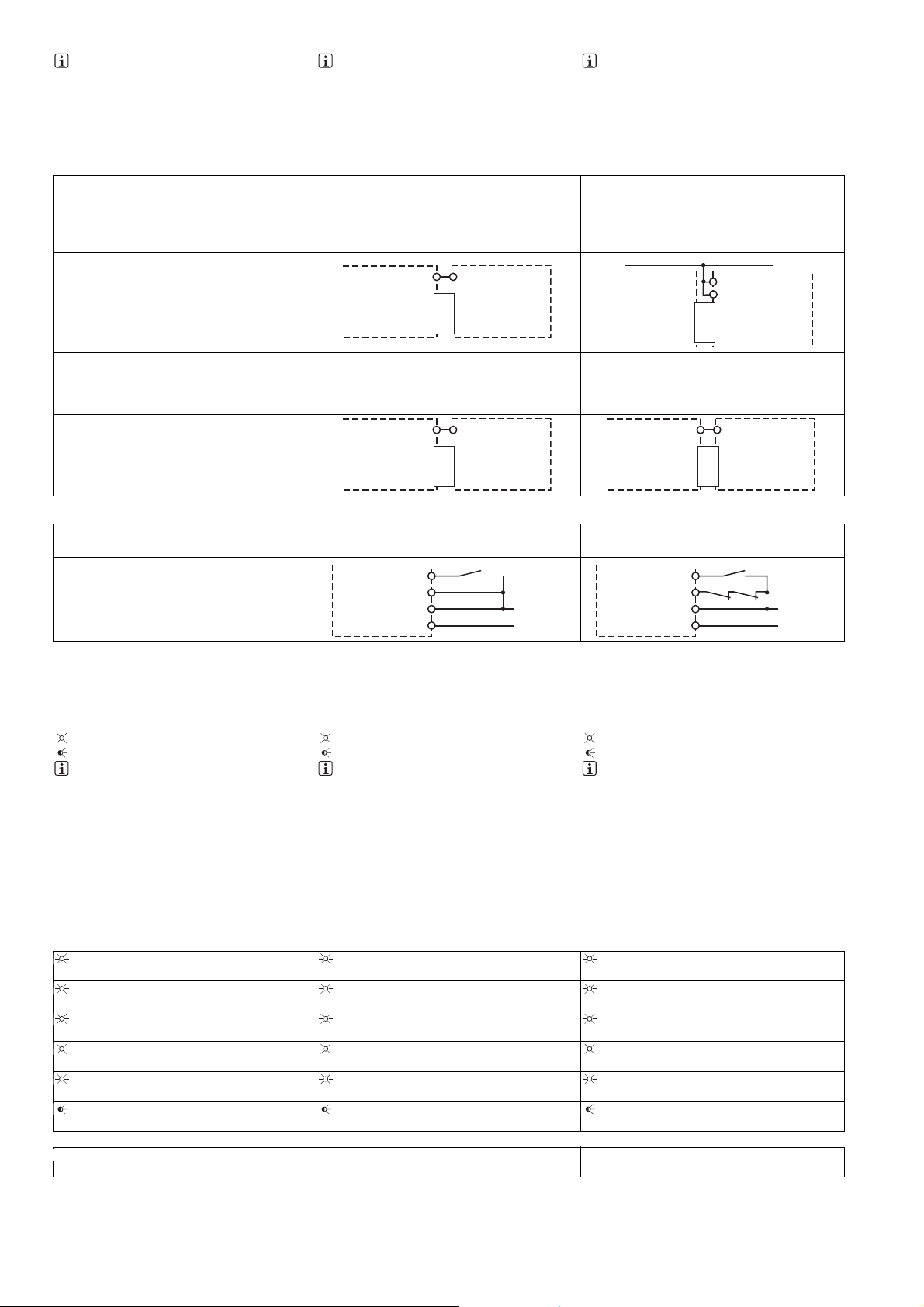
INFO
zum Anschluss "Rückführkreis" mit Grundgeräten PNOZ X oder PNOZelog:
Y1, Y2 und Input sind Eingänge des Grundgeräts, die den Rückführkreis auswerten
INFORMATION
To connect the "feedback loop" to PNOZ X
or PNOZelog base units:
Y1, Y2 and Input are inputs on the base
unit; they evaluate the feedback loop
INFORMATION
pour le raccordement de la « boucle de
retour » avec des appareils de base PNOZ
X ou PNOZelog :
Y1, Y2 et Input sont les entrées de l'appareil de base qui permettent d'analyser la
boucle de retour
` Grundgerät PNOZsigma ` PNOZsigma base unit ` Appareil de base PNOZsigma
Der Eingangskreis wird über den Verbindungsstecker eingebunden und ausgewertet/ The input curcuit is connected and evaluated via the
connector/ Le circuit d'entrée est relié et analysé par le connecteur
Der Eingangskreis wird über den Verbindungsstecker eingebunden und ausgewertet/ The input curcuit is connected and evaluated via the
connector/ Le circuit d'entrée est relié et analysé par le connecteur
Grundgerät: Sicherheitsschaltgeräte PNOZ
s3, PNOZ s4, PNOZ s5/ Base units: safety relays PNOZ s3, PNOZ s4, PNOZ s5/ Appareil de
base : bloc logiques de sécurité PNOZ s3,
PNOZ s4, PNOZ s5
PNOZ s3
PNOZ s4
PNOZ s5
S11
Interface
PNOZsigma
S34
PNOZ s9
Grundgerät: Zweihandbediengerät PNOZ s6/
Base unit: Two-hand control device PNOZ s6/
Appareil de base : relais de commande bimanuelle PNOZ s6
S12
PNOZ s6
Interface
PNOZsigma
S34
PNOZ s9
Grundgerät: Sicherheitsschaltgeräte PNOZ
s1, PNOZ s2/ Base units: safety relays PNOZ
s1, PNOZ s2/ Appareil de base : bloc logiques
de sécurité PNOZ s1, PNOZ s2
A1
S34
PNOZ s1
PNOZ s2
Interface
PNOZsigma
Grundgerät: Zweihandbediengerät PNOZ
s6.1/ Base unit: Two-hand control device
PNOZ s6.1/ Appareil de base : relais de commande bimanuelle PNOZ s6.1
S24
PNOZ s6.1
Interface
PNOZsigma
S34
` Applikation ` Application ` Application
ohne Grundgerät/ without base unit/ sans appareil de base
ohne Rückführkreis/ without feedback loop/
sans boucle de retour
PNOZs9
S32
S34
A1
A2
S3
24 V DC
0 V
mit Rückführkreis/ with feedback loop/ avec
boucle de retour
PNOZs9
S32
S34
A1
A2
K5
K6
24 V DC
PNOZ s9
PNOZ s9
S3
24 V DC
0 V
Betrieb
Das Gerät ist betriebsbereit, wenn die LED Power permanent leuchtet.
LEDs zeigen den Status und Fehler während
des Betriebs an:
LED leuchtet
LED blinkt
INFO
Statusanzeigen und Fehleranzeigen können unabhängig voneinander auftreten. Bei
einer Fehleranzeige leuchtet oder blinkt die
LED "Fault" (Ausnahme: "Versorgungsspannung zu gering"). Eine zusätzlich blinkende LED weist auf eine mögliche
Fehlerursache hin. Eine zusätzlich statisch
leuchtende LED weist auf einen normalen
Betriebszustand hin. Es können mehrere
Statusanzeigen und Fehleranzeigen gleichzeitig auftreten.
Operation
The unit is ready for operation when the Power
LED is permanently lit.
LEDs indicate the status and errors during operation:
LED on
LED flashes
INFORMATION
Status indicators and error indicators may
occur independently. In the case of an error
display, the "Fault" LED will light or flash
(exception: "Supply voltage too low"). An
LED that is also flashing indicates the potential cause of the error. An LED that is lit
and is static indicates a normal operating
status. Several status indicators and error
indicators may occur simultaneously.
Utilisation
L'appareil est prêt à fonctionner lorsque la LED
Power reste allumée en permanence.
Les LEDs indiquent l'état et les erreurs lors du
fonctionnement:
LED allumée
LED clignotante
INFORMATION
L'affichage de l'état et des erreurs peut survenir indépendamment. Lors de l'affichage
d'une erreur, la LED "Fault" s'allume ou clignote (exception : "Tension d'alimentation
trop faible"). Une LED clignotante supplémentaire informe sur une cause possible
d'erreur. Une LED supplémentaire qui s'allume de façon permanente informe de l'état
normal de fonctionnement. Plusieurs affichages de l'état et des erreurs peuvent survenir en même temps.
Statusanzeigen Status indicators Affichages de l'état
Power
Versorgungsspannung liegt an.
In1
Eingangskreis an S32 ist geschlossen.
In2
Eingangskreis an S32 ist geschlossen.
Out
Sicherheitskontakte sind geschlossen.
Reset
An S34 liegt 24 V DC an.
Out
Eingestellte Verzögerungszeit läuft.
Power
Supply voltage is present.
In1
Input circuit at S32 is closed.
In2
Input circuit at S32 is closed.
Out
Safety contacts are closed.
Reset
24 VDC is present at S34.
Out
Set delay time is running.
Power
la tension d'alimentation est présente.
In1
Le circuit d'entrée S32 est fermé.
In2
Le circuit d'entrée S32 est fermé.
Out
Les contacts de sécurité sont fermés.
Réarmement
24 V DC sur S34.
Out
La temporisation réglée fonctionne.
Fehleranzeigen Fault indicators Affichage des erreurs
Alle LEDs aus
Gerät ausgeschaltet.
All LEDs off
Unit switched off.
Toutes les LEDs sont éteintes
Appareil éteint.
- 6 -

Fault
Diagnose: Abschlussstecker nicht gesteckt
` Abhilfe: Abschlussstecker stecken, Ver-
sorgungsspannung aus- und wieder ein-
schalten.
Mit Grundgerät PNOZsigma:
Diagnose: Eingangskreis S32 ist unerlaubt
geschlossen
Fault
Diagnostics: Plug terminator not connected
` Remedy: Insert plug terminator, switch
supply voltage off and then on again.
With PNOZsigma base unit:
Diagnostics: Input circuit S32 is closed
without authorisation
Fault
Diagnostic : fiche de terminaison non branchée
` Solution : Brancher la fiche de terminai-
son, couper puis remettre en marche la
tension d'alimentation.
Avec appareil de base PNOZsigma :
Diagnostic : Le circuit d'entrée S32 est fermé sans autorisation.
Fault
Diagnose: Interner Fehler, Gerät defekt
` Abhilfe: Versorgungsspannung aus- und
wieder einschalten, gegebenenfalls Gerät tauschen.
Power
Diagnose: Versorgungsspannung zu gering
` Abhilfe: Versorgungsspannung überprü-
fen.
Reset
Fault
Diagnose: Unerlaubte Stellung eines Drehschalters oder ein Drehschalter wurde während des Betriebs verstellt.
` Abhilfe: Versorgungsspannung aus- und
wieder einschalten.
Power, In1, In2, Out, Reset, Fault
Diagnose: Der Betriebsartenwahlschalter
"mode" steht in Grundstellung (senkrechte
Position)
` Abhilfe: Versorgungsspannung aus-
schalten und am Betriebsartenwahlschalter "mode" gewünschte Betriebsart
einstellen.
Fehler - Störungen
`
Fehlfunktionen der Kontakte: Bei verschweißten Kontakten ist nach Öffnen des
Eingangskreises keine neue Aktivierung
möglich.
Technische Daten Technical details Caractéristiques techniques
Fault
Diagnostics: Internal error, unit defective
` Remedy: Switch supply voltage off and
then on again, change unit if necessary.
Power
Diagnostics: Supply voltage too low
` Remedy: Check the supply voltage.
Reset
Fault
Diagnostics: Position of rotary switch is not
permitted or rotary switch was adjusted
during operation.
` Remedy: Switch supply voltage off and
then on again.
Power, In1, In2, Out, Reset, Fault
Diagnostics: The operating mode selector
switch "mode" is in its start position (vertical position)
` Remedy: Switch off the supply voltage
and set the required operating mode on
operating mode selector switch "mode".
Faults - malfunctions
`
Contact malfunctions: If the contacts have
welded, reactivation will not be possible after
the input circuit has opened.
Fault
Diagnostic : erreur interne, appareil défectueux
` Remède : couper puis remettre en mar-
Power
Diagnostic : tension d'alimentation trop faible
` Remède : vérifier la tension d'alimenta-
Réarmement
Fault
Diagnostic : sélecteur rotatif dans une position incorrecte ou un sélecteur rotatif à été
déréglé durant le fonctionnement.
` Remède : couper puis remettre en mar-
Power, In1, In2, Out, Reset, Fault
Diagnostic : le sélecteur de mode de marche « mode » est positionné sur la position
de base (position verticale)
` Remède : coupez la tension d'alimenta-
Erreurs – Défaillances
`
Défaut de fonctionnement des contacts de
sortie : si les contacts sont soudés, un réarmement est impossible après ouverture du
circuit d'entrée.
che la tension d'alimentation, si besoin
échanger l'appareil
tion
che la tension d'alimentation.
tion et régler le mode de fonctionnement
souhaité sur le sélecteur de mode de
marche « mode ».
Elektrische Daten Electrical data Données électriques
Versorgungsspannung Supply voltage Tension d'alimentation
Versorgungsspannung U
Spannungstoleranz Voltage tolerance Plage de la tension d'alimentation -20 %/+20 %
Leistungsaufnahme bei U
Restwelligkeit DC Residual ripple DC Ondulation résiduelle DC 20 %
Versorgungsstrom an A1 typ. Typ. supply current at A1 Courant d'alimentation sur A1 env. 70 mA
Spannung und Strom an Voltage and current at Tension et courant sur
Eingangskreis DC: Input circuit DC: circuit d'entrée DC : 15,0 mA
Rückführkreis DC: 24,0 V Feedback loop DC: 24,0 V boucle de retour DC : 24,0 V 15,0 mA
Max. Stromimpuls Max. current pulse Impulsion max. du courant
A1 A1 A1 0,70 A
Eingangskreis Input circuit Circuit d'entrée 0,10 A
Rückführkreis Feedback loop Boucle de retour 0,10 A
Anzahl der Ausgangskontakte Number of output contacts Nombre de contacts de sortie
Sicherheitskontakte (S) verzögert: Safety contacts (N/O), delayed: Contacts de sécurité (F) temporisés
Hilfskontakte (Ö) verzögert: Auxiliary contacts (N/C), delayed: Contacts d'information (O) tempori-
Kategorie der Ausgangskontakte
nach prEN ISO 13849.1
Verzögerungszeit <30 s Delay time <30 s Temporisation <30 s 4
Verzögerungszeit >30 s Delay time >30 s Temporisation >30 s 4
DC Supply voltage UB DC Tension d'alimentation UBDC 24 V
B
DC Power consumption at UB DC Consommation UBDC 2,0 W
B
:
sés :
Category of output contacts in accordance with prEN ISO 13849.1
Catégorie des contacts de sortie
selon prEN ISO 13849.1
3
1
- 7 -

Elektrische Daten Electrical data Données électriques
Gebrauchskategorie nach
EN 60947-4-1
Sicherheitskontakte: AC1 bei 240 V Safety contacts: AC1 at 240 V Contacts de sécurité : AC1
Sicherheitskontakte: DC1 bei 24 V Safety contacts: DC1 at 24 V Contacts de sécurité : DC1 pour
Hilfskontakte: AC1 bei 240 V Auxiliary contacts: AC1 at 240 V Contacts d'information : AC1
Hilfskontakte: DC1 bei 24 V Auxiliary contacts: DC1 at 24 V Contacts d'information : DC1
Gebrauchskategorie nach
EN 60947-5-1
Sicherheitskontakte: AC15 bei
230 V
Sicherheitskontakte: DC13 bei 24 V
(6 Schaltspiele/min)
Hilfskontakte: AC15 bei 230 V Auxiliary contacts: AC15 at 230 V Contacts d'information : AC15
Hilfskontakte: DC13 bei 24 V (6
Schaltspiele/min)
Utilisation category in accordance
with EN 60947-4-1
Catégorie d'utilisation selon
EN 60947-4-1
pour 240 V
24 V
pour 240 V
pour 24 V
Utilisation category in accordance
with EN 60947-5-1
Catégorie d'utilisation selon
EN 60947-5-1
Safety contacts: AC15 at 230 V Contacts de sécurité : AC15
pour 230 V
Safety contacts: DC13 at 24 V (6
cycles/min)
Contacts de sécurité : DC13
pour 24 V (6 manœuvres/min)
pour 230 V
Auxiliary contacts: DC13 at 24 V (6
cycles/min)
Contacts d'information : DC13
pour 24 V (6 manœuvres/min)
I
: 0,01 A , I
min
P
: 2000 VA
max
I
: 0,01 A , I
min
P
: 200 W
max
I
: 0,01 A , I
min
P
: 2000 VA
max
I
: 0,01 A , I
min
P
: 200 W
max
I
: 6,0 A
max
I
: 5,0 A
max
I
: 6,0 A
max
I
: 5,0 A
max
max
max
max
max
: 8,0 A
: 8,0 A
: 8,0 A
: 8,0 A
Kontaktmaterial Contact material Matériau des contacts AgCuNi + 0,2 µm Au
Kontaktabsicherung, extern (I
kA) nach EN 60947-5-1
= 1
External contact fuse protection (I
K
= 1 kA) to EN 60947-5-1
Protection des contacts en externe
K
= 1 kA) selon EN 60947-5-1
(I
K
Schmelzsicherung flink Blow-out fuse, quick Fusible rapide
Sicherheitskontakte: Safety contacts: Contacts de sécurité : 10 A
Hilfskontakte: Auxiliary contacts: Contacts d'information : 10 A
Schmelzsicherung träge Blow-out fuse, slow Fusible normal
Sicherheitskontakte: Safety contacts: Contacts de sécurité : 6 A
Hilfskontakte: Auxiliary contacts: Contacts d'information : 6 A
Sicherungsautomat 24V AC/DC,
Charakteristik B/C
Circuit breaker 24 VAC/DC, characteristic B/C
Disjoncteur 24 V AC/DC, caractéristique B/C
Sicherheitskontakte: Safety contacts: Contacts de sécurité : 6 A
Hilfskontakte: Auxiliary contacts: Contacts d'information : 6 A
Max. Gesamtleitungswiderstand R
max
Max. overall cable resistance R
l-
Résistance max. de l'ensemble du
lmax
câblage R
lmax
A1/A2 A1/A2 A1/A2 20 Ohm
Eingangskreis Input circuit Circuit d'entrée 30 Ohm
Rückführkreis Feedback loop Boucle de retour 30 Ohm
Sicherheitstechnische Kenndaten
Wahrscheinlichkeit eines gefahrbringenden Ausfalls pro Stunde
)
(PFH
D
Sicherheitskontakte verzögert
<30 s
Sicherheitskontakte verzögert
>30 s
Safety-related characteristic
data
Probability of dangerous failure per
hour (PFH
)
D
Caractéristiques techniques de
sécurité
Probabilité d'apparition d'une défaillance dangereuse par heure
)
(PFH
D
Safety contacts, delayed <30 s Contacts de sécurité temporisés
<30 s
Safety contacts, delayed >30 s Contacts de sécurité temporisés
>30 s
2,14E-09 1/h
2,14E-09 1/h
SIL-Anspruchsgrenze (SIL CL) SIL claim limit (SIL CL) Limite de revendication SIL (SIL CL)
Sicherheitskontakte verzögert
<30 s
Sicherheitskontakte verzögert
>30 s
Safety contacts, delayed <30 s Contacts de sécurité temporisés
<30 s
Safety contacts, delayed >30 s Contacts de sécurité temporisés
>30 s
3
3
Performance Level (PL) Performance level (PL) Niveau de performance (PL)
Sicherheitskontakte verzögert
<30 s
Sicherheitskontakte verzögert
>30 s
Proof-Test-Intervall in Jahren Proof test interval in years Intervalle du test périodique en an-
Safety contacts, delayed <30 s Contacts de sécurité temporisés
<30 s
Safety contacts, delayed >30 s Contacts de sécurité temporisés
>30 s
e
e
20
nées
Zeiten Times Temporisations
Einschaltverzögerung Switch-on delay Temps de montée
bei manuellem Start typ. with manual reset typ. pour un réarmement manuel env. 60 ms
bei manuellem Start max. with manual reset max. pour un réarmement manuel max. 80 ms
Rückfallverzögerung Delay-on de-energisation Temps de retombée
bei NOT-AUS typ. with E-STOP typ. sur un arrêt d'urgence env. 40 ms
bei NOT-AUS max. with E-STOP max. sur un arrêt d'urgence max. 50 ms
- 8 -
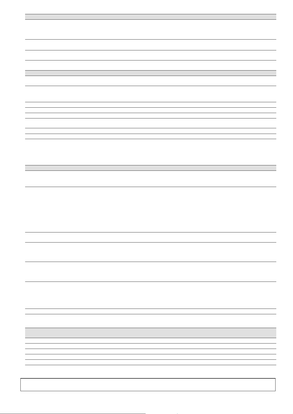
Zeiten Times Temporisations
Wiederbereitschaftszeit bei max.
Schaltfrequenz 1/s
Recovery time at max. switching
frequency 1/s
Temps de réinitialisation pour une
fréquence de commutation max. de
1/s
nach Netzausfall after power failure après une coupure d'alimentation 800 ms
Verzögerungszeit t
: einstellbar Delay time tV: selectable Temporisation tV: réglable
V
Wiederholgenauigkeit Repetition accuracy Précision en reproductibilité -1 %/+1 %, -20 ms/+20 ms
Überbrückung bei Spannungsein-
brüchen der Versorgungsspannung
Überbrückung bei Spannungsein-
brüchen im Eingangskreis
Supply interruption before de-energisation
Supply interruption before de-energisation in the input circuit
Inhibition en cas de micro-coupures
de la tension d'alimentation
Inhibition en cas de micro-coupures
dans le circuit d'entrée
10 ms
10,0 ms
Umweltdaten Environmental data Données sur l'environnement
EMV EMC CEM EN 60947-5-1, EN 61000-6-2,
EN 61000-6-4
Schwingungen nach EN 60068-2-6 Vibration to EN 60068-2-6 Vibrations selon EN 60068-2-6
Frequenz Frequency Fréquence 10 - 55 Hz
Amplitude Amplitude Amplitude 0,35 mm
Klimabeanspruchung Climatic suitability Sollicitations climatiques EN 60068-2-78
Luft- und Kriechstrecken nach Airgap creepage in accordance with Cheminement et claquage selon EN 60947-1
Bemessungsisolationsspannung Rated insulation voltage Tension assignée d'isolement 250 V
Bemessungsstoßspannungsfestig-
keit
Rated impulse withstand voltage Tension assignée de tenue aux
chocs
6,0 kV
Umgebungstemperatur Ambient temperature Température d'utilisation -15 - 55 °C
Lagertemperatur Storage temperature Température de stockage -40 - 85 °C
Schutzart Protection type Indice de protection
Einbauraum (z. B. Schaltschrank) Mounting (e.g. cabinet) Lieu d'implantation (par exemple :
IP54
armoire électrique)
Gehäuse Housing Boîtier IP40
Klemmenbereich Terminals Borniers IP 20
Mechanische Daten Mechanical data Données mécaniques
Gehäusematerial Housing material Matériau du boîtier
Gehäuse Housing Boîtier PC
Front Front Face avant PC
Max. Querschnitt des Außenleiters
bei Schraubklemmen
Max. cross section of external conductors with screw terminals
Capacité de raccordement des borniers à vis
1 Leiter flexibel 1 core flexible 1 câble flexible 0,25 - 2,50 mm² , 24 - 12 AWG
2 Leiter gleichen Querschnitts, flexi-
bel:
mit Aderendhülse, ohne Kunststoff-
hülse
ohne Aderendhülse oder mit TWIN
Aderendhülse
Anzugsdrehmoment bei Schraub-
klemmen
Max. Querschnitt des Außenleiters
bei Käfigzugfederklemmen/Federkraftklemmen: flexibel ohne Aderendhülse
Käfigzugfederklemmen/Federkraftklemmen: Klemmstellen pro Anschluss
2 core, same cross section, flexible: 2 câbles flexibles de même
section :
with crimp connectors, without in-
avec embout, sans cosse plastique 0,25 - 1,00 mm² , 24 - 16 AWG
sulating sleeve
without crimp connectors or with
sans embout ou avec embout TWIN 0,20 - 1,50 mm² , 24 - 16 AWG
TWIN crimp connectors
Torque setting with screw terminals Couple de serrage des borniers à
vis
Max. cross section of external conductors with cage clamp terminals/
spring-loaded terminals: Flexible
Capacité de raccordement des borniers à ressort : flexible sans embout
without crimp connectors
Cage clamp terminals/spring-load-
ed terminals: Terminal points per
Borniers à ressort :points de raccordement pour chaque borne
connection
0,50 Nm
0,20 - 2,50 mm² , 24 - 12 AWG
2
Abisolierlänge Stripping length Longueur dénudation 9 mm
Abmessungen Dimensions Dimensions
Höhe (Schraubklemmen) Height (screw terminals) Hauteur (borniers à vis) 96,0 mm
Höhe (Federkraftklemmen) Height (cage clamp terminals) Hauteur (borniers à ressort) 100,0 mm
Breite Width Largeur 17,5 mm
Tiefe Depth Profondeur 120,0 mm
Gewicht Weight Poids 175 g
Es gelten die 2007-02 aktuellen Ausgaben der
Normen.
Konventioneller thermischer
Conventional thermal current Courant thermique
Strom
The standards current on 2007-02 apply. Les versions actuelles 2007-02 des normes
s'appliquent.
conventionnel
Ith(A) pro Kontakt bei UBDC Ith(A) at UBDC Ith(A) pour UBDC
1 Kontakt 1 contact 1 contact 8,00 A
2 Kontakte 2 contacts 2 contacts 7,00 A
3 Kontakte 3 contacts 3 contacts 6,00 A
21
D.3.E. ELECTRONIQUE - Parc d ’Activité SAVIPOL - B.P. 55 - 10302 SAINTE SAVINE
Téléphone 03.25.71.31.50 - Télécopie 03.25.74.38.82 – Email : electronique@d3e.fr
- 9 -

21 402-01
PNOZ s10
4D Betriebsanleitung
4GB Operating instructions
4F Manuel dutilisation
Sicherheitsschaltgerät PNOZ s10
Das Gerät erfüllt die Forderungen der
EN 60947-5-1, EN 60204-1 und VDE 0113-1.
Der Kontakterweiterungsblock dient als Erweiterungsgerät zu Kontaktverstärkung und
Kontaktvervielfältigung für ein Basisgerät.
Basisgeräte sind alle Sicherheitsschaltgeräte
mit Rückführkreis.
Die zu realisierende Kategorie nach EN 954-1
ist abhängig von der Kategorie des Basisgeräts. Sie kann vom Kontakterweiterungsblock
nicht überschritten werden.
Zu Ihrer Sicherheit
Installieren und nehmen Sie das Gerät nur
`
dann in Betrieb, wenn Sie diese Betriebsanleitung gelesen und verstanden haben
und Sie mit den geltenden Vorschriften
über Arbeitssicherheit und Unfallverhütung vertraut sind.
Beachten Sie die VDE- sowie die örtlichen
Vorschriften, insbesondere hinsichtlich
Schutzmaßnahmen.
` Durch Öffnen des Gehäuses oder eigen-
mächtige Umbauten erlischt jegliche Gewährleistung.
Gerätemerkmale
Relaisausgänge zwangsgeführt:
`
– 4 Sicherheitskontakte (S) unverzögert
– 1 Hilfskontakt (Ö) unverzögert
` Sichere Trennung der Sicherheitskontakte
13-14, 23-24, 33-34, 43-44 von allen anderen Stromkreisen
` LED-Anzeige für:
– Eingangszustand Kanal 1
– Eingangszustand Kanal 2
– Schaltzustand Sicherheitskontakte
–Fehler
` steckbare Anschlussklemmen (wahlweise
Federkraftklemme oder Schraubklemme)
PNOZ s10 safety relay
The unit meets the requirements of
EN 60947-5-1, EN 60204-1 and VDE 0113-1.
The contact expander module is used to increase the number of contacts available for a
base unit. Base units are all safety relays with
a feedback loop.
The category that can be achieved in accordance with EN 954-1 depends on the category
of the base unit. The contact expander module may not exceed this.
For your safety
Only install and commission the unit if you
`
have read and understood these operating instructions and are familiar with the
applicable regulations for health and
safety at work and accident prevention.
Ensure VDE and local regulations are met,
especially those relating to safety.
` Any guarantee is rendered invalid if the
housing is opened or unauthorised modifications are carried out.
Unit features
Positive-guided relay outputs:
`
– 4 safety contacts (N/O), instantaneous
– 1 auxiliary contact (N/C), instantan-
eous
` Safe separation of safety contacts 13-14,
23-24, 33-34, 43-44 from all other circuits
` LED indicator for:
– Input status, channel 1
– Input status, channel 2
– Switch status, safety contacts
–Error
` Plug-in connection terminals (either cage
clamp terminal or screw terminal)
Bloc logique de sécurité PNOZ s10
Cet appareil répond aux exigences des
normes EN 60947-5-1, EN 60204-1 et
VDE 0113-1. Le bloc d'extension de contacts
sert d'appareil d'extension pour augmenter et
multiplier le nombre de contacts d'un appareil de base. Les appareils de base sont tous
des blocs logiques de sécurité dotés d'une
boucle de retour.
La catégorie à réaliser selon la norme
EN 954-1 dépend de la catégorie de l'appareil de base. Elle ne peut pas être dépassée
par le bloc d'extension de contacts.
Pour votre sécurité
Vous n'installerez l'appareil et ne le met-
`
trez en service qu'après avoir lu et compris le présent manuel d'utilisation et vous
être familiarisé avec les prescriptions en
vigueur sur la sécurité du travail et la prévention des accidents.
Respectez la norme VDE ainsi que les
prescriptions locales, particulièrement en
ce qui concerne la sécurité.
` L'ouverture de l'appareil ou sa modifica-
tion rend la garantie automatiquement
caduque.
Caractéristiques de l’appareil
Sorties à relais à contacts liés :
`
– 4 contacts de sécurité (F) instantanés
– 1 contact d'info (O) instantané
` Séparation galvanique entre les contacts
de sécurité 13-14, 23-24, 33-34, 43-44 de
tous les autres circuits
` LED de visualisation pour les états sui-
vants :
– État d'entrée canal 1
– État d'entrée canal 2
– État de commutation des contacts de
sécurité
– Erreur
` Borniers débrochables (au choix avec rac-
cordement à ressort ou à vis)
Sicherheitseigenschaften
Das Schaltgerät erfüllt folgende Sicherheitsanforderungen:
` Der Kontakterweiterungsblock erweitert
einen bestehenden Stromkreis. Da die
Ausgangsrelais durch den Rückführkreis
des Basisgeräts überwacht werden, übertragen sich die Sicherheitsfunktionen des
bestehenden Stromkreises auf den Kontakterweiterungsblock.
` Die Sicherheitseinrichtung bleibt auch bei
Ausfall eines Bauteils wirksam.
` Erdschluss im Rückführkreis:
Wird abhängig vom verwendeten Basisgerät erkannt.
` Erdschluss im Eingangskreis:
Die Ausgangsrelais fallen ab und die Sicherheitskontakte öffnen.
Safety features
The relay meets the following safety requirements:
` The contact expander module expands an
existing circuit. As the output relays are
monitored via the base unit's feedback
loop, the safety functions on the existing
circuit are transferred to the contact expander module.
` The safety function remains effective even
in the case of a component failure.
` Earth fault in the feedback loop:
Detected, depending on the base unit that
is used.
` Earth fault in the input circuit:
The output relays de-energise and the
safety contacts open.
- 1 -
Caractéristiques de sécurité
Le relais satisfait aux exigences de sécurité
suivantes :
` Le bloc d'extension de contacts permet
d'étendre un circuit existant. Comme le
relais de sortie est surveillé par la boucle
de retour de l'appareil de base, les fonctions de sécurité du circuit existant sont
transmises au bloc d'extension de contacts.
` Le dispositif de sécurité reste actif, même
en cas de défaillance d'un composant.
` Mise à la terre dans la boucle de retour :
Est détectée en fonction de l'appareil de
base utilisé.
` Mise à la terre dans le circuit d'entrée :
Les relais de sortie retombent et les contacts de sécurité s'ouvrent.

Blockschaltbild/Klemmenbelegung
Block diagram/terminal configuration
Schéma de principe/affectation des bornes
A1 A2
13
=
Input
=
Power
* Sichere Trennung nach EN 60947-1, 6 kV
Mitte: Frontansicht mit Abdeckung
Rechts: Frontansicht ohne Abdeckung
Funktionsbeschreibung
mit PNOZsigma Basisgerät:
` Zweikanalige Ansteuerung über PNOZsig-
ma Verbindungsstecker
ohne PNOZsigma Basisgerät:
` Einkanalige Ansteuerung: ein Eingangs-
kreis wirkt auf die Ausgangsrelais
Montage
Kontakterweiterungsblock ohne Basisgerät PNOZsigma montieren
` Stellen Sie sicher, dass der Abschluss-
stecker seitlich am Gerät gesteckt ist
Basisgerät und Kontakterweiterungsblock
PNOZsigma verbinden
` Entfernen Sie den Abschlussstecker seit-
lich am Basisgerät und am Kontakterweiterungsblock
` Verbinden Sie das Basisgerät und den
Kontakterweiterungsblock mit dem mitgelieferten Verbindungsstecker bevor Sie die
Geräte auf der Normschiene montieren.
Montage im Schaltschrank
` Montieren Sie das Gerät in einen Schalt-
schrank mit einer Schutzart von mindestens IP54.
` Befestigen Sie das Gerät mit Hilfe des
Rastelements auf der Rückseite auf einer
Normschiene.
` Sichern Sie das Gerät auf einer senkrech-
ten Normschiene (35 mm) durch ein Halteelement (z. B. Endhalter oder Endwinkel).
` Vor dem Abheben der Normschine Gerät
nach oben oder unten schieben
Verdrahtung
Beachten Sie:
` Angaben im Abschnitt „Technische Da-
ten“ unbedingt einhalten.
` Die Ausgänge 13-14, 23-24, 33-34 und
43-44 sind unverzögerte Sicherheitskontakte
` Der Ausgang 51-52 ist ein Hilfskontakt
` Vor die Ausgangskontakte eine Sicherung
(s. techn. Daten) schalten, um das Verschweißen der Kontakte zu verhindern.
K1
K2
14
23 33 51
24 34 52
*
43
unit
base
Interface
44
*Safe separation i.a.w. EN 60947-1, 6 kV
Centre: Front view with cover
Right: Front view without cover
Function description
with PNOZsigma base unit:
` Dual-channel operation via PNOZsigma
connector
without PNOZsigma base unit:
` Single-channel operation: one input circuit
affects the output relays
Installation
Mount expander module without
PNOZsigma base module
` Ensure that the plug terminator is inserted
at the side of the unit.
Connect base unit and PNOZsigma contact expander module
` Remove the plug terminator at the side of
the base unit and at the contact expander
module.
` Connect the base unit and the contact ex-
pander module to the supplied connector
before mounting the units to the DIN rail.
Installation in control cabinet
` The unit should be installed in a control
cabinet with a protection type of at least
IP54.
` Use the notch on the rear of the unit to at-
tach it to a DIN rail.
` Ensure the unit is mounted securely on a
vertical DIN rail (35 mm) by using a fixing
element (e.g. a retaining bracket or an end
angle).
` Push the unit upwards or downwards be-
fore lifting the DIN rail.
Wiring
Please note:
` Information given in the "Technical de-
tails" must be followed.
` Outputs 13-14, 23-24, 33-34 and 43-44
are instantaneous safety contacts.
` Output 51-52 is an auxiliary contact.
` To prevent contact welding, a fuse should
be connected before the output contacts
(see "Technical details").
* Séparation galvanique selon la norme
EN 60947-1, 6 kV
Schéma du milieu : vue frontale avec recouvrement
Schéma de droite : vue frontale sans recouvrement
Descriptif du fonctionnement
avec un appareil de base PNOZsigma :
` Commande à deux canaux par le connec-
teur PNOZsigma
sans appareil de base PNOZsigma :
` Commande monocanale : un circuit d'en-
trée s'applique aux relais de sortie
Montage
Installer le bloc d'extension de contacts
sans appareil de base PNOZsigma
` Assurez-vous que la fiche de terminaison
est branchée sur le côté de l'appareil.
Raccorder l'appareil de base et le bloc
d'extension de contacts PNOZsigma
` Retirez la fiche de terminaison sur le côté
de l'appareil de base et sur le bloc d'ex-
tension de contacts.
` Avant de monter les appareils sur le rail
DIN, reliez l'appareil de base et le bloc
d'extension de contacts à l'aide du con-
necteur fourni.
Montage dans une armoire
` Installez l'appareil dans une armoire ayant
un indice de protection d’au moins IP54.
` Montez l'appareil sur un rail DIN à l'aide
du système de fixation situé au dos de
l'appareil.
` Fixez l'appareil monté sur un rail DIN ver-
tical (35 mm) à l'aide d'un élément de
maintien (par ex. un support terminal ou
une équerre terminale).
` Avant de lever le rail DIN, poussez l'appa-
reil vers le haut ou vers le bas.
Câblage
Important :
` Respectez impérativement les données
indiquées dans la partie "Caractéristiques
techniques".
` Les sorties 13-14, 23-24, 33-34 et 43-44
sont des contacts de sécurité instantanés.
` La sortie 51-52 un contact d'info.
` Protégez les contacts de sortie par des fu-
sibles (voir "Caractéristiques techniques")
pour éviter leur soudage.
- 2 -

` Berechnung der max. Leitungslänge I
im Eingangskreis:
R
lmax
=
Rl / km
= max. Gesamtleitungswiderstand
lmax
R
I
max
max
(s. techn. Daten)
R
/ km = Leitungswiderstand/km
l
` Leitungsmaterial aus Kupferdraht mit ei-
ner Temperaturbeständigkeit von 60/
75 °C verwenden.
` Sorgen Sie an allen Ausgangskontakten
bei kapazitiven und induktiven Lasten für
eine ausreichende Schutzbeschaltung.
` Calculation of the max. cable runs l
the input circuit:
R
lmax
=
Rl / km
= max. overall cable resistance
R
I
max
lmax
max
(see "Technical details")
R
/ km = cable resistance/km
l
` Use copper wire that can withstand 60/
75 °C.
` Sufficient fuse protection must be pro-
vided on all output contacts with capacitive and inductive loads.
` Calcul de la longueur de câble maxi I
in
sur le circuit d'entrée :
R
lmax
=
Rl / km
= résistance de câblage totale maxi
R
I
max
lmax
(voir "Caractéristiques techniques")
R
/ km = Résistance du câble/km
l
` Utilisez des fils de câblage en cuivre sup-
portant des températures de 60/75 °C.
` Assurez-vous du pouvoir de coupure des
contacts de sortie en cas de charges capacitives ou inductives.
max
Betriebsbereitschaft herstellen
Versorgungsspannung
`
Versorgungsspannung/Supply voltage/
Preparing for operation
Supply voltage
`
AC DC
Mise en route
Tension d'alimentation
`
Tension d'alimentation
24 V DC
A1
A2
0 V
` Eingangskreis
` Input circuit
` Circuit d'entrée
Eingangskreis/Input circuit/Circuit d'entrée Einkanalig/Single-channel/Monocanal Zweikanalig/Dual-channel/Bicanal
Basisgerät:
24 V DC
Sicherheitsschaltgerät PNOZ X/
Base unit:
PNOZ X safety relay/
Appareil de base :
Bloc logique de sécurité PNOZ X
0 V
A1
A2
PNOZ s10
Basisgerät:
Sicherheitsschaltgerät PNOZelog
Ansteuerung durch Halbleiterausgänge
(24 V DC)/Base unit:
PNOZelog safety relay
Driven via semiconductor outputs
(24 VDC)/
Appareil de base :
Bloc logique de sécurité PNOZelog
O1
A1
PNOZ s10
A20 V
L-
Commande par sorties statiques (24 V DC)
PNOZ s10
` Rückführkreis
Rückführkreis/Feedback loop/Boucle de
retour
Y1, Y2 und Input sind Eingänge des Basisgeräts, die den Rückführkreis auswerten/
Y1, Y2 and Input are inputs on the base unit;
they evaluate the feedback loop/
Y1, Y2 et Input sont des entrées de l'appareil
de base qui analysent la boucle de retour
` Anschluss an PNOZsigma Basisgerät
Der Rückführkreis wird über den Verbindungsstecker eingebunden und ausgewertet/
The feedback loop is connected and evaluated via the connector/La boucle de retour
est reliée et analysée par le connecteur
` Feedback loop
Basisgerät: Sicherheitsschaltgerät PNOZ/
X/Base unit: PNOZ X safety relay/Appareil
de base : bloc logique de sécurité PNOZ X
` Boucle de retour
Basisgerät: Sicherheitsschaltgerät
PNOZelog/Base unit: PNOZelog safety relay/Appareil de base : bloc logique de sécurité PNOZelog
24 V DC
Y1
Y2
` Connection to PNOZsigma base unit
51
52
PNOZ s10
51
Input
52
PNOZ s10
` Raccordement à l'appareil de base
PNOZsigma
Basisgerät: Sicherheitsschaltgerät PNOZsigma/Base unit: PNOZsigma safety relay/
Appareil de base : bloc logique de sécurité PNOZsigma
PNOZsigma
base unit
Interface
PNOZsigma
PNOZ s10
- 3 -

Betrieb
LEDs zeigen den Status und Fehler während
des Betriebs an:
Run
LEDs indicate the status and errors during
operation:
Fonctionnement
Les LED indiquent l'état et les erreurs lors du
fonctionnement :
LED leuchtet
Statusanzeigen
Zustand/Status/État
In1
In2
Out
Fault
Kanal 1 angesteuert/Channel 1 actuated/Canal 1 activé
Kanal 2 angesteuert/Channel 2 actuated/Canal 2 activé
Sicherheitskontakte sind geschlossen/Safety contacts are closed/Contacts de sécurité fermés
Fehleranzeigen
Power
In1
In2
Out
Reset
INFO
Wenn ein Basisgerät und ein Erweiterungsgerät der Produktfamilie
PNOZsigma über den Verbindungsstekker verbunden sind, ist keine weitere
Verdrahtung notwendig.
A1 am Erweiterungsgerät nicht anschließen!
LED on
Status indicators
Error indicators
Diagnose/Diagnostics/Diagnostic Abhilfe/Remedy/Remède
Fault
Abschlussstecker nicht gesteckt/Plug terminator not connected/Fiche de terminaison pas branchée
INFORMATION
If a PNOZsigma base unit and an expander module are connected via the
connector, no additional wiring is necessary.
Do not connect A1 to the expander
module!
LED allumée
Affichages d’état
Affichage des erreurs
Abschlussstecker stecken, Spannungsreset/Connect plug terminator, voltage
reset/Branchez la fiche de terminaison,
coupez et remettez l'appareil sous tension
INFORMATION
Lorsqu'un appareil de base et un appareil d'extension de la gamme
PNOZsigma sont liés par le biais d'un
connecteur, aucun câblage supplémentaire n'est nécessaire.
Ne raccordez pas A1 à l'appareil d'extension !
Fehler - Störungen
Kurzschluss am Eingangskreis:
`
Die Versorgungsspannung bricht zusammen und die Sicherheitskontakte werden
über eine elektronische Sicherung geöffnet. Nach Wegfall der Störungsursache
und Abschalten der Versorgungsspannung für ca. 1 Minute ist das Gerät wieder
betriebsbereit.
` Fehlfunktionen der Kontakte: Bei ver-
schweißten Kontakten ist nach Öffnen des
Eingangskreises keinen neue Aktivierung
möglich.
Technische Daten Technical details Caractéristiques techniques
Elektrische Daten Electrical data Données électriques
Versorgungsspannung U
Spannungstoleranz Voltage tolerance Plage de la tension d’alimentation -20 % ... +20 %
Leistungsaufnahme bei U
Restwelligkeit DC Residual ripple DC Ondulation résiduelle DC 20 %
Spannung und Strom an
Eingangskreis: 24,0 V DC
Ausgangskontakte nach EN 954-1,
Kategorie 4
Sicherheitskontakte (S): Safety contacts (N/O): Contacts de sécurité (F) : 4
Hilfskontakte (Ö): Auxiliary contacts (N/C): Contacts d'info (O) : 1
DC Supply voltage UB DC Tension d'alimentation UBDC 24 V
B
DC Power consumption at UBDC Consommation pour UB DC 3 W
B
Voltage and current at
Input circuit: 24.0 VDC
Output contacts in accordance with
EN 954-1, Category 4
Faults - malfunctions
Short circuit in the input circuit:
`
The supply voltage fails and the safety
contacts open via an electronic fuse.
Once the cause of the respective fault has
been rectified and the supply voltage is
switched off for approx. 1 minute, the unit
is ready for operation again.
` Contact malfunction: If the contacts have
welded, reactivation will not be possible
after the input circuit has opened.
Tension et courant
Circuit d'entrée : 24,0 V DC 95 mA
Contacts de sortie selon la norme
EN 954-1, catégorie 4
Erreurs - Défaillances
Court-circuit dans le circuit d'entrée :
`
La tension d'alimentation chute et les contacts de sécurité sont ouverts par un fusible électronique. Une fois la cause du
défaut éliminée et la tension d'alimentation coupée, l'appareil est de nouveau
prêt à fonctionner au bout d'une minute
environ.
` Défaut de fonctionnement des contacts
de sortie : si les contacts sont soudés,
aucune activation n'est possible après
l'ouverture du circuit d'entrée.
- 4 -

Technische Daten Technical details Caractéristiques techniques
Gebrauchskategorie nach
EN 60947-4-1
Sicherheitskontakte: AC1: 240 V
Sicherheitskontakte: DC1: 24 V
Hilfskontakte: AC1: 240 V
Hilfskontakte: DC1: 24 V
Gebrauchskategorie nach
EN 60947-5-1
Sicherheitskontakte: AC15: 230 V
Sicherheitskontakte: DC13
(6 Schaltspiele/min): 24 V
Hilfskontakte: AC15: 230 V
Hilfskontakte: DC13
(6 Schaltspiele/min): 24 V
Utilisation category i.a.w.
EN 60947-4-1
Safety contacts: AC1: 240 V
Safety contacts: DC1: 24 V
Auxiliary contacts: AC1: 240 V
Auxiliary contacts: DC1: 24 V
Utilisation category i.a.w.
EN 60947-5-1
Safety contacts: AC15: 230 V
Safety contacts: DC13:
(6 cycles/min): 24 V
Auxiliary contacts: AC15: 230 V
Auxiliary contacts: DC13:
(6 cycles/min): 24 V
Catégorie d'utilisation selon la norme
EN 60947-4-1
Contacts de sécurité : AC1 : 240 V
Contacts de sécurité : DC1 : 24 V
Contacts d'info : AC1 : 240 V
Contacts d'info : DC1 : 24 V
Catégorie d'utilisation selon la norme
EN 60947-5-1
Contacts de sécurité : AC15 : 230 V
Contacts de sécurité : DC13
(6 manœuvres/min) : 24 V
Contacts d'info : AC15 : 230 V
Contacts d'info : DC13
(6 manœuvres/min) : 24 V
: 0,01 A, I
I
min
P
max
I
: 0,01 A, I
min
P
max
I
: 0,01 A, I
min
P
max
: 0,01 A, I
I
min
P
max
I
: 6,0 A
max
: 7,5 A
I
max
I
: 3,0 A
max
: 3,5 A
I
max
: 3000 VA
: 300 W
: 1500 VA
: 150 W
max
max
max
max
: 12,0 A
: 12,0 A
: 6,0 A
: 6,0 A
Kontaktmaterial Contact material Matériau des contacts AgSnO2 + 0,2 µm Au
Kontaktabsicherung, extern
(EN 60947-5-1) I
Schmelzsicherung flink
= 1kA
K
Sicherheitskontakte:
Hilfskontakte:
Schmelzsicherung träge:
Sicherheitskontakte:
Hilfskontakte:
Sicherungsautomat 24 V AC/DC,
Charakteristik B/C
Sicherheitskontakte:
Hilfskontakte:
Max. Gesamtleitungswiderstand
Eingangskreise,
R
lmax
Startkreise
einkanalig bei U
B
DC
Sicherheitstechnische Kenndaten
Wahrscheinlichkeit eines gefahrbringenden Ausfalls pro Stunde
)
(PFH
D
External contact fuse protection
(EN 60947-5-1) I
Blow-out fuse, quick
= 1 kA
K
Safety contacts:
Auxiliary contacts:
Blow-out fuse, slow:
Safety contacts:
Auxiliary contacts:
Circuit breaker, 24 VAC/DC, characteristic B/C
Safety contacts:
Auxiliary contacts:
Max. overall cable resistance R
Input circuits,
lmax
reset circuits
Single-channel at U
B
DC
Safety-related characteristic
data
Probability of a dangerous failure
per hour (PFH
)
D
Protection des contacts, externe
(EN 60947-5-1) I
Fusible rapide
= 1 kA
K
Contacts de sécurité :
Contacts d'info :
Fusible normal :
Contacts de sécurité :
Contacts d'info :
Disjoncteur 24 V AC/DC, caractéristique B/C
Contacts de sécurité :
Contacts d'info :
Résistance de câblage totale maxi
R
circuits d'entrée,
lmax
circuits de réarmement
à un canal pour U
DC 30 Ohm
B
Caractéristiques techniques de
sécurité
Probabilité de défaillance dangereuse par heure (PFHD)
16 A
6 A
10 A
4 A
10 A
4 A
2,31*10
-9
SIL-Anspruchsgrenze (SIL CL) SIL limit (SIL CL) Niveau SIL (SIL CL) 3
Performance Level (PL) Performance level (PL) Niveau de performance (PL) e
Proof-Test-Intervall in Jahren Proof test interval in years Intervalle du test périodique en
20
années
Zeiten Times Temps
Rückfallverzögerung
bei NOT-AUS typ.
bei NOT-AUS max.
bei Netzausfall typ.
bei Netzausfall max.
Einschaltverzögerung
Delay-on de-energisation
With E-STOP typ.
With E-STOP max.
With power failure typ.
With power failure max.
Switch-On Delay
Temporisation à la retombée
en cas d'ARRÊT D'URGENCE, typ.
en cas d'ARRÊT D'URGENCE, maxi
en cas de panne de secteur, typ.
en cas de panne de secteur, maxi
Temporisation d'enclenchement
20 ms
30 ms
20 ms
30 ms
en cas de réarmement automati-
bei automatischem Start typ.
With automatic reset typ.
que, typique
30 ms
en cas de réarmement automati-
bei automatischem Start max.
With automatic reset max.
que, maxi
50 ms
Umweltdaten Environmental data Environnement
EMV EMC CEM EN 60947-5-1, EN 61000-6-2,
61000-6-4
Schwingungen nach EN 60068-2-6
Frequenz
Amplitude
Vibration in accordance with
EN 60068-2-6
Frequency
Amplitude
Vibrations selon la norme
EN 60068-2-6
Fréquence
Amplitude
10 - 55 Hz
0,35 mm
Klimabeanspruchung Climatic suitability Sollicitations climatiques EN 60068-2-78
Luft- und Kriechstrecken Airgap creepage Cheminement et claquage EN 60947-1
Bemessungsisolationsspannung Rated insulation voltage Tension d'isolement assignée 250 V
Bemessungsstoßfestigkeit Rated impulse strength Résistance aux chocs assignée 6 kV
Umgebungstemperatur Ambient temperature Température d'utilisation -10 - +55 °C
Lagertemperatur Storage temperature Température de stockage -40 - +85 °C
Schutzart
Einbauraum (z. B. Schaltschrank)
Gehäuse
Klemmenbereich
Protection type
Mounting (e.g. cabinet)
Housing
Te rm i na ls
Indice de protection
Lieu d'implantation (p. ex. armoire)
Boîtier
Borniers
IP 54
IP 40
IP 20
Mechanische Daten Mechanical data Données mécaniques
Gehäusematerial
Gehäuse
Front
Housing material
Housing
Front
Matériau du boîtier
Boîtier
Face avant
PC
PC
- 5 -

Technische Daten Technical details Caractéristiques techniques
Max. Querschnitt des Außenleiters
bei Schraubklemmen
1 Leiter flexibel
2 Leiter gleichen Querschnitts, flexibel:
mit Aderendhülse, ohne Kunststoffhülse
ohne Aderendhülse oder mit TWIN
Aderendhülse
Anzugsdrehmoment bei Schraubklemmen
Max. Querschnitt des Außenleiters
bei Federkraftklemmen
flexibel ohne Aderendhülse
Federkraftklemmen
Klemmstellen pro Anschluss
Abisolierlänge
Abmessungen (H x B x T)
mit Schraubklemmen
mit Federkraftklemmen
Max. cross section of external conductor with screw terminals
1 core flexible
2 core, same cross section, flexible:
Section maxi du conducteur
externe pour les borniers à vis
1 conducteur souple
2 conducteurs de même section,
souples :
with crimp connectors, without in-
avec embout, sans cosse plastique
sulating sleeve
without crimp connectors or with
sans embout ou avec embout TWIN
TWIN crimp connectors
Torque setting with screw terminals Couple de serrage pour les borniers
à vis 0,50 Nm
Max. cross section of external con-
ductor with screw terminals
Flexible without crimp connectors
Spring-loaded terminals
Terminal points per connection
Stripping length
Dimensions (H x W x D)
With screw terminals
With spring-loaded terminals
Section maxi du conducteur
externe pour les borniers à vis
souple sans embout
Borniers à ressort
Nombre de bornes par raccord
Longueur dénudée
Dimensions (H x l x P)
avec borniers à vis
avec borniers à ressort
0,25 - 2,50 mm
0,25 - 1,00 mm
0,20 - 1,50 mm
0,2 - 2,5 mm
2
9 mm
98 mm x 45,0 mm x 120 mm
102 mm x 45,0 mm x 120 mm
Gewicht Weight Poids 300 g
2
, 24 - 12 AWG
2
, 24 - 12 AWG
2
, 24 - 12 AWG
2
Es gelten die 2006-04 aktuellen Ausgaben
der Normen.
Konventioneller thermischer
Strom bei gleichzeitiger Bela-
Conventional thermal current
while loading several contacts
stung mehrerer Kontakte
The standard versions current on 2006/04
apply.
Courant thermique convention-
nel en cas de charge simultanée
de plusieurs contacts
Les versions actuelles 2006-04 des normes
s'appliquent.
Anzahl der Kontakte Number of contacts Nombre de contacts Ith (A) pro Kontakt/per contact/
par contact
11112,00 A
22211,00 A
3339,00 A
4448,00 A
D.3.E. ELECTRONIQUE - Parc d ’Activité SAVIPOL - B.P. 55 - 10302 SAINTE SAVINE
Téléphone 03.25.71.31.50 - Télécopie 03.25.74.38.82 – Email : electronique@d3e.fr
- 6 -
 Loading...