

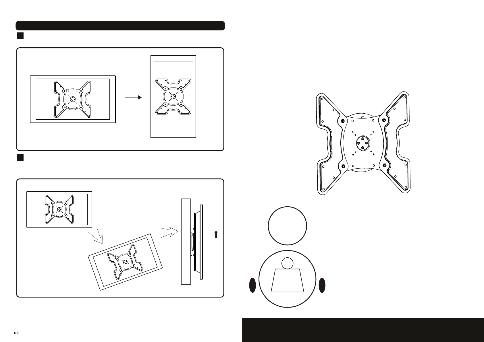
Angle Adjustment
5
Firmly hold two edges of th e disp lay and turn it into the desir ed ang le.the pit ching angle can be ad justed in
a posi tion of 0°,90°,180° and 270°as shown in fig.4.1 .
Remov ing Display
6
To remo ve th e dis pla y fro m mou nt,turn the dis pla y int o an in cli ned position. and t hen l ift t he di spl ay off as
shown in fig.5.1.
Note: Make sure the rotation a ngl e of di spl ay is n ot in a hori zon tal and ve rtical positi on, b ut in a n inc lin ed
position.
INSTALLATION INSTRUCTIONS
fig.5.1
wall
fig. 6.1
Maintenance
• Once you hav e moun ted th e brac ket an d the flat screen, check that they are su ffic iently secure d and safely to
use. You should check wheth er scr ews ar e fixe d well every two months.
• If you have any doubts regardi ng the insta llation , plea se con sult our ret ailer or ser vice departme nt for detail.
7
Rotate: 360°
50kg
(110lbs)
MAX
Fixed Wall Mount
Model: LP12-44F
Max Loa d Cap aci ty : 50k g(11 0lbs)
NOTE: Read entire instruction sheet before you start installation and assembly.
WARNING
• Do not begin the installation of the product before you have read and understood the
instructions and warnings contained in this installation sheet. If you have any question
regarding any of the instruction or warning, Please contact your local distributor.
• Please refer to the installation guide recommendation for required distance from wall
to avoid risk of property damage.
• This product should only be installed by someone of good mechanical aptitude, with
experience and basic building, and fully understands.
• Make sure that the supporting surface will safely support the combined load of the
equipment and all attached hardware and components.
• Never exceed the maximum load capacity.
• If mounting to wood wall studs, make sure that mounting screws are anchored into
the center of the studs. Use of an “edge to edge” stud finder is highly recommended.
• Always use an assistant or mechanical lifting equipment to safely lift and position
equipment.
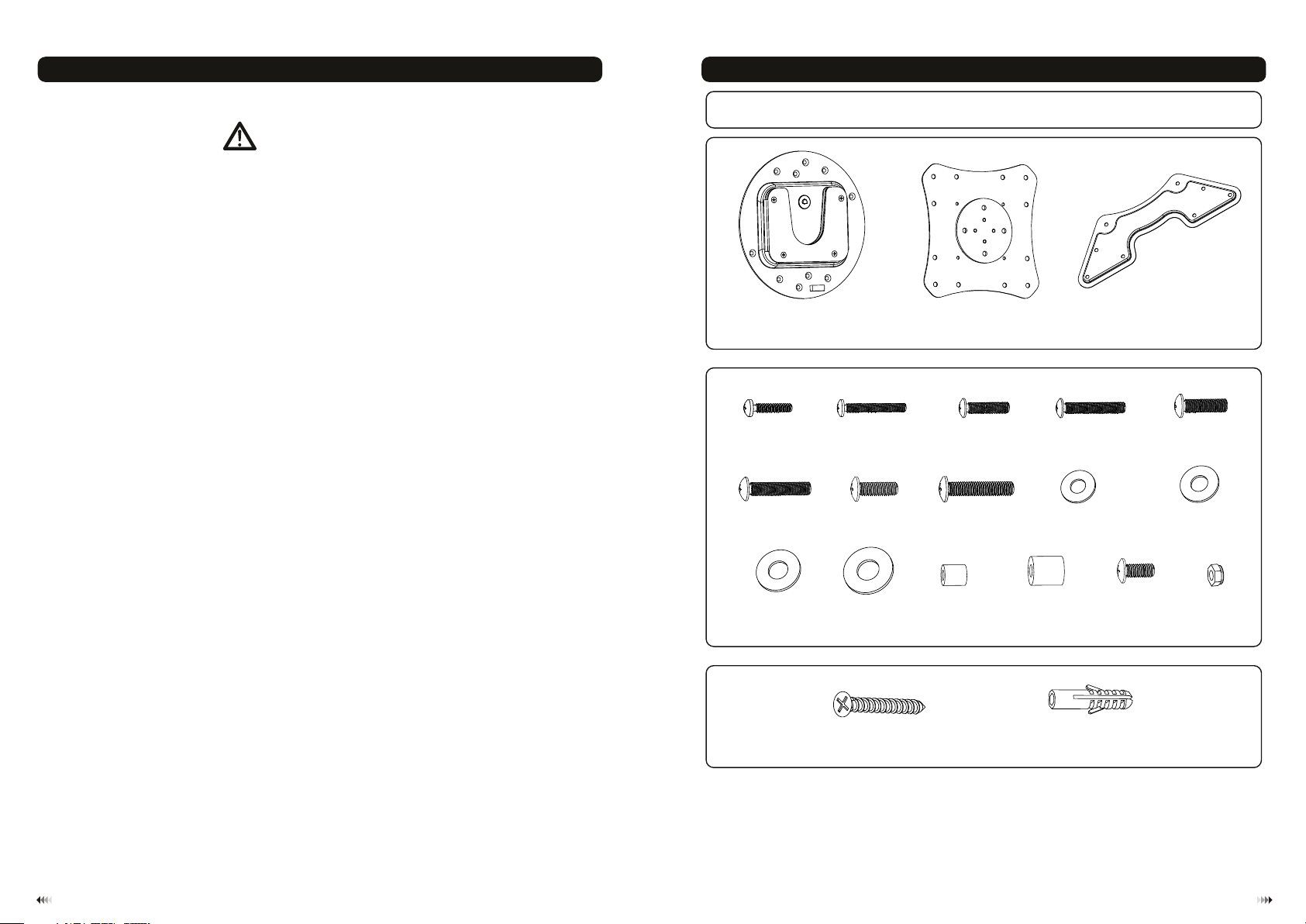
Component Checklist
IMPORTANT: Ens ure y ou h ave r ece ived al l par ts agai nst t he comp one nt chec kli st prio r to in sta ll ing . If an y pa rts
are m is sin g or fa ul ty, te lep hon e the spe cia l franc his er for a re pla cemen t.
wall pl at e A(x1)
adapt er p late B(x1)
adapt er b racke t C(x2)
Package M
M4x10
M-A
M6x20
M-F
(x4)
(x4)
M4x20 ( x4 )
M-B
M8x15 ( x4 )
M-G
M5x10 ( x4 )
M-C
M8x30 ( x4 )
M-H
M5x20 ( x4 )
M-D
ø ø10
D4 ( 4.5x )
washe r
M-I
(x4)
M6x10 ( x4 )
M-E
5 5 12
D (ø .5xø )
washe r
(x4)
M-J
• Tighten screws firmly, but do not over tighten. Over tightening can damage the items,
greatly reducing their holding power.
• This product intended for indoor use only. Using this product outdoors could lead to
product failure and personal injury.
D6 (ø6. 3x ø )
washe r
M-K
(x4)
16
D8 (ø8. 3x ø )
washe r
M-L
(x4)
16
ø (x4)14xø6 x1 0
M-M
ø (x4)15xø8 x1 5
M-N
Package W
ST6.3 x6 0 (x4)
W-A
concr et e ancho r
Tools required
·
Phillips Head Screw driver(200mm length exclude the handle)
·
Electric drill and 10mm masonry bit for concrete wall installation
·
Marking Pen
·
Hammer
W-B
M8x10 ( x4 )
M-O
(x4)
M8 nut (x 4)
M-P
21

WOOD ST UD WALL MOUNTING:
1a
WARNING
• Make sure that the supporting surface will safely support the combined load of the equipment
and all attached hardware and components.
• Tighten wood screws firmly, but do not over tighten. Over tightening can damage the screws,
greatly reducing their holding power.
• Make sure that mounting screws are anchored into the center of the studs. Use of an “edge to
edge” stud finder is highly recommended.
• Hardware provided is for attachment of mount through standard thickness drywall or plaster
into studs. Installers are responsible to provide hardware for other types of mounting situations.
•
Wall plate ca n be mount ed to t he st ud. Use a st ud fi nder to locate th e edg es of t he st ud. U se of a n
edg e-to-edg e stu d fin der is highly recomm end ed.
cen ter.
• fou r
Place wall plat e on wa ll as a temp lat e, ma ke sure the wall plate i s lev el. An d mar k the c ent er of t he
mou nting hole s.
• fou r scr ews
Drill four 1/8” (3mm ) dia . Hol es 1. 2” (30mm) deep, s ecu re it u sin g (W- A) as s how n in fi g. 1. 1.
Stud
√
X
Based on their edges , dra w a ver tic al line down the stud’s
W-A
• Use t he wa ll pl ate as a tem plate to mar k fou r hol es lo cations on the wall, m ake s ure t he wa ll pl ate is level as
sho wn in f ig.1.2.
• Pre -drill the se ho les w ith a 1 0mm m asonry bit to at least 60mm in dep th. I nse rt a co ncrete anchor ( W-B)
into each of these hol es. Attac h the w all p late to th e wall using four scre ws (W-A) a s sho wn in f ig. 1.3.
√
X
X
fig. 1.2
Assembling Adapter Plate
2
Attach two adapter brac kets to the adapter plate using four screws (M-O) and four nuts (M-P), for making sure
adapter brac kets and ad apter plate are level, don’t tighten all screws at once, you can adjust adapter bracke ts
and adapter plate sligh tly until they are lev el, and then tighten all screws as shown in fig.2.1.
M-O
W-A
M-P
W-B
fig. 1.3
X
SOLID B RICK AND CONCRETE B LOCK MO UNTING:
1b
fig. 1.1
WARNING
• When installing wall mounts on cinder block, verify that you have a minimum of 1-3/8” of actual
concrete thickness in the hole to be used for the concrete anchors. Do not drill into mortar
joints! Be sure to mount in a solid part of the block, generally 1” minimum fro m the side of the
block. It is suggested electric drill on slow setting is used to drill the hole instead of a hammer
drill to avoid breaking out the back of the hole when entering a void or cavity.
• Installer must verify that the supporting surface will safely su pport the combined load of the
equipment and all attached hardware and compone nts.
Installing Adapte r Brack et
3
To prev ent s cra tchin g the scre en, s et a cl oth on a fla t, le vel surfac e tha t wil l sup port the weight of the
•
screen.
Place screen fa ce si de do wn. P lace the assemb led a dap ter on th e bac k of sc reen, align to
• brackets
hol es, as shown in fig.3. 1.
Attach the adapter brack et to t he ba ck of t he sc reen using the appro pri ate combin ati on of
• ass emb led
scr ews, washe rs, s pac ers as shown in fig.3. 2,
fig.3.3 and fig .3. 4.
fig. 2.1
43
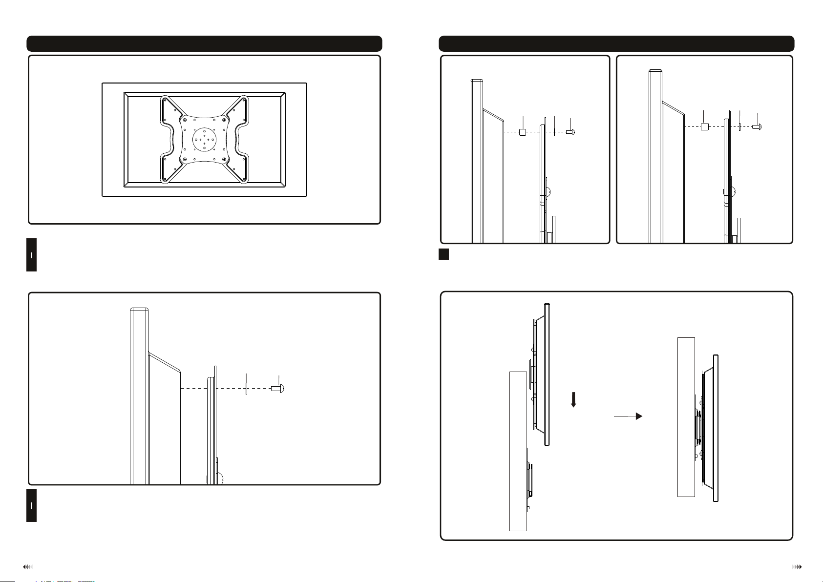
fig. 3.1
NOTE: For flat back screens proce ed to s tep 3 -1. F or bu mp- out or recessed back scre en sk ip to s tep 3 -2.
For Flat Back Screen
3
• Begin with the shortest length screw, hand thread through washer and adapter bracket into screen as shown below.
• Screw must make at least three full turns into mounting hole and fit snug into place. Do not over tighten.
1
• If screw cannot make three full turns into screen, select a longer length screw from the baffled fastener pack.
Repeat for remaining mounting holes, level brackets and tighten screws.
NOTE: Spacer may not be used, depending upon the type of screen.
M-I
M-B
M-J
M-M
Hang The Bracket Mounted Display Onto The Wal l Pl at e
4
After the wall plate has been safel y sec ure d to th e wal l, li ft yo ur di splay careful ly an d ins ert t he di splay
rails into the wall plate rail (NOT E: it is eas ier t o ins tal l by ti lti ng th e dis play sligh tly i n hor izo ntal directio n)
as sh own in fig .3.1.
Important: Ma ke su re th e dis pla y is co rre ctly hooked bef ore l oos eni ng the display.
M-K
M-D
M-F
fig. 3.3 fig. 3.4
M-N
M-L
M-H
M-I
M-J
M-K
M-L
For Bump-out or Recessed Back Screen
3
• Begin with longer length screw, hand thread throu gh washer, adapter bracket and spacer into scree n as
shown below.
2
• Screw must make at least three full turns into mounting hole and fit snug into place. Do not over tighten.
M-A
M-C
M-E
M-G
fig. 3.2
• If screw cannot make three full turns into screen, select a longer length screw from the baffled fastener pack.
Repeat for remaining mounting holes, level brackets and tight en screws.
wall
wall
fig. 4.1
65
 Loading...