

2005/01
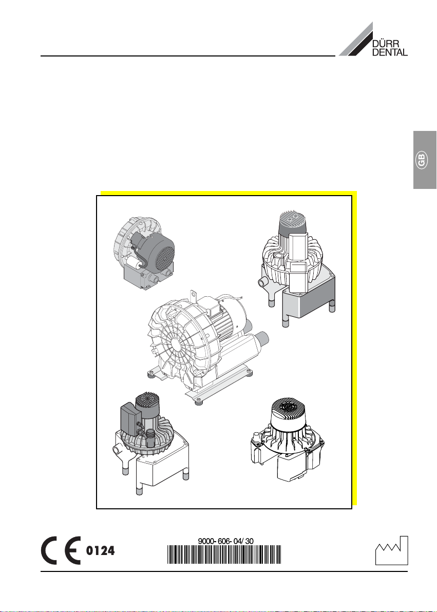
Installation and Operating Instructions
V 250 / V 300 S / V 600 / V 900 / V 1200
Suction Unit

2
Contents
Important Information
1. Notes......................................................... 4
1.1 Test of conformity .............................. 4
1.2 General Notes.................................... 4
1.3 General Safety Notes ........................4
1.4 Using Peripheral Devices ..................5
1.5 Safety notes concerning electric
current................................................5
1.6 Warnings and Symbols .....................5
2. Product information ................................ 6
2.1 Correct Usage ................................... 6
2.2 Incorrect usage ................................. 6
3. Delivery Contents .................................... 6
3.1 V 250 .................................................. 6
3.2 V 300 S ..............................................6
3.3 V 600 .................................................. 7
3.4 V 900 .................................................. 7
3.5 V 1200 ................................................ 7
4. Technical Data ......................................... 8
4.1 V 250 .................................................. 8
4.2 V 300 S ..............................................9
4.3 V 600 ................................................ 10
4.4 V 900 ................................................ 11
4.5 V 1200 .............................................. 12
5. Circuit Diagram ...................................... 13
6. Functional description ..........................13
Installation
7. Set-up ..................................................... 14
7.1 Installation room ..............................14
7.2 Set-up alternatives ........................... 14
7.3 Condensation trap ........................... 14
7.4 Plumbing materials .......................... 15
7.5 Hose material................................... 15
7.6 Pipe installation................................ 15
8. Electrical Connection ............................ 15
8.1 Connection details ...........................15
8.2 Control unit ......................................16
8.3 Connecting to terminal box ............. 16
9. Commissioning .....................................17
Care
10. Disinfecting and cleaning
suction units .......................................... 18
11. Maintenance........................................... 18
Disposal
12. Appliance disposal................................18
Trouble-shooting
13. Tips for Technicians .............................. 19
3

Important Information
1. Notes
1.1 Test of conformity
This product was tested for conformity to the
Guidelines 73/23/EWG + 89/336/EWG of the
European Union and has been found to satisfy
all criteria of these guidelines.
1.2 General Notes
• These Installation and Operating Instructions
form an integral part of the unit. They must
be kept close to the unit at all times. Precise
observance of these instructions is a precondition for use of the unit for the intended
purpose and for its correct operation. New
personnel must be made aware of the
contents, and they should be passed on to
future operating staff.
• Safety for the operator as well as troublefree operation of the unit are only ensured if
use is made of original equipment parts.
Moreover, use may only be made of those
accessories that are specified in the
technical documentation or that have been
expressly approved and released by Dürr
Dental for the intended purpose.
• Dürr Dental cannot guarantee for the safety
or proper functioning of this unit in the case
where parts or accessories are used which
are not supplied by Dürr Dental.
• Dürr Dental are only responsible for the
equipment with regard to safety, reliability
and proper functioning where assembly,
resettings, changes or modifications,
extensions and repairs have been carried
out by Dürr Dental or an agency authorized
by Dürr Dental and if the equipment is used
in conformity with the Installation and
Operating Instructions.
• These Installation and Operating Instructions
conform to the relevant version of the
equipment and the underlying safety
standards valid at the time of going to press.
All switches, processes, trade marks,
software programs and appliances named in
this document are registered names.
• Any reprinting of the technical
documentation, in whole or in part, is subject
to prior approval of Dürr Dental being given
in writing.
1.3 General Safety Notes
This appliance has been designed and
constructed by Dürr Dental so that correct
usage of the appliance is virtually free of any
possible injury or danger. In spite of this, we
feel it is our duty to mention the following
safety measures in order to prevent any
possible danger.
• When using this appliance all local and
relevant regulations must be observed!
Converting or modifying the appliance in
any way is strictly prohibited. In such cases,
any and all guarantees immediately become
invalid. The operation of modified
appliances can be punishable by law. In the
interests of trouble-free operation the
operator is responsible for observing these
regulations.
• Retain the packaging for possible return of
the product to the manufacturers. Ensure
that the packaging is kept out of the reach of
children. Only the original packaging
provides adequate protection during
transport of the unit.
Should return of the product to the
manufacturers be necessary during the
guarantee period, Dürr Dental accepts no
responsibility for damage occurring during
transport where the original packaging was
not used!
• Before every use the operator must check
the functional safety and the condition of the
appliance.
• The operator must be knowledgeable in the
operation of the appliance.
• The product is not designed to be used in
medical treatment areas where there exists
the danger of explosion. Areas where
explosions could occur are those where
flammable anesthetic material, skin
cleansers, oxygen and skin disinfectants are
present. This appliance is not to be used in
areas where the atmosphere could cause
fire.
4
1.4 Using Peripheral Devices
• Units may only be connected to the system
or to other units when it has been
established that there is no reduction of
safety for the patient, the operator or the
environment through such connection.
Where it is not absolutely clear from the
documentation whether safety is reduced by
such connection, then the operator must
establish, e.g. by contacting either the
manufacturer or an expert, that there is no
reduction of safety for the patient, the
operator or the environment through such
connection.
1.5 Safety notes concerning electric
current
• This unit may only be connected to a
standard approved earthed electrical socket
(V 600, V 900, V 1200).
• Before connecting the appliance to the
mains, check that the frequency and
voltages given for the appliance match
those of the available power supply.
• Before commissioning the appliance all
connections must be checked for possible
damage. Damaged connections, plugs and
sockets should be replaced immediately.
• Never touch patients and open sockets of
the appliance simultaneously.
• All relevant electrical rules and regulations
must be observed during installation and
when carrying out any repairs or
maintenance on the appliance.
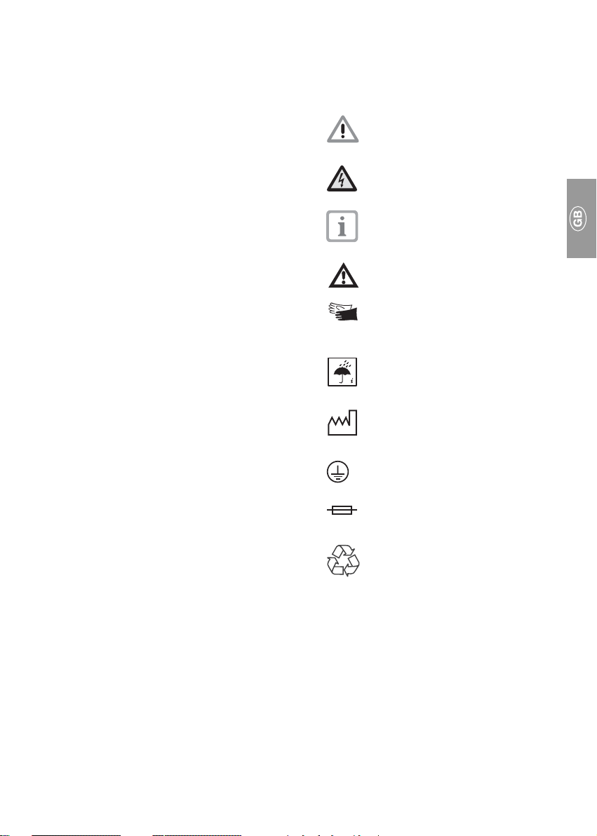
1.6 Warnings and Symbols
The operating and installation instructions
contain the following labeling and symbols for
especially important information.
Restrictions and regulations
concerning the prevention of injury
or damage.
Warning concerning dangerous
electrical voltage.
Special instructions concerning
economic use of the appliance or
other notes.
Obseve notes in supplementary
documentation
For added safety of operators
protective gloves should be worn
while working on the Suction Units.
Take environmental influences into
consideration.
Date of manufacture.
Ground connection.
Fuse.
Recycling
~ Single phase AC current.
3~ Three-phase AC current.
3N~ Three-phase AC current with central
conductor.
5

2. Product information
3. Delivery Contents
2.1 Correct Usage
The suction units are used in connection with
seperation units, in dry suction systems, in
dental surgeries or dental clinics.
The suction unit must be cleaned and
disinfected according to manufacturer’s
instructions.
For correct usage the Installation and
Operating Instructions, as well as conditions
concerning installation, operation and
maintenance must be observed.
It is absolutely necessary that
secretion and air be separated prior to
the suction unit.
2.2 Incorrect usage
Do not suck off any combustible or explosive
mixtures. The appliances are unsuitable for
use as vacuum cleaners. No secretion or any
other fluid must be sucked into the suction
unit.
Any other use or use beyond what is specified
is deemed to be not for the intended purpose.
The manufacturer accepts no liability for
damage resulting therefrom. All risk is borne
soleley by the user.
Those items listed under Special
Accessories are not part of the
supplied delivery contents but can be
ordered separately.
3.1 V 250
3.1.1 Delivery contents
Type 0741-01
Model with 230V, 50Hz
3.1.2 Special accessories
Sterile filter .................................... 7120-143-00
Set of connecting pieces ............. 0741-001-00
Condensation collector ................ 7120-700-00
Wall mounting bracket ................. 7120-991-00
3.2 V 300 S
3.2.1 Contents
Model 7119-01/002
Typ 230 V, 1~, 50 - 60 Hz
with control unit
3.2.2 Accessories
Connector set ............................... 7119-001-00
Suction hose LW 30, grey ............ 9000-317-27
Hose LW 19 .................................. 9000-317-22
Hose LW 30, Aluminium ............... 9000-317-37
Condensation collector ................ 7119-700-00
3.2.3 Special Accessories
Wall mounting ............................... 7130-190-00
Housing ........................................ 7122-200-00
Exhaust bacterial filter with
accessories .................................. 7120-143-00
6

3.3 V 600
3.3.1 Delivery contents
Type 7127-01/002
Model with 230V, 1~, 50Hz
Type 7127-02/002
Model with 400V/230V, 3~, 50-60Hz
with control board 400V, 3~
Type 7127-02/003
Model with 400V/230V, 3~, 50-60Hz
with control board 230V, 3~
3.3.2 Accessories
Connecting pieces + tubes ......... 7127-001-00
Condensation collector ................ 7130-700-00
Control board
230V, 1~, 50Hz ............................ 0700-500-50
230V, 3~, 50-60Hz ....................... 0732-100-53
400V, 3~, 50-60Hz ....................... 0732-100-52
3.3.3 Special accessories
Wall mounting bracket ................. 7130-190-00
Sound absorber ........................... 9000-416-06
Sterile filter .................................... 0732-001-00
Sterile filter mounting ................... 0732-000-06
3.4 V 900
3.4.1 Delivery contents
Type 7130-01/002
Model with 230V, 1~, 50Hz
3.5 V 1200
3.5.1 Delivery contents
Type 0730-01
Model with 400V, 3~, 50Hz
3.5.2 Accessories
Base plate .................................... 7130-190-04
Connecting pieces + tubes ......... 0730-001-00
Control board ............................... 0732-100-54
Condensation collector ................ 7130-701-00
3.5.3 Special accessories
Sound absorber ........................... 9000-416-06
Fine filter ....................................... 0732-001-00
Mounting for sterile filter .............. 0732-000-06
Type 7130-02/002
Model with 400V/230V, 3~, 50Hz
with control board 400V, 3~
Type 7130-03/002
Model with 230V, 3~, 50Hz
with control board 230V, 3~
3.4.2 Accessories
Connecting pieces + tubes ......... 7130-001-00
Control board
230V~, 1~, 50Hz .......................... 0732-100-50
400V~, 3~, 50Hz .......................... 0732-100-52
230V~, 3~, 50Hz .......................... 0732-100-53
Condensation collector ................ 7130-700-00
3.4.3 Special accessories
Wall mounting bracket ................. 7130-190-00
Sound absorbing hood ................ 7133-991-00
Sound absorber ........................... 9000-416-06
Sterile filter .................................... 0732-001-00
Mounting for sterile filter .............. 0732-000-06
7

4. Technical Data
4.1 V 250
Type 0741 -01
Voltage V 230 / 1~
Frequency Hz 50
Rated current A 1.85
Starting current A 9.5
Electric power W 415
Rotary frequency min
Weight kg 10
Sound level* dB(A), ±1,5 approx. 64
Operating time %ED 100
Temperature range
Appliance in operation °C +10 to +40
Storage and transportation °C -10 to +60
Humidity of air
Appliance in operation max. 70%
Storage and transportation max. 95%
Protection system IP 44
Protection class I
Vacuum connection ø 30 mm (outside)
Exhaust connection ø 30 mm (outside)
-1
2810
* According to EN ISO 1680 air noise emissions;
measured in soundproof room. Higher values will be
achieved in reverberant rooms.
8

4.2 V 300 S
Type 7119 -01
Voltage V 230 / 1~
Frequency Hz 50-60
Rated current A 2.9 - 3.7
Starting current A 8,2 - 9.1
Motor protection switch A Motor winding overheat protector 160°C (±5°C)
Electric power W 580 - 800
Rotary frequency min
Weight
without housing kg 12,5
Sound level* dB(A), ±1,5 approx. 63
Operating time %ED 100
Temperature range
Appliance in operation °C +10 to +40
Storage and transportation °C -10 to +60
Humidity of air
Appliance in operation max. 70%
Storage and transportation max. 95%
Protection system IP 24
Protection class I
Vacuum connection DürrConnect Spezial (hose ø 30 mm (inner))
Exhaust connection DürrConnect Spezial (Aluminium hose ø 30 mm (inner))
-1
2750 - 3100
Protective low voltage V 24 ~
Power output VA 4
* According to EN ISO 1680 air noise emissions; measured in soundproof room. Higher values will
be achieved in reverberant rooms.
9

4.3 V 600
Type 7127 -01 -02
Voltage V 230 / 1~ 400 / 3~ 230 / 3~
Frequency Hz 50 50 - 60 50 - 60
Rated current A 5 1.8/2.3 3.2/4.0
Starting current A22 89
Electric power W 1100 980 1420
Rotary frequency min
Weight kg 25
Sound level* dB(A), ±1,5 approx. 63
Operating time %ED 100
Temperature range
Appliance in operation °C +10 to +40
Storage and transportation °C -10 to +60
Humidity of air
Appliance in operation max. 70%
Storage and transportation max. 95%
Protection system IP 44
Protection class I
Vacuum connection ø 40 mm (DN 40)(outside)
Exhaust connection ø 50 mm (outside)
Air-bleed setting mbar approx. 170 (170 hPa)
* According to EN ISO 1680 air noise emissions; measured in soundproof room. Higher values will
be achieved in reverberant rooms.
-1
2850 2850 3350
10

4.4 V 900
Type 7130 -01 -02 -03
Voltage V 230 / 1~ 230 / 400 / 3~ 230 / 3~
Frequency Hz 50 50 50
Rated current A 5.5 4 / 2.5 4
Starting current A 29 26 / 16 24
Electric power W 1480 1520 1420
Rotary frequency min
Weight kg approx. 35
Sound level* dB(A), ±1,5 approx. 64
Operating time %ED 100
Temperature range
Appliance in operation °C +10 to +40
Storage and transportation °C -10 to +60
Humidity of air
Appliance in operation max. 70%
Storage and transportation max. 95%
Protection system IP 44
Protection class I
Vacuum connection ø 50 mm (DN 50)(outside)
Exhaust connection ø 50 mm (outside)
Air-bleed setting mbar aprox. 170 (170 hPa)
* According to EN ISO 1680 air noise emissions; measured in soundproof room. Higher values will
be achieved in reverberant rooms.
-1
2770 2820 2820
11

4.5 V 1200
Type 0730 -01
Voltage V 230/400 / 3~
Frequency Hz 50
Rated current A 5.5 / 3.2
Starting current A28
Electric power W 1500
Rotary frequency min
Weight kg 33
Sound level* dB(A), ±1,5 65
Operating time %ED 100
Temperature range
Appliance in operation °C +10 to +40
Storage and transportation °C -10 to +60
Humidity of air
Appliance in operation max. 70%
Storage and Transportation max. 95%
Protection system IP 54
Protection class I
Vacuum connection ø 50 mm (outside)
Exhaust connection ø 50 mm (outside)
Air-bleed setting mbar approx. 160
-1
2930
(160 hPa)
* According to EN ISO 1680 air noise emissions;
measured in soundproof room. Higher values will be
achieved in reverberant rooms.
12

5. Circuit Diagram
12
4
5
3
6. Functional description
The V-Suction units (4) are used with dry suction systems. The advantage is that the suction units
can be installed in any suitable room without paying attention to the arrangement of the wiring (also
in upper floor or basement). The necessary air flow and vacuum requirements are achieved using
the by-pass duct compression principle.
A condensation trap (3) is fitted to the vacuum side of the V-Suction unit (V 250 special accessory),
which collects any condensation that accumulates in the pipe system and removes this externally.
An air-bleed (5) in the condensation trap (only types V 600, V 900, V 1200) protects the V-Suction
unit from over-heating and provides for constant suction performance.
If one of the units has a loss in suction then ca. 300 l air/min. is sucked in via the suction channels.
The speed at entry into the channel is ca. 50 m/s. In the suction pipes the speed of flow is reduced
to 15-20 m/s. This speed is enough to guarantee reliable transport of all dirt particles.
In the hose manifold (2) is a fine filter which retains all larger particles. In the separator unit (1) there
is a reliable removal of all remaining dirt components. By this means only air with no fluid or
particles is transported from the separator to the suction motor. The secretions in the separator unit
flow automatically through the drainage hose into the drainage system of the treatment unit.
13

Installation
7. Set-up
7.1 Installation room
• The room temperature must not fall below +
10 ° C in winter and in the summer must not
rise above + 40 ° C.
• Installation in special-purpose rooms, e.g. in
heating rooms, must be checked concerning
building regulations beforehand.
• Installation in wet or damp rooms is
1
2
prohibited.
• When installing in a cupboard or similar,
check that there is sufficient ventilation, i.e.
check that air vents are present in the
cupboard. If air flow is insufficient then a fan
should be installed
7.2 Set-up alternatives
A great advantage of dry suction systems is
that the suction unit may be installed in any
suitable room (also in upper floor or
basement) without worrying about the
available plumbing.
• Installation of the suction unit directly onto
the floor (depending on type).
• Installation of the suction unit onto a special
frame and then onto the floor.
• From the wall on a special wall mounting
bracket.
For reasons of hygiene and in order to
avoid both smell and problems of heat
we recommend the exhaust air to be
fed outside the building and to fit a
sterile filter
14
7.3 Condensation trap
Where a condensation trap is present, this
should be fitted first before installation of the
suction unit. Where the suction unit is to be
fitted on the top floor of the building then the
condensation trap, should be fitted at the
lowest point of any plumbing.
Installation instructions for the condensation
trap are delivered together with that unit.
3

7.4 Plumbing materials
Only the following materials may be used
for the pipe system:
Vacuum-sealed HT-drain pipe made from
polypropylene (PP, polypropen), chlorinated
polyvinyl-chloride (PVC-C), unplasticized
polyvinyl-chloride (PVC-U) or polyethylene
(PEh).
The following materials may NOT be
used:
Acrylnitril-Butadien-Styrol (ABS)
and Styrol-Copolymer-Blends
(SAN+PVC)
7.5 Hose material
Only flexible spiral hoses of PVC with spiral
fittings or hoses of this quality should be used
for the drainage and suction systems.
The following materials may NOT be
used:
Hoses which are not capable of
withstanding the dental
disinfectants and chemicals used,
or hoses which are of rubber or full
PVC tubes which are not sufficiently
flexible.
7.6 Pipe installation
• Drainage pipes, e.g. after the condensation
trap, must be installed according to the local
rules and regulations.
The connection between the plumbing
system and the inlet to the suction unit
should be kept as small as possible
and as straigt as possible with no
bends using the flexible hose
supplied. This will avoid unnecessary
vibration on the plumbing system.
8. Electrical Connection
Before commissioning check that the electrical
supply conforms with that on the appliance
label.
Electrical connection to the power supply must
be carried out by inserting into the circuit a
universal circuit breaker (universal switch or
universal line safety switch (fuse)) with >3mm
contact gap.
The suction unit may be connected via the
control system to an external junction box.
Fuse rating: 16 AT
8.1 Connection details
100/110V / 230V / 400V connection (power
supply, fixed):
• NYM-J 3x1.5mm² / 5x1.5mm²
100/110V / 230V / 400V connection (power
supply, flexible):
The connection between the suction unit and
the external control unit or between appliance
socket and suction unit should either be
composed of a PVC-connector:
H05 VV-F 5G1.5mm² / 5G1.5mm²
or of rubber:
H05 RN-F 3G1.5mm² / 5G1.5mm²,
H05 RR-F 3G1.5mm² / 5G1.5mm².
A cable of cross-section 1 mm² may be usde
when installing the V 250, V 300 S.
24V control line, protective low voltage for
• Hose manifold
• Selector switch
• Spittoon valve
Fixed installation: (N)YM (St)-J 4x1.5mm²
protected casing.
Flexible installation: PVC-Data connection
LiYCY 4x1.0mm² with protected casing as
used for telephone or information systems or
light PVC-cable with protected casing.
24 V Control line for V 300 S
Flexible cable connection: PVC-Data cable
LiYY 3 x 0.5 mm²
Order-No. 9000-118-83
15

8.2 Control unit
The suction unit can be operated via a control
unit, supplied with the unit or available as
special accessory. Connection plans and
circuit diagrams can be found in the Installation and Operating Instructions for the Control
Unit.
8.3 Connecting to terminal box
Connect power supply from the control unit to
the appropriate terminals on the motor terminal
box (see also connection plans in the Installation and Operating Instructions for the Control
Unit).
4
8.3.1 V 250, 230V (Fig. 4)
Blue = blau
Red = rot
White = weiss
Brown = braun
SL = PE
8.3.2 V 300 S, 230V, (Fig. 5)
with Control Unit integrated into sound-
reducing housing.
X1 Power supply connection
X2 Motor connection
X3 Connection to manifold
24VAC / max. 80mA
X4 Control signal output
24VAC / max. 20mA
5
8.3.3 V 600, 230V 1~
V 900, 230V 1~
16
6

8.3.4 V 600, 230V/400V 3~
V 900, 230V/400V 3~
7
Handling the terminal strip for V 600 and V 900
8
8.3.5 V 1200, 230V/400V 3~
9. Commissioning
• Turn on at the appliance or central surgery
on switch.
• Carry out function check and check all
connections for leakage etc.
• Carry out electrical check according to
national regulations and record results as
9
appropriate, e.g. on the technical report.
17

Care
10. Disinfecting and cleaning suction units
After every treatment
should be sucked through the system; through
both the small and the large suction hoses,
even if only the saliva suction hose was used
during treatment.
The cleaning effect is increased
considerably by using the larger
suction hose.
a glass of cold water
11. Maintenance
The V-Suction unit itself requires no
maintenance.
The exhaust from the suction unit contains
bacteria. As the separation techniques within
the suction unit are only designed to remove
fluids and particles, germs which are present
are sucked through the system. For this
reason we recommend that a sterile filter be
fitted into the exhaust sytem and that this filter
be changed at least once a year.
Before midday break and at the end of the
day
a non-aggressive and non-foaming
cleaning and disinfecting agent (e.g. Orotol
Plus) should be used to clean and disinfect
the suction system.
Do not use a foaming cleaning
agent, as this can damage the
suction unit.
The suction unit may not be used to
extract solvents such as Acetone or
anything similar. These agents
attack the plastic and rubber parts
of the unit.
Further information can be found in the
instruction booklets "Disinfection and Cleaning
of Suction Units“, order number 9000-605-10
and in "Cleaning Instructions for contaminated
Suction Units", order number P007-235-01.
Disposal
12. Appliance disposal
The machine may be contaminated.
Please inform the waste disposal
contractors in order that they can take
the appropriate safety measures.
Non-contaminated plastic parts of the
suction unit can be disposed of for
recycling.
The control units, electronic PCB and other
components should be disposed of as electric
waste. The remaining metal parts (e. g. turbine
housing) should be disposed of as metallic
waste.
If returning the appliance, e.g. to your local
Depot or to Dürr Dental, make sure that all
connections are closed.
18

Trouble-shooting
13. Tips for Technicians
The following steps concerning troubleshooting and correction of faults are only
designed for our technicians. Repairs are
only to be carried out by qualified
technicians.
Problem
1. Suction unit
does not start.
2. Suction unit power
too low.
Possible cause
• No mains supply voltage.
• Under or over voltage.
• Motor protection switch set too
low (see section 4. Technical
Data for values).
• Motor protection switch defect.
• Turbine is blocked due to solid
particles or sticky dirt: Motor
protection switch activated.
• Mechanical movements of
turbine hindered by dirt.
• Leaks in the suction unit
plumbing.
Solution
• Check mains supply, fuses in the
control unit and/or on the PCB,
and replace if necessary.
Check supply voltage.
• Check the supply voltage, if
necessary inform electrician.
• Check current. Set motor
protection switch to the correct
value.
• Check motor protection switch;
replace, if necessary.
• Dismantle the suction unit and
clean the turbine thoroughly.
• Dismantle the suction unit and
clean the turbine thoroughly.
• Check all pipes, hoses and
connections for leaks and
replace if necessary.
19

20
 Loading...