

Page 1
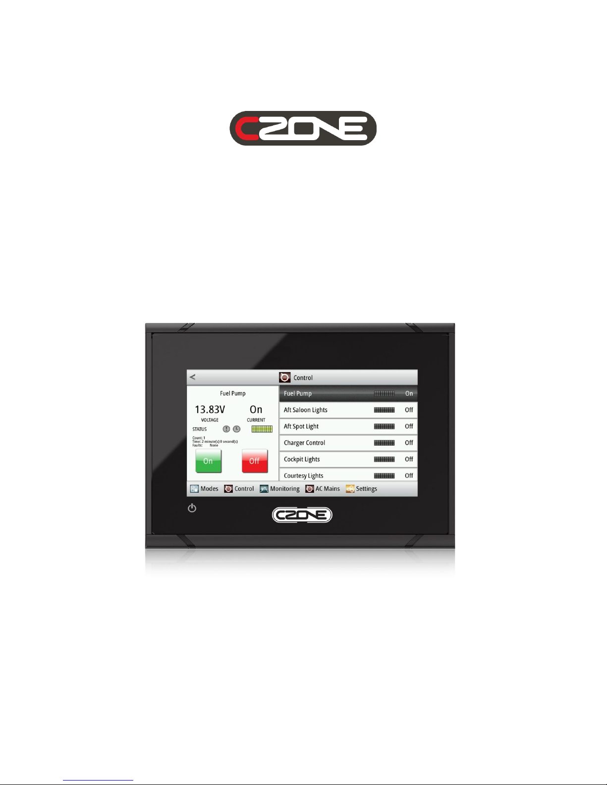
Touch 5 User & Installation Manual
v1.1
Page 2

EN / CZone Touch 5 User & Installation Manual
2
Copyright
This document is copyright 2016 under the Creative Commons agreement. Rights are granted to
research and reproduce elements of this document for non-commercial purposes on the condition that
BEP Marine is credited as the source. Electronic re-distribution of the document in any format is
restricted, to maintain quality and version control.
Important
BEP Marine strives to ensure all information is correct at the time of printing. However, the company
reserves the right to change without notice any features and specifications of either its products or
associated documentation.
Translations: In the event that there is a difference between a translation of this manual and the
English version, the English version should be considered the official version.
It is the owner’s sole responsibility to install and operate the device in a manner that will not cause
accidents, personal injury or property damage.
Page 3

3
EN / CZone Touch 5 User & Installation Manual
Table of Contents
1 GENERAL INFORMATION ............................................................................................................. 5
1.1 Description .............................................................................................................................. 5
1.2 Overview ................................................................................................................................. 5
1.2.1 Front Controls .................................................................................................................. 5
1.2.2 Rear Connections............................................................................................................ 5
1.2.3 In The Box ....................................................................................................................... 6
1.2.4 Card Reader .................................................................................................................... 6
2 INSTALLATION ............................................................................................................................... 7
2.1 Mounting Location ................................................................................................................... 7
2.2 Panel Mounting ....................................................................................................................... 7
2.3 Wiring ...................................................................................................................................... 7
2.4 Power Control Connection ...................................................................................................... 8
2.4.1 Power Control Unconnected ........................................................................................... 8
2.4.2 Power Control To Supply Positive (Auto On) .................................................................. 8
2.5 NMEA 2000 Backbone ............................................................................................................ 8
3 GETTING STARTED ....................................................................................................................... 9
3.1 First Power Up ......................................................................................................................... 9
4 OPERATIONS IN DETAIL ............................................................................................................. 11
4.1 Accessing a Function within its Group .................................................................................. 11
4.1.1 Groups of Functions, and the Tabbed Main Menu ........................................................ 11
4.2 CZone Functions by Group ................................................................................................... 12
4.2.1 Modes ............................................................................................................................ 12
4.2.2 Control ........................................................................................................................... 14
4.2.2.1 DC Control and AC Control Circuits .......................................................................... 15
4.2.3 Monitoring ...................................................................................................................... 16
4.2.3.1 DC Monitoring ........................................................................................................... 16
4.2.3.2 AC Monitoring ............................................................................................................ 18
4.2.3.3 Tanks ......................................................................................................................... 19
4.2.3.4 Alarms ....................................................................................................................... 20
4.2.3.5 Systems in Operation ................................................................................................ 22
4.2.4 Settings ......................................................................................................................... 23
4.3 Updating Software ................................................................................................................. 23
4.3.1 Checking Current Software Version .............................................................................. 23
4.3.2 Updating Software via microSD .................................................................................... 23
4.4 Wireless Interface Setup ....................................................................................................... 24
4.5 Connecting iPad to Touch 5 .................................................................................................. 25
5 SPECIFICATIONS ......................................................................................................................... 27
Page 4

EN / CZone Touch 5 User & Installation Manual
4
5.1 Technical Specifications ........................................................................................................ 27
5.2 Dimensions ............................................................................................................................ 27
6 EC DECLARATION OF CONFORMITY ........................................................................................ 28
Table of Figures
Figure 1. Battery & Power Connections ................................................................................................... 7
Figure 2. Touch 5's Tab based Main Menu ........................................................................................... 11
Figure 3. Home-page for the Monitoring Functional Group ................................................................... 11
Figure 4. Modes Configuration Example ................................................................................................ 13
Figure 5. Control Page ........................................................................................................................... 14
Figure 6. Monitoring Page ...................................................................................................................... 16
Figure 7. CZone Alarm Severity Definition ............................................................................................. 20
Figure 8. CZone iPad App Favourites Page Example ........................................................................... 26
Figure 9. Dimensions ............................................................................................................................. 27
Page 5
5
EN / CZone Touch 5 User & Installation Manual
1 General Information
1.1 Description
The CZone Touch 5 is a 5” colour touch-screen, which operates as a Display Interface on any new or
existing CZone network. It is designed for a wide range of applications, and can withstand the harsh
marine and recreational vehicle environments. With its bright touch screen and multiple levels of
backlighting, the Touch 5 provides fast and positive operation in all visibility conditions. Together with
toughened glass and water proofing, this makes it suitable for exposed locations. The Touch 5 can
also be configured as a Wireless Interface, allowing wireless control and monitoring with the CZone
iPad App.
1.2 Overview
1.2.1 Front Controls
1.2.2 Rear Connections
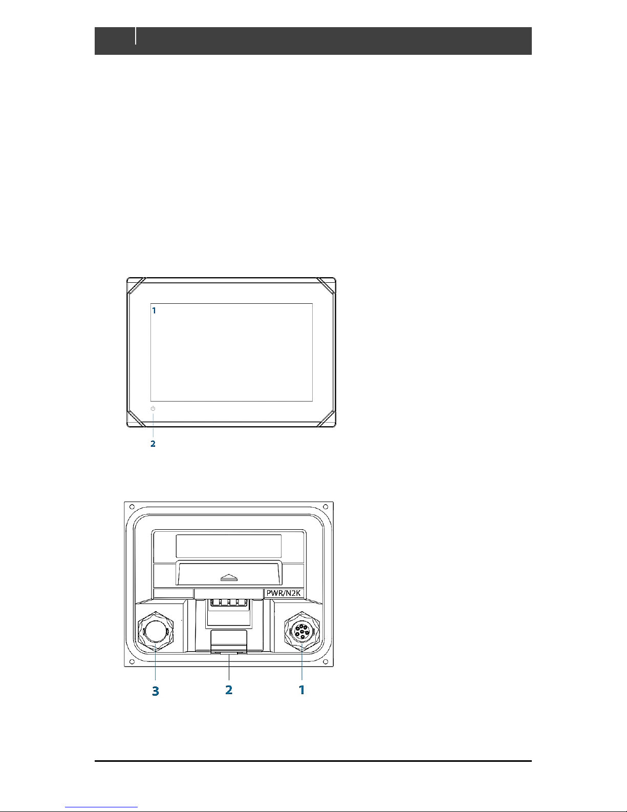
1. 12VDC Power and NMEA 2000
2. MicroSD Card Reader
3. Unused
1. Touch Screen
2. Power Button – Press and
hold to turn the unit ON
Page 6
EN / CZone Touch 5 User & Installation Manual
6
1.2.3 In The Box
1.2.4 Card Reader
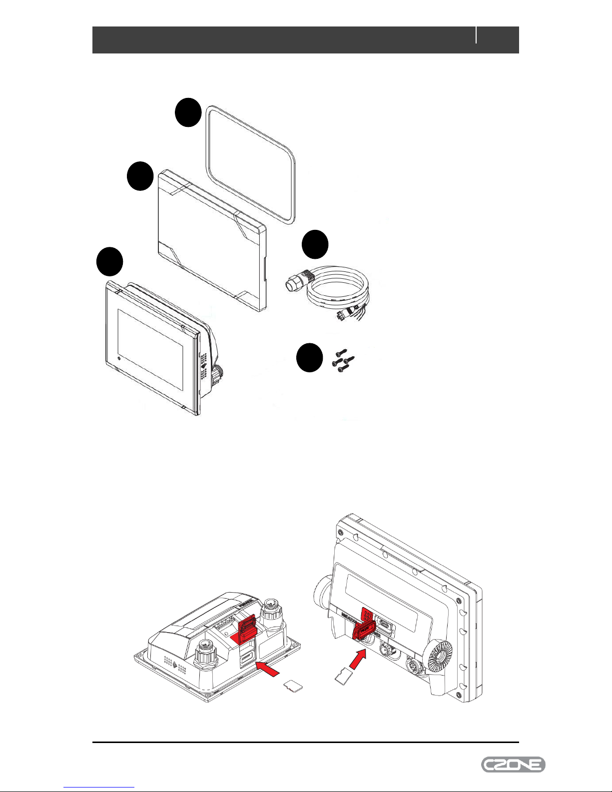
Used for attaching a microSD memory card. The memory card can be used for software updates. The
card reader door is opened by pulling the rubber cover open. The card reader door should always be
securely shut immediately after inserting or removing a card, in order to prevent possible water
ingress.
1 2 3
5
4
1. Touch 5
2. Sun Cover
3. Panel mount gasket
4. Power/NMEA cable
5. Panel mount screws
Page 7
7
EN / CZone Touch 5 User & Installation Manual
2 Installation
2.1 Mounting Location
Choose the mounting locations carefully before you drill or cut. The unit should be mounted so that
the operator can easily use the controls and clearly see the screen. Be sure to leave a direct path for
all of the cables. The unit has a high-contrast screen, and is viewable in direct sunlight, but for best
results install the unit out of direct sunlight. The chosen location should have minimal glare from
windows or bright objects. Choose an area where the unit will not be subjected to excessive vibration,
or heat. Good ventilation is required.
Warning!: Inadequate ventilation may cause the unit to overheat. The unit is designed to
operate in temperatures from -15° C to +55° C (+5° F to +131° F).
2.2 Panel Mounting
The screws and gasket used for panel mounting are included in the box. For mounting instructions,
refer to the Panel mounting template.
2.3 Wiring
Warning!: Before starting the installation, be sure to turn electrical power off. If power is left on
or turned on during the installation, fire, electrical shock, or other serious injury may occur. Be
sure that the voltage of the power supply is compatible with the unit.
Warning!: The unit has a voltage rating of 12 V DC, it is not suited for use with 24 V DC
systems.
The unit is powered by 12 V DC. It is protected against reverse polarity, under voltage, and over
voltage (for a limited duration). The plug of the supplied power cable has two discrete cables exiting
from it. The thickest of the two cables provides the following:
Power into the system (Red and Black wires).
Controlling power state of the unit (Yellow wire)
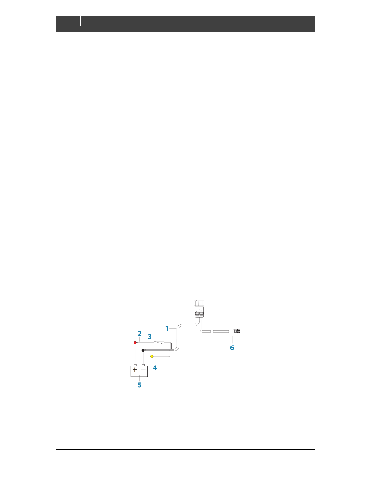
Figure 1. Battery & Power Connections
1. Power cable
2. 12 V DC positive wire (red) shown with fuse holder fitted
3. 12 V DC negative wire (black)
4. Power control wire (yellow)
Page 8

EN / CZone Touch 5 User & Installation Manual
8
5. 12 V DC supply
6. NMEA 2000 cable and connector
Connect Red to (+) DC using a 3 amp fuse. Connect Black to (-) DC.
2.4 Power Control Connection
The yellow Power Control wire in the power cable is an input that will turn on the unit when power is
applied.
2.4.1 Power Control Unconnected
Device will turn on when the power button on the front of the unit is pressed. Leave the yellow Power
Control wire disconnected and tape or heat-shrink the end to prevent shorting.
2.4.2 Power Control To Supply Positive (Auto On)
Device will turn on immediately when power is applied. Common the yellow wire with the red wire
after the fuse.
2.5 NMEA 2000 Backbone
Run an NMEA2000 cable from the NMEA2000 connector to an NMEA2000 network backbone
Page 9
9
EN / CZone Touch 5 User & Installation Manual
3 Getting Started
3.1 First Power Up
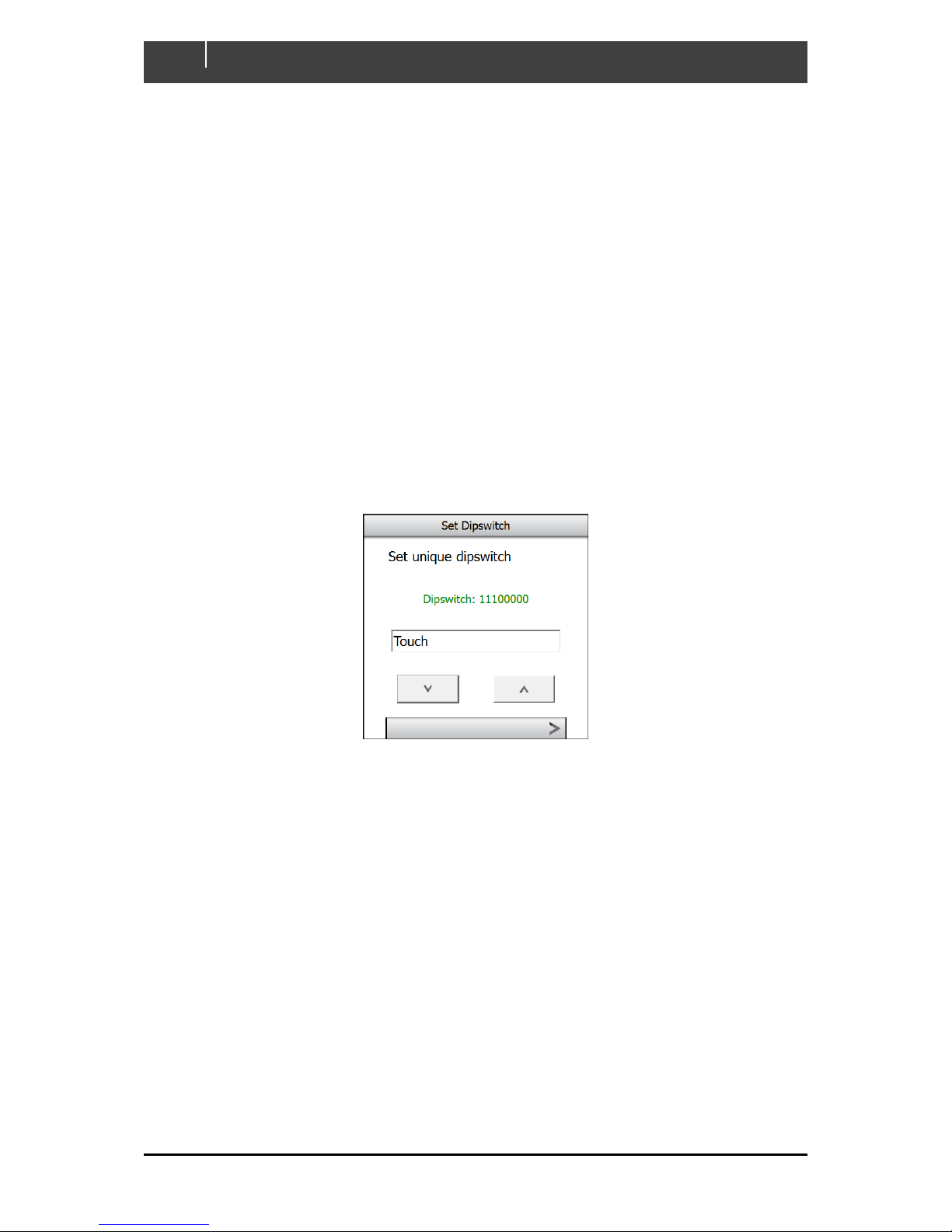
If connecting Touch 5 to an existing CZone network, ensure the display has been added to the CZone
configuration file and assigned a dipswitch. Every CZone device on a network requires a unique
dipswitch to operate correctly, and the Touch 5 has a virtual dipswitch. Refer to the CZone
Configuration Tool manual for this process.
1. Turn on the circuit breaker or switch supplying power to the Touch 5.
2. The CZone splash-screen will appear for about 10 seconds then the text ‘Starting
Configuration Claim’. Touch 5 will now read the CZone configuration file from the network.
3. When configuration has been successfully read the text ‘Configuration Successful’ will
appear. It is also possible to write the configuration to the network at a later date for new
installations.
4. Select the virtual dipswitch from the list of configured CZone devices, for new installations the
dipswitch can be set by selecting Dipswitch from the Settings > System page.
Page 10
EN / CZone Touch 5 User & Installation Manual
10
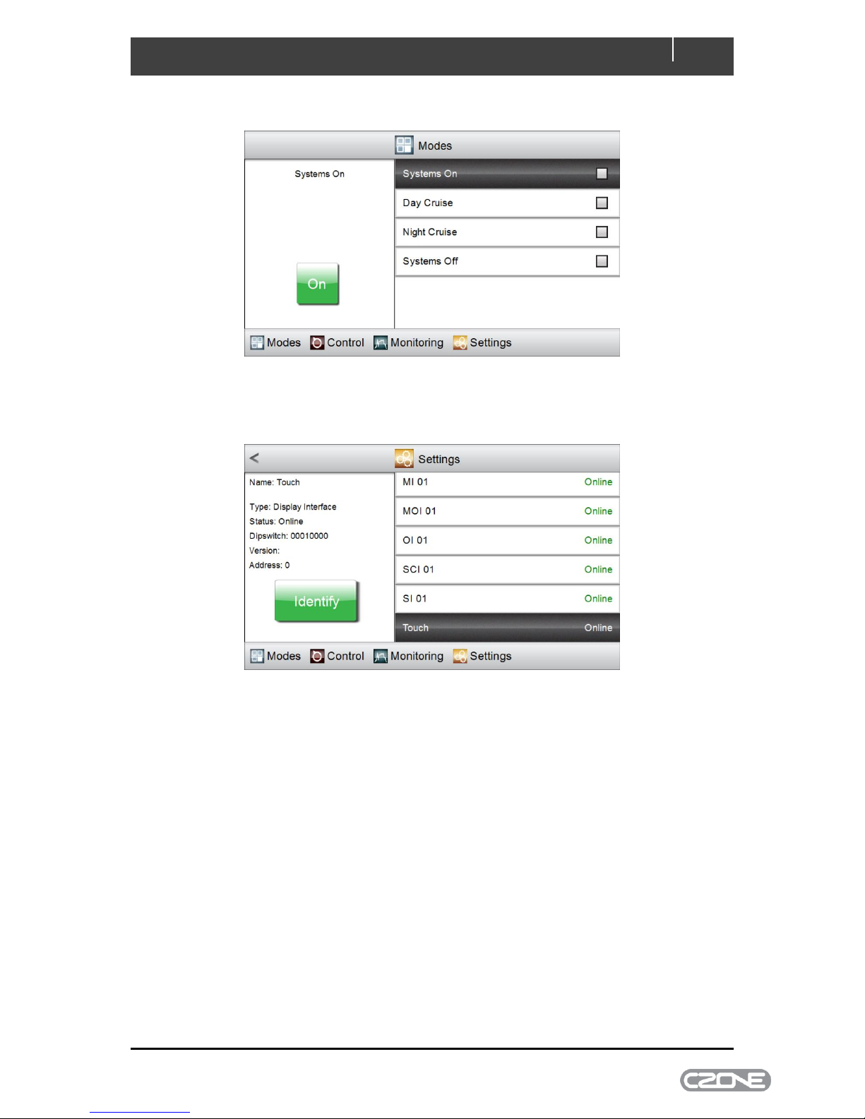
5. Once dipswitch has been set the Modes page from the configured system will appear.
6. To ensure network connections are good and that the display can see the rest of the CZone
devices go to the Settings > Network page and check configured modules are showing
‘Online’.
7. Update software if a newer version is available. Refer to Chapter 4.3 for this process.
8. Touch 5 is now ready for use.
Page 11
11
EN / CZone Touch 5 User & Installation Manual
4 Operations in Detail
4.1 Accessing a Function within its Group
4.1.1 Groups of Functions, and the Tabbed Main Menu
CZone operations are divided into four functional groups:
1. Modes - complete setups for operating the vessel in a consistent way: for example, when
docked; cruising at night or in daylight; at anchor; and so on
2. Control - individual control of the vessel’s equipment, such as pumps, lights, and power
isolators
3. Monitoring - measurement of the vessel’s devices and subsystems, including tank levels, AC
and DC power sources such as batteries and inverters, alarms and others
4. Settings - set CZone parameters, rather than other on-board equipment. This includes units
of measurement, backlight settings, time zones, etc.
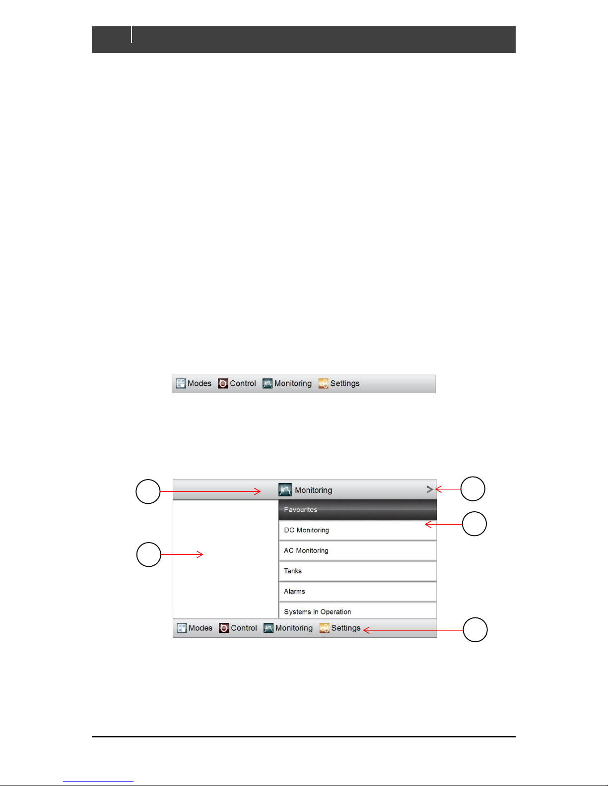
Touch 5 offers a tab-based main menu, with a “home tab” for each of the above functional groups.
(The menu is shown in Figure 2. Touch 5's Tab based Main Menu
It is displayed along the bottom of the screen at all times except when a keypad is shown.)
Figure 2. Touch 5's Tab based Main Menu
To access any function in a group, start by clicking its home tab. The GUI will display the tab’s home
page, a top-level selection with functions divided more finely into sub-categories. (See Figure 3 for an
example.)
Figure 3. Home-page for the Monitoring Functional Group
A Title, showing name of current functional group.
B Accept button. Clicking this has the same effect as clicking the highlighted sub-
category.
A B C
D
E
Page 12
EN / CZone Touch 5 User & Installation Manual
12
C Display panel. (This remains blank unless used by the current function)
D Sub-categories available for further selection. (In this example, clicking the Accept
button will drill down further into the highlighted Favourites sub-category.)
E Tab-based main menu.
4.2 CZone Functions by Group
4.2.1 Modes
The Modes group is very simple to navigate because it has only one level. This is deliberate:
changing modes is intended to reconfigure the systems operation as easily as possible. Modes will
vary between vessel or vehicle and are usually configured by the builder, although can be modified at
a later date with the CZone Configuration Tool.
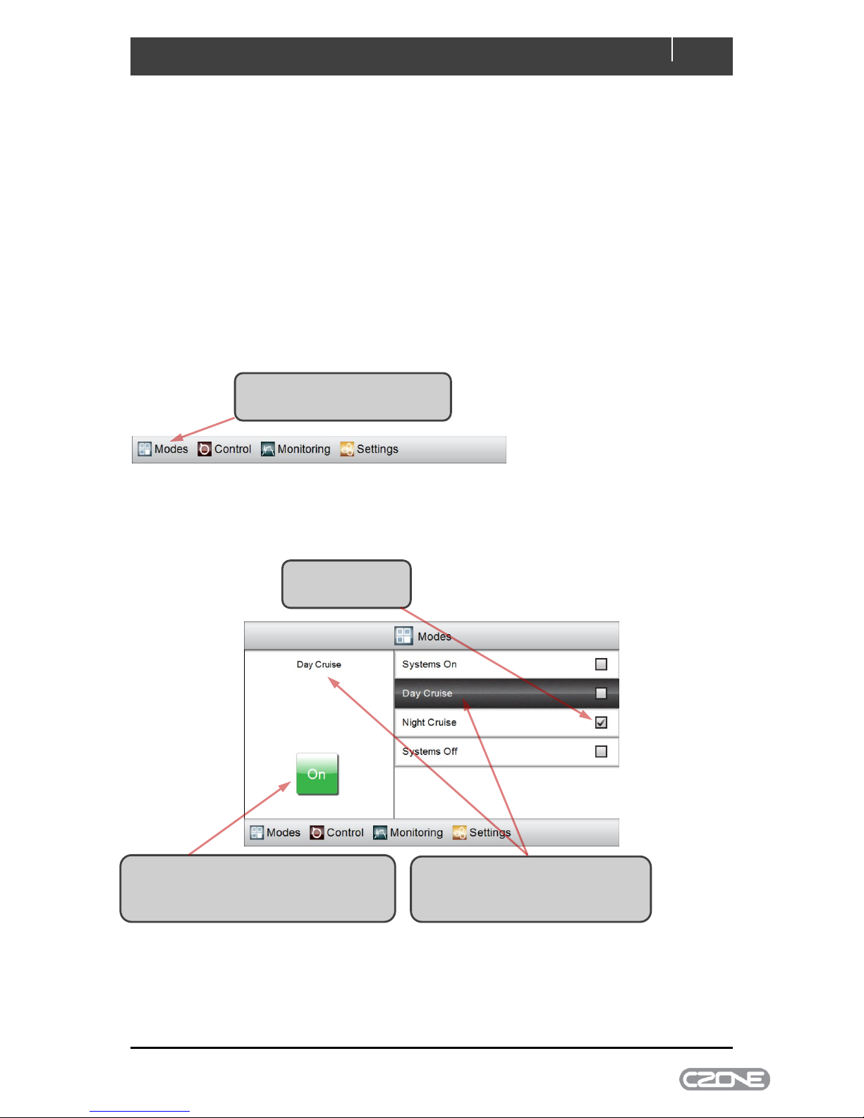
The Modes home-page appears, listing all available operating modes that have been configured for
the system. The topmost mode is highlighted. The following is an example screen showing how to
change modes:
1 Click Modes on the main menu
along the bottom of the screen.
The current mode
has a tick beside it
2 Click to highlight the mode that you
want to change to. Its name is
tracked in the display pane
3 Click On to confirm the mode change.
The tick moves to the new mode and
CZone changes the systems operation
Page 13
13
EN / CZone Touch 5 User & Installation Manual
Modes are configured by the builder using the CZone Configuration Tool. Only one mode from a
‘mode group’ can be selected at a time; most systems have only one mode group.
If the Modes page has ticks beside two or more modes then the system has more than one mode
group. In that case several modes can be in force at a time, one from each group, and an Off button
may appear beside the On button shown above.
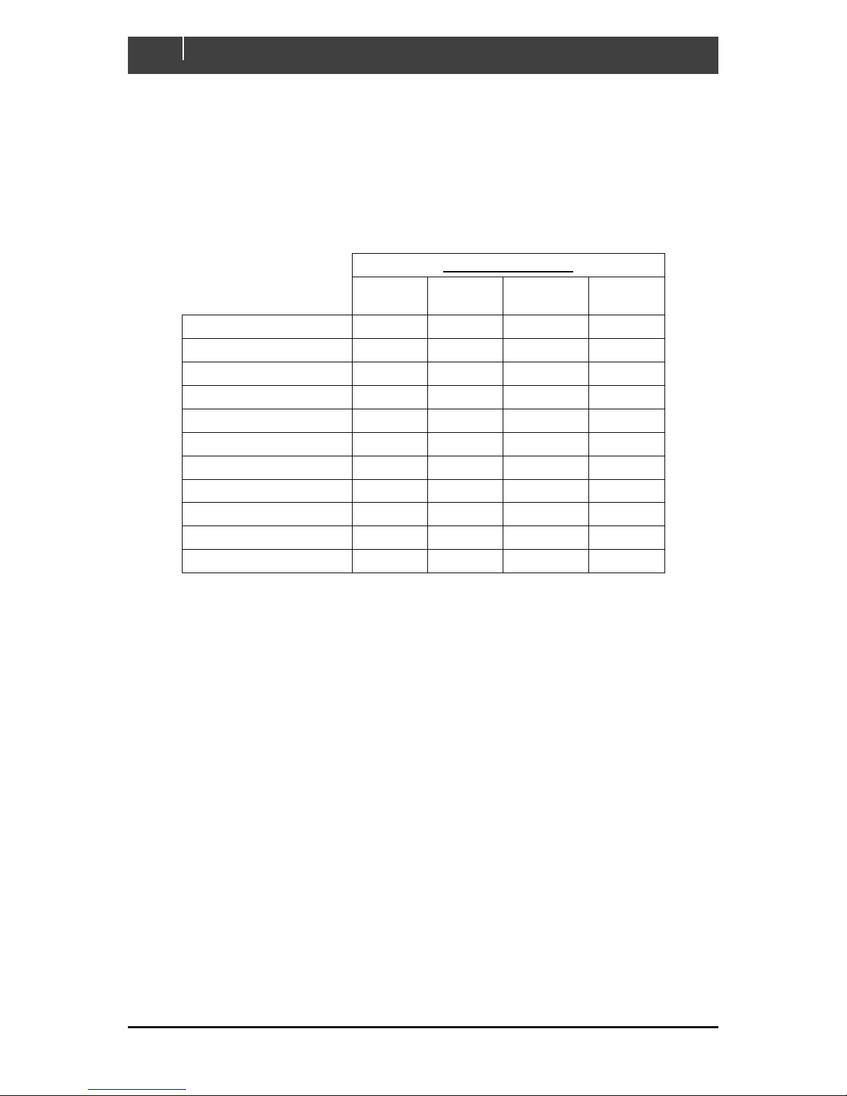
Below is an example which summarises the effect that selecting a mode has on the vessels systems.
The builder should supply a similar summary for each of the modes configured.
Modes Configuration
Systems
On
Day
Cruise
Night
Cruise
Systems
Off
Backlight Zone 1
On
On
On (30.0%)
Off
Cabin Lights
On
Off
On (2.0%)
Off
Charger
Not Used
Not Used
Not Used
Not Used
Courtesy Lights Blue
Off
Off
On
Off
Courtesy Lights White
On
On
Off
Off
Fan
Off
On
On
Off
Fresh Water Pump
On
On
On
Off
Galley Lights
On
Off
On (2.0%)
Off
Hatch Lifter
Not Used
Not Used
Not Used
Not Used
Navigation Lights
Off
Off
On
Off
Saloon Lights
On
On
On (2.0%)
Off
Figure 4. Modes Configuration Example
Page 14
EN / CZone Touch 5 User & Installation Manual
14
4.2.2 Control
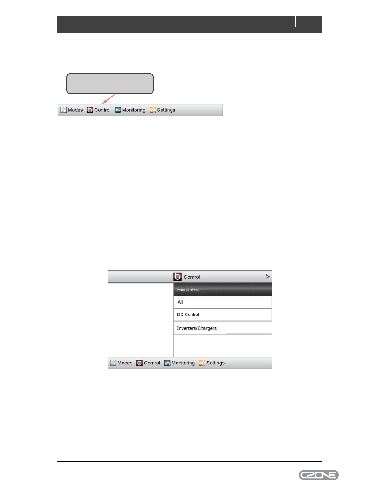
The main menu’s Control tab accesses all configured circuits on the CZone network.
Depending on which CZone modules are on the network, you may have one or more of the following
four circuit types:
DC Control - 12V or 24V DC loads, such as LED lights and fresh-water pumps.
AC Control - 120V or 230V AC loads, such as air conditioning and AC outlets.
AC Mains Control - a page for controlling/monitoring AC mains supplies (e.g. generator
and/or shore power). (Note: Requires a CZone AC Mains Interface.)
Inverters/Chargers - a page for controlling/monitoring Mastervolt Inverter/Chargers.
All AC and DC circuit types are accessible through the All circuit category. Circuits may also be
assigned a group category such as Lights or Pumps which allows circuits on large systems to be
accessed quickly. There may also be a Favourites category which will be configured by the builder for
fast access to essential circuits.
Figure 5. Control Page
Click Control on the main menu
along the bottom of the screen
Page 15
15
EN / CZone Touch 5 User & Installation Manual
4.2.2.1 DC Control and AC Control Circuits
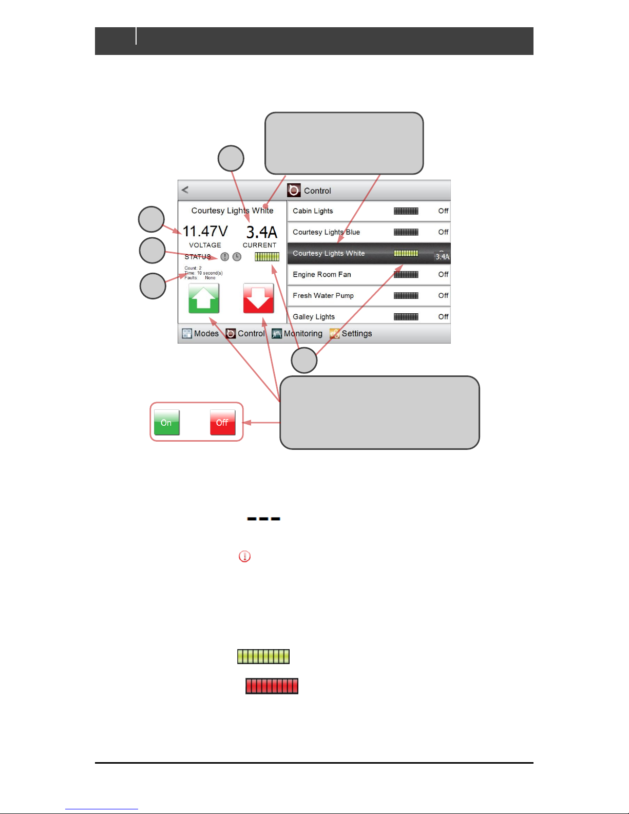
All DC Control and AC Control circuits behave in a similar way. An example is shown below:
A Current draw is tracked while the circuit is active, or shown as Off
B The voltage from the battery supplying the circuit (if configured) is tracked while the circuit
is active, or shown as
C The alarm status is grey while the circuit is operating correctly. If an alarm is raised this
indicator changes to .
D On Count tracks the number of times the circuit has been activated.
On Time displays the aggregate time for which the circuit has been active.
Faults reports the most recent fault raised by the circuit, or None if it is operating
correctly.
E The status bars are dark while the circuit is inactive. When an on/off circuit is active, these
indicators change to . The example circuit is dimmable, so the number of lit
segments in each status bar tracks the circuit’s setting. When an alarm is raised, the
status bars change to
.
1 Click on the circuit you wish to
control. Highlighting shifts to
Courtesy Lights White and the
display pane tracks its status
A
B C D
E
2 This circuit is dimmable, so you can
press and hold the up or down button
then release it at the desired brightness.
For an on/off circuit the up/down buttons
are replaced with On/Off buttons
Page 16
EN / CZone Touch 5 User & Installation Manual
16
4.2.3 Monitoring
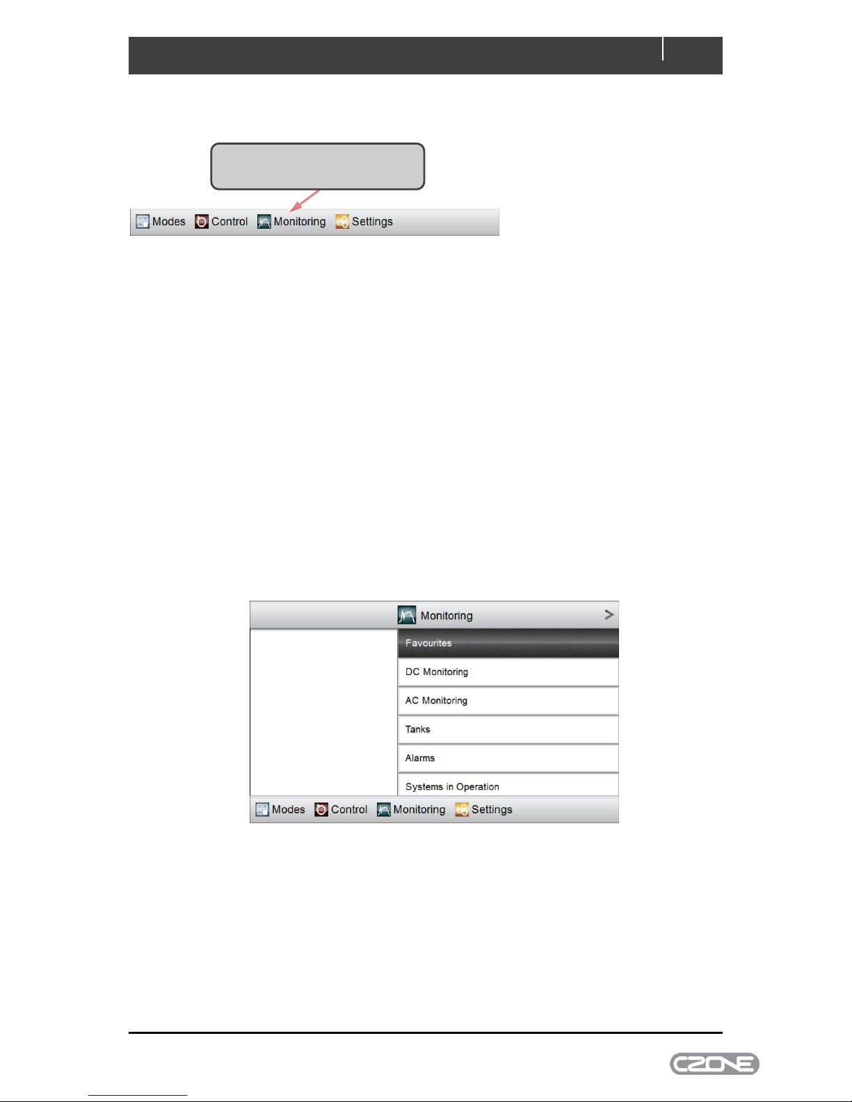
The main menu’s Monitoring tab accesses all configured metering on the CZone network.
Depending on which CZone modules are on the vessel, you may have one or more of the following
five monitoring types:
DC Monitoring - 12V or 24V supplies such as house or starter batteries, and chargers
AC Monitoring - 120V or 230V AC sources, such as shore power supplies, on-board
generators and inverters
Tanks – levels for tanks such as fresh-water, fuel, black water or grey water
Alarms - Alarm history, and unacknowledged alarms at four severity levels: Warning,
Standard, Important and Critical
Systems in Operation - access to all configured circuits that are active, in the same
categories that appear under the Control menu.
There may also be a Favourites category which will be configured by the builder for fast access to
essential meters.
Figure 6. Monitoring Page
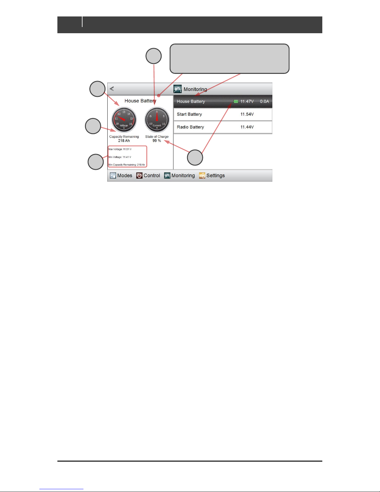
4.2.3.1 DC Monitoring
All DC Monitoring meters behave in the same way. An example is shown below:
Click Monitoring on the main menu
along the bottom of the screen
Page 17
17
EN / CZone Touch 5 User & Installation Manual
A An analogue gauge is mimicked to show the current draw
B Another gauge shows the voltage
C The calculated remaining capacity is shown, in amp-hours
D The calculated charge-state is shown, as a percentage of full charge and as the green portion
of a small icon resembling a cell
E The maximum and minimum recent states of the battery are reported.
Click on the DC device that you wish to
monitor. Highlighting shifts to the selected
device and the display pane tracks its status
A B C
D
E
Page 18
EN / CZone Touch 5 User & Installation Manual
18
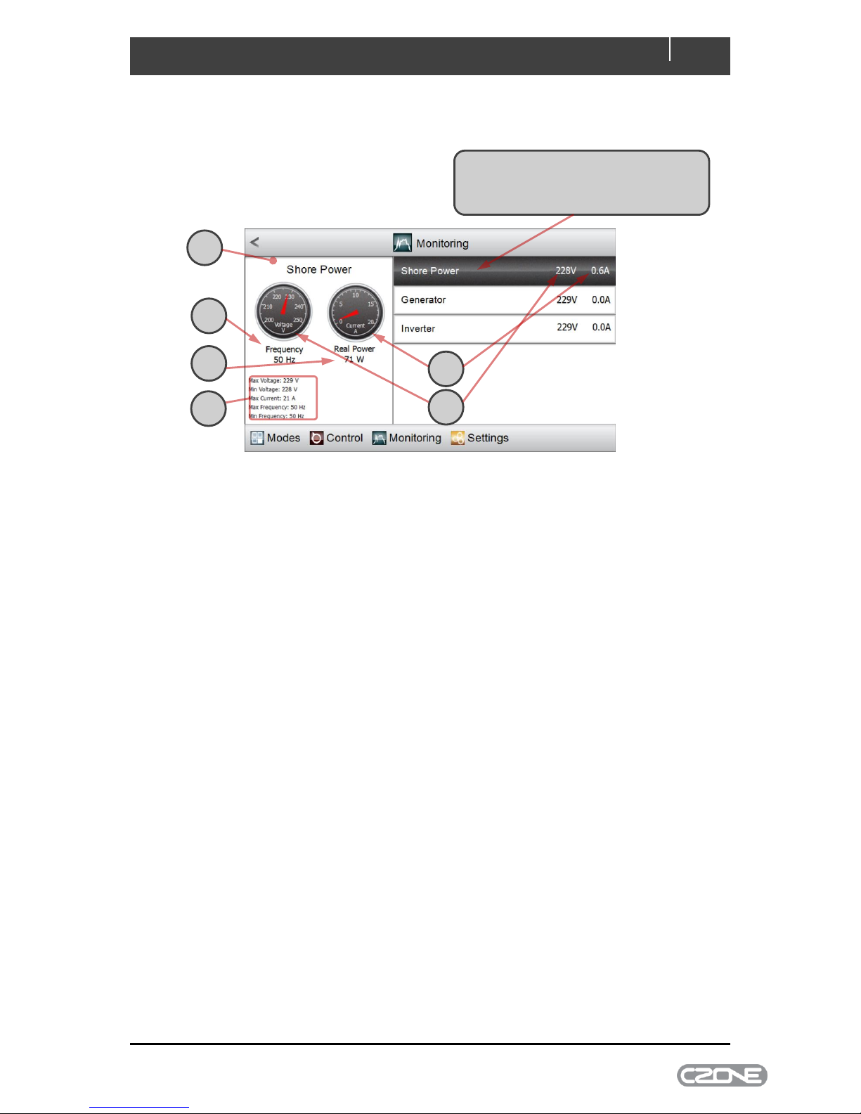
4.2.3.2 AC Monitoring
All AC Monitoring meters behave in the same way. An example is shown below:
A The status of the selected AC Mains source is detailed in the display panel
B The current drawn by all load groups supplied by the source is shown, to the right of the
highlighted name and using an analogue meter gauge
C The RMS voltage of the selected AC Mains source is shown, also in the highlighted region
and using an analogue meter gauge
D The frequency of the AC Mains source is shown
E The real power being supplied to all load groups supplied by the source is shown
F Worst-case recent performance of the selected source is shown, including:
maximum and minimum RMS voltages
maximum current draw by all supplied load groups
maximum and minimum supply frequency.
Click to highlight the AC source that you
wish to monitor. (In this example, only the
Shore Power source is supplying a load)
A B C
D E F
Page 19
19
EN / CZone Touch 5 User & Installation Manual
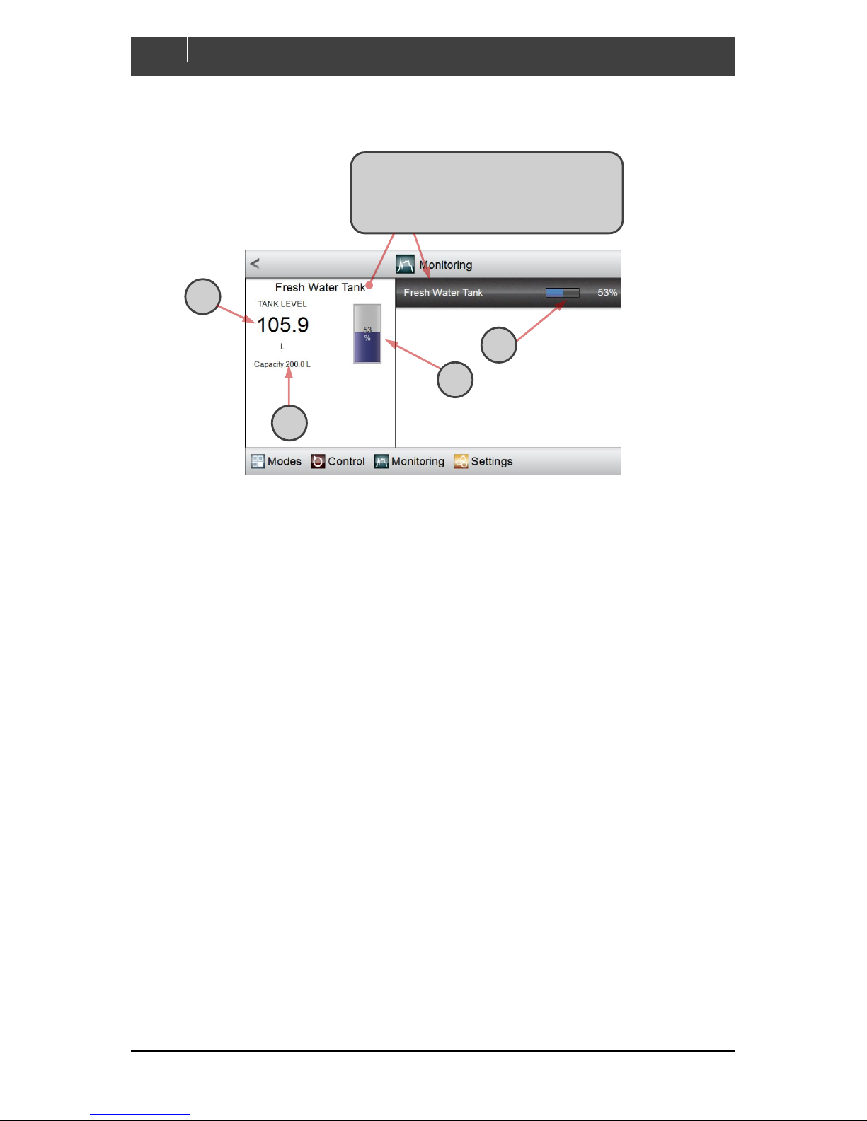
4.2.3.3 Tanks
All Tank monitoring meters behave in the same way. An example is shown below:
A The current level in the tank is displayed, using the configured units
B The tank’s level is reported in the highlighted section, as a percentage and as the blue portion
of a status bar
C In the display pane, a cylindrical tank mimic shows the tank level in blue and as a percentage
D The capacity of the tank is shown in the configured units.
Click on the tank that you wish to monitor. (In
this example, only the Fresh Water Tank is
configured.) The selected tank is highlighted
and the display pane tracks its status
A
D
C
B
Page 20
EN / CZone Touch 5 User & Installation Manual
20
4.2.3.4 Alarms
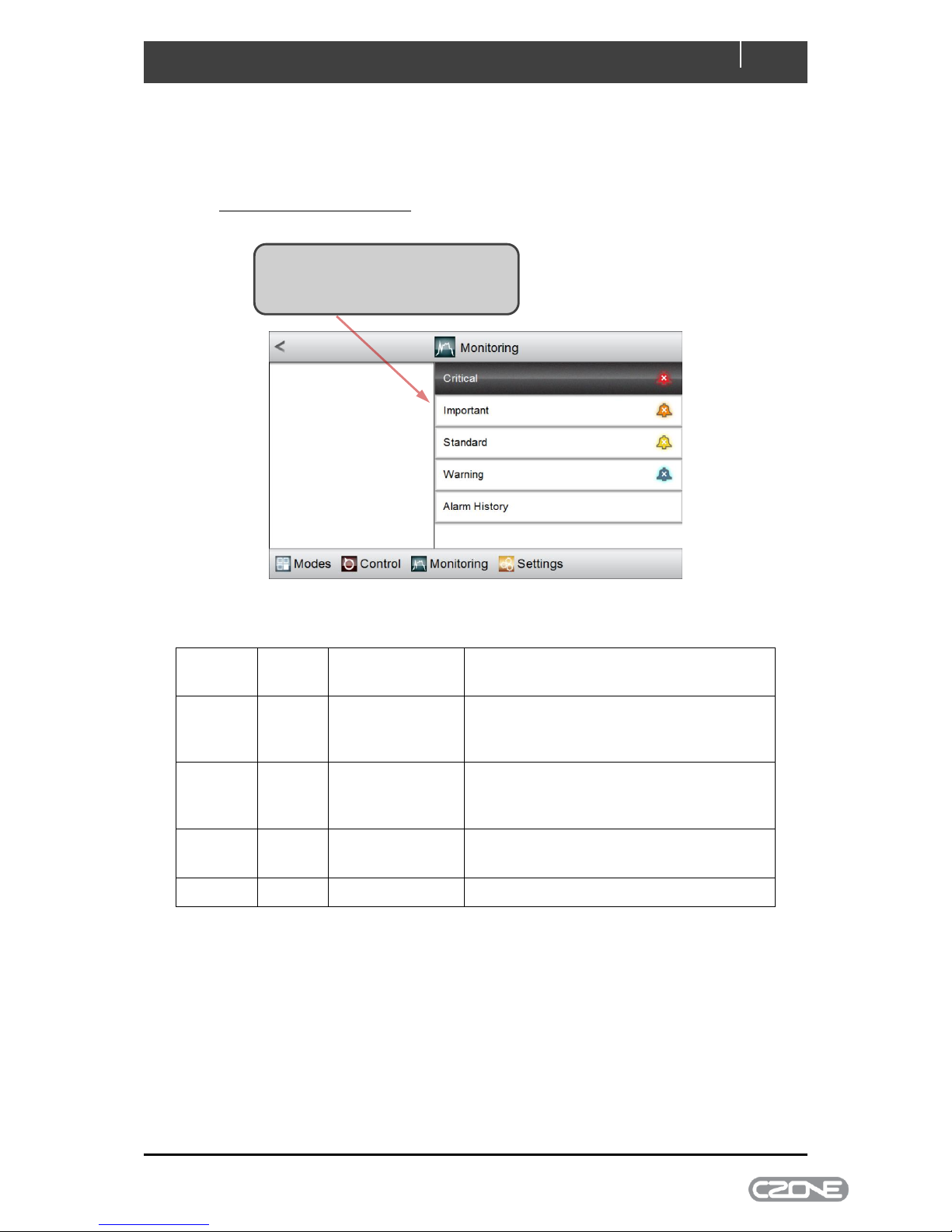
Alarm monitoring behaves in the same way for all levels of severity. On selecting Alarms from the
Monitoring home-page you can select historical alarms, or active alarms of any severity.
4.2.3.4.1 Alarms of a Selected Severity
Below is a list of the different CZone alarm severities and their behaviour:
Alarm
Level
Bell
Colour
Action on
Trigger
Additional Note
Critical
Red
Full-Screen
Dialog,
Audible Tone
Acknowledgement times out after 10 minutes
then re-alarms
Important
Orange
Full-Screen
Dialog,
Audible Tone
Acknowledgement times out after 10 minutes
Standard
Yellow
Full-Screen
Dialog
Full-screen dialogue disappears once alarm
is acknowledged
Warning
Blue
Bell Appears
Bell disappears once alarm is acknowledged
Figure 7. CZone Alarm Severity Definition
Click on the severity level that you wish
to monitor (Severity levels are matched
to coloured ‘bell’ icons on the right).
Page 21
21
EN / CZone Touch 5 User & Installation Manual
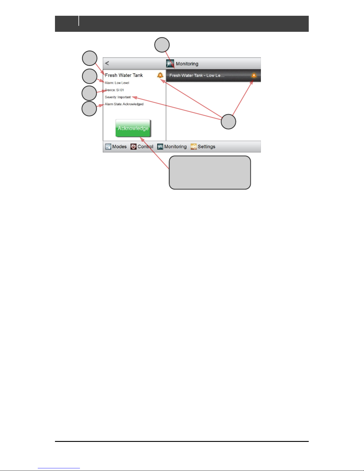
A A list of active alarms appears, all with the selected severity level. More-recent alarms are
listed first. (In this example, the Low Level alarm from the Fresh Water Tank is the only
important alarm currently active.)
B The name of the input that raised the alarm is shown in the display pane
C The name of the alarm is displayed
D The CZone module that detected the alarm is shown
E The alarm state is shown: either Enabled or Acknowledged.
F The alarm severity is described in words, and with a bell-shaped icon of the appropriate
colour.
A
B
C
D E F
Click the Acknowledge button
to disable an alarm if its state
is Enabled (Its entry will
remain in the Alarm History).
Page 22
EN / CZone Touch 5 User & Installation Manual
22
4.2.3.4.2 Alarm History
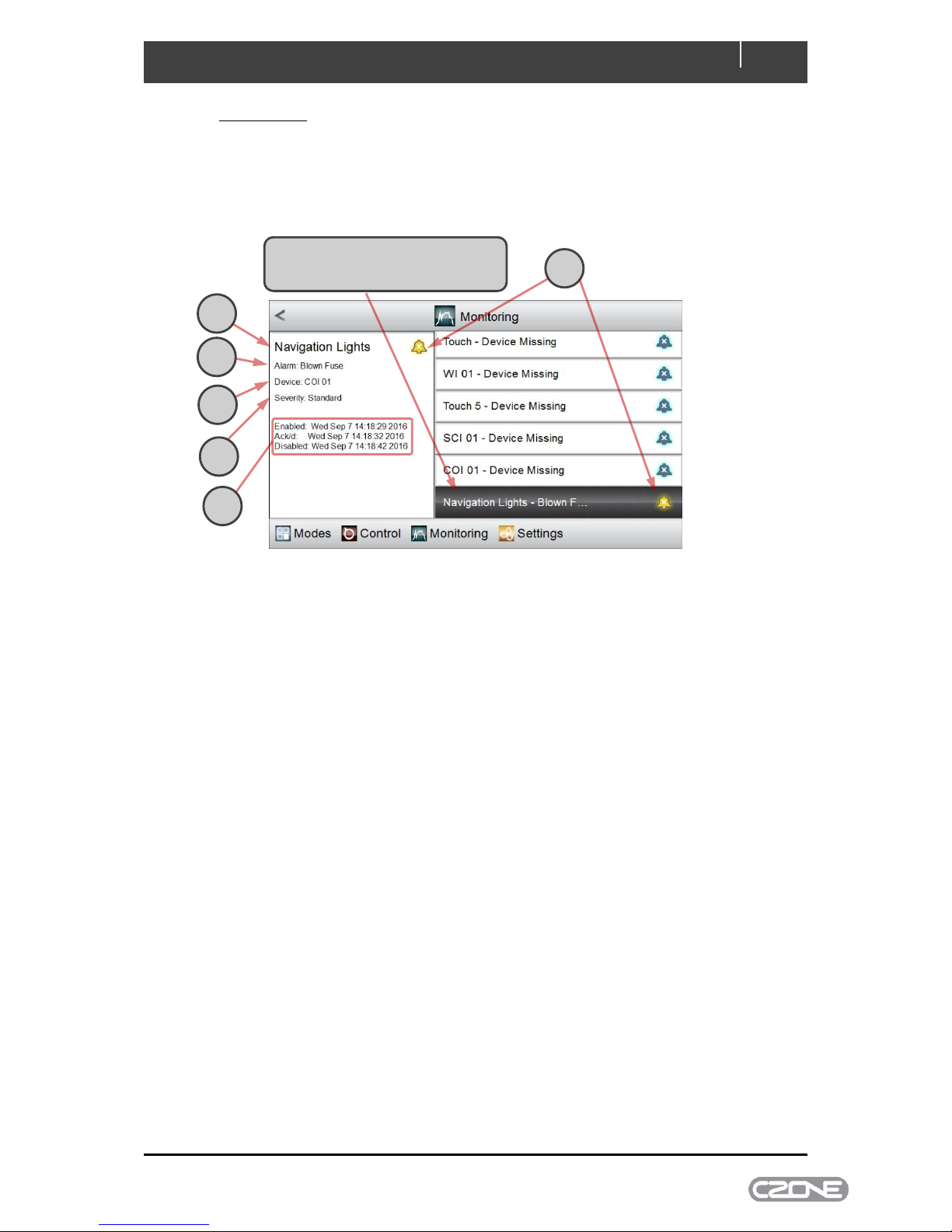
Selecting Alarm History from the Monitoring > Alarms page displays the most recent alarms (up to
100). Alarms are listed according to when they were raised, with the most recent first. Alarm history
includes all alarms above Warning severity by default. The minimum severity saved in history can be
changed from the Settings > System > Alarm Log Severity page.
A The alarm severity is indicated with a bell-shaped icon of the appropriate colour
B The name of the input that raised the alarm is displayed
C The name of the alarm is shown
D The CZone module that detected the alarm is shown
E The severity of the alarm is reported in words
F The date/time stamps for the alarm are:
when it was raised (i.e. enabled)
when it was acknowledged
when it was cancelled (i.e. disabled).
4.2.3.5 Systems in Operation
The Systems in Operation page lists all circuit categories that are configured for the vessel: for
example Pumps, Fans/Ventilation, and Lighting. Selecting any category displays all active circuits in
that category; alternatively, selecting All displays all active circuits regardless of their category.
Systems in operation behave exactly as DC or AC Control circuits: selecting a circuit displays its
status and allows the circuit to be controlled.
Click to highlight the historical alarm
that you wish to see in detail
A B C D E
F
Page 23
23
EN / CZone Touch 5 User & Installation Manual
4.2.4 Settings
The Settings tab lets you query and change various parameters of the Touch 5, including:
measurement units (gallons, litres, etc.); the network configuration; date/time and others.
4.3 Updating Software
To keep the Touch 5 up to date with the latest software refer to www.czone.net . It is recommended
to update the entire CZone system when updating the Touch 5 to ensure the system operates
correctly. The Touch 5 can be updated via the microSD card slot, see process below:
4.3.1 Checking Current Software Version
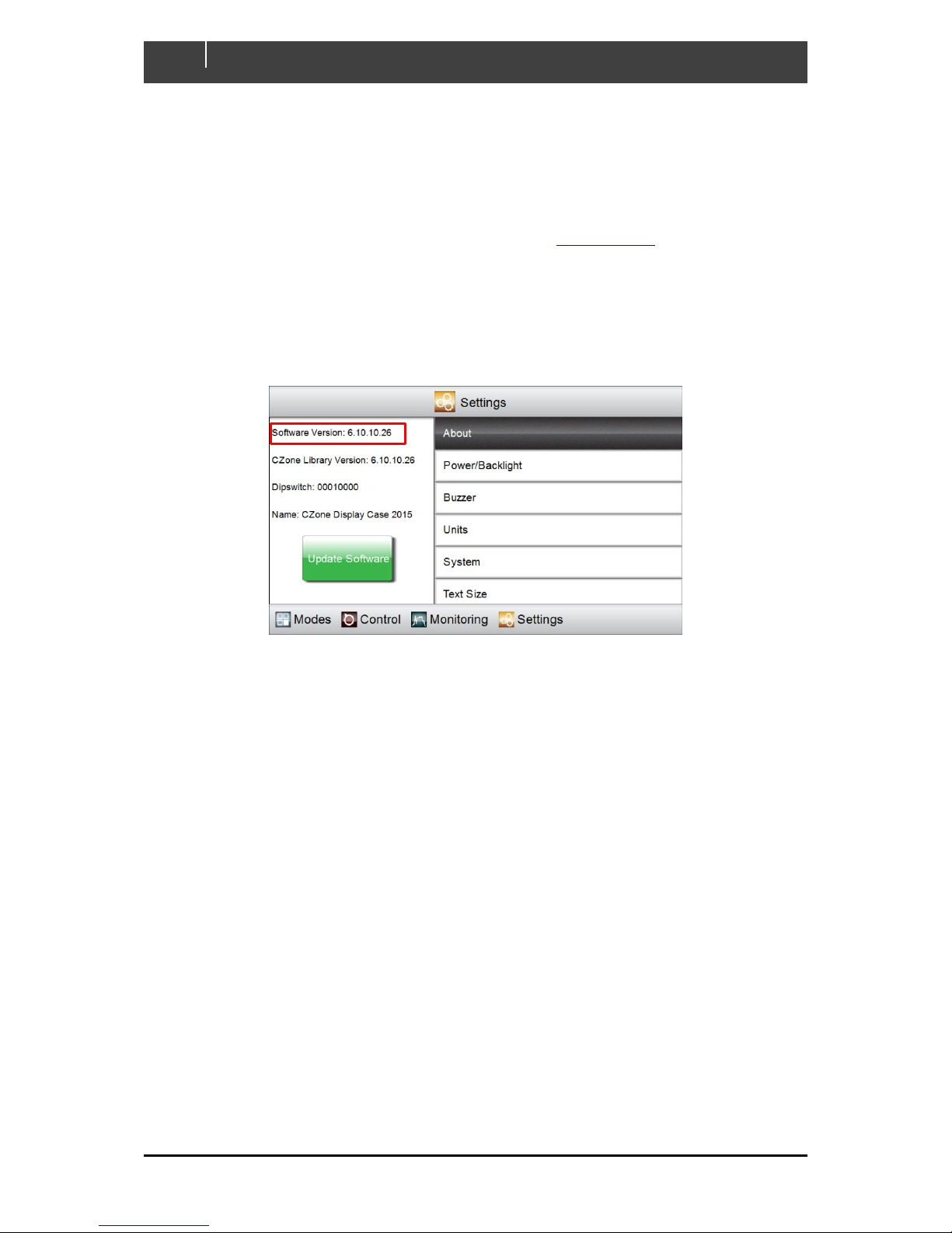
To check the current software version on the Touch 5 go to Settings > About
The current software version is listed at the top of the page. To install a newer version follow the
below steps
4.3.2 Updating Software via microSD
1. Copy the Touch 5 firmware file (extension .upd) on the root directory of a microSD card.
2. Insert the microSD card in the card reader slot of the Touch 5 (refer to chapter 1.2.4 for
process).
3. Press the ‘Update Software’ button on the Settings > About page and press ‘Yes’ when
prompted (Alternatively, the update will start if the power on the Touch 5 is cycled).
4. The display will reboot and start installing the new software, this process may take a few
minutes.
5. When complete the display will boot up to the main screen. Go to Settings > About to confirm
the new Software Version.
Page 24
EN / CZone Touch 5 User & Installation Manual
24
4.4 Wireless Interface Setup
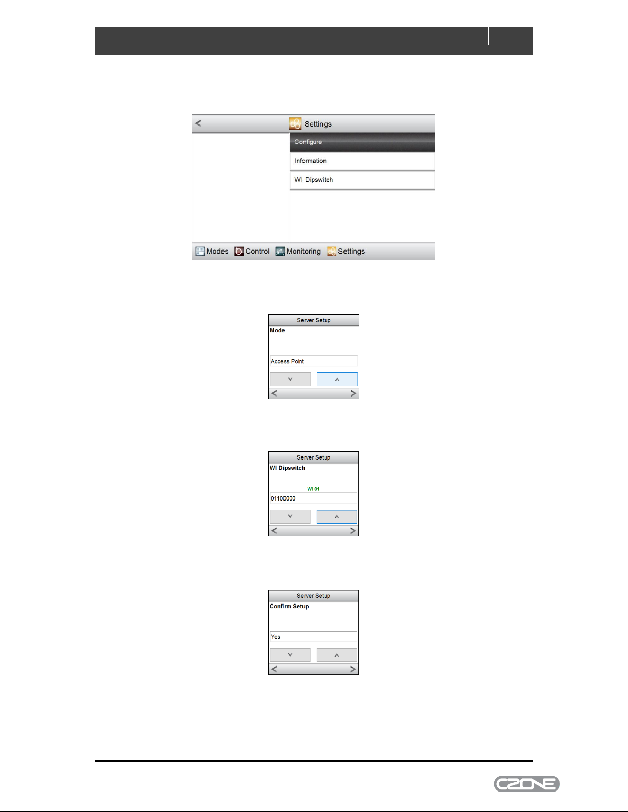
To configure the Wireless Interface on the Touch 5 go to Settings > System > Server > Configure
Select the Server Mode (Access Point, Client Mode or Disabled), then press the right arrow (refer to
the Wireless Interface Setup Instructions for a definition of these server modes).
Select the WI Dipswitch then press the right arrow (the dipswitch should match what is configured in
the CZone Configuration)
Select Yes to confirm setup, then press the right arrow
The Wireless Interface is now configured.
Page 25
25
EN / CZone Touch 5 User & Installation Manual
4.5 Connecting iPad to Touch 5
Follow the below steps to connect an iPad to the Touch 5 via WiFi. Before proceeding a WI package
must be present on the Touch 5’s CZone server, this package contains the custom favourite page
settings and images. Refer to the Wireless Interface Setup Instructions for this process.
1. Download the CZone App on your iPad from the Apple App Store
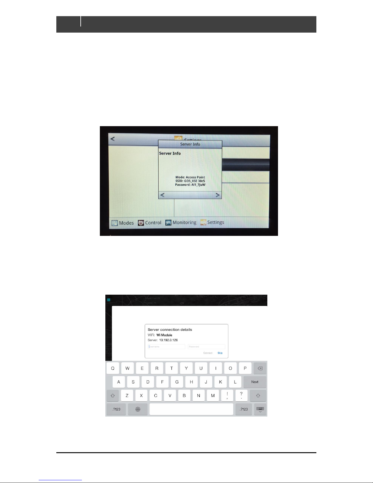
2. On the Touch 5 Go to Settings > System > Server > Information
3. The following screen will show the Touch 5’s unique SSID and Password
4. Go to Settings > WiFi on your iPad, select the SSID and enter the Password as shown on the
Touch 5 Server Info
5. Once your iPad has successfully connected open the CZone App
6. Enter the server username and password and press connect
Page 26
EN / CZone Touch 5 User & Installation Manual
26
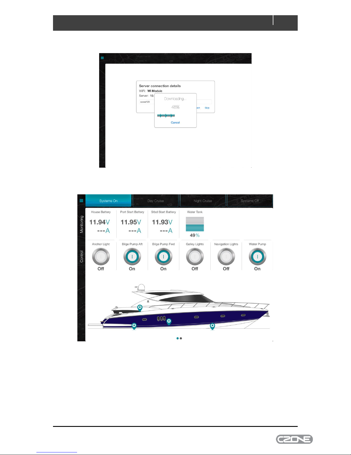
7. The Wireless package will start downloading
8. Once the download is complete you will see the favourites page of the configured system.
Figure 8. CZone iPad App Favourites Page Example
Page 27
27
EN / CZone Touch 5 User & Installation Manual
5 Specifications
5.1 Technical Specifications
Model
Touch 5
Article number
80-911-0124-00
Casing
PCB/ABS
Display Type
WVGA Colour TFT LCD
Display Resolution
480 x 800 pixels (H x W)
Screen Brightness
1200 nits
Operating
Temperature
-15°C to +55°C (+5°F to +131°F )
Water Ingress
IPX6 and 7
Operating Voltage
10 – 17V DC
Power Consumption
900mA @ 13.5V
Processor
iMX61 single core
Weight (excluding
mounting hardware)
526 grams (1.16lbs)
Conformity
CE, C-Tick
5.2 Dimensions
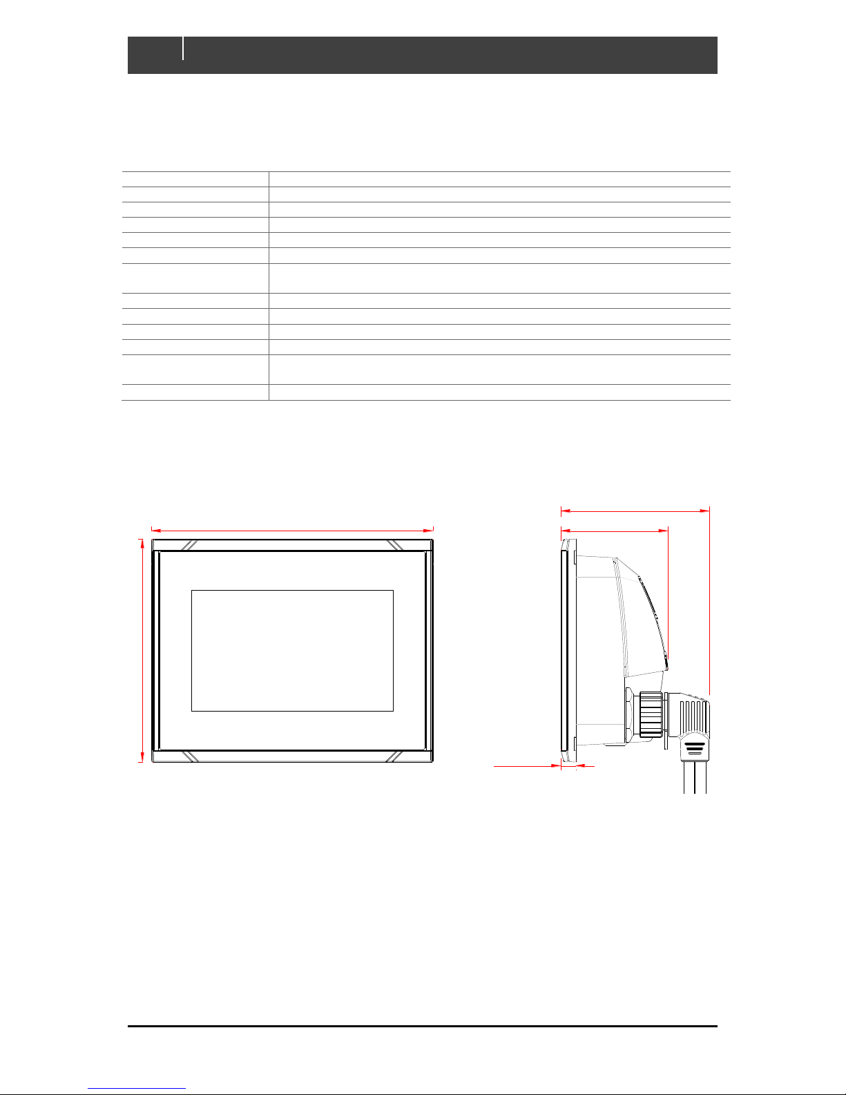
Figure 9. Dimensions
58 [2 1/4"]
80 [3 3/16"]
8 [5/16"]
152 [6"]
120 [4 3/4"]
Page 28

EN / CZone Touch 5 User & Installation Manual
28
6 EC DECLARATION OF CONFORMITY
We,
Power Products LLC
Mailing Address:
BEP Marine LTD
PO Box 101-739 NSMC
Auckland 0632, New Zealand
Street Address:
42 Apollo Drive
Rosedale,
Auckland, 0632, New Zealand
Declare under our sole responsibility that the following product to which this declaration relates is in
conformity with the requirements of EU directive 1999/5/EC R&TTE (Radio and Telecommunications
Terminal Equipment) and satisfies all the technical regulations applicable:-
Type : CZone, Touch 5 Display
Brand : BEP Marine
Model : CZONE TOUCH 5 KIT
P/N 80-911-0124-00
To which this declaration related, is in conformity with the following standards or other normative
documents:EMC : EN 60945:2002
EN 301 489-1 V1.9.2
Health & Safety : EN 60950-1:2006
Radio : EN 300 328 V1.9.1
EN 300 440-2 V1.1.1
Albany, New Zealand, 15 March 2017
Mark Griffith
R & D Manager
BEP Marine Ltd
42 Apollo Drive
Rosedale, Auckland
New Zealand
Tel:64-9-415-7261
 Loading...