

Page 1
Product description:
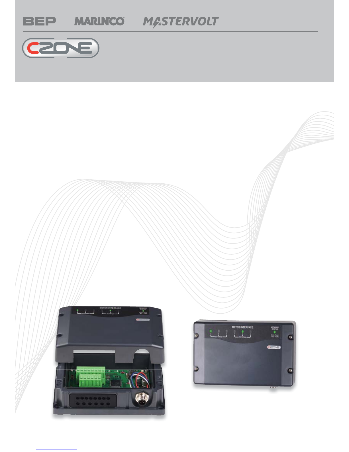
The Meter Interface is designed to accept multiple inputs from AC current and voltage transformers as well as DC voltage inputs and current
inputs from shunts The MI processes the information from these inputs and broadcasts it onto the CZone bus
AC
• 3 x AC voltage inputs (multi voltage)
• 2 x AC current inputs
• Calculates true RMS power
• Ignition protected
• IPX5 water ingress protection
DC
• 3 x DC voltage inputs (multi voltage)
• 2 x DC current inputs
• Calculates battery capacity as Ampere hours and percentage
charge remaining
• Resolution for current metering down to 0.1A
• Dimensions:
H 100mm (3”29/32) x W156mm (6”3/32) x D 42mm (1”5/8)
• Weight: 281g
• Note: High and low alarm levels can be set for all inputs
EMC ratings:
• IEC EN 60945
• IEC EN 61000
• FCC Class B
• ISO 7637 - 1 (12V Passenger cars and light commercial vehicles
with nominal 12 V supply voltage - Electrical transient conduction
along supply lines only)
• ISO 7637 - 2 (24V Commercial vehicles with nominal 24 V supply
voltage - Electrical transient conduction along supply lines only)
• IEC Standards for indirect lighting strikes
MI features:
Meter Interface (MI)
For more information contact BEP | ph: +64 9 415 7261 | email: enquiries@bepmarine.com | www.bepmarine.com
Page 2

For more information contact BEP | ph: +64 9 415 7261 | email: enquiries@bepmarine.com | www.bepmarine.com
LED Flash Codes
Channel status indicators Network Status indicator
Network Status Indicator
• Extinguished = Network power disconnected
• Green = Network power connected
• Red = Network traffi c
Channel Status Indicators
Page 3

Connections
Electrical Connections DC
BATTERY
-
+
ONE
STARTER
TWO
+
BATTERY
-
ENGINEBATTERY
SWITCH
SWITCH
BATTERY
1AMP FUSE
1AMP FUSE
450A 50mV
SHUNT
PUMP
BILGE
HORN
WIPER
BUS
BAR
BUS BAR
NEGATIVE
TWISTED PAIR
OUTPUT
INTERFACE
ALT 1
ALT 2
DC voltage positive input 2
DC voltage positive input 1
DC current 2 Shunt input 2 (LOAD)
DC current 2 Shunt input 1 (BATT)
DC current 1 Shunt input 2 (LOAD)
DC current 1 Shunt input 1 (BATT)
8 Way, DC
DC Negative
DC voltage positive input 3
(BATT) (LOAD)
NMEA 2000
NETWORK
BREAKER
CIRCUIT
Electrical Connections AC
V1
NEUTRAL
SHORE
PHASE
V2
V3
C
P
N
N
P
N
P
AC1
AC2
AC3
GENERATOR
NEUTRAL
PHASE
AC LOAD
GROUP
POWER
TRANSFER
SWITCH
1A FUSE
1A FUSE
1A FUSE
BEP PART # AC-VSEN-Z
Transformer common
AC Voltage input 3 (from transformer)
AC Voltage input 2 (from transformer)
AC Current input 2 (from transformer)
AC Voltage input 1 (from transformer)
AC Current input 1 (from transformer)
NMEA 2000
NETWORK
Page 4

Labelling
For more information contact BEP | ph: +64 9 415 7261 | email: enquiries@bepmarine.com | www.bepmarine.com
Connections/LED fl ash code label
This label is located on the inside of the front lid of the unit, it shows the LED codes and electrical connections to the unit
Module Identifi cation and Dipswitch label
These labels allow easy identifi cation of each module whilst recording the dipswitch setting. These labels are to be fi tted to the cover and to the
module (this prevents covers being swapped). To record the module type and dipswitch settings use a permanent marker and strike through
the applicable boxes (a strike through on a dipswitch box indicates that switch is on).
Page 5

Installation Guidelines
For more information contact BEP | ph: +64 9 415 7261 | email: enquiries@bepmarine.com | www.bepmarine.com
Ensure the modules are installed vertically with the cables exiting downwards
All seals and cable glands must be fi tted including blanking plugs inserted in any unused positions.
Ensure all labels are fi tted and correct
Dimensions
 Loading...