

Czar PP-8300, PP-8500 User Manual

®Copyright 2015 July All Rights Reserved Version 1.0
The information contained in this document is subject to change without notice. We make no warranty of any
kind with regard to this material, including, but not limited to, the implied warranties of merchantability
and fitness for a particular purpose. We shall not be liable for errors contained herein or for incidental
or consequential damages in connection with the furnishing, performance, or use of this material.
This document contains proprietary information that is protected by copy right. All rights are reserved. No part of
this document may be photocopied, reproduced or translated to another language without the prior
written consent of the manufacturer.
TRADEMARK
Intel®, Pentium® and MMX are registered trademarks of Intel® Corporation. Microsoft® and Windows® are
registered trademarks of Microsoft Corporation.
Always high- speed! absolutely desirable

Main Board
CPU
PP-8500-15 Support IVY & Sandy Bridge Intel® Core i5 Dual Cores CPU
PP-8300-15
Support IVY & Sandy Bridge Intel® Core i3 Dual Cores CPU
Chipset
Intel® HM76 Express Chipset
System Memory
2x SO-DIMM (204pin) Slot, DDR3 1333 MHz, Max 8GB
Graphic Memory
Intel® HD 4000 Series Graphics
LCD Panel
PP-8500 -15 / PP8300 -15
Panel Size 15”
Maximum Resolution 1024 x 768
Brightness 250 cd/m1
Contrast Ratio 700 : 1
Response Time 16 ms
View Angles (H/V) 150 / 120
Touch Panel Five Wires Resistive Touch or Projected Capacitive Touch
Storage
HDD 2.5” SATAIII /SATAIII interface x 2
Expansion
Socket One Mini-PCIE or One Msata II
Power
Power Adaptor Input AC 100-240V 2.5A 50/60Hz, Output DC 12V 6.66A
I / O
USB Four USB 2.0, Two USB 3.0
Serial Four COM ports with DB-9 Connector
COM1, COM2 with 0V / 5V / 12V power selectable
COM3, COM4 with 0V / 5V / 12V power selectable
LAN One Realtek 8111F Gigabit Fast Ethernet controllers
2nd VGA Output One 15 Pin VGA Port
PS/2 One
Audio One Earphone & One Microphone
1
1

Cash Drawer One RJ-11
Control/Indicator
Power Button One
LED Indicators Power (Red)
Optional Peripherals
Magnetic Card Reader ISO Track 1/2/3, USB interface
VFD customer display 20 x 2 characters, RS-232 interface
Dimensions
PP-8300-15 PP-8500-15
358(W) X 70(L) X 293(H) mm
PP-8300-T15 PP-8500-T15 358(W) X 223.9(L) X 309.6(H) mm
Environment
Operating Temperature 0°C ~ 40°C ( 32°F ~ 104°F )
Storage Temperature - 20°C ~ 60°C ( - 4°F ~ 140°F )
Operating Humidity 10% - 80% RH non condensing
Storage Humidity 10% - 80% RH non condensing
Model Number
PP-8500-X – SS IVY & Sandy Bridge Intel® Core i5 Dual Cores CPU
X : T --- Contain foot
SS : 15 --- 15" TFT LCD
PP-8300-X – SS IVY & Sandy Bridge Intel® Core i3 Dual Cores CPU
X : T --- Contain foot
SS : 15 --- 15" TFT LCD
2

If any item is missin g, pl ease con t act your sale agent i mmediat el y.
Tak e the system unit out from the carton. Remove the unit by carefully holding the foam inserts and remove slowly to protect
the system. The following items should be found in the carton:
1. CD that including all
driver and manual
2. The System
. Power Adaptor 4. AC Power Cord
2
3
Please un plug th e A C power of the adapter before opening an y part of the system. Sin ce t he
standby power is always on after the adapter is plugged in. It may cause permanen t damage to
your system when you open any part of i t .
3
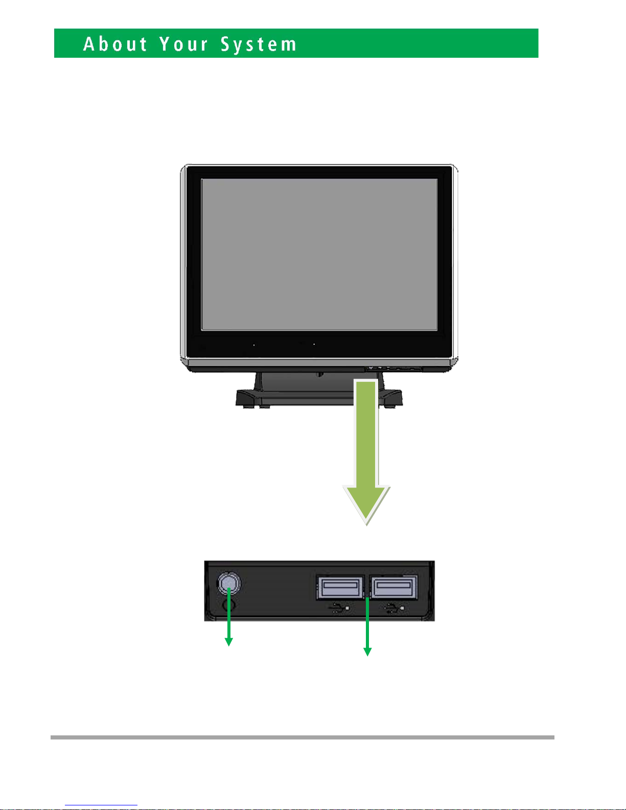
Front View
Power
Button
USB 2.0
4
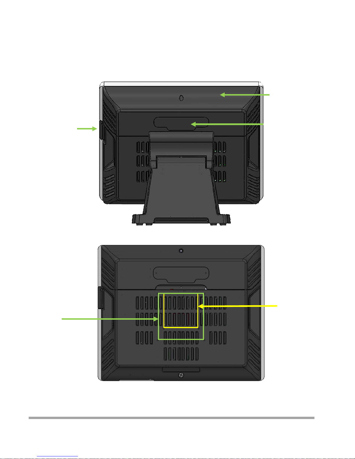
Rear View
Slot for installing
Magnetic Card
Rea der (op t ional)
Cable Cover
Slot for installing
Custo m Display
or Second Display
(optional)
VESA 75
VESA 100
5
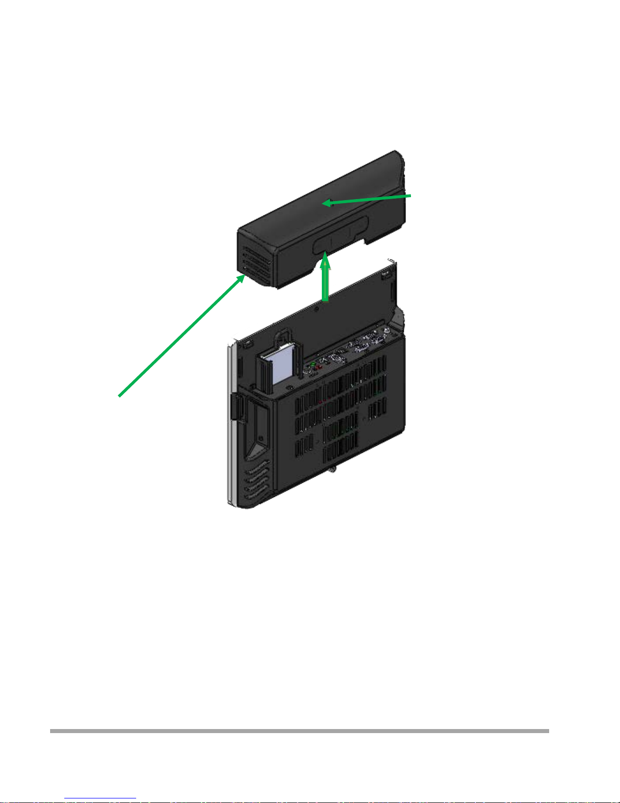
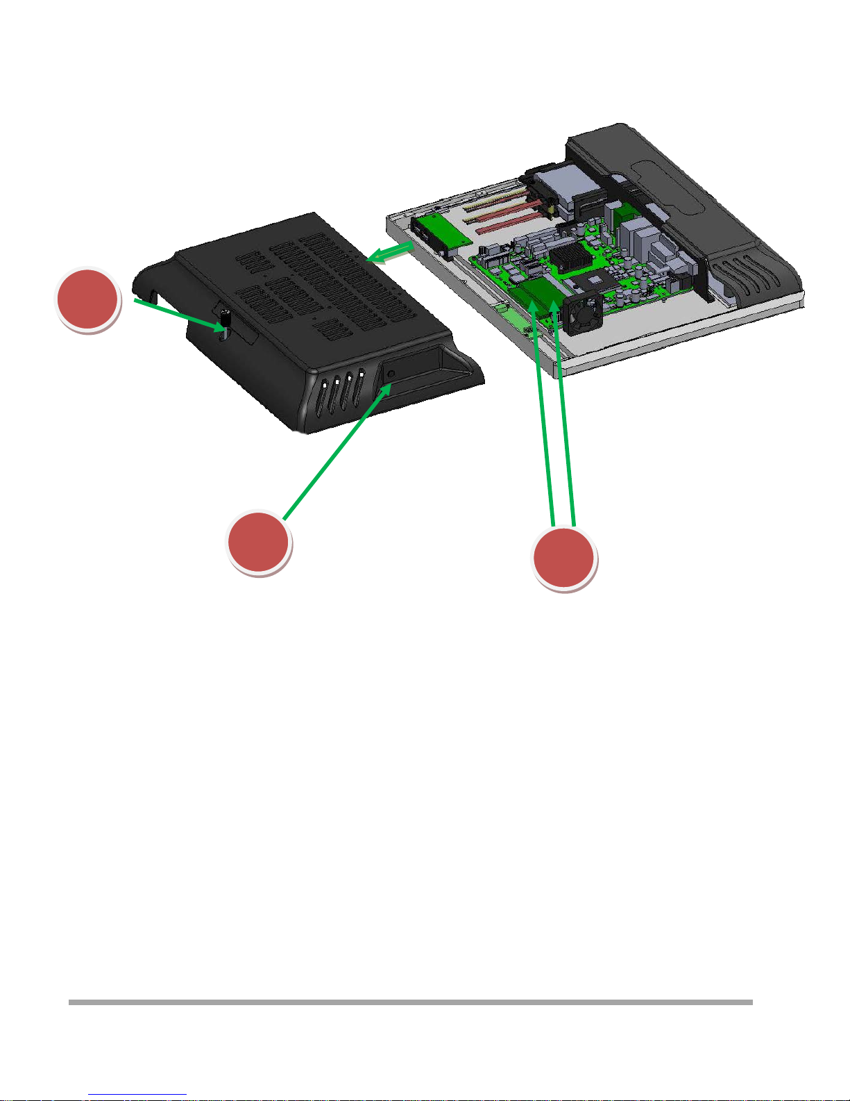
How to open the connector bezel
Please un plug th e A C power of the adapter before opening an y part of the system.
Since the standby power is always on after the adapter is pl ugged in.
It may cause permanent damage to your system w hen you open any part of it.
As illustrated in
the follow i ng,
Move these two sides upward
Release the screw
6
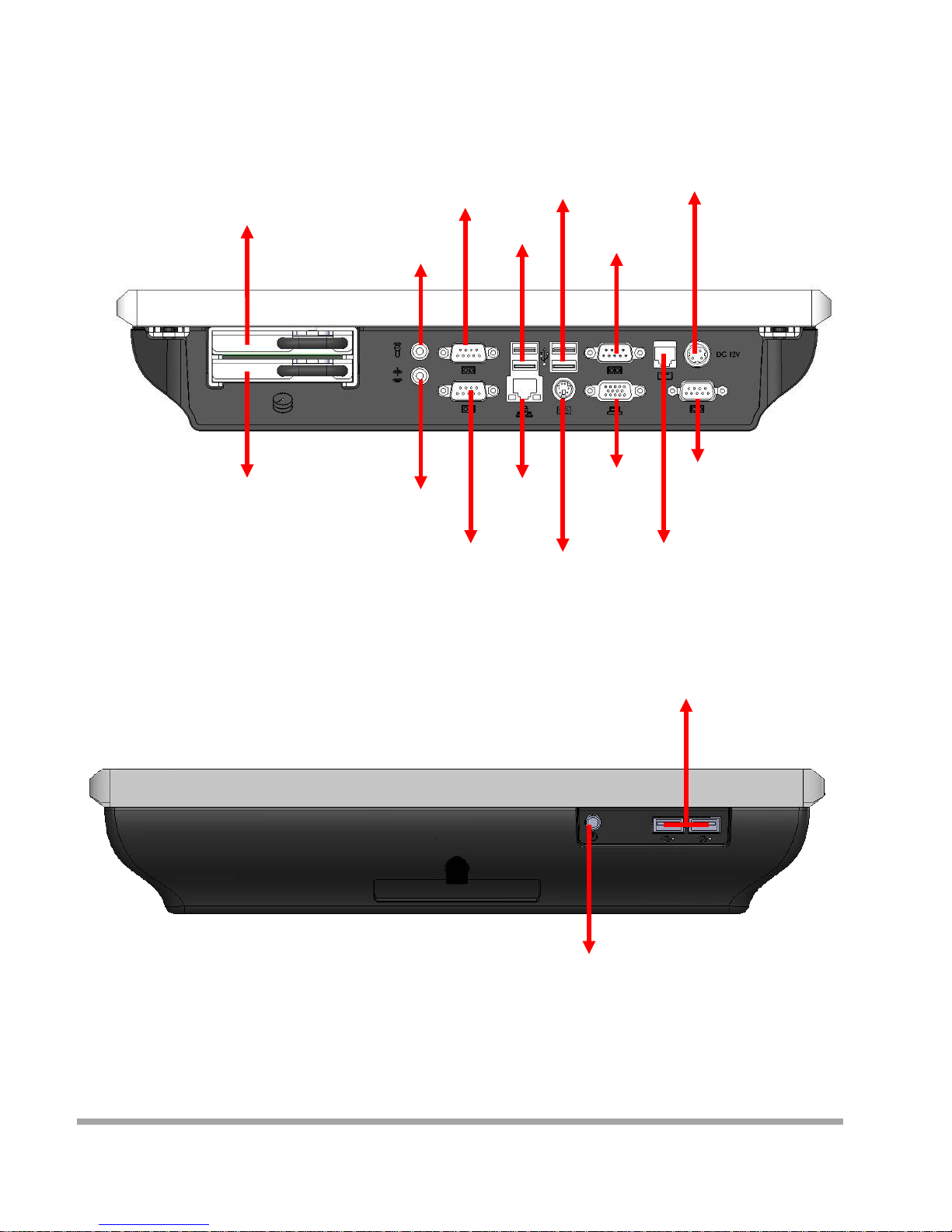
The connector panel
1. TOP of machine
2. Bottom of machine
Hard Disk 2
Power IN
Earphone
Microphone
USB 3.0
USB 2.0
VGA
LAN
COM3
COM4
P S /2
Power Button
USB 2.0
COM1
COM2
RJ11
Hard Disk 1
7
Please un plug th e A C power of the adapter before opening an y part of the system. Sin ce t he
standby power is always on after the adapter is plugged in. It may cause permanen t damage to
your system wh en you open any part of the system.
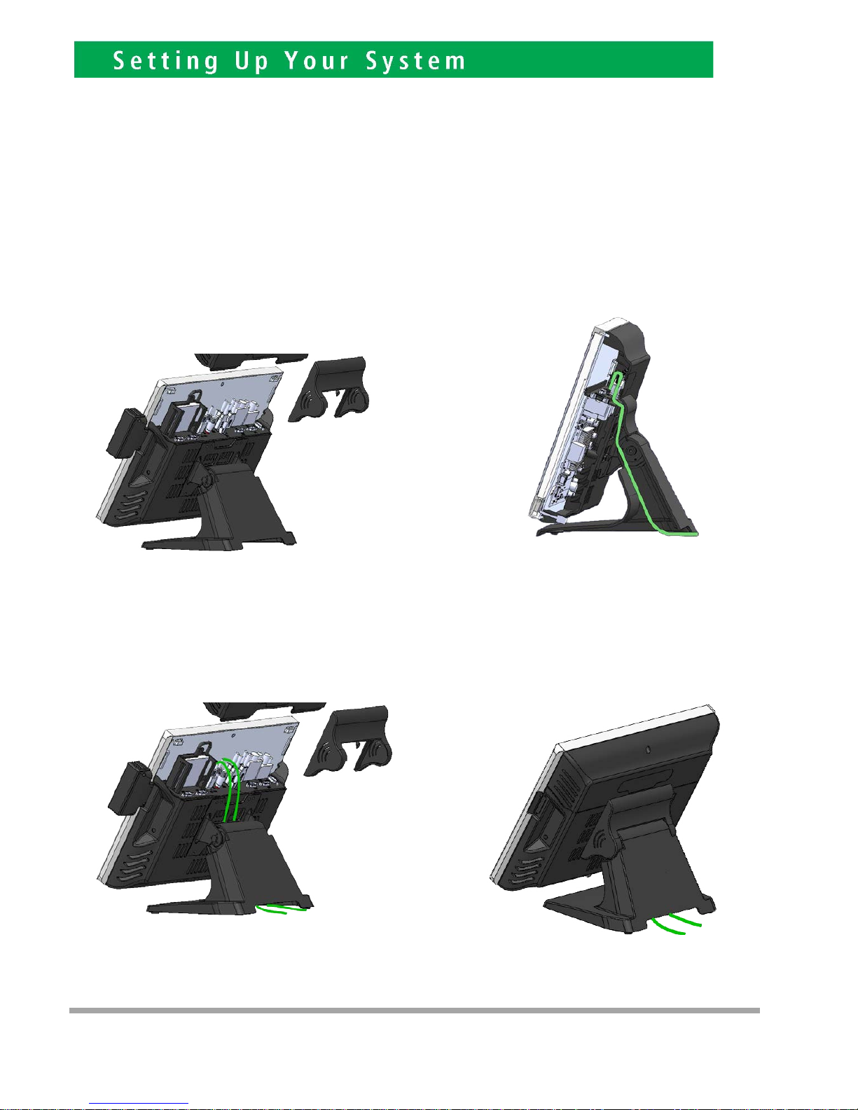
Installing Peripherals
To install the peripheral’s cables, please follow the method described below.
It will make the process much easier.
1. Open the Cable cover and Hinge cover 2. Follow the way of drawing to wiring
Plug in all the cable on the hots
3. Through the cable between HOST and FOOT
4
8
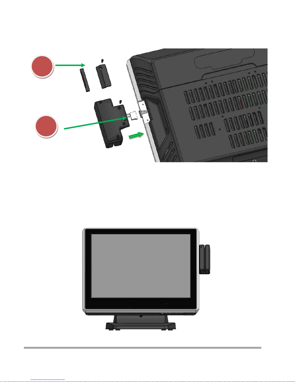
Installing Magnetic Card Reader (MSR)
1. Remove the rubber mat,Loosen the screw,and remove the MSR cover
2. Connected to the cable on the MSR and host,and lock two screws
1
2
9
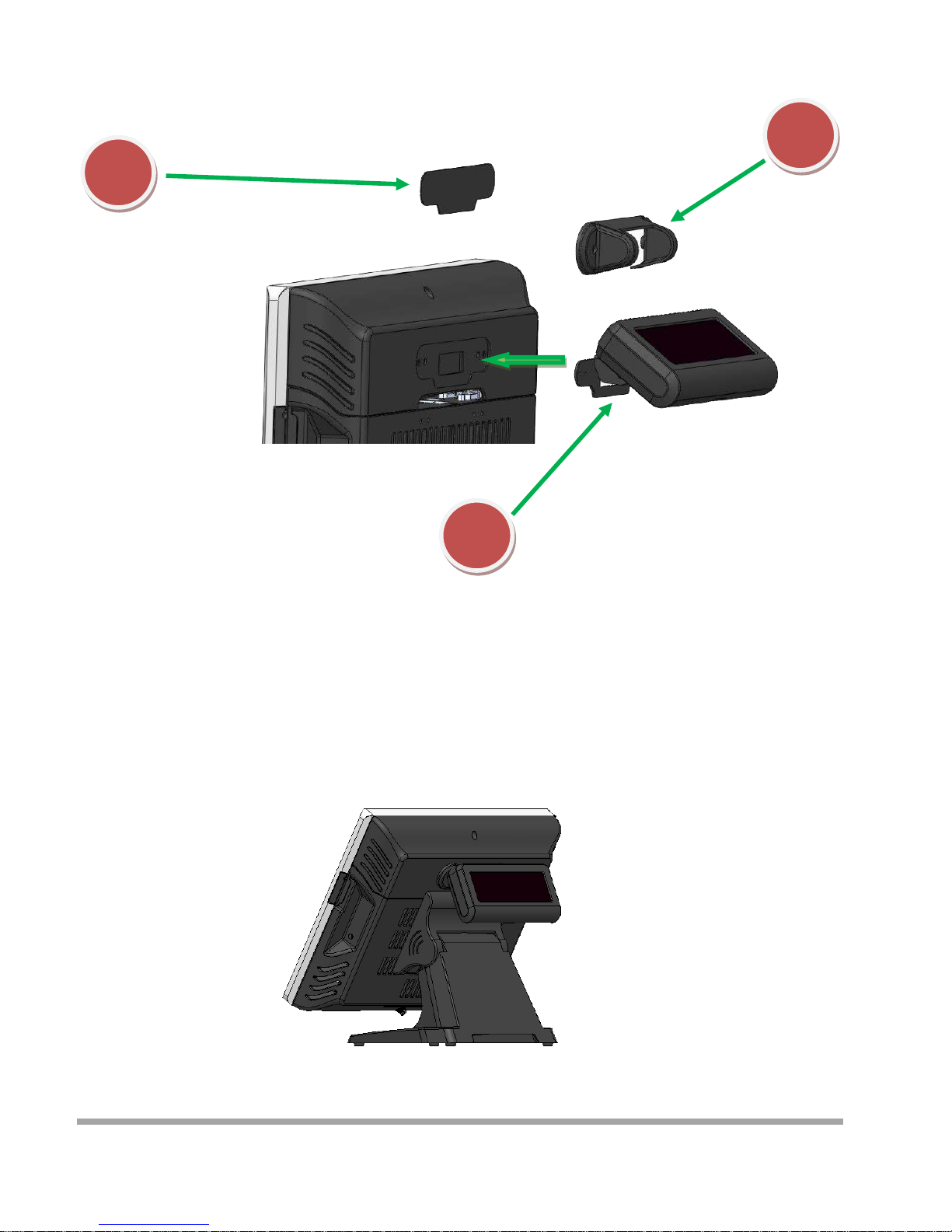
Installing Customer Display
1
2
3
1. Remove the metal bezel
2. Connected to the cable, lock the two screws on Cable Cover
3. Installation VFD cover and lock the two screws
10

Installing Second Display
1. Remove the metal bezel
2. Connected to the cable, lock the two screws on Cable Cover
3. Installation VFD cover and lock the two screws
1
2
3
11
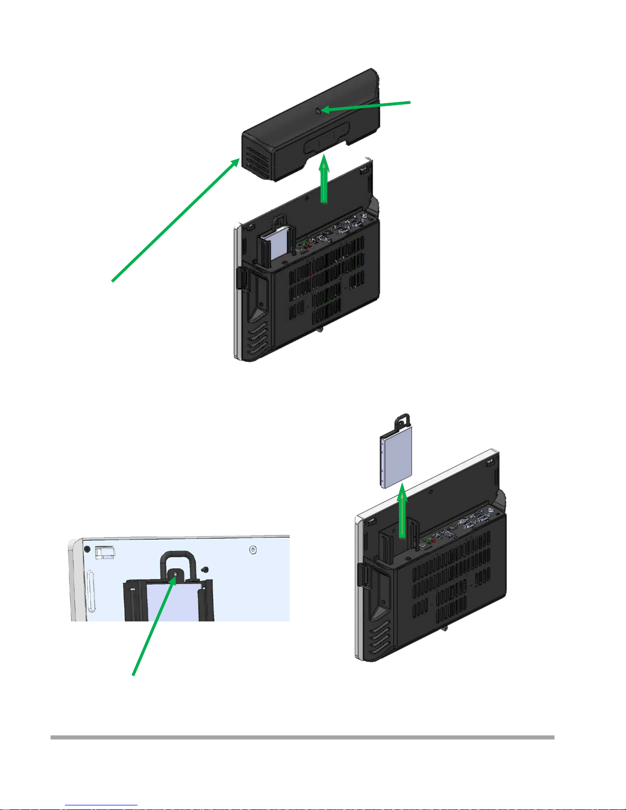
Replace and Installing Hard Disk
1. Release the screw
4. Grab the h andle and pull up or down
Remove or Installation Hard disk
2. Move these two side s upward
3. Release the screw
12
Replace and Installing Memory
1
2
1. Release the screw
2. Grasp the both sides , and pulled down the back cover
3. Replace or Installing Memory
3
13
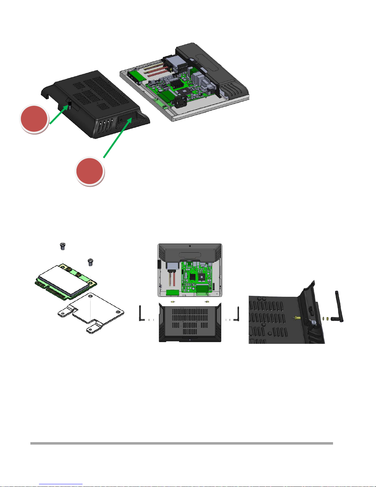
Installing WIFI Card and Antenna
1
2
1. Release the screw
2. Grasp the both sides , and pulled down the back cover
3. Install WIFI Card
Lock 2 screws
4. Remove the plastic pad on the both sides
of the Main cover
5. Inst all Antenna
14
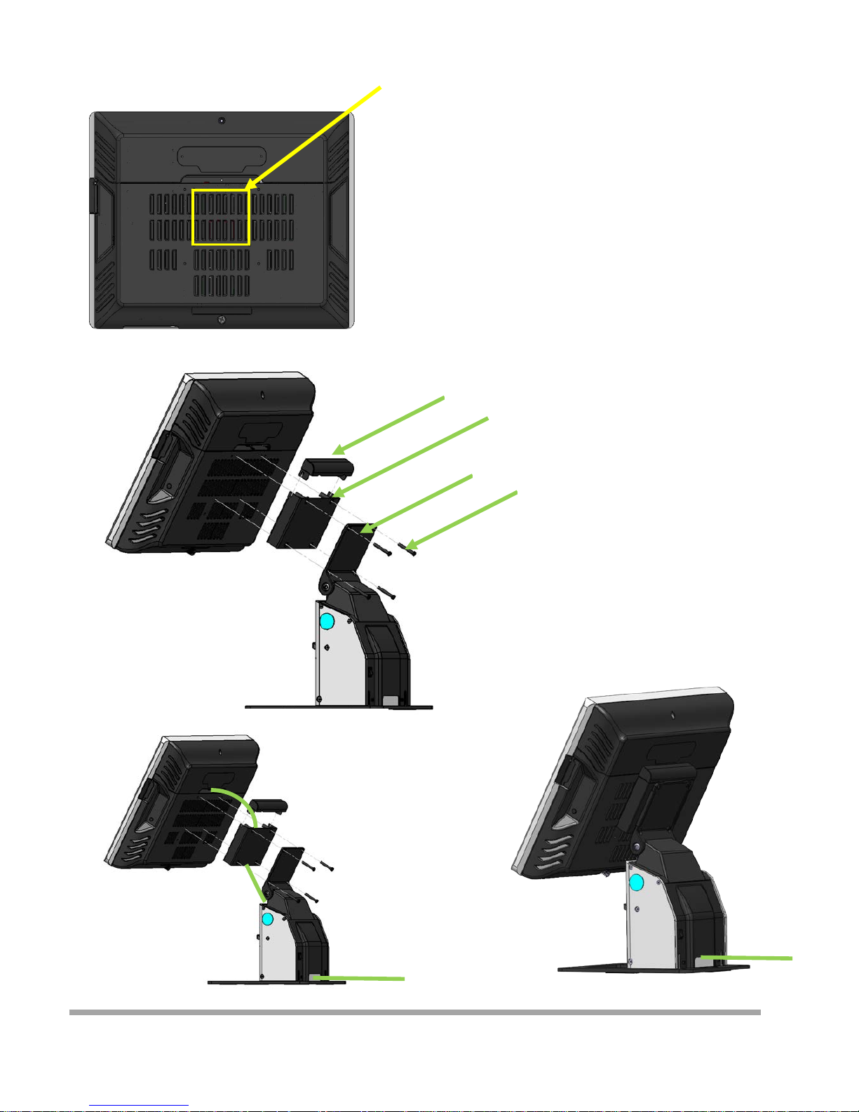
Installing A8V Printer
Lock the cable box and A8 on the
screw holes of the VESA75
Cover
Cable box
A8V
4 Screws
1. Put the Cable box on the back of CZAR
2. Put the A8V on the Cable box
3. Determine screw holes are aligned
4. Lock four screws
5. Install the Cover
How to install cable
15

Introduction
The purpo se o f this manual i s to descr ibe the set tings in the AMI UEFI BIOS Setup program on t his
motherboard. The Setup program allows users to modify the basic system configuration and save
these settings to NVRAM.
UEFI BIOS determines what a computer can do without accessing programs from a disk. This
system controls m ost of the input and ou tput d evices su ch as keyboar d, mous e , serial ports and disk
drives. BI O S activates a t the first stage of th e booting process, l oadin g and executing the op erating
system. Some addi tio nal feat ur es, such as virus and password protect ion or chipset fine-tuning
optio ns are also incl uded i n UEFI BIOS.
The rest of this ma nual will to g uide you t hro ugh t he optio ns and set ti ngs in UEFI BIOS Setup.
Plug and Play Support
This AMI UEFI BIOS supports the Plug and Play Version 1.0A specification.
EPA Green PC Support
This AMI UEFI BIOS sup ports Version 1.03 of the EPA Gree n PC spe cification.
ACPI Support
AMI ACPI UEFI BIOS support Version 1.0/2.0 of Advanced Configuration and Power interface specification
(ACPI). It provides ASL code for power management and device configuratio n capabilities as defined in the ACPI
specification, developed by Microsoft, Intel and Toshiba.
PCI Bus Support
This AMI UEFI BIOS also supports Version 2.3 of the Intel PCI (Peripheral Component Interconnect)
local bus specification.
DRAM Support
DDR3 SDRAM (Doub le Data Rate III Synchro nous DRAM) is supported.
Supported CPUs
This AMI UEFI BIOS supports the la test CPU.
Using Setup
When starting up the computer, press <Del> during the
Power-On Self-Test (POST) to enter the UEFI BIOS setup
utility.
In the UEFI BIOS setup utility, you will see General Help
description at the top right corner, and this is providing
a brief description of the selected item. Navigation
Key s f or that partic ular m enu are a t the bottom ri ght
corner, and you can use these keys to select item and
change the setti ngs.
5
16

▶
Note
» The default UEFI BIOS settings apply for most conditions to ensure optimum performance of the
motherboa rd. I f the sys tem becom es unstable after changing any settings, please load the defa ult
settings to ensure system’s compatibility and stability. Use Load Setup Default under the Exit Menu.
» For better system per forma nce, the UEFI BIOS firmware is bei ng co nt i nuous l y updated . The
UEFI BIOS information described i n thi s ma nual i s for your refe rence only. The actual UEFI BIOS
information and settings on board may be slightly different from this manual.
» The content of this manual is subject to be changed without notice. We will not be responsible for
any mistakes found in this user’s manual and any system damage that ma y be ca used by
wrong-settings.
17
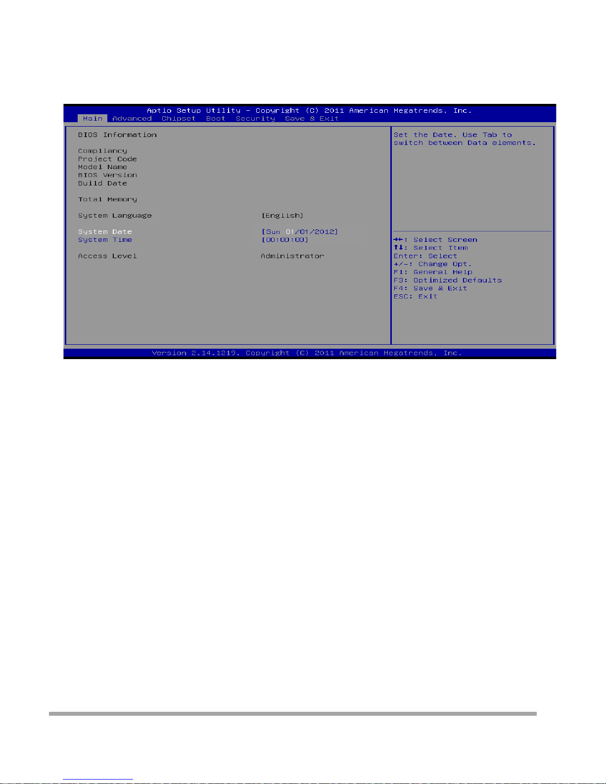
Main Menu
Once you enter AMI UEFI BIOS Setup Utility, the Main Menu will appear on the screen providing an
over view of the basic system inform ation.
BIOS Information
Shows system information including UEFI BIOS version, model name, marketing name, built date, etc.
Memory Frequency
Show s the system memory frequency.
Total Memory
Shows system memory size, VGA shard memory will be excluded.
System Date
Set the system date. Note that the ‘Day’ automatically changes when you set the date.
System Time
Set the system internal clock.
Access Level
Shows the access level of current user.
18
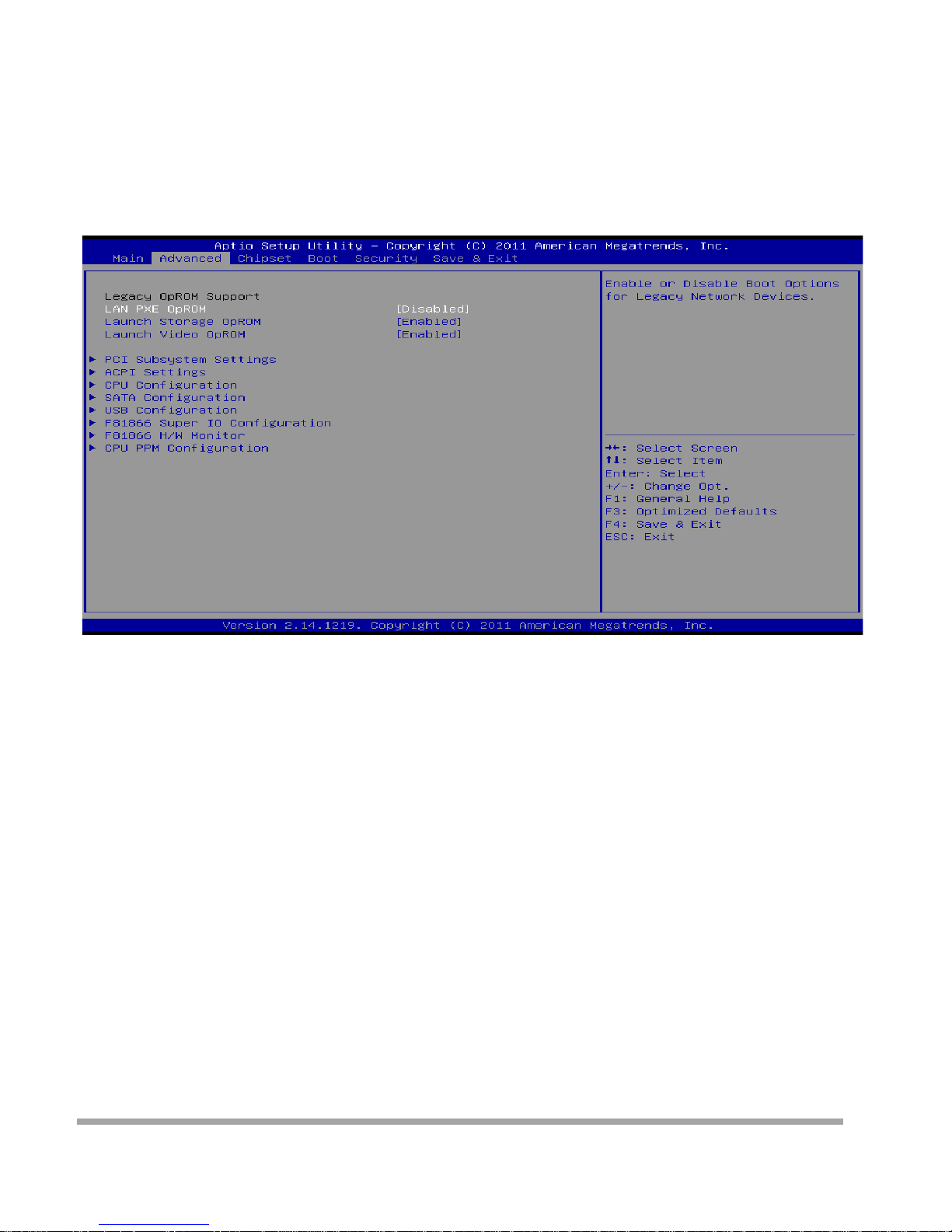
Advanced Menu
The Advanced Menu allow s you to configure the setting s of CPU, Super I/O, Power Ma nagem ent,
and ot her system d evices .
▶
Note
» Beware of that setting i nappro pr ia te val ues in items of this menu may cause system to malfunction.
» The options and default settings might be different by RAM or CPU models.
Launch PXE OpROM
This item enables or disables boot Options fo r legacy networ k dev ice s wi t h optio n ROM. Opt io ns:
Disabled ( Default ) / Enabled
Launch Stora ge Op ROM
This item enables or disables boot Options for legacy mass storage devices with option ROM.
Options: Enabled (Default) / Disabled
Launch Video OpROM
Th is item en ables or disa bles ex ecution of the legacy option RO M for video devi ces.
Options: Enabled (Default) / Disabled / Enabled when no UEFI Driver
19
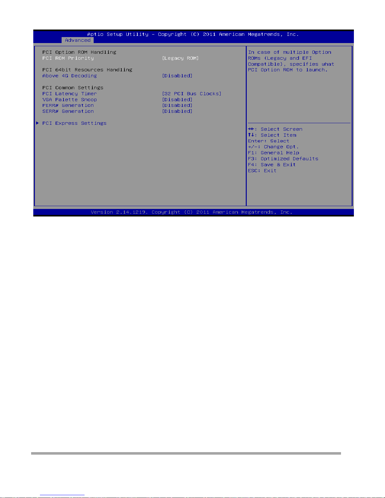
PCI Subsystem Settings
PCI ROM Priority
In case of multiple option ROMs (Lega cy and EFI Compatible) , this item spe cifies what PCI Option ROM
to launch
Options: Legacy ROM (Default) / EFI Compatible ROM
Above 4G Decoding
Enables or disables 64bit capable device to be decod ed i n above 4G address space (only if system
suppo rt 64 bit PCI decoding).
Options: Di sabled ( De fa ult ) / Enabled
PCI Latency Timer
This item sets the value to be progr am m ed into PCI Latency Timer Regi ste r .
Options: 32 PCI Bus Clocks (Default) / 64 PCI Bus Clocks / 96 PCI Bus Cl ocks / 128 PCI Bus Clocks /
160 PCI Bus Clocks / 192 PCI Bus Clocks / 224 PCI Bus Clocks / 248 PCI Bus Clocks
VGA Palett e Sn oop
En ables or disables VGA palette registers s noopi ng.
Options: Di sabled ( De fa ult ) / Enabled
PERR# Generation
Enables or disables PCI device to generate SERR#.
Options: Di sabled ( De fa ult ) / Enabled
SERR# Generation
Enables or disables PCI device to generate SERR#.
Options: Di sabled ( De fa ult ) / Enabled
20
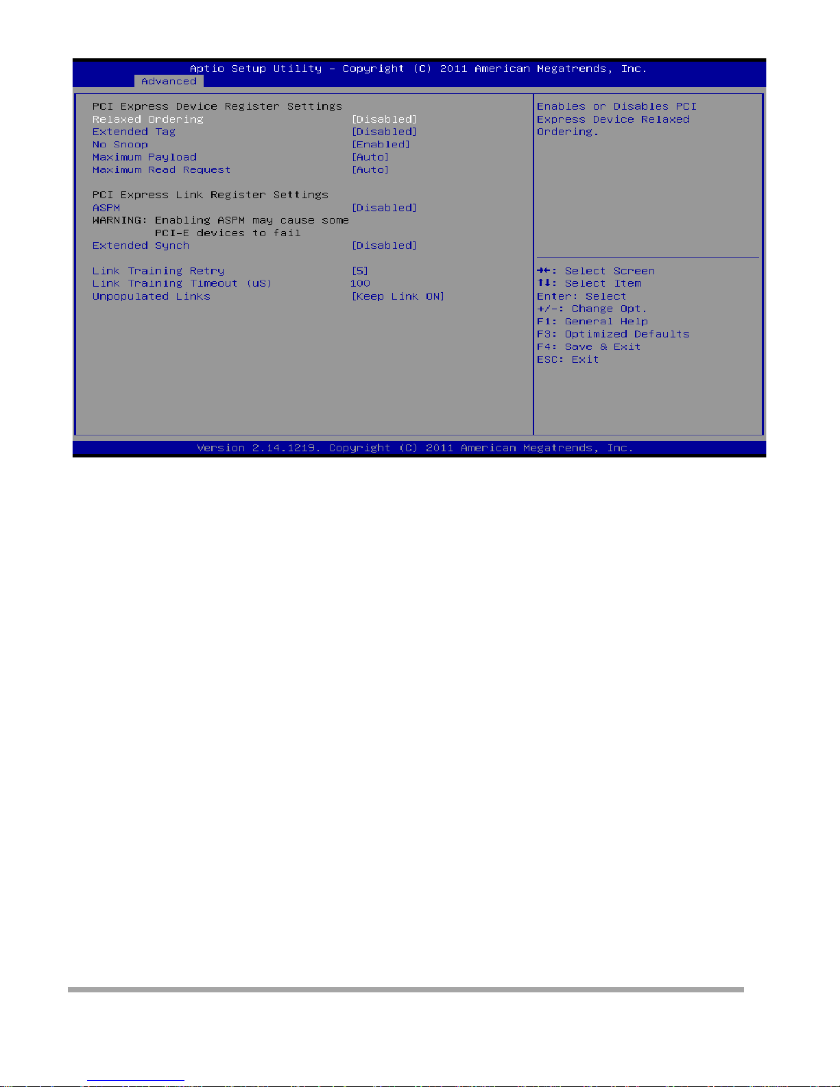
PCI Express Settings
Relaxed Ordering
Enables or disables PCI express device No snoop option.
Options: Di sabled ( De fa ult ) / Enabled
Extended Tag
If enabled allows device to use 8-bit tab field as a requester.
Options: Disabled (Default) / Enabled
No Snoop
This item enables or disables PCI Express Device No Snoop option.
Options: Enabled ( Defa ult) / Disabled
Maximum Payload
This item sets Maxim um Payload of PCI Exp re ss De vice or allows System BIOS to select the val ue.
Options: Auto (Default) / 128 Bytes / 256 Bytes / 512 Bytes / 1024 Bytes / 2048 Bytes / 4096 Bytes
Maximum Read Request
This item sets Maximum Read Req uest Size of PCI Express De vi ce or allow s System BIOS to select the
value.
Options: Auto (Default) / 128 Bytes / 256 Bytes / 512 Bytes / 1024 Bytes / 2048 Bytes / 4096 Bytes
ASPM
This item sets the ASPM (Active State Power Management Settings) Level: Force L0 – Force all links to
LO State; Auto – BIOS auto configures; Disabled – Disables ASPM.
Options: Disabled (Default) / Auto / Force L0s
Extend Synch
If enabled allows generation of extended synchronization patterns.
Options: Di sabled ( De fa ult ) / Enabled
Link Training Retry
21

Defines number of retry attempts software w ill take to retrain the link if previous training a t tempt w as
unsuccessful.
Options: 5 (De fa ult) / Disabled / 2 / 3
Link Training Timeout (uS)
Defines number of microseconds software will wait before polling ‘Link Training’ bit in link status register.
Value range is from 10 to 1000 uS.
Options: 100 (Default)
Unpopulated Links
In order to sa ve power, software will disable unpop ulated PCI Express links, if this option set to ‘Disabl e
Link’.
Options: Keep Li nk ON (Default) / Disable Link
22

ACPI Settings
Enable ACP I Auto Configuration
This item enab les or disables BIOS ACPI auto co nfigura tio n.
Options: Di sabled ( De fa ult ) / Enabled
Enable Hibernati on
This item enab les or disables system ability to hibe r nate (OS/ S4 sleep stat e) / This option may be not
effective with some OS.
Options: Enabled ( Defa ult) / Disabled
ACPI Sleep St at e
This item sele ct s the hig hest ACPI sleep s tate t he sy stem wi ll enter when the SUSPEND button is
pressed.
Options: S1 (CPU Stop Clock) (Default) / Suspend Disabled / S3 (Suspend to RAM)
Lock Legacy Resources
This item enables or disables lock of legacy resources.
Options: Di sabled ( De fa ult ) / Enabled
S3 Video Repost
This item enab les or disables S3 Video Repost..
Options: Di sabled ( De fa ult ) / Enabled
PME Wake u p from S5
This item enab les the system to wake from S5 using PEM event.
Options: Di sabled ( De fa ult ) / Enabled
23

Wake system wi th Fi xed Ti me
This item enables or disables the system to wake on by alarm event. When this item is enabled, the
system will wake on the hr::min::sec specified.
Options: Di sabled ( De fa ult ) / Enabled
Wake u p date
You can choo se w hich date the system will boot up.
Wake u p hou r / Wake up minu t e / Wake up second
You can choose the system boot up time, input hour, minute and second to specify.
USB Device Wakeu p from S3/S4
This item allow s you to enabl e or disable d t he USB resume from S3/S4 function.
Options: Di sabled ( De fa ult ) / Enabled
Restore AC Power Loss
This item enab les the system to wake from S5 using Ring-In even t.
Options: Power Off (Default) / Power On / Last State
Ring-In Wake up from S5
This item enab les the system to wake from S5 using Ring-In even t.
Options: Di sabled ( De fa ult ) / Enabled
PS2 Keyboa r d PowerOn
This item allow s you to control the keyboard power on function.
Options: Disabled (Default) / Ctrl + Esc / Ctrl + F1 / Ctrl + Space / Any Key / Wake Ke y / Power Key / Ctrl
+ Alt + Space / Space
PS2 Mouse PowerOn
This item allow s you to control the mouse power on function.
Options: Di sabled ( De fa ult ) / Enabled
24
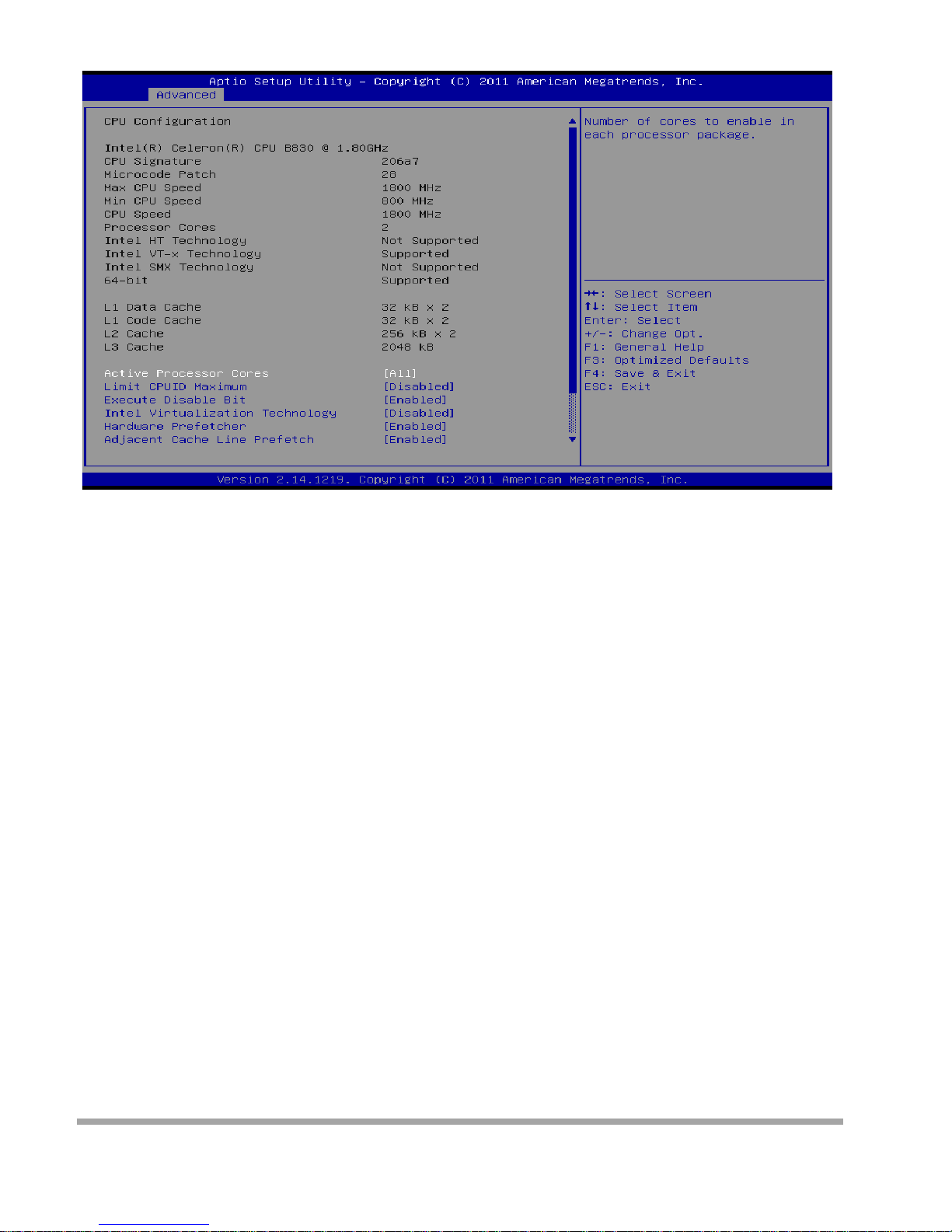
CPU Configu ra tion
Active Processor Cores
This item sets numbe r o f cores to enable in each processor package.
Options: All (Defa ult) / 1 / 2 / 3
Limit CPUID Maximum
When the comp ute r i s booted up, t he opera ti ng sys tem executes the CPUID instruct io n to identify the
processor and its capabilities. Before it can do so, it must first query the processor to find out the highest
input value CPUID recognizes. This determines the kind of basic information CPUID can provide the
operating system.
Options: Di sabled ( De fa ult ) / Enabled
Execute-Disable Bit
XD can pr event certain classes of malicious buffer overflow att acks wh en c ombined with a suppor ting
OS (Window s Ser ver 2003 SP1, Windows XP SP2, SuSE Linux 9. 2, Red Hat Ente rpri se 3 Update 3. ).
Options: Enabled (Default) / Disabled
Int el Vi rtualization Technol ogy
Virtual ization Technology can virtual ly separate your system resource into several part s, thus enhance
the per formanc e w hen r unning virtual machines or multi i nterfa ce systems. Options: Disabled ( De fault) /
Enabled
25

Hardware Prefetcher
Th e processor has a h ardware prefetch er t hat automat ically analyzes its requ iremen t s and prefetches
data and instructions from the memory into the Level 2 cache that are likely to be required in the near
future. Thi s reduce s the latency associated with memory read s . Options: Enabled ( Default) / Disabled
Adjacent Cache Line Prefetch
Th e processor has a h ardware adjacent cache l ine prefetch m echanism th at automatic ally f etches an
extra 64-byte cache line whenever the processor requests fo r a 64-byte cache line. This reduces cache
latency b y maki ng the next cache li ne imm edia tel y available if the processor requires it as well.
Options: Enabled ( Defa ult) / Disabled
TCC Activat i on off set
Offset from the factory TCC activation temperature
Options: 0 (Default)
CPU Max Current li mit value (Amp)
The Maximum instantaneous curre nt allow for Pr imar y Pla ne.
IGFX Max Current l i mit valu e (Amp)
The Maximum instantaneous curre nt allow for Secondary Plane.
26

SATA Configuration
SATA Controller(s)
This item enab les/disables Serial ATA Device. Options: Enabled (Default) / Disabled
SATA Mode Selection
This item determines how SATA controller(s) operate. Options: IDE (Default) / AHCI
Note: mSATA function is optional.
27
 Loading...