

Page 1

®Copyright 2015 July All Rights Reserved Version 1.0
The information contained in this document is subject to change without notice. We make no warranty of any
kind with regard to this material, including, but not limited to, the implied warranties of merchantability
and fitness for a particular purpose. We shall not be liable for errors contained herein or for incidental
or consequential damages in connection with the furnishing, performance, or use of this material.
This document contains proprietary information that is protected by copy right. All rights are reserved. No part of
this document may be photocopied, reproduced or translated to another language without the prior
written consent of the manufacturer.
TRADEMARK
Intel®, Pentium® and MMX are registered trademarks of Intel® Corporation. Microsoft® and Windows® are
registered trademarks of Microsoft Corporation.
Always high- speed! absolutely desirable
Page 2

Main Board
CPU
PP-8500-15 Support IVY & Sandy Bridge Intel® Core i5 Dual Cores CPU
PP-8300-15
Support IVY & Sandy Bridge Intel® Core i3 Dual Cores CPU
Chipset
Intel® HM76 Express Chipset
System Memory
2x SO-DIMM (204pin) Slot, DDR3 1333 MHz, Max 8GB
Graphic Memory
Intel® HD 4000 Series Graphics
LCD Panel
PP-8500 -15 / PP8300 -15
Panel Size 15”
Maximum Resolution 1024 x 768
Brightness 250 cd/m1
Contrast Ratio 700 : 1
Response Time 16 ms
View Angles (H/V) 150 / 120
Touch Panel Five Wires Resistive Touch or Projected Capacitive Touch
Storage
HDD 2.5” SATAIII /SATAIII interface x 2
Expansion
Socket One Mini-PCIE or One Msata II
Power
Power Adaptor Input AC 100-240V 2.5A 50/60Hz, Output DC 12V 6.66A
I / O
USB Four USB 2.0, Two USB 3.0
Serial Four COM ports with DB-9 Connector
COM1, COM2 with 0V / 5V / 12V power selectable
COM3, COM4 with 0V / 5V / 12V power selectable
LAN One Realtek 8111F Gigabit Fast Ethernet controllers
2nd VGA Output One 15 Pin VGA Port
PS/2 One
Audio One Earphone & One Microphone
1
1
Page 3

Cash Drawer One RJ-11
Control/Indicator
Power Button One
LED Indicators Power (Red)
Optional Peripherals
Magnetic Card Reader ISO Track 1/2/3, USB interface
VFD customer display 20 x 2 characters, RS-232 interface
Dimensions
PP-8300-15 PP-8500-15
358(W) X 70(L) X 293(H) mm
PP-8300-T15 PP-8500-T15 358(W) X 223.9(L) X 309.6(H) mm
Environment
Operating Temperature 0°C ~ 40°C ( 32°F ~ 104°F )
Storage Temperature - 20°C ~ 60°C ( - 4°F ~ 140°F )
Operating Humidity 10% - 80% RH non condensing
Storage Humidity 10% - 80% RH non condensing
Model Number
PP-8500-X – SS IVY & Sandy Bridge Intel® Core i5 Dual Cores CPU
X : T --- Contain foot
SS : 15 --- 15" TFT LCD
PP-8300-X – SS IVY & Sandy Bridge Intel® Core i3 Dual Cores CPU
X : T --- Contain foot
SS : 15 --- 15" TFT LCD
2
Page 4
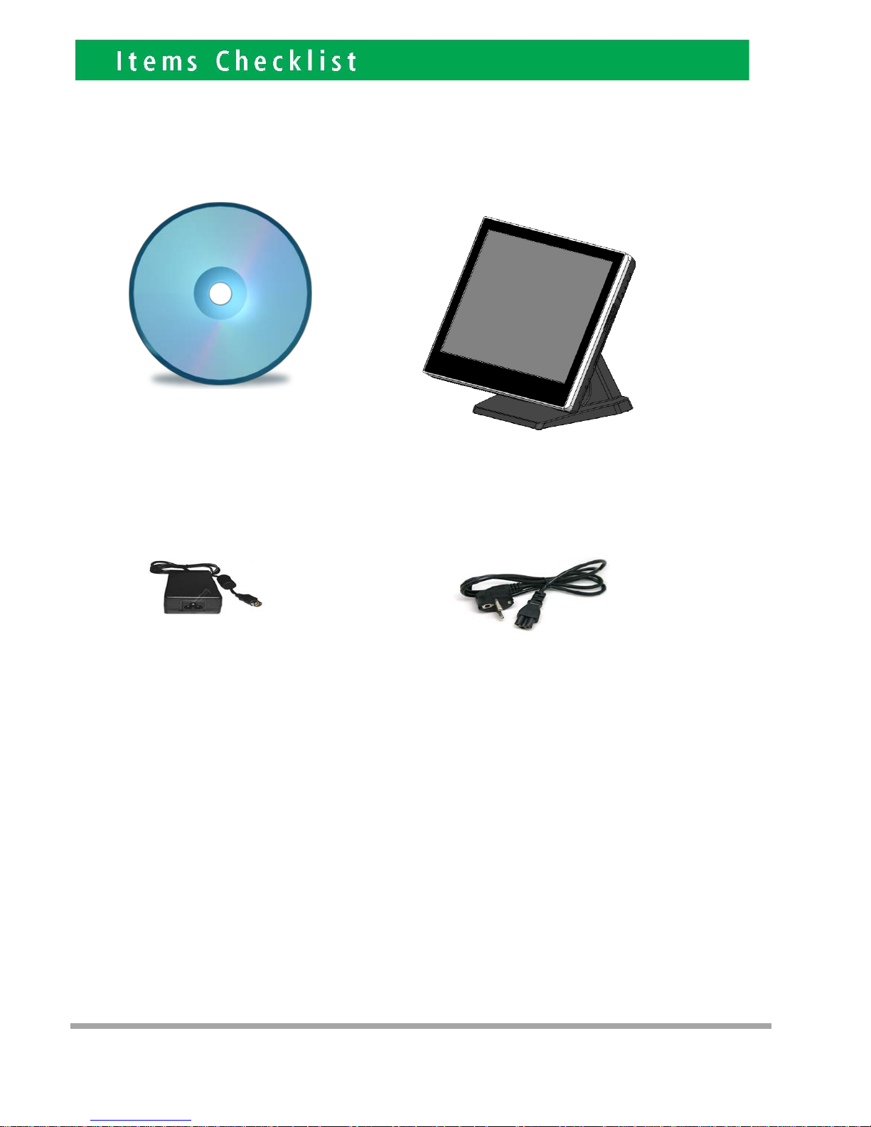
If any item is missin g, pl ease con t act your sale agent i mmediat el y.
Tak e the system unit out from the carton. Remove the unit by carefully holding the foam inserts and remove slowly to protect
the system. The following items should be found in the carton:
1. CD that including all
driver and manual
2. The System
. Power Adaptor 4. AC Power Cord
2
3
Page 5
Please un plug th e A C power of the adapter before opening an y part of the system. Sin ce t he
standby power is always on after the adapter is plugged in. It may cause permanen t damage to
your system when you open any part of i t .
3
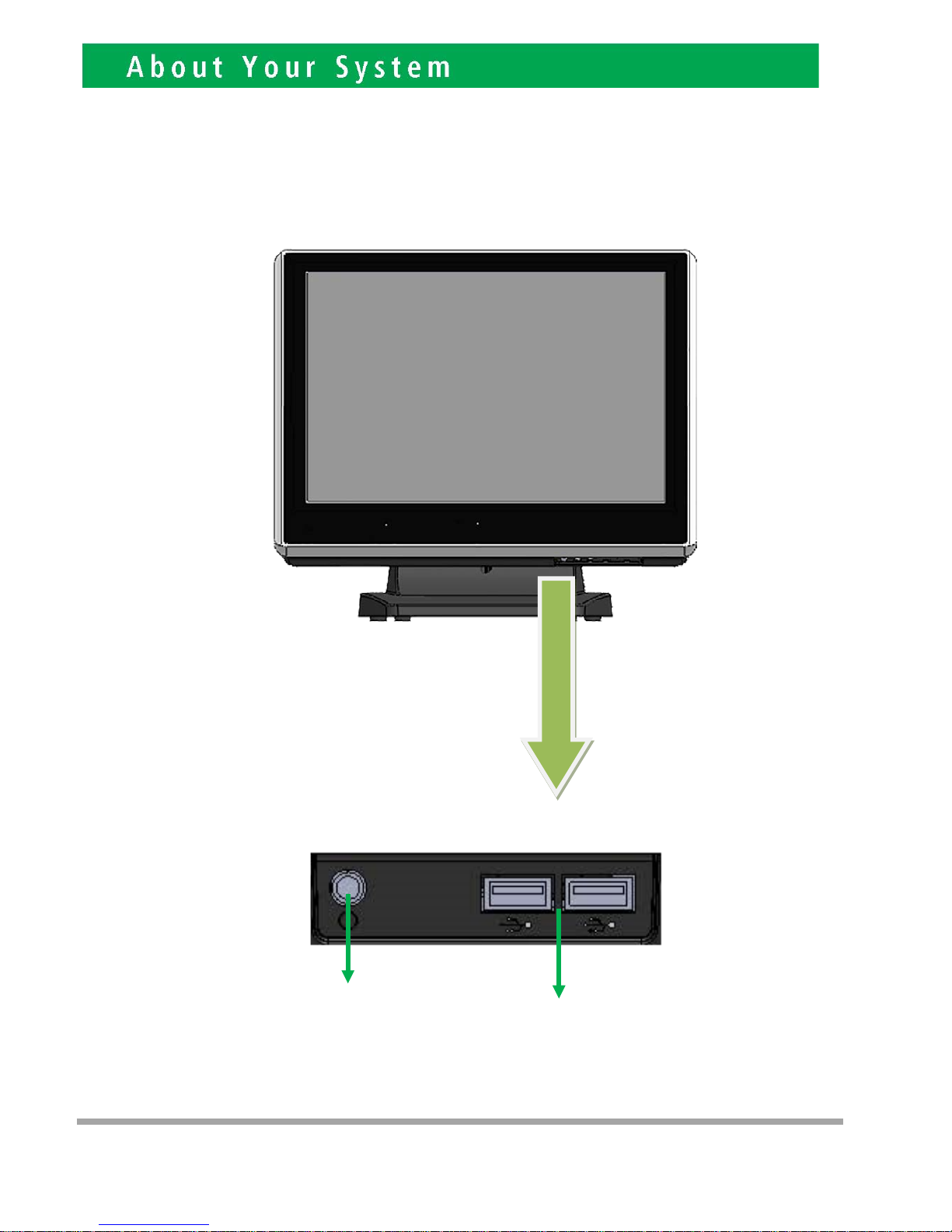
Front View
Power
Button
USB 2.0
4
Page 6
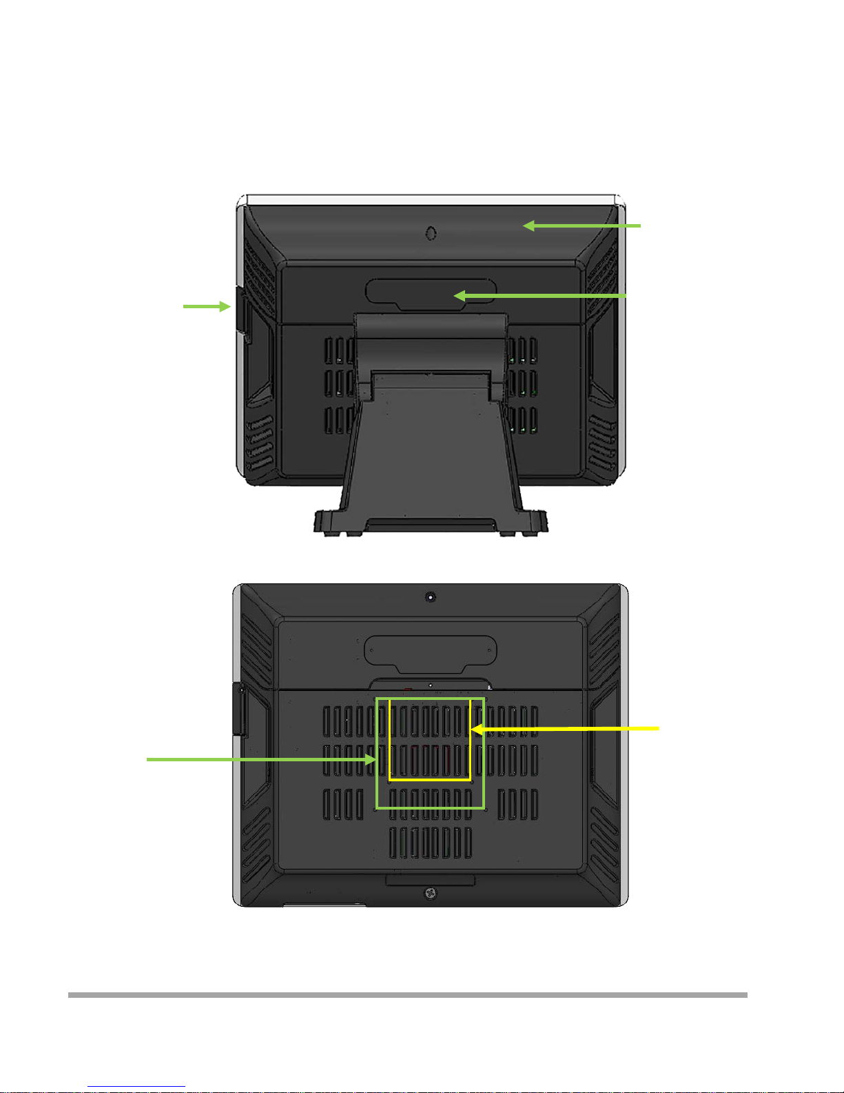
Rear View
Slot for installing
Magnetic Card
Rea der (op t ional)
Cable Cover
Slot for installing
Custo m Display
or Second Display
(optional)
VESA 75
VESA 100
5
Page 7
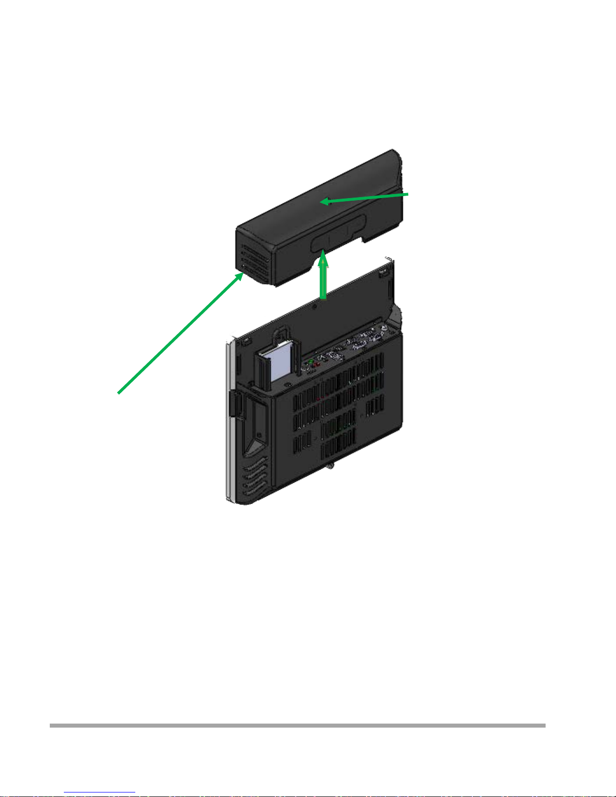
How to open the connector bezel
Please un plug th e A C power of the adapter before opening an y part of the system.
Since the standby power is always on after the adapter is pl ugged in.
It may cause permanent damage to your system w hen you open any part of it.
As illustrated in
the follow i ng,
Move these two sides upward
Release the screw
6
Page 8
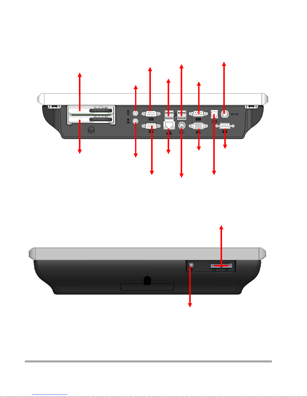
The connector panel
1. TOP of machine
2. Bottom of machine
Hard Disk 2
Power IN
Earphone
Microphone
USB 3.0
USB 2.0
VGA
LAN
COM3
COM4
P S /2
Power Button
USB 2.0
COM1
COM2
RJ11
Hard Disk 1
7
Page 9
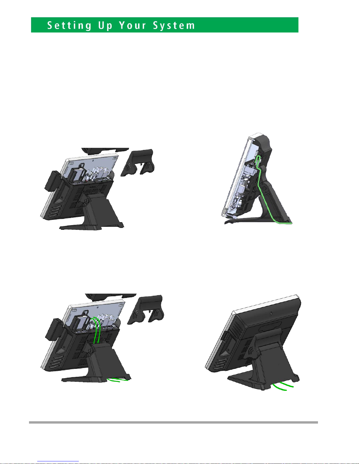
Please un plug th e A C power of the adapter before opening an y part of the system. Sin ce t he
standby power is always on after the adapter is plugged in. It may cause permanen t damage to
your system wh en you open any part of the system.
Installing Peripherals
To install the peripheral’s cables, please follow the method described below.
It will make the process much easier.
1. Open the Cable cover and Hinge cover 2. Follow the way of drawing to wiring
Plug in all the cable on the hots
3. Through the cable between HOST and FOOT
4
8
Page 10
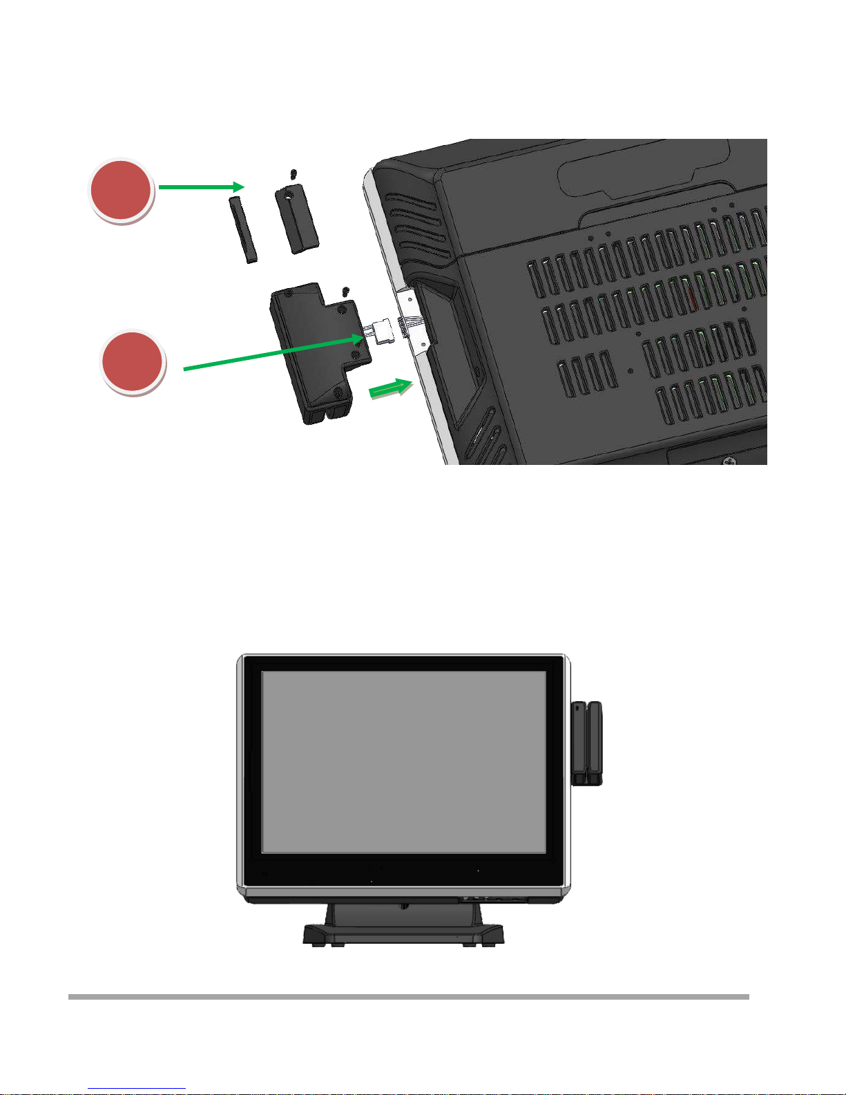
Installing Magnetic Card Reader (MSR)
1. Remove the rubber mat,Loosen the screw,and remove the MSR cover
2. Connected to the cable on the MSR and host,and lock two screws
1
2
9
Page 11
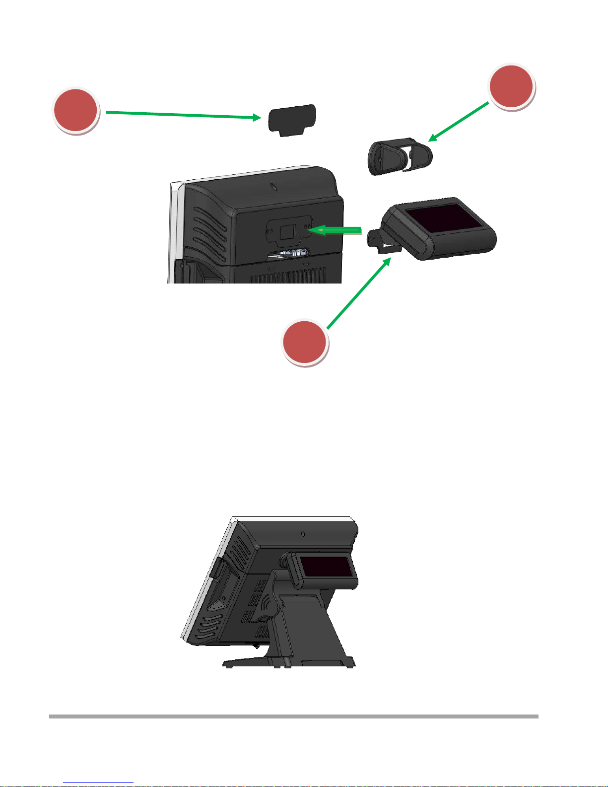
Installing Customer Display
1
2
3
1. Remove the metal bezel
2. Connected to the cable, lock the two screws on Cable Cover
3. Installation VFD cover and lock the two screws
10
Page 12

Installing Second Display
1. Remove the metal bezel
2. Connected to the cable, lock the two screws on Cable Cover
3. Installation VFD cover and lock the two screws
1
2
3
11
Page 13
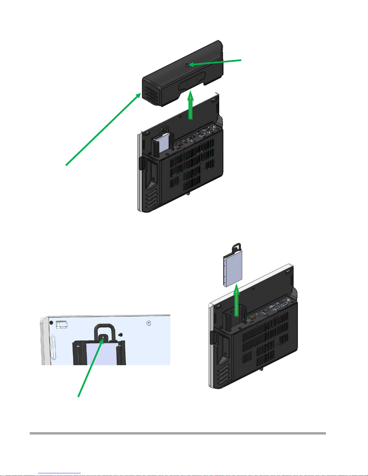
Replace and Installing Hard Disk
1. Release the screw
4. Grab the h andle and pull up or down
Remove or Installation Hard disk
2. Move these two side s upward
3. Release the screw
12
Page 14
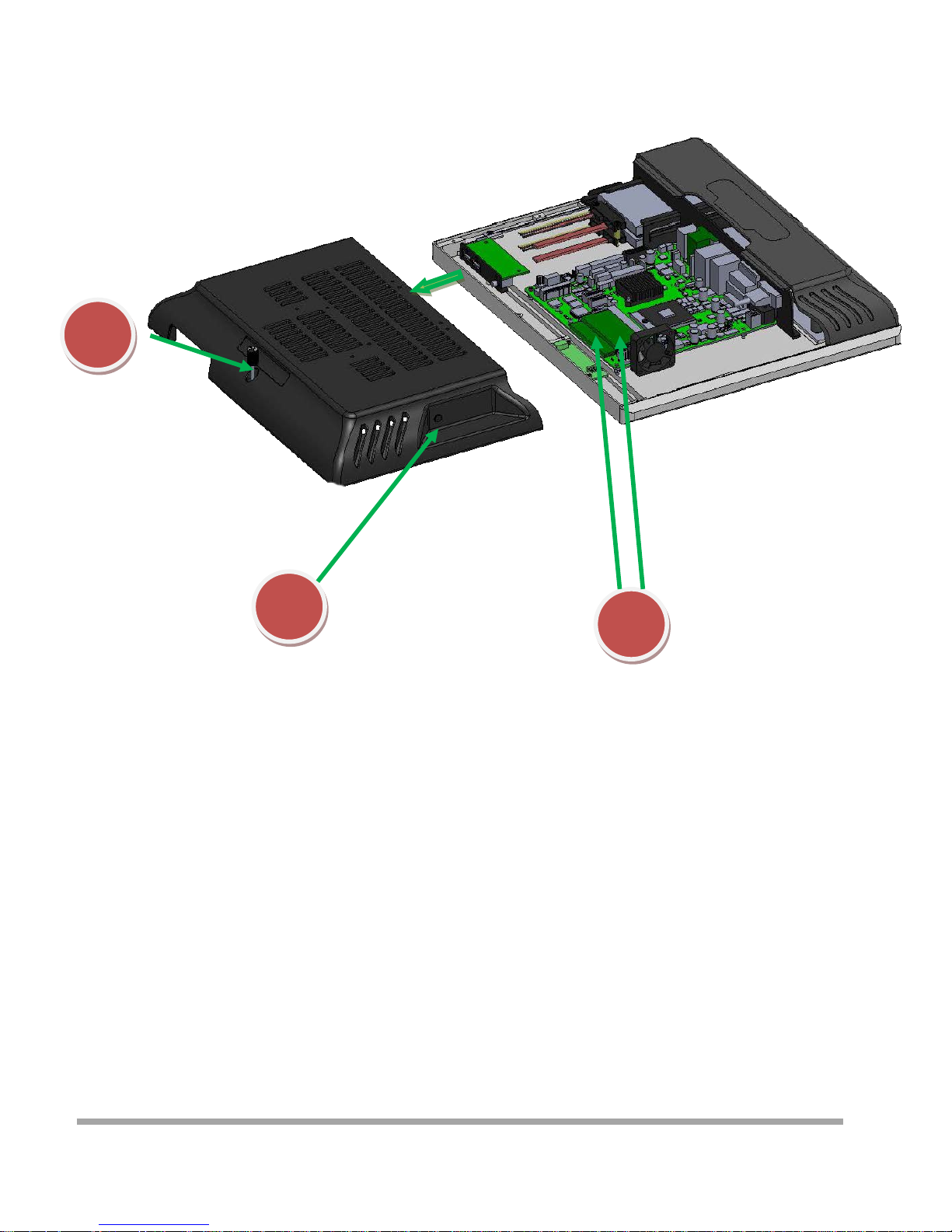
Replace and Installing Memory
1
2
1. Release the screw
2. Grasp the both sides , and pulled down the back cover
3. Replace or Installing Memory
3
13
Page 15
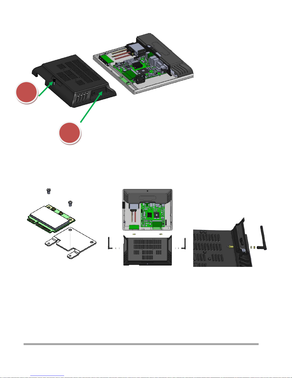
Installing WIFI Card and Antenna
1
2
1. Release the screw
2. Grasp the both sides , and pulled down the back cover
3. Install WIFI Card
Lock 2 screws
4. Remove the plastic pad on the both sides
of the Main cover
5. Inst all Antenna
14
Page 16
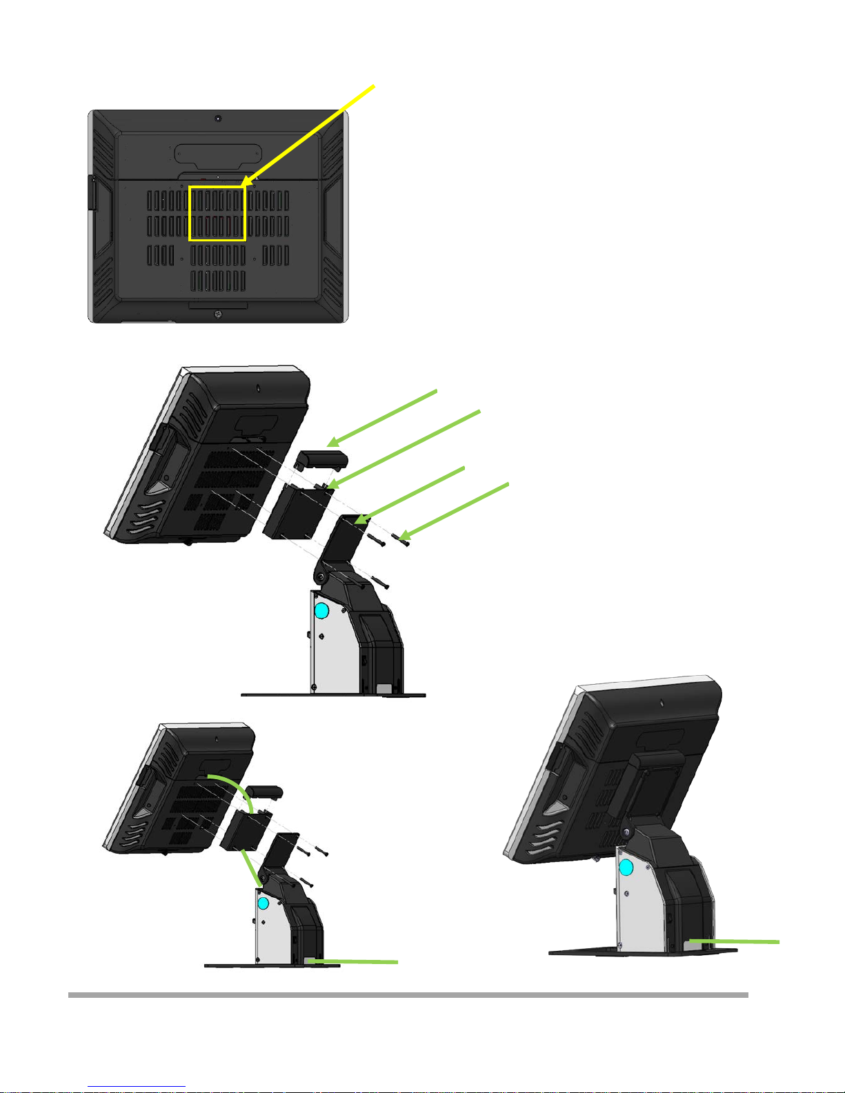
Installing A8V Printer
Lock the cable box and A8 on the
screw holes of the VESA75
Cover
Cable box
A8V
4 Screws
1. Put the Cable box on the back of CZAR
2. Put the A8V on the Cable box
3. Determine screw holes are aligned
4. Lock four screws
5. Install the Cover
How to install cable
15
Page 17

Introduction
The purpo se o f this manual i s to descr ibe the set tings in the AMI UEFI BIOS Setup program on t his
motherboard. The Setup program allows users to modify the basic system configuration and save
these settings to NVRAM.
UEFI BIOS determines what a computer can do without accessing programs from a disk. This
system controls m ost of the input and ou tput d evices su ch as keyboar d, mous e , serial ports and disk
drives. BI O S activates a t the first stage of th e booting process, l oadin g and executing the op erating
system. Some addi tio nal feat ur es, such as virus and password protect ion or chipset fine-tuning
optio ns are also incl uded i n UEFI BIOS.
The rest of this ma nual will to g uide you t hro ugh t he optio ns and set ti ngs in UEFI BIOS Setup.
Plug and Play Support
This AMI UEFI BIOS supports the Plug and Play Version 1.0A specification.
EPA Green PC Support
This AMI UEFI BIOS sup ports Version 1.03 of the EPA Gree n PC spe cification.
ACPI Support
AMI ACPI UEFI BIOS support Version 1.0/2.0 of Advanced Configuration and Power interface specification
(ACPI). It provides ASL code for power management and device configuratio n capabilities as defined in the ACPI
specification, developed by Microsoft, Intel and Toshiba.
PCI Bus Support
This AMI UEFI BIOS also supports Version 2.3 of the Intel PCI (Peripheral Component Interconnect)
local bus specification.
DRAM Support
DDR3 SDRAM (Doub le Data Rate III Synchro nous DRAM) is supported.
Supported CPUs
This AMI UEFI BIOS supports the la test CPU.
Using Setup
When starting up the computer, press <Del> during the
Power-On Self-Test (POST) to enter the UEFI BIOS setup
utility.
In the UEFI BIOS setup utility, you will see General Help
description at the top right corner, and this is providing
a brief description of the selected item. Navigation
Key s f or that partic ular m enu are a t the bottom ri ght
corner, and you can use these keys to select item and
change the setti ngs.
5
16
Page 18

▶
Note
» The default UEFI BIOS settings apply for most conditions to ensure optimum performance of the
motherboa rd. I f the sys tem becom es unstable after changing any settings, please load the defa ult
settings to ensure system’s compatibility and stability. Use Load Setup Default under the Exit Menu.
» For better system per forma nce, the UEFI BIOS firmware is bei ng co nt i nuous l y updated . The
UEFI BIOS information described i n thi s ma nual i s for your refe rence only. The actual UEFI BIOS
information and settings on board may be slightly different from this manual.
» The content of this manual is subject to be changed without notice. We will not be responsible for
any mistakes found in this user’s manual and any system damage that ma y be ca used by
wrong-settings.
17
Page 19
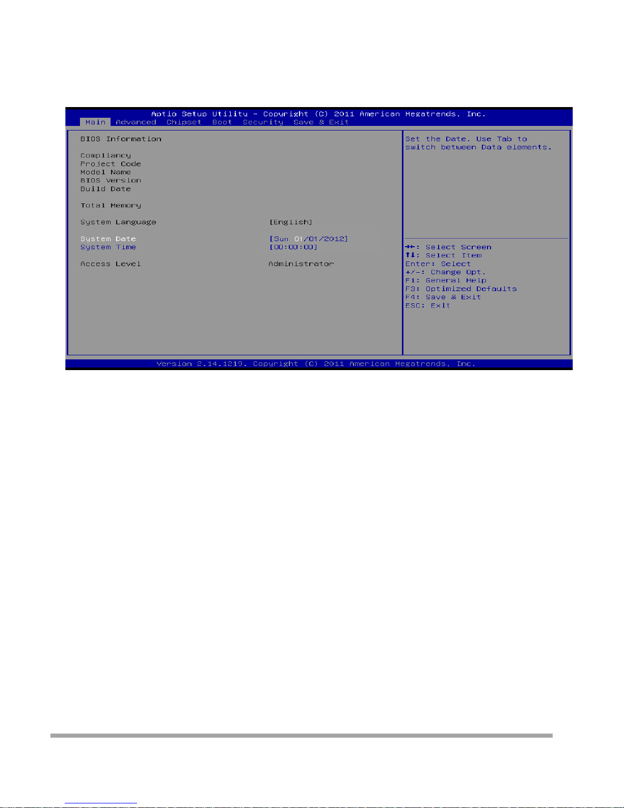
Main Menu
Once you enter AMI UEFI BIOS Setup Utility, the Main Menu will appear on the screen providing an
over view of the basic system inform ation.
BIOS Information
Shows system information including UEFI BIOS version, model name, marketing name, built date, etc.
Memory Frequency
Show s the system memory frequency.
Total Memory
Shows system memory size, VGA shard memory will be excluded.
System Date
Set the system date. Note that the ‘Day’ automatically changes when you set the date.
System Time
Set the system internal clock.
Access Level
Shows the access level of current user.
18
Page 20
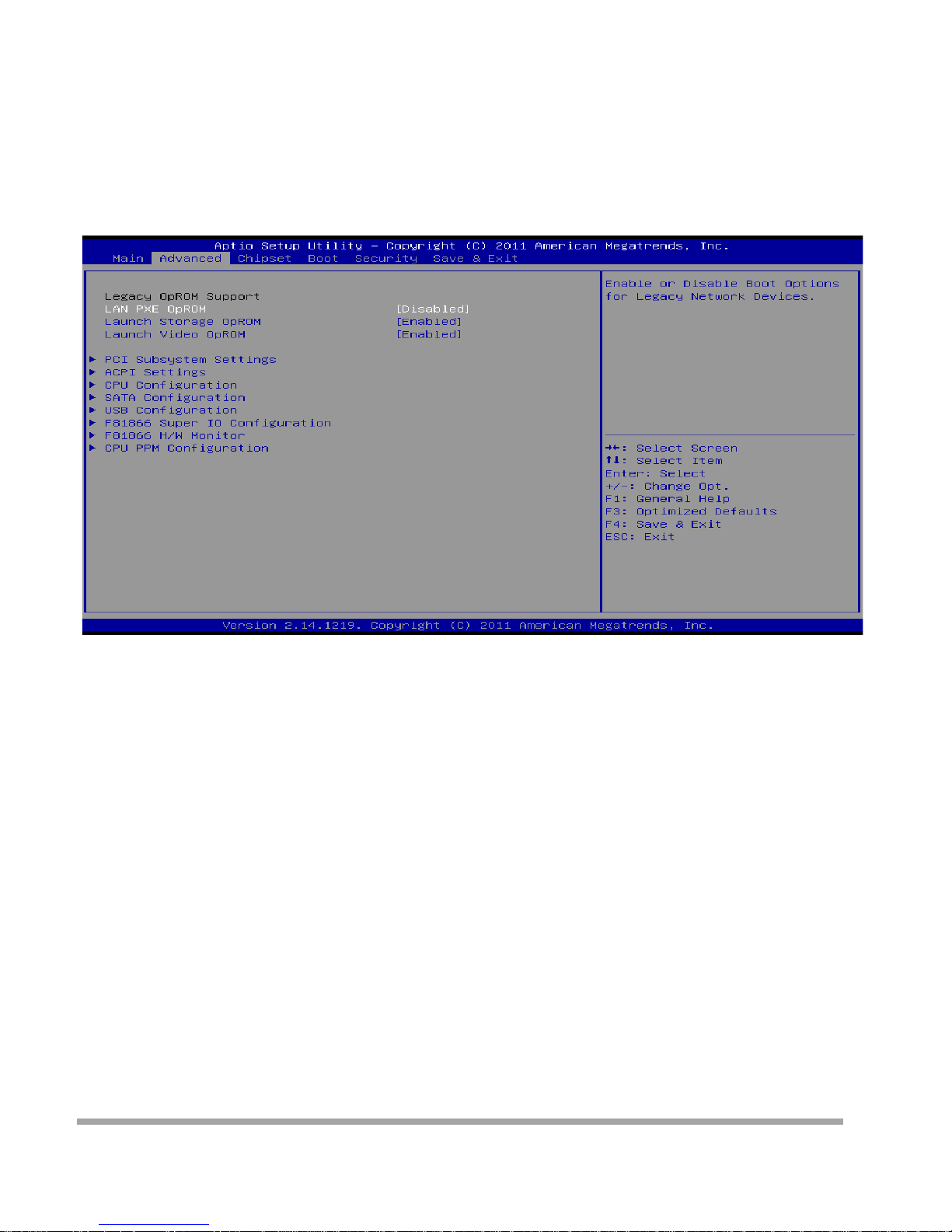
Advanced Menu
The Advanced Menu allow s you to configure the setting s of CPU, Super I/O, Power Ma nagem ent,
and ot her system d evices .
▶
Note
» Beware of that setting i nappro pr ia te val ues in items of this menu may cause system to malfunction.
» The options and default settings might be different by RAM or CPU models.
Launch PXE OpROM
This item enables or disables boot Options fo r legacy networ k dev ice s wi t h optio n ROM. Opt io ns:
Disabled ( Default ) / Enabled
Launch Stora ge Op ROM
This item enables or disables boot Options for legacy mass storage devices with option ROM.
Options: Enabled (Default) / Disabled
Launch Video OpROM
Th is item en ables or disa bles ex ecution of the legacy option RO M for video devi ces.
Options: Enabled (Default) / Disabled / Enabled when no UEFI Driver
19
Page 21
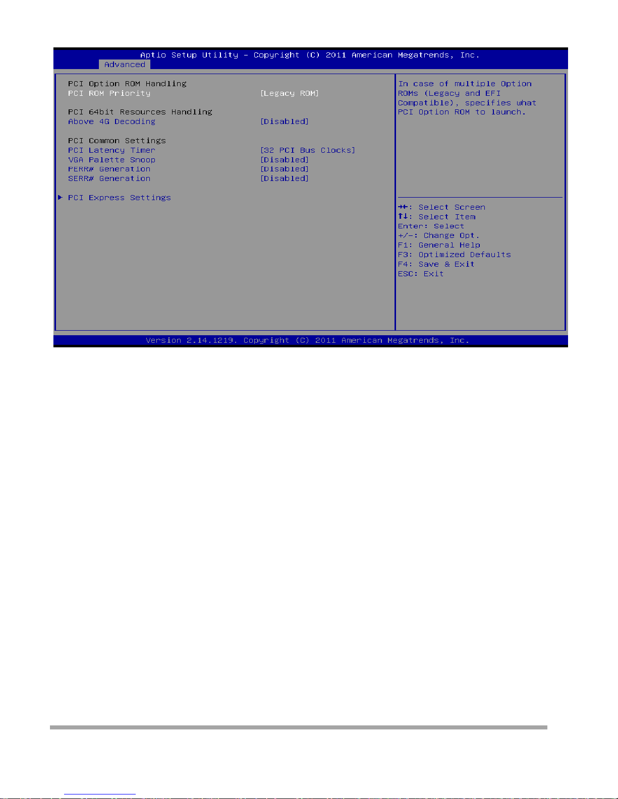
PCI Subsystem Settings
PCI ROM Priority
In case of multiple option ROMs (Lega cy and EFI Compatible) , this item spe cifies what PCI Option ROM
to launch
Options: Legacy ROM (Default) / EFI Compatible ROM
Above 4G Decoding
Enables or disables 64bit capable device to be decod ed i n above 4G address space (only if system
suppo rt 64 bit PCI decoding).
Options: Di sabled ( De fa ult ) / Enabled
PCI Latency Timer
This item sets the value to be progr am m ed into PCI Latency Timer Regi ste r .
Options: 32 PCI Bus Clocks (Default) / 64 PCI Bus Clocks / 96 PCI Bus Cl ocks / 128 PCI Bus Clocks /
160 PCI Bus Clocks / 192 PCI Bus Clocks / 224 PCI Bus Clocks / 248 PCI Bus Clocks
VGA Palett e Sn oop
En ables or disables VGA palette registers s noopi ng.
Options: Di sabled ( De fa ult ) / Enabled
PERR# Generation
Enables or disables PCI device to generate SERR#.
Options: Di sabled ( De fa ult ) / Enabled
SERR# Generation
Enables or disables PCI device to generate SERR#.
Options: Di sabled ( De fa ult ) / Enabled
20
Page 22
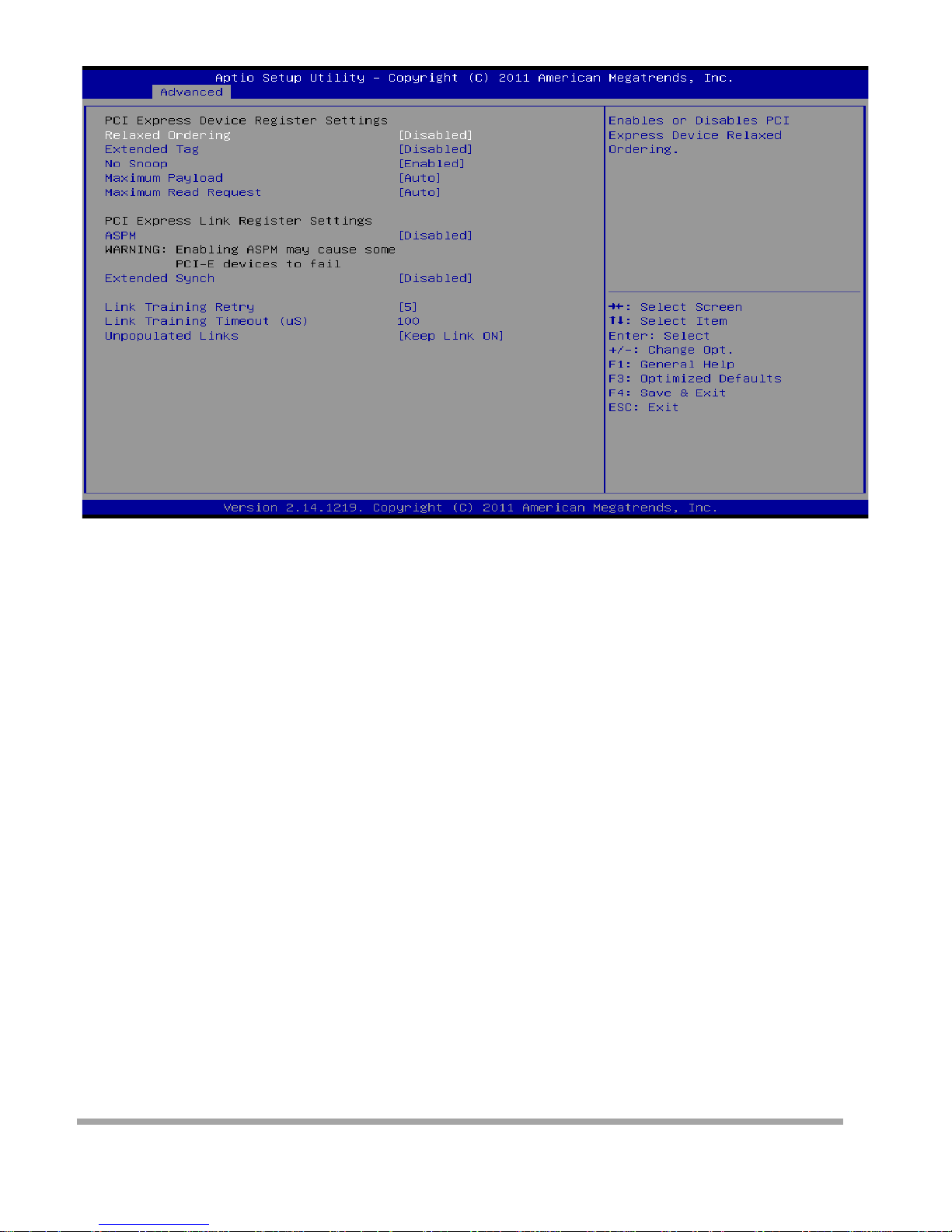
PCI Express Settings
Relaxed Ordering
Enables or disables PCI express device No snoop option.
Options: Di sabled ( De fa ult ) / Enabled
Extended Tag
If enabled allows device to use 8-bit tab field as a requester.
Options: Disabled (Default) / Enabled
No Snoop
This item enables or disables PCI Express Device No Snoop option.
Options: Enabled ( Defa ult) / Disabled
Maximum Payload
This item sets Maxim um Payload of PCI Exp re ss De vice or allows System BIOS to select the val ue.
Options: Auto (Default) / 128 Bytes / 256 Bytes / 512 Bytes / 1024 Bytes / 2048 Bytes / 4096 Bytes
Maximum Read Request
This item sets Maximum Read Req uest Size of PCI Express De vi ce or allow s System BIOS to select the
value.
Options: Auto (Default) / 128 Bytes / 256 Bytes / 512 Bytes / 1024 Bytes / 2048 Bytes / 4096 Bytes
ASPM
This item sets the ASPM (Active State Power Management Settings) Level: Force L0 – Force all links to
LO State; Auto – BIOS auto configures; Disabled – Disables ASPM.
Options: Disabled (Default) / Auto / Force L0s
Extend Synch
If enabled allows generation of extended synchronization patterns.
Options: Di sabled ( De fa ult ) / Enabled
Link Training Retry
21
Page 23

Defines number of retry attempts software w ill take to retrain the link if previous training a t tempt w as
unsuccessful.
Options: 5 (De fa ult) / Disabled / 2 / 3
Link Training Timeout (uS)
Defines number of microseconds software will wait before polling ‘Link Training’ bit in link status register.
Value range is from 10 to 1000 uS.
Options: 100 (Default)
Unpopulated Links
In order to sa ve power, software will disable unpop ulated PCI Express links, if this option set to ‘Disabl e
Link’.
Options: Keep Li nk ON (Default) / Disable Link
22
Page 24

ACPI Settings
Enable ACP I Auto Configuration
This item enab les or disables BIOS ACPI auto co nfigura tio n.
Options: Di sabled ( De fa ult ) / Enabled
Enable Hibernati on
This item enab les or disables system ability to hibe r nate (OS/ S4 sleep stat e) / This option may be not
effective with some OS.
Options: Enabled ( Defa ult) / Disabled
ACPI Sleep St at e
This item sele ct s the hig hest ACPI sleep s tate t he sy stem wi ll enter when the SUSPEND button is
pressed.
Options: S1 (CPU Stop Clock) (Default) / Suspend Disabled / S3 (Suspend to RAM)
Lock Legacy Resources
This item enables or disables lock of legacy resources.
Options: Di sabled ( De fa ult ) / Enabled
S3 Video Repost
This item enab les or disables S3 Video Repost..
Options: Di sabled ( De fa ult ) / Enabled
PME Wake u p from S5
This item enab les the system to wake from S5 using PEM event.
Options: Di sabled ( De fa ult ) / Enabled
23
Page 25

Wake system wi th Fi xed Ti me
This item enables or disables the system to wake on by alarm event. When this item is enabled, the
system will wake on the hr::min::sec specified.
Options: Di sabled ( De fa ult ) / Enabled
Wake u p date
You can choo se w hich date the system will boot up.
Wake u p hou r / Wake up minu t e / Wake up second
You can choose the system boot up time, input hour, minute and second to specify.
USB Device Wakeu p from S3/S4
This item allow s you to enabl e or disable d t he USB resume from S3/S4 function.
Options: Di sabled ( De fa ult ) / Enabled
Restore AC Power Loss
This item enab les the system to wake from S5 using Ring-In even t.
Options: Power Off (Default) / Power On / Last State
Ring-In Wake up from S5
This item enab les the system to wake from S5 using Ring-In even t.
Options: Di sabled ( De fa ult ) / Enabled
PS2 Keyboa r d PowerOn
This item allow s you to control the keyboard power on function.
Options: Disabled (Default) / Ctrl + Esc / Ctrl + F1 / Ctrl + Space / Any Key / Wake Ke y / Power Key / Ctrl
+ Alt + Space / Space
PS2 Mouse PowerOn
This item allow s you to control the mouse power on function.
Options: Di sabled ( De fa ult ) / Enabled
24
Page 26
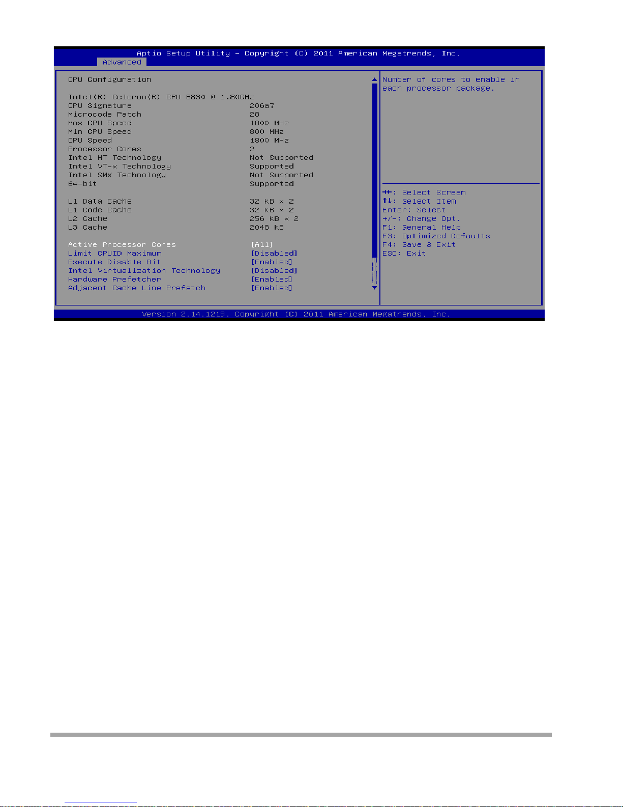
CPU Configu ra tion
Active Processor Cores
This item sets numbe r o f cores to enable in each processor package.
Options: All (Defa ult) / 1 / 2 / 3
Limit CPUID Maximum
When the comp ute r i s booted up, t he opera ti ng sys tem executes the CPUID instruct io n to identify the
processor and its capabilities. Before it can do so, it must first query the processor to find out the highest
input value CPUID recognizes. This determines the kind of basic information CPUID can provide the
operating system.
Options: Di sabled ( De fa ult ) / Enabled
Execute-Disable Bit
XD can pr event certain classes of malicious buffer overflow att acks wh en c ombined with a suppor ting
OS (Window s Ser ver 2003 SP1, Windows XP SP2, SuSE Linux 9. 2, Red Hat Ente rpri se 3 Update 3. ).
Options: Enabled (Default) / Disabled
Int el Vi rtualization Technol ogy
Virtual ization Technology can virtual ly separate your system resource into several part s, thus enhance
the per formanc e w hen r unning virtual machines or multi i nterfa ce systems. Options: Disabled ( De fault) /
Enabled
25
Page 27

Hardware Prefetcher
Th e processor has a h ardware prefetch er t hat automat ically analyzes its requ iremen t s and prefetches
data and instructions from the memory into the Level 2 cache that are likely to be required in the near
future. Thi s reduce s the latency associated with memory read s . Options: Enabled ( Default) / Disabled
Adjacent Cache Line Prefetch
Th e processor has a h ardware adjacent cache l ine prefetch m echanism th at automatic ally f etches an
extra 64-byte cache line whenever the processor requests fo r a 64-byte cache line. This reduces cache
latency b y maki ng the next cache li ne imm edia tel y available if the processor requires it as well.
Options: Enabled ( Defa ult) / Disabled
TCC Activat i on off set
Offset from the factory TCC activation temperature
Options: 0 (Default)
CPU Max Current li mit value (Amp)
The Maximum instantaneous curre nt allow for Pr imar y Pla ne.
IGFX Max Current l i mit valu e (Amp)
The Maximum instantaneous curre nt allow for Secondary Plane.
26
Page 28

SATA Configuration
SATA Controller(s)
This item enab les/disables Serial ATA Device. Options: Enabled (Default) / Disabled
SATA Mode Selection
This item determines how SATA controller(s) operate. Options: IDE (Default) / AHCI
Note: mSATA function is optional.
27
Page 29
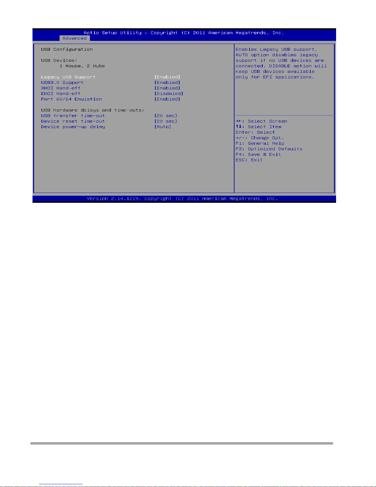
USB Configu ra tion
Legacy USB Suppo rt
This item determines if the BIOS should provide legacy support for USB devices like the keyboard,
mouse, and USB drive. This is a useful feature when using such USB devices with operating systems
that do not natively support USB (e.g. Microsoft DOS or Windows NT). Options: Enabled ( De faul t) /
Disabled / Auto
USB3.0 Support
This item enab les or disables USB3.0 (XHCI) co ntroll er suppor t.
Options: Enabled ( Defa ult) / Disabled
XHCI Hand-Off
This is a workaro und fo r OSes without XHCI ha nd-off support. The XHCI ownership change
should be claimed by XHCI driver.
Options: Enabled ( Defa ult) / Disabled
EHCI Hand-Off
This is a workaround for OSes without EHCI hand-off support. The EHCI ownership change
should be c l aimed by EHCI dri ver.
Options: Di sabled ( De fa ult ) / Enabled
Port 60/64 Emulation
This item enab les I/O port 60h/64h emulation support. This should be enabled for t he comple te USB
keyboa rd legacy support for non-USB aware OSes.
Options: Enabled (Default) / Disabled
28
Page 30

USB transfer time-out
The time-o ut value for Control, Bul k, and Interr upt trans fe r s.
Options: 20 se c (Defa ult ) / 1 sec / 5 sec / 10 sec
Device reset time-out
The item sets USB mass storage device Start Unit command time-out.
Options: 20 sec (Default) / 10 sec / 30 sec / 40 sec
Device power-u p delay
“Auto” use s defa ult value: for a Root port it is 100ms, for a Hub por t the dela y is taken from
Hub descriptor.
Options: Auto (Default) / Manual
Device power-u p delay in seconds
Delay range is 1 ~ 40 seconds, in one second increments. Options: 5 (Default)
29
Page 31
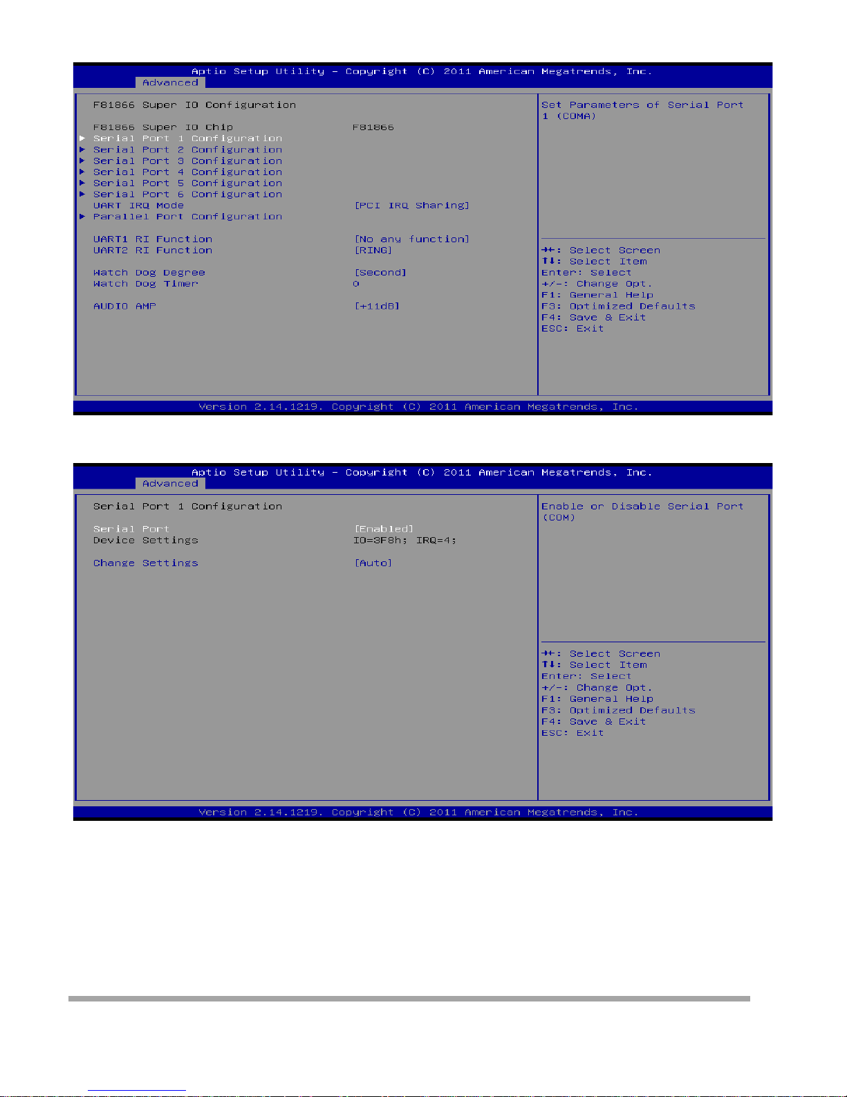
F81866 Super IO Configuration
Serial Port 1 Con fi guration
Serial Port
This item enables or disables Serial Port (COM).
Options: Enabled ( Defa ult) / Disabled
Change Settings
This item sele ct s an optimal setting for Super IO device.
Options: Auto (Default) / IO=3F8h; IRQ=4 / IO=3F8h; IRQ= 3, 4, 5, 6, 7,10, 11, 12 / IO=2F8h; IRQ= 3,
4, 5, 6, 7,10, 11, 12 / IO=3E8h; IRQ = 3, 4, 5, 6, 7,10, 11, 12 / IO=2E8h; IRQ= 3, 4, 5, 6, 7,10, 11, 12
30
Page 32
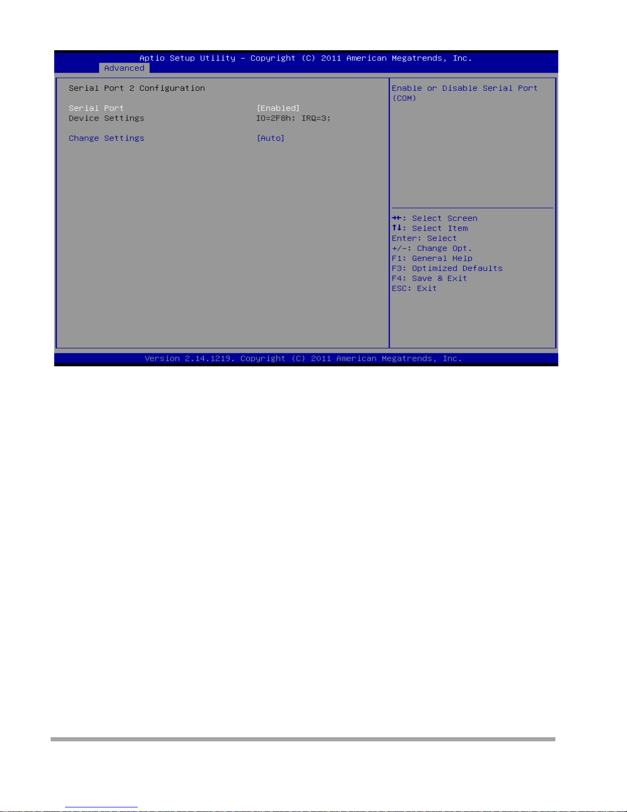
Serial Port 2 Con fi guration
Serial Port
This item enables or disables Serial Port (COM).
Options: Enabled ( Defa ult) / Disabled
Change Settings
This item sele ct s an optimal setting for Super IO device.
Options: Auto (Default) / IO=2F8h; IRQ=3 / IO=3F8h; IRQ= 3, 4, 5, 6, 7,10, 11, 12 / IO=2F8h; IRQ = 3,
4, 5, 6, 7,10, 11, 12 / IO=3E8h; IRQ = 3, 4, 5, 6, 7,10, 11, 12 / IO=2E8h; IRQ= 3, 4, 5, 6, 7,10, 11, 12
31
Page 33
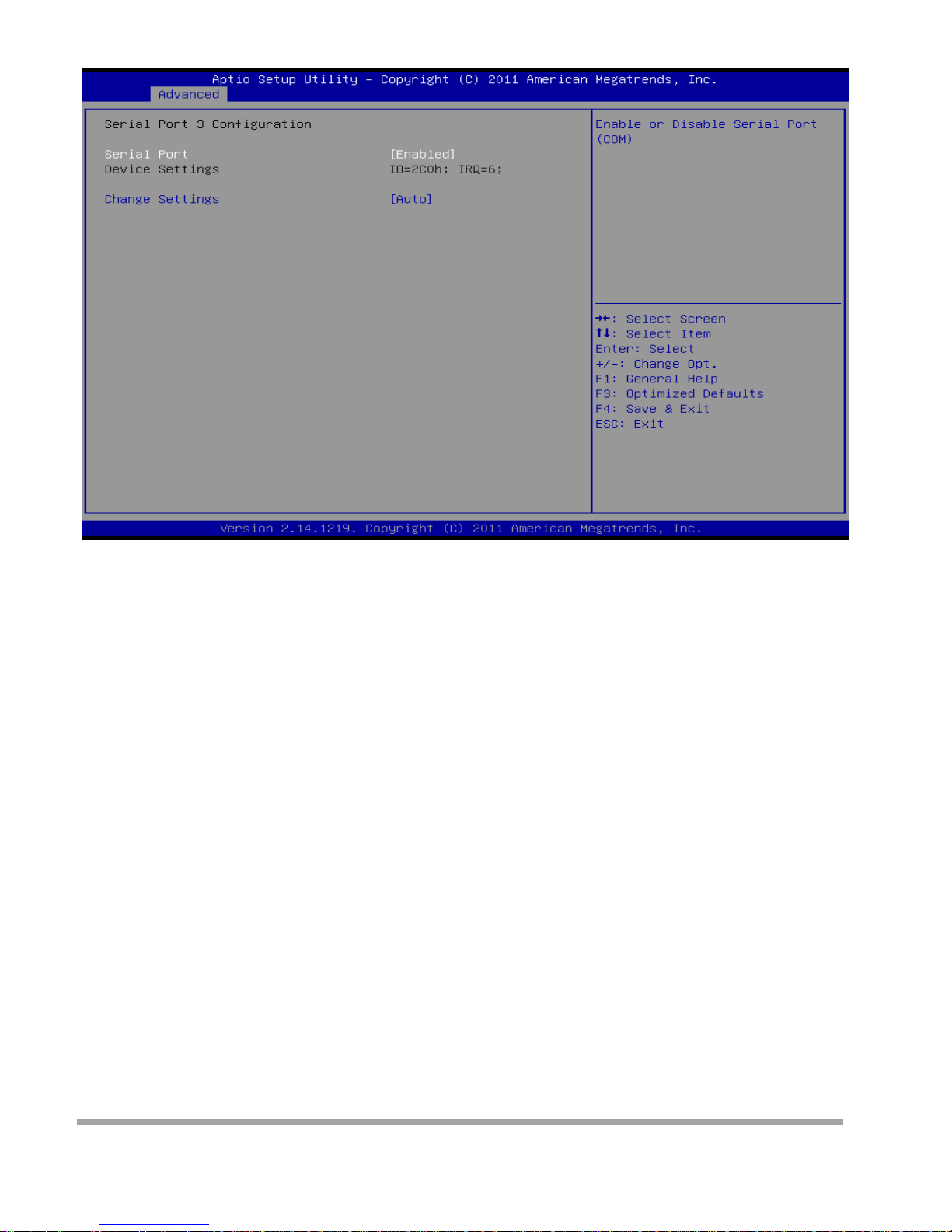
Serial Port 3 Con fi guration
Serial Port
This item enab les or disables Serial Port (COM).
Options: Enabled ( Defa ult) / Disabled
Change Settings
This item sele ct s an optimal setting for Super IO device.
Options: Auto (Default) / IO=2C0h; IRQ=6 / IO=3F8h; IRQ=6 / IO=2F8h; IRQ=6 / IO=2C0h; IRQ=6 /
IO=2C8h; IRQ=6 / IO=2D0h; IRQ=6 / IO=2D8h; IRQ=6
32
Page 34
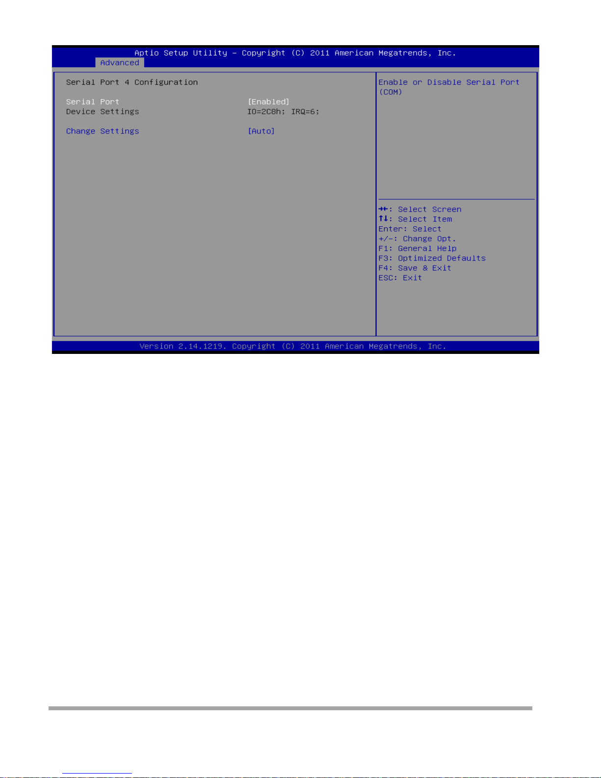
Serial Port 4 Con fi guration
Serial Port
This item enables or disables Serial Port (COM).
Options: Enabled ( Defa ult) / Disabled
Change Settings
This item sele ct s an optimal setting for Super IO device.
Options: Auto (Default) / IO=2C8h; IRQ=6 / IO=3F8h; IRQ=6 / IO=2F8h; IRQ=6 / IO=2C0h; IRQ=6 /
IO=2C8h; IRQ=6 / IO=2D0h; IRQ=6 / IO=2D8h; IRQ=6
33
Page 35
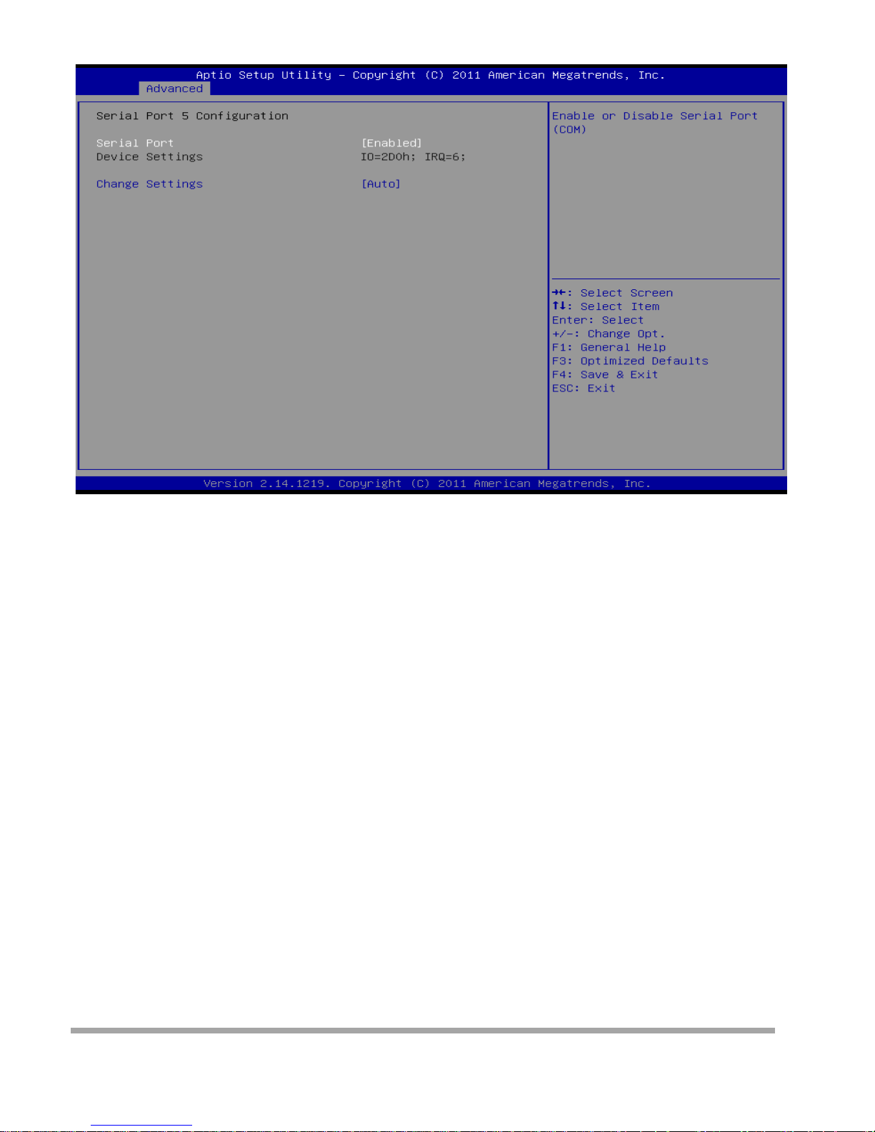
Serial Port 5 Con fi guration
Serial Port
This item enables or disables Serial Port (COM).
Options: Enabled (Default) / Disabled
Change Settings
This item sele ct s an optimal setting for Super IO device.
Options: Auto (Default) / IO=2D0h; IRQ=6 / IO=3F8h; IRQ=6 / IO=2F8h; IRQ=6 / IO=2C0h; IRQ=6 /
IO=2C8h; IRQ=6 / IO=2D0h; IRQ=6 / IO=2D8h; IRQ=6
34
Page 36
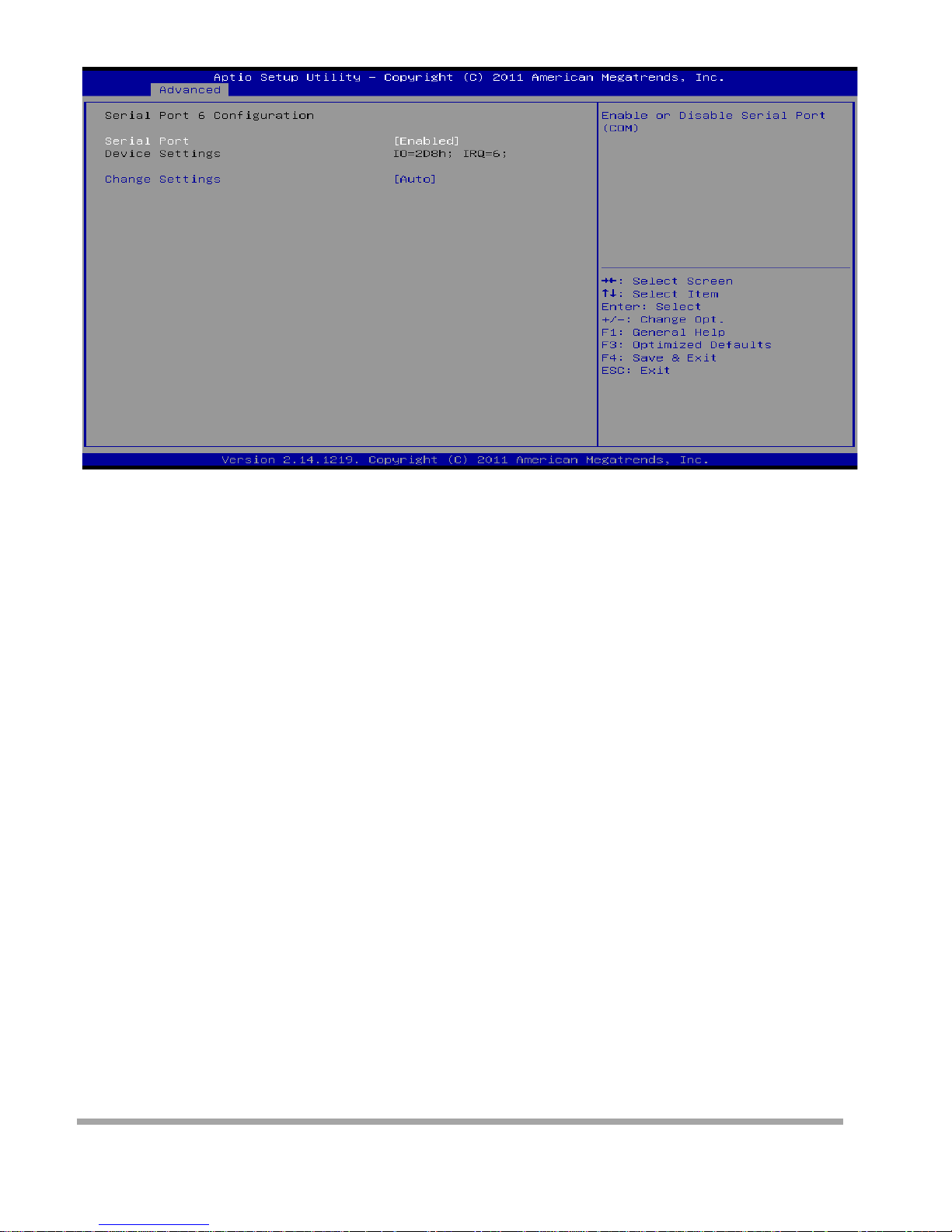
Serial Port 6 Configuration
Serial Port
This item enables or disables Serial Port (COM).
Options: Enabled ( Defa ult) / Disabled
Change Settings
This item sele ct s an optimal setting for Super IO device.
Options: Auto (Default) / IO=2D8h; IRQ=6 / IO=3F8h; IRQ=6 / IO=2F8h; IRQ=6 / IO=2C0h; IRQ=6 /
IO=2C8h; IRQ=6 / IO=2D0h; IRQ=6 / IO=2D8h; IRQ=6
UART I RQ Mode
This item allow s you to dete rmi ne PCI I RQ shar i ng for OS (EX. Windows) ISA IRQ for DOS. Options:
PCI IRQ Sharing (Default) / ISA IRQ
35
Page 37
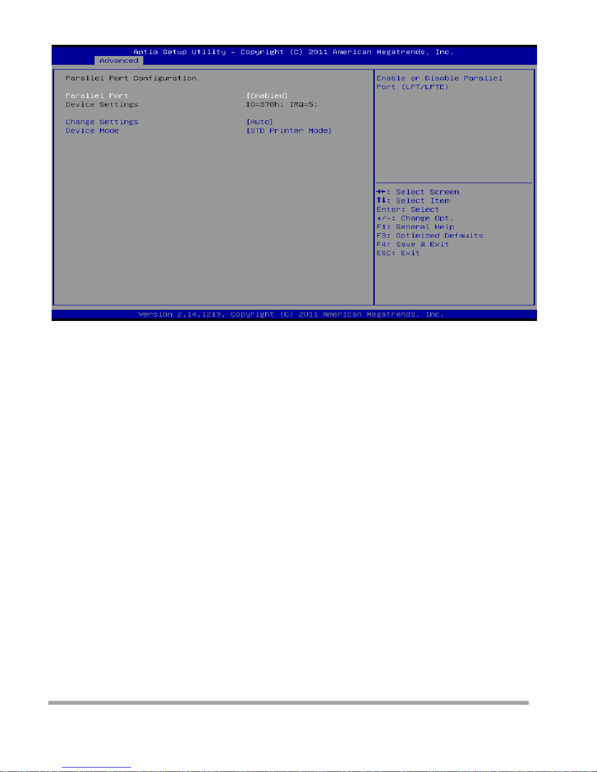
Parallel Port Config uration
Parallel Port
This item enab les or disables Parallel Port (LPT/LPTE).
Options: Enabled ( Defa ult) / Disabled
Change Settings
This item allow s you to sele ct an optimal setting for Super IO devi ce.
Options: Auto ( Defa ult) / IO=378h; IRQ=5 / IO=378h; I RQ=5, 6, 7, 10, 11, 12 / IO=278h; IRQ=5, 6, 7, 10,
11, 12 / IO=3BCh; IRQ=5, 6, 7, 10, 11, 12
Device Mode
This item allow s you to dete rmi ne how the parallel port should functio n.
Options: STD Printer Mode (Default) / SPP Mode / EPP-1.9 and SPP Mode / EPP-1.7 and SPP Mode /
ECP Mod e / ECP and EPP 1 .9 Mode / ECP and EPP 1.7 Mode /
UART1 RI Function
This item sele ct s CO M1 port pin 9 functio n.
Options: RING (Default) / +5V / +12V
UART2 RI Function
This item sele ct s CO M2 port pin 9 functio n.
Options: No any function (Default) / +5V / +12V
Watch Dog Degree
This item allow s you to dete rmi ne t he funct io nal degree of Watch Dog.
Options: Second ( Default) / Minute
Wat ch Dog Ti me r
Options: 0 for disabled ( Defa ult) / Min=1, Max =65536
36
Page 38
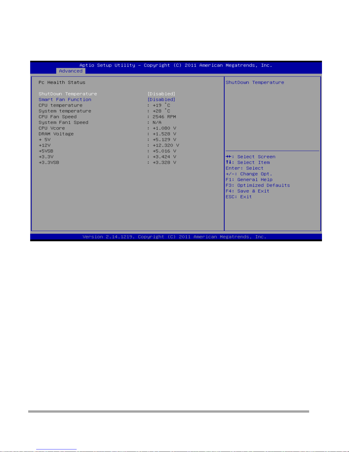
Audio AMP
This item adjusts external audio amplifier.
Options: +11dB ( De fault) / +14dB / +19dB / +25dB
F81866 H/W Monitor
Shutdown Temperature
This item allow s you to set up the CPU shutd ow n Tem per at ure .
Options: Disabled (Default) / 70°C/158°F / 75°C/167°F / 80°C/176°F / 85°C/185°F / 90°C/194°F Smar t
Fan Fun ct ion
This item allow s you to control the CPU Smart Fan functio n.
Options: Di sabled ( De fa ult ) / Enabled
37
Page 39
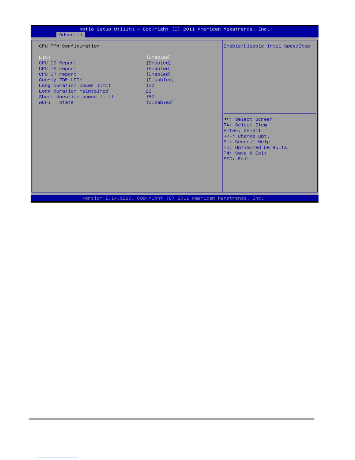
CPU PPM Configuration
EIST
This item enab les/disables Intel SpeedStep function.
Options: Enabled ( Defa ult) / Disabled
CPU C3/ C6 / C7 report
This item enab les/disables C3 (ACPI C2)/ C6 (ACPI C3)/ C7 (ACPI C3) r eport to OS. Options:
Enabled (Default) / Disabled
Confi g TDP LO CK
This item allows you lock the config TDP control reg i ster.. Optio ns : Disab led ( Defa ult) / Enabled
Long du ration power limit
Long duration power limit in watts, 0 means factory default Options: 120 (Default)
Long duration maintained
Time window which the long duration power is maintained Options: 28 (Default)
Short durat i on pow er l i mit
Short duration power limit in watts, 0 means factory default Options: 150 (Default)
ACPI T State
This item allows you enables/ disables ACPI T state support. Options: Disabled (Default) / Enabled
38
Page 40
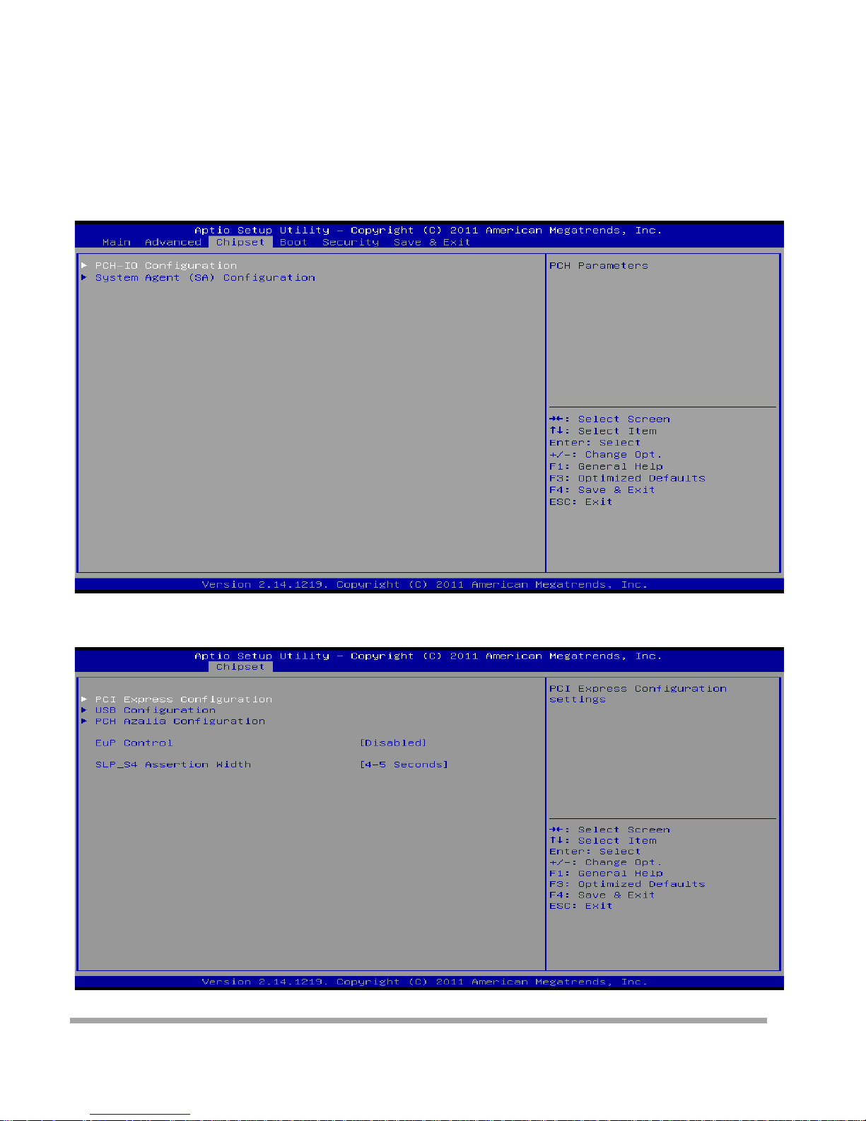
Chipset Menu
This sectio n descr ibes configuring the PCI b us system. PCI, or Personal Computer Inter connect, is a
system which allows I/O devices to operate at speeds nearing the speed of the CPU its el f uses
when communicating with its own spe cial components.
▶
Note
» Beware of that setting inappropriate values i n items of this m enu may cause s
PCH-IO Configuration
39
Page 41
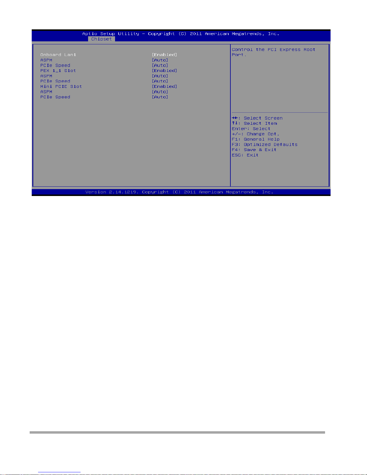
PCI Express Configuration
Onboard Lan1 / PEX 1_1/ Min i PCIE Slot
This item controls the PCI Express Root Port.
Options: Enabled (Default) / Disabled
ASPM
This item sets PCI Expre ss Active State Power Managem ent setti ngs. Options: Auto(De fault) / Disabled /
L0s / L1 / L0sL1
PCIe Speed
This item selects PCI Express port speed.
Options: Auto (Default) / Gen1 / Gen2
40
Page 42
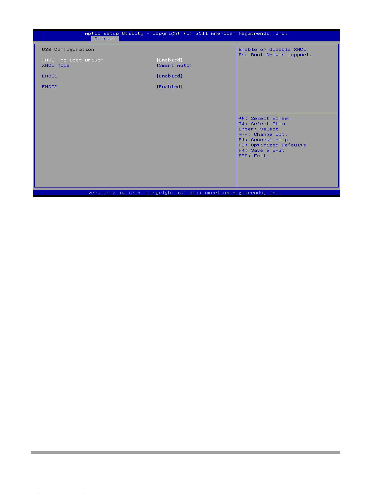
USB Configuration
XHCI Pre-Boot Drive r
This item enab les or disables XHCI Pre-Boot Dri ve r suppo r t.
Options: Enabled ( Defa ult) / Disabled
XHCI Mode
This item sets the mode of operation of XHCI controller .
Options: Sma rt Auto ( Default ) / Auto / Enabled / Disabled
EHCI1/2
This item co ntrols the USB EHCI (USB2.0) functio ns. O ne EHCI cont r oll er m ust always be enabled.
Options: Enabled ( Defa ult) / Disabled
41
Page 43
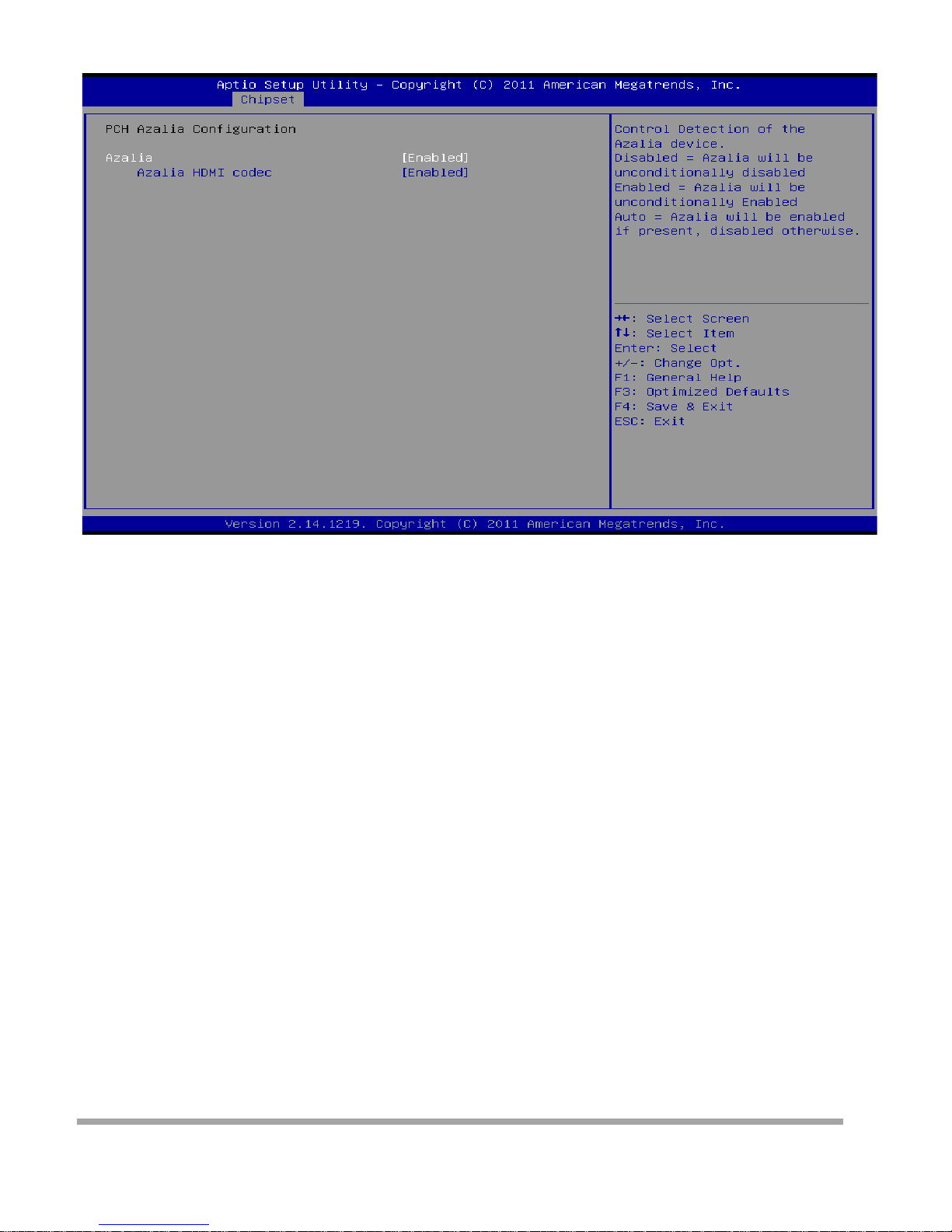
PCI Azalia Configuration
Azalia
This item controls detection of the Azalia device.
Disabled = Azalia wi ll be unco ndi tio nal ly disabled.
Enabled = Azalia will be unconditionall y Enabl ed.
Auto = Azalia will be enabled if present, disabled otherwise.
Options: Enabled ( Defa ult) / Disabled
Azalia HDMI codec
This item enab les or disables internal HDMI codec Port for Azalia
Options: Enabled ( Defa ult) / Disabled
EuP Control
When EuP Enable d, System meets EuP requirement.
Options: Di sabled ( De fa ult ) / Enabled
SLP_S4# Min. Assertion Width
Options: 4 to 5 seconds (Default) / 1 to 2 seconds / 3 to 4 seconds / 2 to 3 seconds / Disabled
42
Page 44
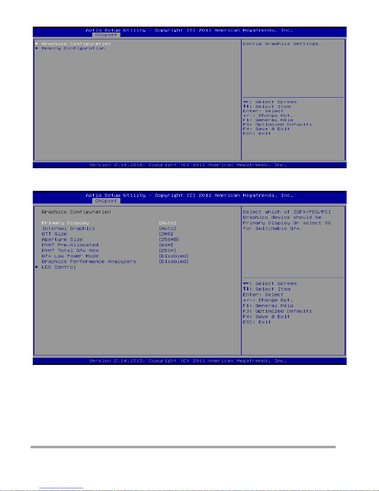
System Agent (SA) Configu ration
Graphics Configuration
Primary Display
This item selects which of IGFX/PEG/PCI Graphics device should be Primary Display or select SG for
Switchable Gfx.
Options: Auto (Default) / IGFX / PEG
43
Page 45

Intern al Graphi cs
Th is item ke eps IGD enabl ed based on the s et up opt ions.
Options: Auto (Default) / Disabled / Enabled
GTT Size
This item selects GTT Size.
Options: 2MB (Defa ult) / 1MB
Apertu re Size
This item sele ct s Apera t ure Size.
Options: 256MB (De fa ult ) / 128MB / 512MB
DVMT Pre-Allocated
This item sele ct s DVMT 5.0 Pre-Allocated (Fixed ) Graphi cs Memory s ize use d by
the Internal Graphics Device.
Options: 64M (Default) / 32M / 96M / 128M / 160M / 192M / 224M / 256M /
288M / 320M / 352M / 384M / 416M / 448M / 480M / 512M / 1024 M
DVMT Total G fx Mem
This item sele ct s DVMT5.0 To t al Graphic Memory size used by
the Inter nal Grap hics Device. Options: 256MB (De fa ul t) / 128MB / MAX
Gfx Low Power Mode
This option is applicable for SFF only
Options: Di sabled ( De fa ult ) / Enabled
Graphics Performan ce A nalyzers
Th is item is en ables/ disa bles Intel gr aphics perfo rmance analy zers c ounter s .
Options: Di sabled ( De fa ult ) / Enabled
44
Page 46
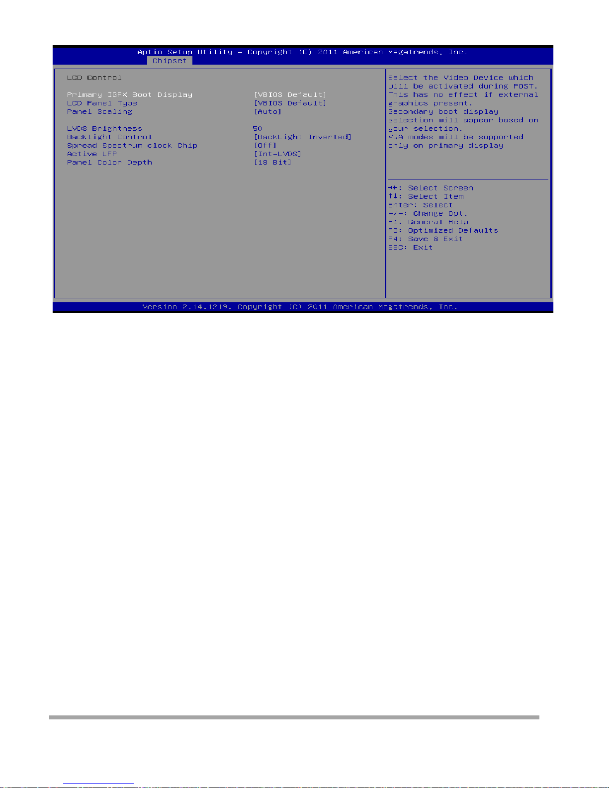
LCD Control
Prima ry IGFX Boot Display
This item sele ct s the video device which will be activated d uring POST. This has no effect if external
graphics present.
Options: VBIOS De fault (Default) / CRT / LVDS / HDMI (optional)
LCD Panel Type
This item sele ct s the LCD panel used by Inter nal Graphics Device by selecting
the a ppropriat e setup item.
Options: VBI O S Default ( Default) / 640 x 480 / 800 x 600 / 1024 x 768 / 1280 x 1024 /
1400 x 1050(RB) / 1400 x 1050 / 1600 x 1200 / 1366 x 768 / 1680 x 1050 / 1920 x 1200 /
1440 x 900 / 1600x 900 / 1024 x 768 / 1280 x 800 / 1920 x 1080 / 2048 x 1536
Panel Scali ng
This item sele ct s the LCD panel s cali ng opt io n used by the Internal Graphics Device.
Options: Auto (Default) / Force Scaling / Off
LVDS Brightness
This item sele ct s the LCD panel brightness perc entag e.
45
Page 47

Backlight Control
This item sele ct s Back Light Control Setting
Options: BackLight Inverted (Default ) / BackLight Normal
Spread Spectru m clock Chip
>>Hardware: Spread is controlled by chip; >>Software: Spread is control led by BIOS Optio ns: Off
(Default) / Hardware / Software
Active LFP
This item sele ct s the Active LVDS Configuration. No LVDS: VBIO S do es not enable LVDS; Int-LVDS:
VBIOS enabl es LVDS driver by integrated encoder.
Options: In t-LVDS (Defa u lt) / No LVDS
Panel Color Dept h
This item sele ct s the LFP Panel Color Depth
Options: 18Bit ( Defa ul t) / 24Bit
46
Page 48
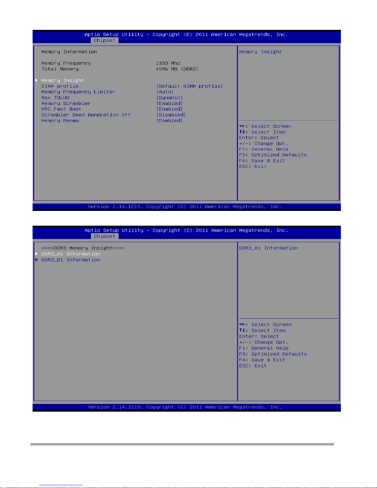
Memory Configuration
Memory Insight
DDR3_A1/B1 Information
These items display SPD information of DDR3 memory.
47
Page 49
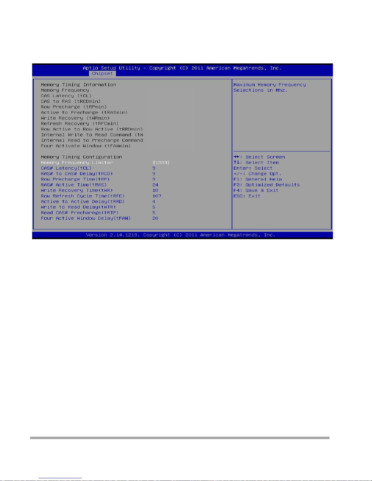
DIMM Pro file
Select DIMM timing profile that should be used.
Options: Default DIMM profile (Default) / Custom Profile
Custom Profile Control
CAS# Laten cy (tCL)
This item allow s you to sele ct CAS Lat ency of DDR3.
Options: 9 (Default) / 3 ~ 15
RAS# to CAS# Delay (tRCD)
This item allow s you to sele ct Row Address to Column Addre ss Delay o f DDR3.
Options: 9 (Default) / 3 ~ 15
Row Precharge Time (tRP)
This item allow s you to sele ct Row Pr echarge Time of DDR3.
Options: 9 (Default) / 3 ~ 15
RAS# Active Ti me (tRAS)
This item allows you to select Row Active Time of DDR3.
Options: 24 (Default) / 9 ~ 63
Write Recovery Time (tWR)
This item allow s you to sele ct I nte r nal Write to Read Comm and Delay of DDR3.
Options: 10 (Default) / 3 ~ 31
48
Page 50

Row Refresh Cycle Time (t RF C)
This item allows you to select Minimum Refresh Recovery Time of DDR3.
Options: 107 (De fa ult) / 15 ~ 255
Active t o Acti ve Delay (tRRD)
This item allow s you to sele ct Row Act ive to Row Active Delay of DDR3.
Options: 4 (Default) / 4 ~ 15
Write to Read Delay (tWTR)
This item allow s you to sele ct I nte r nal Write to Read Comm and Delay of DDR3.
Options: 5 (Default) / 3 ~ 31
Read CAS# Precharge ( t RTP)
This item allow s you to sele ct Rea d to Pre charge Dela y of DDR3.
Options: 5 (Default) / 4 ~ 15
Four Active Win dow Delay (tFAW)
This item allow s you to sele ct Fo ur Active Window Delay of DDR3.
Options: 20 (Default) / 4 ~ 63
Memory Frequency Limiter
Maximum Memory Frequency Selections in MHz.
Options: Auto (Default) / 1067 / 1333
Max TOLUD
This item sets maximum value of TOLUD. Dynamic assignment would adjust TOLUD automat ically
based o n largest MMIO le ngt h of ins ta lled grap hi c controller.
Options: Dynamic (Default) / 1 GB / 1.25 GB / 1.5 GB / 1.75 GB / 2 GB / 2.25 GB / 2.5 GB / 2.75 GB / 3
GB / 3.25 GB
Memory Scrambler
This item enab les or disables memory scramble r suppor t.
Options: Enabled ( Defa ult) / Disabled
MRC Fast Boot
This item enab les or disables MRC Fast Boot.
Options: Enabled ( Defa ult) / Disabled
Scrambler Seed Gen erati on Off
This item sets cont rol memory scrambler seed ge nera tion.
Enable – do not generation scrambler seed. Disable – generation scrambl er seed a lways. Options:
Disabled ( Default ) / Enabled
Memory R emap
This item enab les or disables memory remap abo ve 4G.
Options: Enabled (Default) / Disabled
49
Page 51
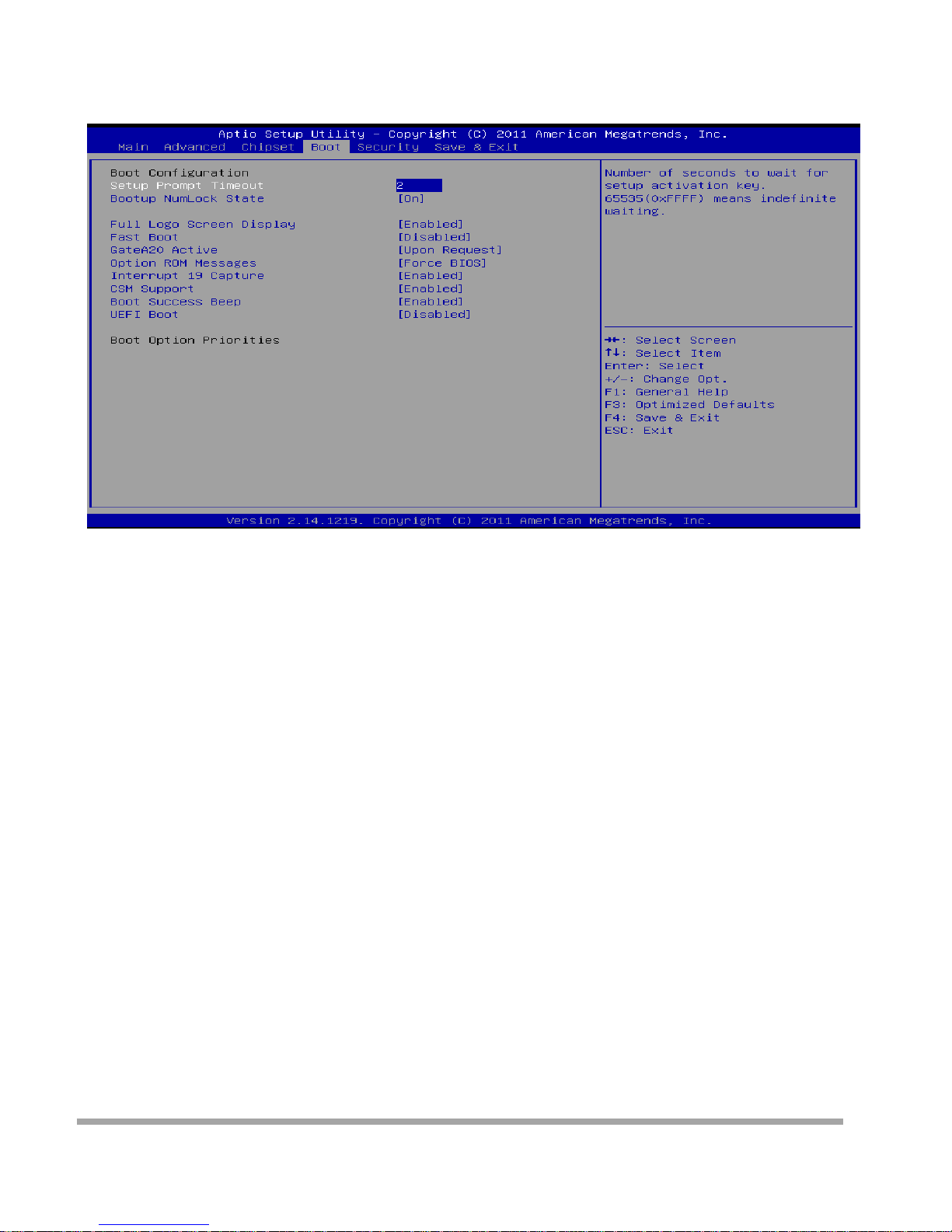
Boot Menu
This menu allows you to setup the system boot optio ns
.
Setup Pro mpt Timeout
This item sets number of seconds to wait for setup activation key.
Options: 2 (Default)
Bootu p NumLock State
This item selects the keyboard NumLock state.
Options: On (Default) / Off
Full Screen LOGO Display
This item allows you to enable/disable Full Scree n LO GO Show funct i on.
Options: Enabled (Default) / Disabled
Fast Boot
This item allows you to enable/disable Full Scree n LO GO Show funct i on.
Options: Disabled (Default) / Enabled
Skip VGA
If enabled, BIOS will skip EFI VGA driver.
Options: Disabled (Default) / Enabled
Skip USB
If enabled, USB devices will not be available until after OD boot. If disabled, USB device will be
ava ilable before OS bo ot.
Options: Disabled (Default) / Enabled
Skip PS2
If enabled, PS2 devices will be skipped.
Options: Disabled (Default) / Enabled
GateA20 Active
50
Page 52

Upon Request – GA20 ca n be disabled using BIOS services. Always – do not allow disabling GA20;
this optio n is useful when any RT code is executed above 1MB
Options: Upon Request (Default) / Always
Option RO M Messages
This item sets the display mode for Option ROM.
Options: Force BIOS (Default) / Keep Current
Interrupt 19 Captu re
Interrupt 19 is the software interrupt that handles the boot disk function.
When set to Enab led , t his item allows the option ROMs to trap inter r upt 19.
Options: Enabled (Default) / Disabled
CSM Support
This item e nables / disables CSM Support. If Auto is sele c ted , ba sed on OS, CSM will be enabled /
dis abled au tomat i cally .
Options: Enabled (Default) / Disabled / Auto
Boot Success Beep
When this item is set to Enabled, BI O S will let user k now boo t success wi t h beep.
Options: Enabled (Default) / Disabled
UEFI Boot
This opt io n enab le s/di sable s boot from the UEFI Devices.
Options: Disabled (Default) / Enabled
51
Page 53
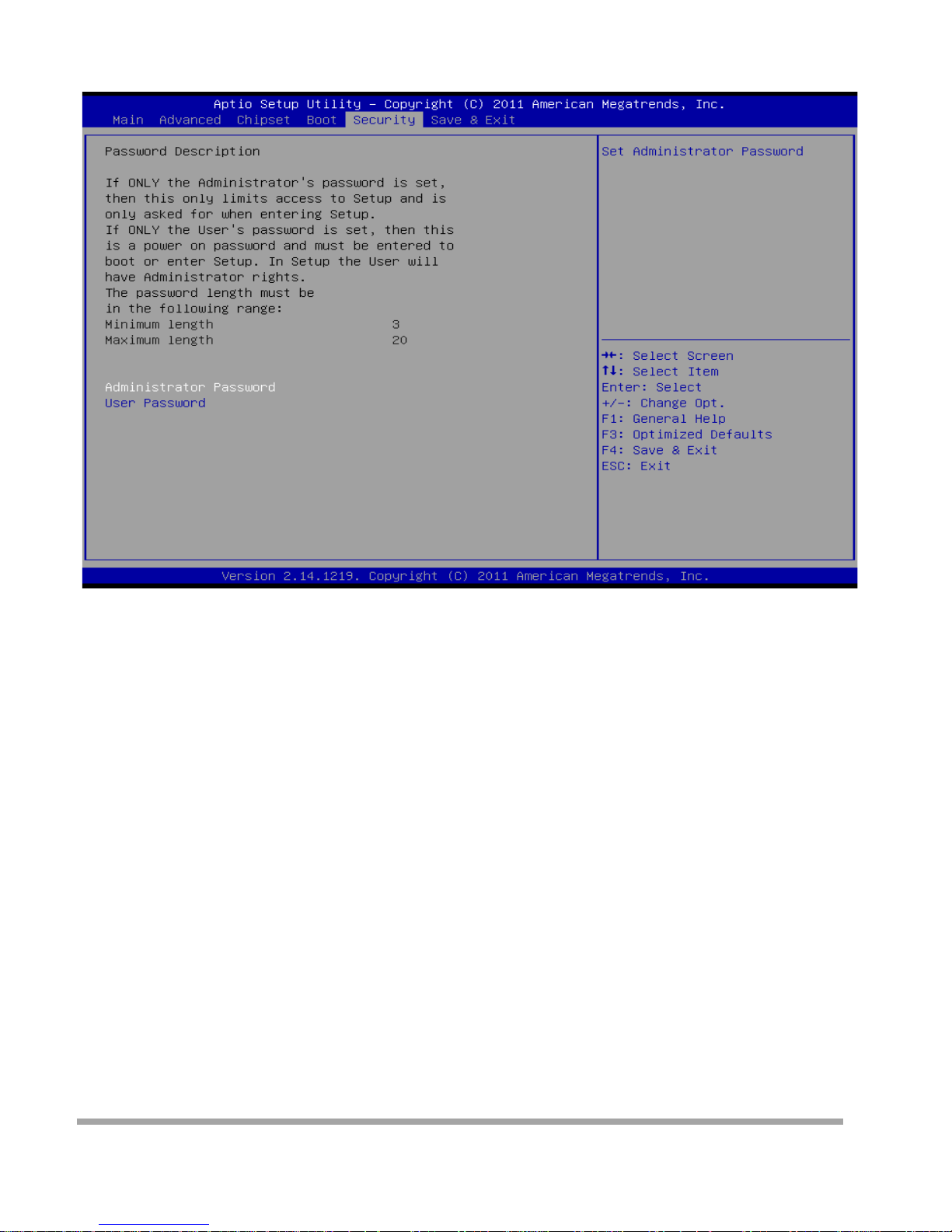
Security Menu
Administrator Password
This item sets Admi nistrator Password.
User Password
This item sets Use r Pa ssword.
52
Page 54
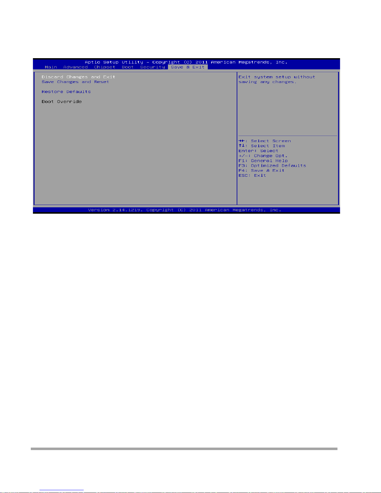
Exit Menu
This menu allows you to load the optimal default settings, and save or discard the changes to
the BIOS items.
Discard Changes and Exit
Abandon all changes made during the current session and exit setup.
Save Changes and Reset
Reset the system after saving the changes.
Restore Defaults
This sele ctio n allows you to reload the BIOS whe n problem occur s dur i ng system boot i ng seq uence.
These configurations are factory settings optimized for this system.
53
Page 55
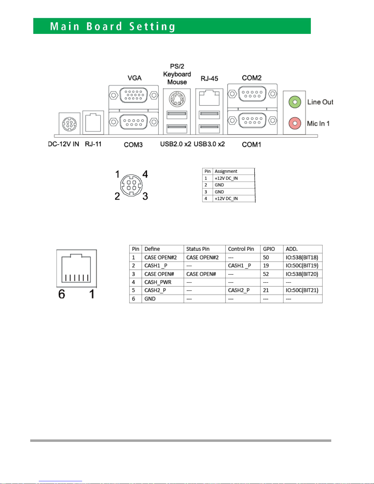
Rear P a ne l Connect ors
DC-12V Input Connector
RJ-11 pi n defi ne
6
54
Page 56
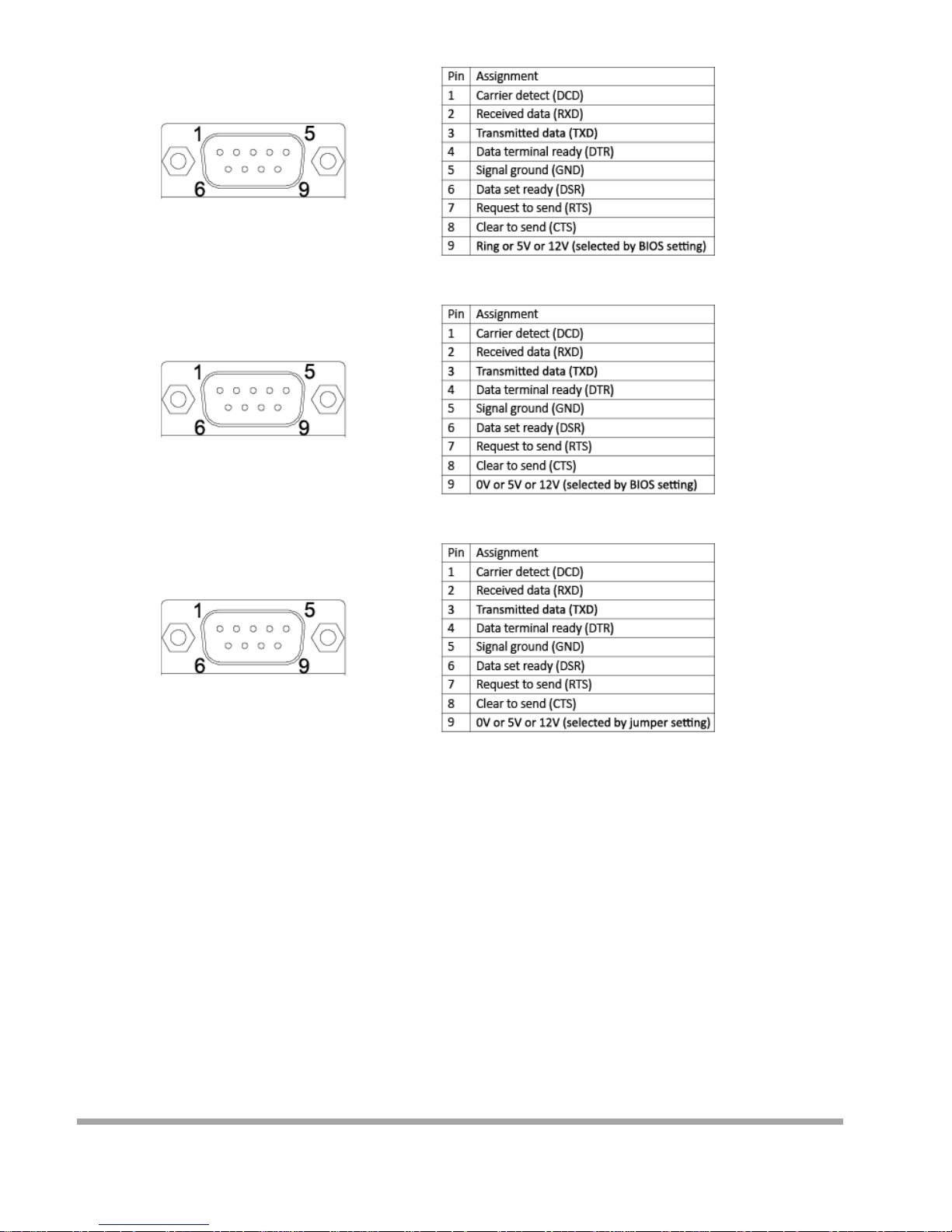
COM1 Connector
COM2 Connector
COM3 Connector
▶
Note
»» Note1: COM1/2 voltage selection is controlled by BIOS setup. Please see page-34 for detail se tting.
»» Note2: C OM1 RS-232/422/485 selection is controlled by JSEL1/JSEL2. Please see page-14 for detail setting.
»» Note3: C OM3 voltage selection is controlle d by JPC3. Please see page-15 for detail setting.
55
Page 57
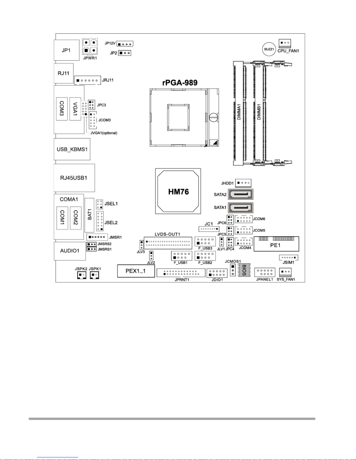
Motherboard Layout
▶
Note
»» ■ represents the 1st pin.
56
Page 58
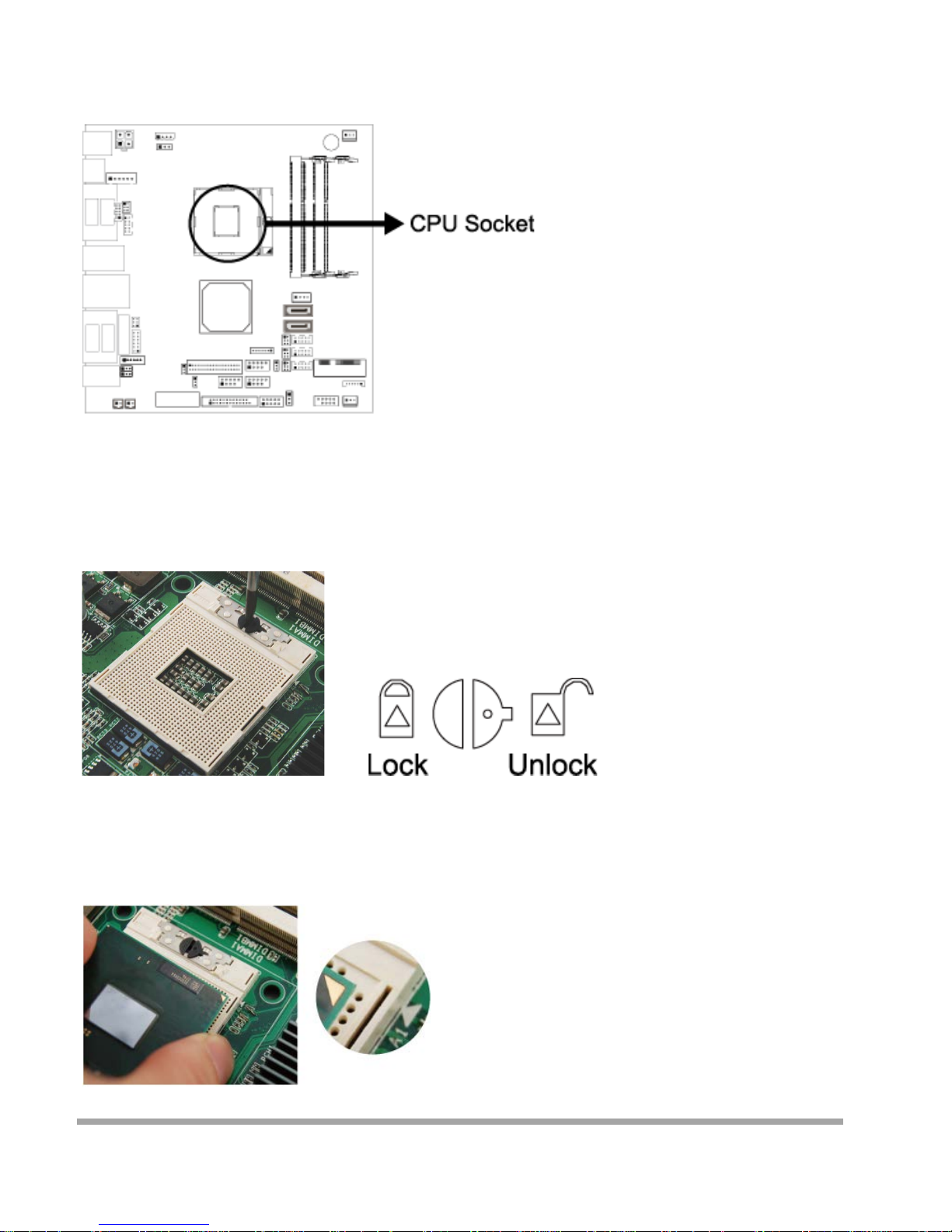
Installing Central Processing Unit (CPU)
Step 1: Loca te the CPU sock et on the mot herbo ard
▶
Note
»» Do not touch processor contacts to prevent damaging th e CPU.
Step 2: Using a screwdriver, disengage ( Unlock ) the socket actuator, as shown in figure below.
Step 3: Align the gold tria ngle on the CPU with the similar mar king on the soc ket. If the pro cessor do es
not drop completely into the socket, turn the socket actuator to the open position until the processor
drops comp letely in.
57
Page 59
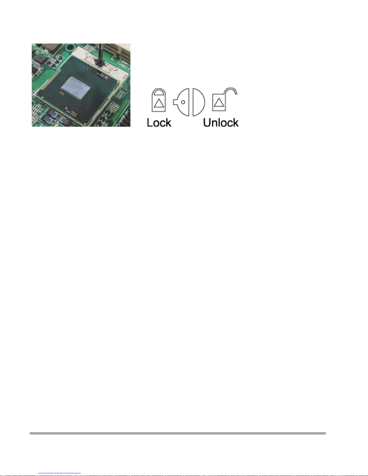
Step 4: While gently holding the processor down with your finger, secure the processor in the socket with
a screwdriver by turning the socket actuator to the “Lock” position.
▶
Note
»» The CPU fits only in one correct orientation. Do not force the CPU into the socket to prevent
damaging t he CPU.
Install a Cooler
The system m ust not be operated without a coo le r (heat sink and fan) to provide the necessarily cooling.
Install t he cooli ng uni t suppl ied as follows:
1. Install t he correct CPU as described above.
2. Align the screw holes of the cooler rear retention bracket with the mounting holes on the
underside of the motherboard, located at the four corners of the CPU location.
Ins ert into the holes and turn the motherboard ov er .
3. Place t he cooler assembly on top of the CPU with the cooling fins al igned with the memory
slots. This will allow the fan to provide cooling the chipset heat sink. Align the screws with the screw
hol es of the r ear retention brac ket.
4. Tighten each screw halfway to secure the cooler assembly to the motherboard. Then
gradual l y tig hten all fo ur screw s . Do not full y tig hte n the fir st screw befo re pa rtially
tighteni ng the ot her screws as this may apply uneven press ure to the CPU, causing damage.
▶
Note
»» Be careful not to touch the the rma l pad on the underside of the heatsi nk. Thi s pad is made o f
thermal compound and is deformable. It is designed to make optimal thermal contact with the CPU.
No additional thermal compound is req uired.
»» Make sure that good t hermal co nta ct i s made betwee n the processor and heat sink. Insufficient
contact or incorrect use of heat sink, fan, or thermal compound can cause the processor to overheat,
which may crash the system or cause permanent damage to the CPU.
»» Do not forget to co nnec t the CPU fan connector.
»» For proper installation, please kindly refer to the installation manual of your CPU cooler.
58
Page 60
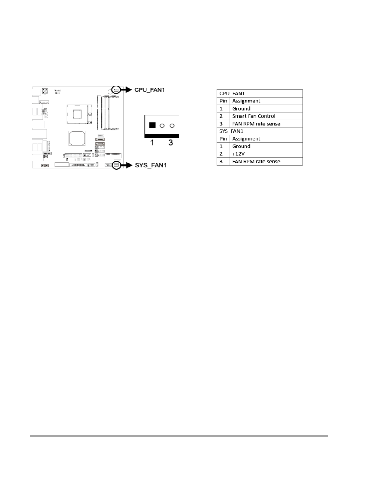
Connect Cooling Fans
These fan headers support cooling -fans built in the computer. The fan cable and connector may be
different according to the fan manufacturer. Connect the fan cable to the connector while matching the
black wire to pin#1.
CPU_FAN1: CPU fan header
SYS_FAN1: Syste m fan header
▶
Note
»» System Fan Headers support 3-pin head connectors. When connecting wi t h wires onto connectors,
ple ase not e t hat the red wire is the positive and should be connected to pin#2, and the black wire is
Ground and should be connected to GND.
59
Page 61
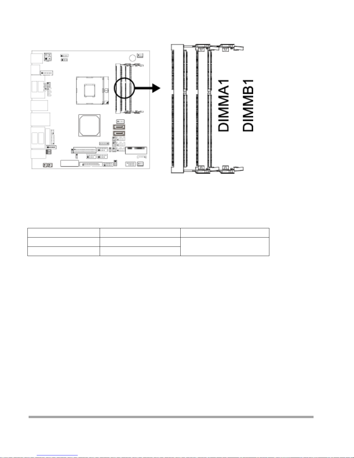
Installing System Memory
DIMMA1/B1: Memory Module (204pin SO-DIMM)
▶
Note
1. Align a DIM M on the slot such tha t the no t ch on t he DIMM matches the break on the Slot.
2. Inse r t the DIMM fi r m l y into the slot until the retaining chip snap ba c k in place and the
DIMM is properly seated.
DIMM Socket Location DDR3 Modul e Total Mem ory S ize
DIMMA1 512MB/1GB/2GB/4GB Max is 8GB
DIMMB1
512MB/1GB/2GB/4GB
60
Page 62
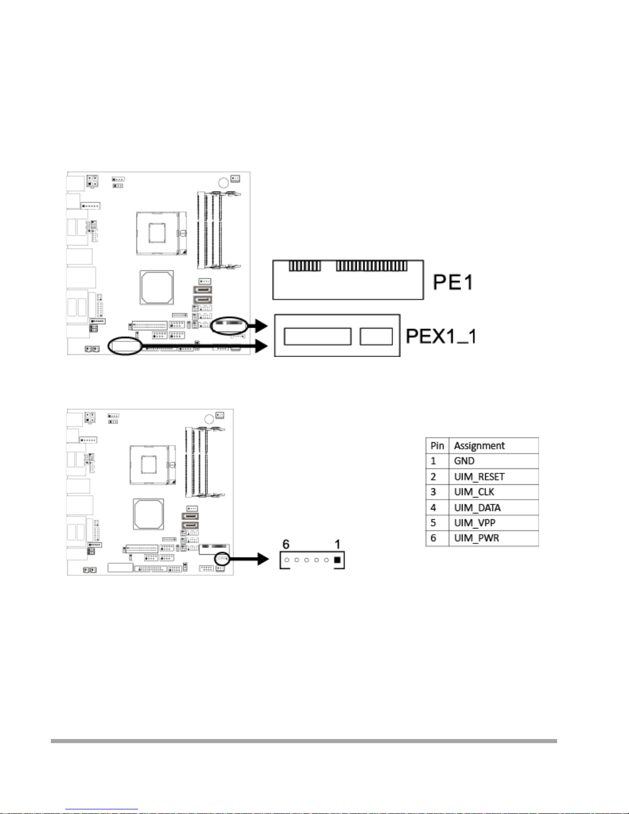
Expansion Slots
PEX1_1: PCI-Express x1 Slot
•PCI-Express 2.0 complia nt.
•Data transfer bandwidth up to 500MB/s per direction; 1GB/s in total.
•PCI-Express supports a raw bit-rate of 2.5G b/ s on th e data pins.
PE1: Min i PCI-E Slot ( mSATA func tion is optional)
This mainboard is equipped with 1 Mini PCI-E Slot.
JSIM1: SIM card header
This mainboard is equipped with one SI M card header for Mini PCI-E Slot.
61
Page 63
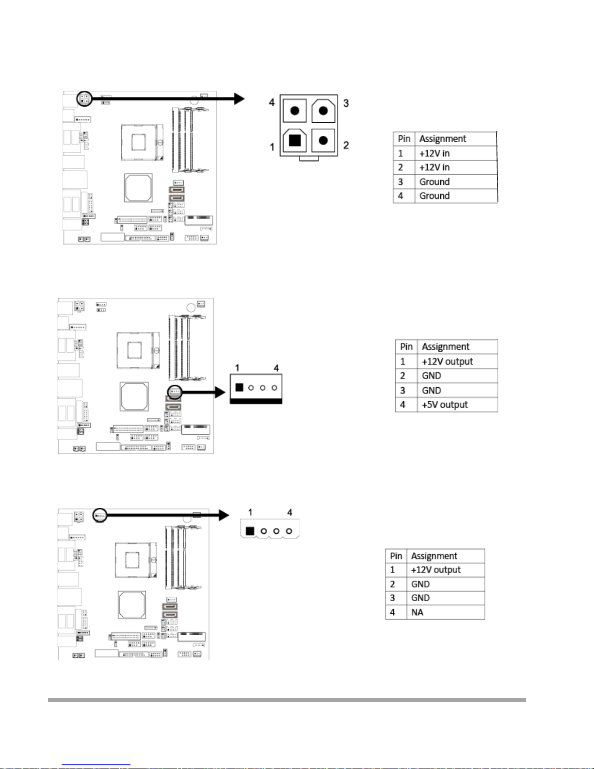
Power Supply
JPWR1: ATX Power Source Connect or (4-pin)
This connector provides or +12V input to system power circuit.
JHDD1: HDD Power Con nector
This connector provides power connection of SATA devices.
JP12V: 12V Outpu t Pow er Conn ect or
This connector provides power connection of 12V output.
62
Page 64
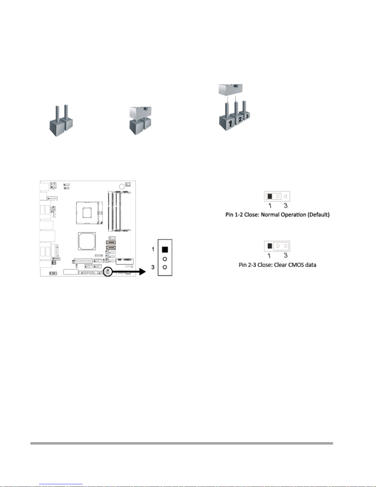
Jumpers / Headers / Connectors
Jumper Setting
The illustration shows how to set up jumpers . When the j umpe r cap is pla ced on pins, the jumpe r is
“close”, if not, that means the jumper is “open”.
Pin opened Pin closed Pin 1-2 closed
JCMOS1: Clear CMOS Jumper
Placing the jumper on pin2-3 allows user to restore the BIOS safe setting and the CMOS data.
Please care fully follow the procedures to avoid damaging the motherboard.
Clear CMOS Procedures:
1. Remove AC pow er lin e .
2. Set the jumper to “Pin 2-3 close”.
3. Wait for five seconds.
4. Set the jumper to “Pin 1-2 close”.
5. Power on the AC.
6. Res et your desired password or c l ear the CMOS data.
63
Page 65
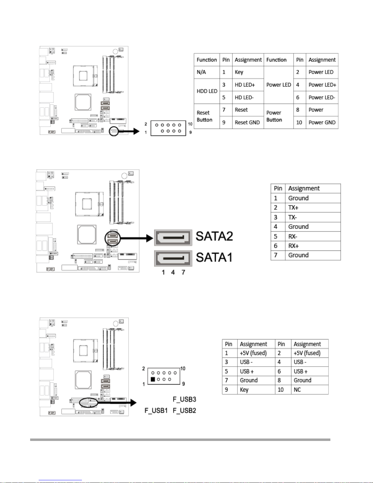
JPANEL1: Front Panel Header
This 10-pin header includes Power -on, Reset, HDD LED, and Power LED connection. It allow s user
to connect the system case’s front panel swit ch functions.
SATA1/SATA2: Serial ATA 6.0 Gb/s Connectors
These connectors support the thin Serial ATA cable for primary internal storage devices.
F_USB1/2/3: USB 2. 0 Header
The mainboar d pro v ide s USB 2.0 pi n header . Each header allows you to conne ct 2 additio nal
USB 2.0 ports.
64
Page 66
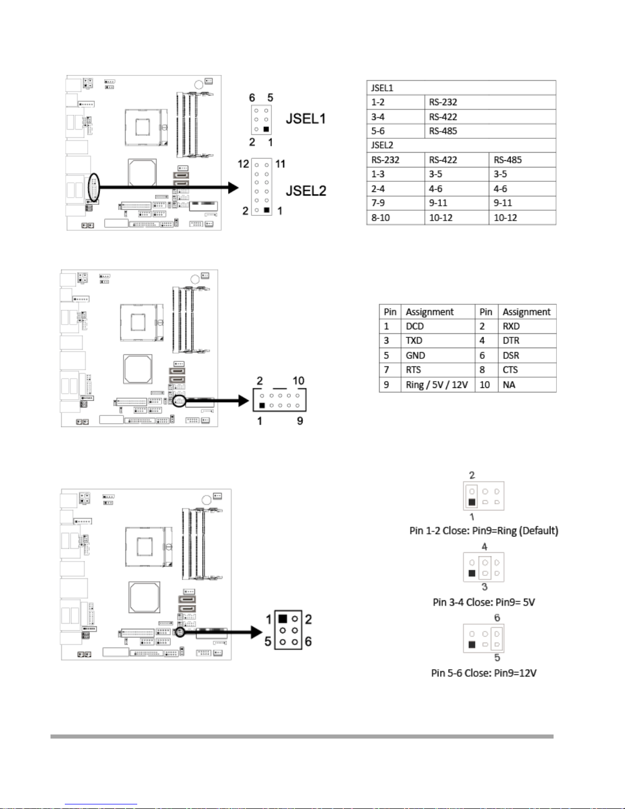
Serial Port Connectors & Headers
JSEL1/JSEL2: RS-232/ 422/485 Sw i t ch Headers for COM1
The header s determine that COM1 belongs to RS-232 (De fa ult), 422, or 485.
JCOM4: Serial Port Header
JPC4: Serial Port Voltage Switch Jumper for JCOM4
65
Page 67
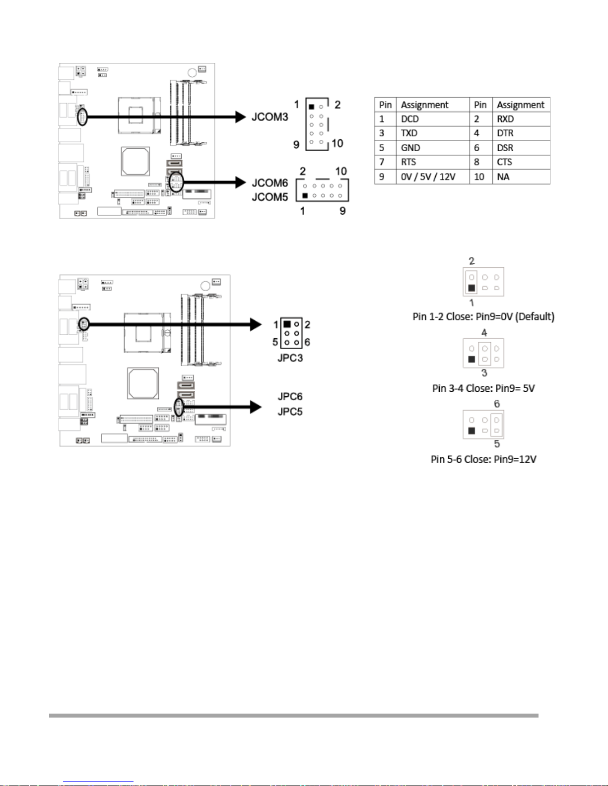
JCOM3/JCOM5/JCOM6: Serial Port Headers
(The board h as built-in COM3 , no JCOM3 Connector))
JPC3/JPC5/JPC6: Serial Port Voltage Swi t ch Jumpers for JCOM3/JCOM5/JCOM6
66
Page 68
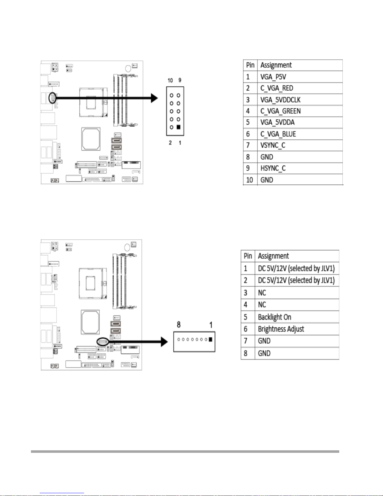
JVGA1: VGA Connect or (O ptional)
This header allows you to connect VGA
JC1: LCD Backlight Inverter Connector
This connector is for connecting to LCD for providing backlight control function. It is strongly
recommended to use the mat ching JOY DAY INDUSTRIAL - A1250WV-S-8P connector.
67
Page 69
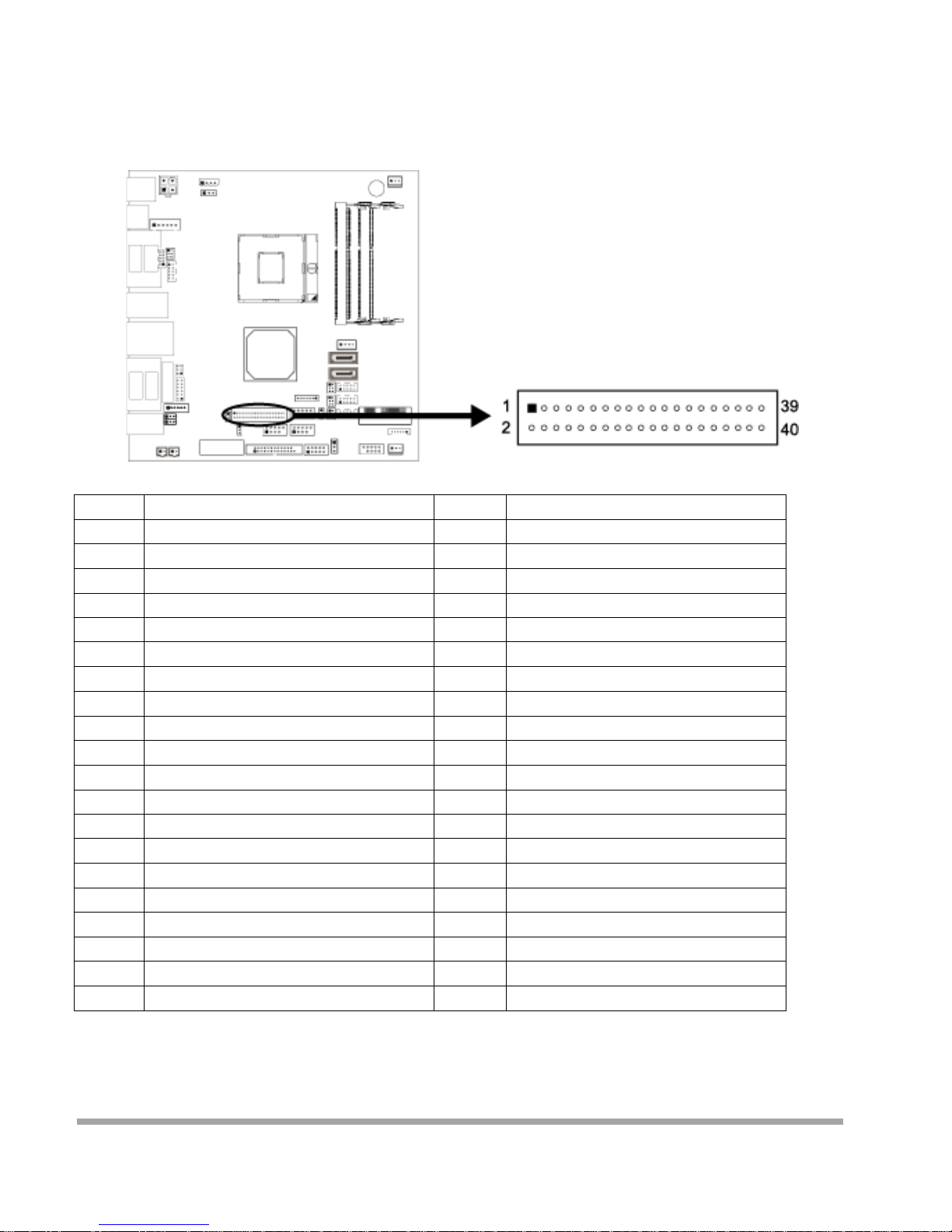
LVDS-O UT1: LVDS Connector
This connector supports 18/24 bit si ngle -channel panels.
»» I t is strongly re commended to use t he matching JOY DAY INDUSTRIAL - A1252WV-SF-2X20PD01
connector.
Pin Assignment Pin Assignment
1 LVDSB_DATA0_N 2 PVDD2, 3.3V/5V (selected by JLV2)
3 LVDSB_DATA0_P 4 PVDD2, 3.3V/5V (selected by JLV2)
5 GND 6 GND
7 LVDSB_DATA1_N 8 GND
9 LVDSB_DATA1_P 10 LVDSA_DATA0_N
11 GND 12 LVDSA_DATA0_P
13 LVDSB_DATA2_N 14 GND
15 LVDSB_DATA2_P 16 LVDSA_DATA1_N
17 GND 18 LVDSA_DATA1_P
19 LVDSB_CLK_N 20 GND
21 LVDSB_CLK_P 22 LVDSA_DATA2_N
23 GND 24 LVDSA_DATA2_P
25 LVDSB_DATA3_N 26 GND
27 LVDSB_DATA3_P 28 LVDSA_CLK_N
29 +5V 30 LVDSA_CLK_P
31 LVDSA_DDC-CLK 32 GND
33 +3.3V 34 LVDSA_DATA3_N
35 NC 36 LVDSA_DATA3_P
37 PVDD2, 3.3V/5V (selected by JLV2) 38 NC
39 PVDD2, 3.3V/5V (selected by JLV2) 40 LVDSA_DDC_DATA
68
Page 70
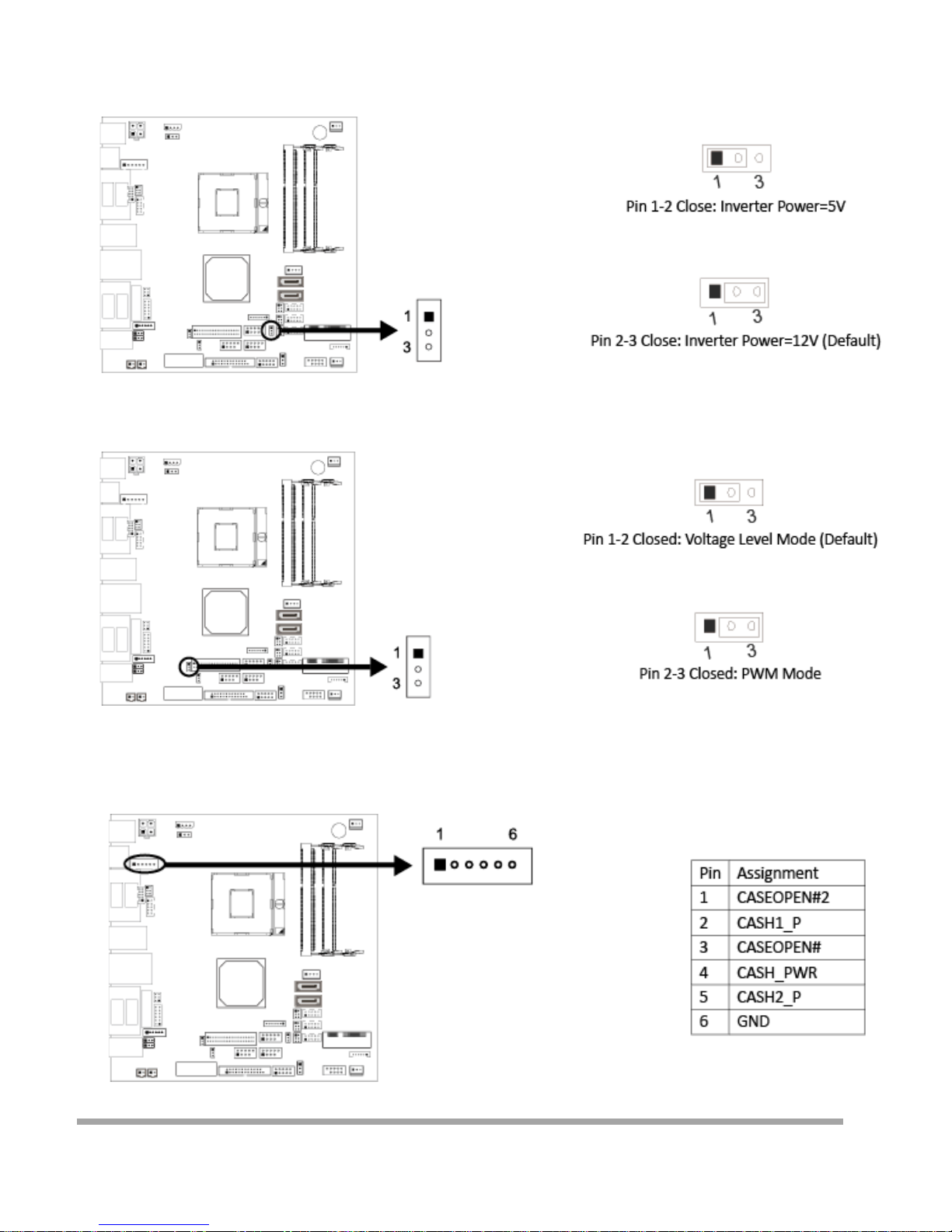
JLV1: LCD Backlight Inverter Power Select Ju mper
This jumper is fo r selecti ng LCD Backlight Inverter Power
JLV2: LCD Panel Pow er Select Jumper
This jumper is for selecting LCD Pow e r(PVDD2).
JRJ11: Cash Draw Heade r
This onboar d header is for cash drawer function, but when it is in use, you can not use the I/O
RJ11 connector.
69
Page 71
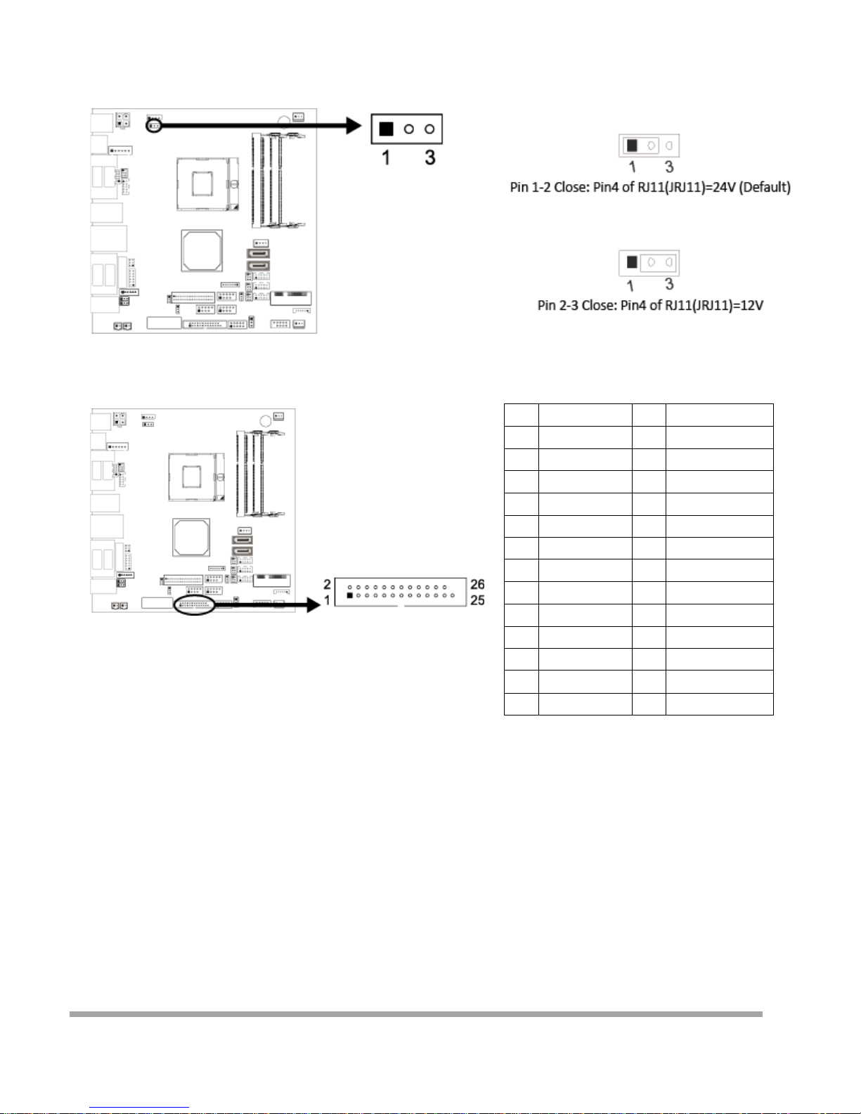
JP2: Voltage Swi t ch Header for Cash D raw Connect or
This header is for controlling the Pin4 of RJ11 ( JRJ11) t o switch 12V or 24V.
JPRNT1: Print er Port Connector
This header allows you to connect printer port on t he PC.
JDIO1: Digital I/O Connector
This connector offers 4-pair of digital I/O functions and address is set in BIOS.
Pin Assignment Pin Assignment
1 Strobe 2 ALF
3 Data 0 4 -Error
5 Data 1 6 -Init
7 Data 2 8 -Scltin
9 Data 3 10 Ground
11 Dat a 4 12 Ground
13 Dat a 5 14 Ground
15 Dat a 6 16 Ground
17 Dat a 7 18 Ground
19 -ACK 20 Ground
21 Busy 22 Ground
23 PE 24 Ground
25 SCLT 26 Key
70
Page 72
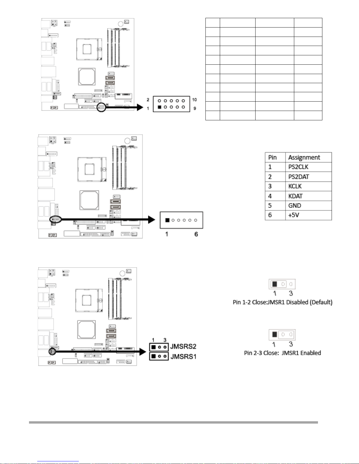
JMSR1: MSR Connector
The mainboard provides MSR connector.
JMSRS1/JMSRS2: MS R Ju mpe r
The jumpers enable or disable MSR connector function.
Pin Assignment Address GPIO
1 5V
2 DI-01 548H BIT7 GPIO71
3 DO-01 50CH BIT7 GPIO7
4 DI-02 548H BIT6 GPIO70
5 DO-02 50CH BIT6 GPIO6
6 DI-03 548H BIT5 GPIO69
7 DO-03 50CH BIT1 GPIO1
8 DI-04 548H BIT4 GPIO68
9 DO-04 50CH BIT17 GPIO17
10 GND
71
Page 73
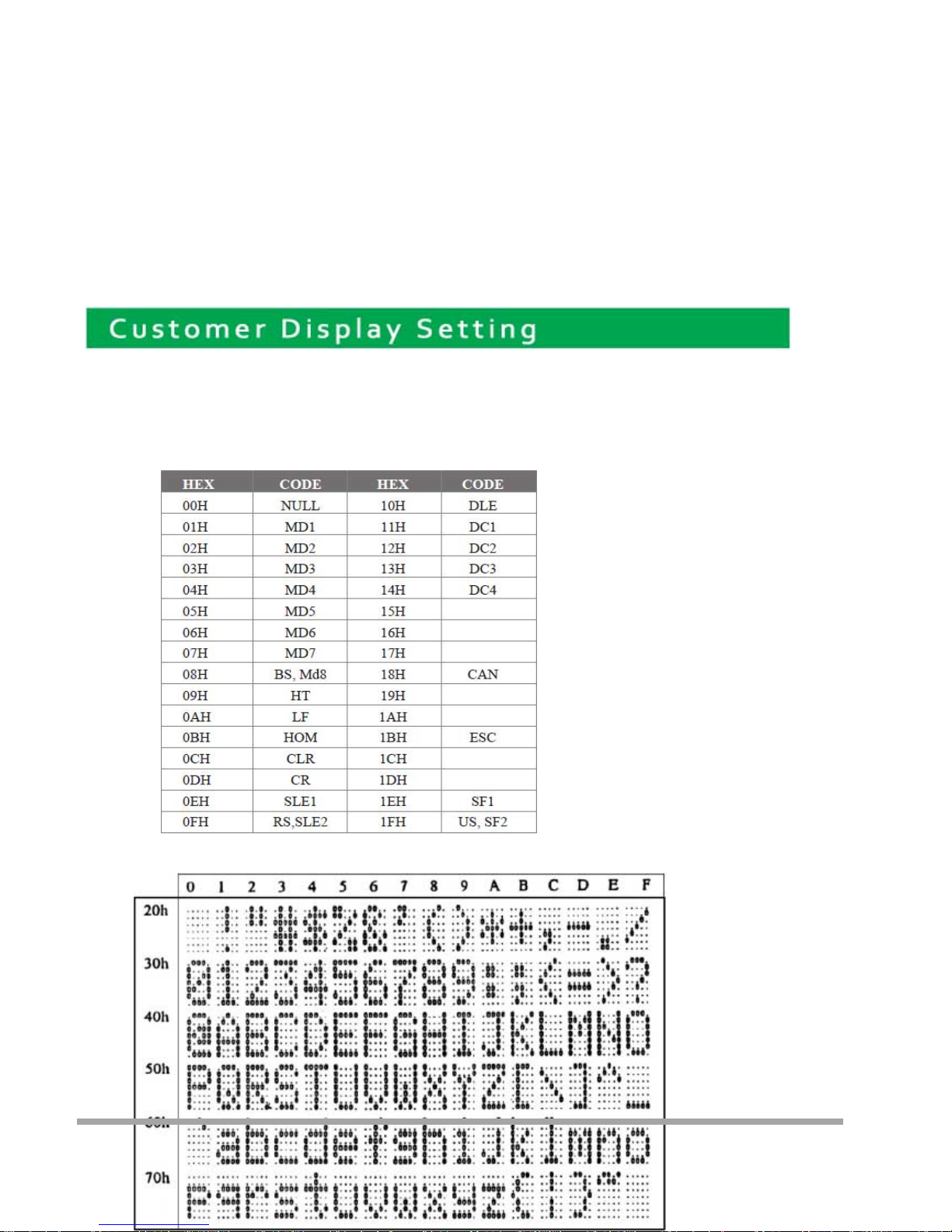
Character Font Table
A. Control code set
B. U.S.A. font set
7
72
Page 74
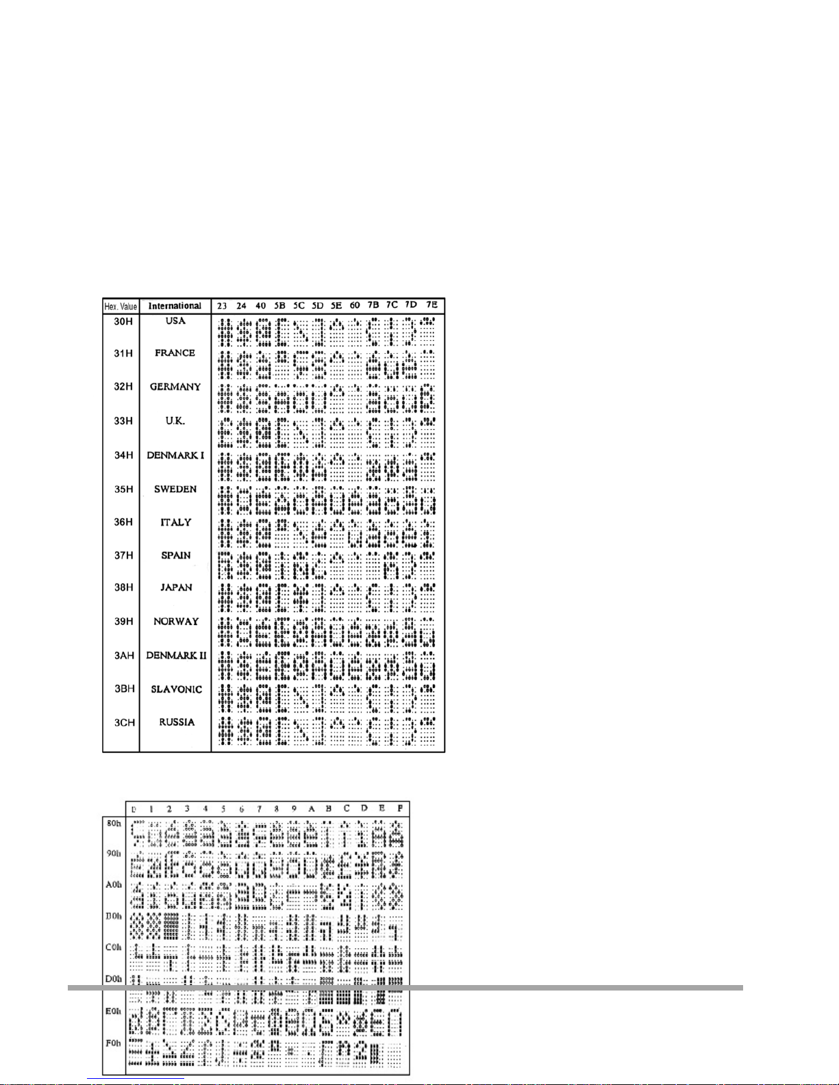
C. International character selection
ASCII CODE
3DH: Standa rd Europe international font set
73
Page 75
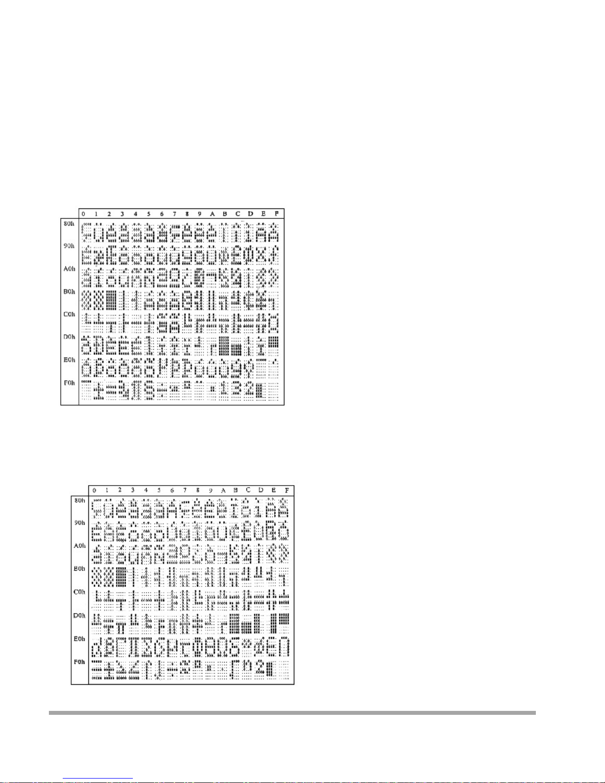
3EH: Multingual international fo nt set
3FH: Portuguese international font set
74
Page 76
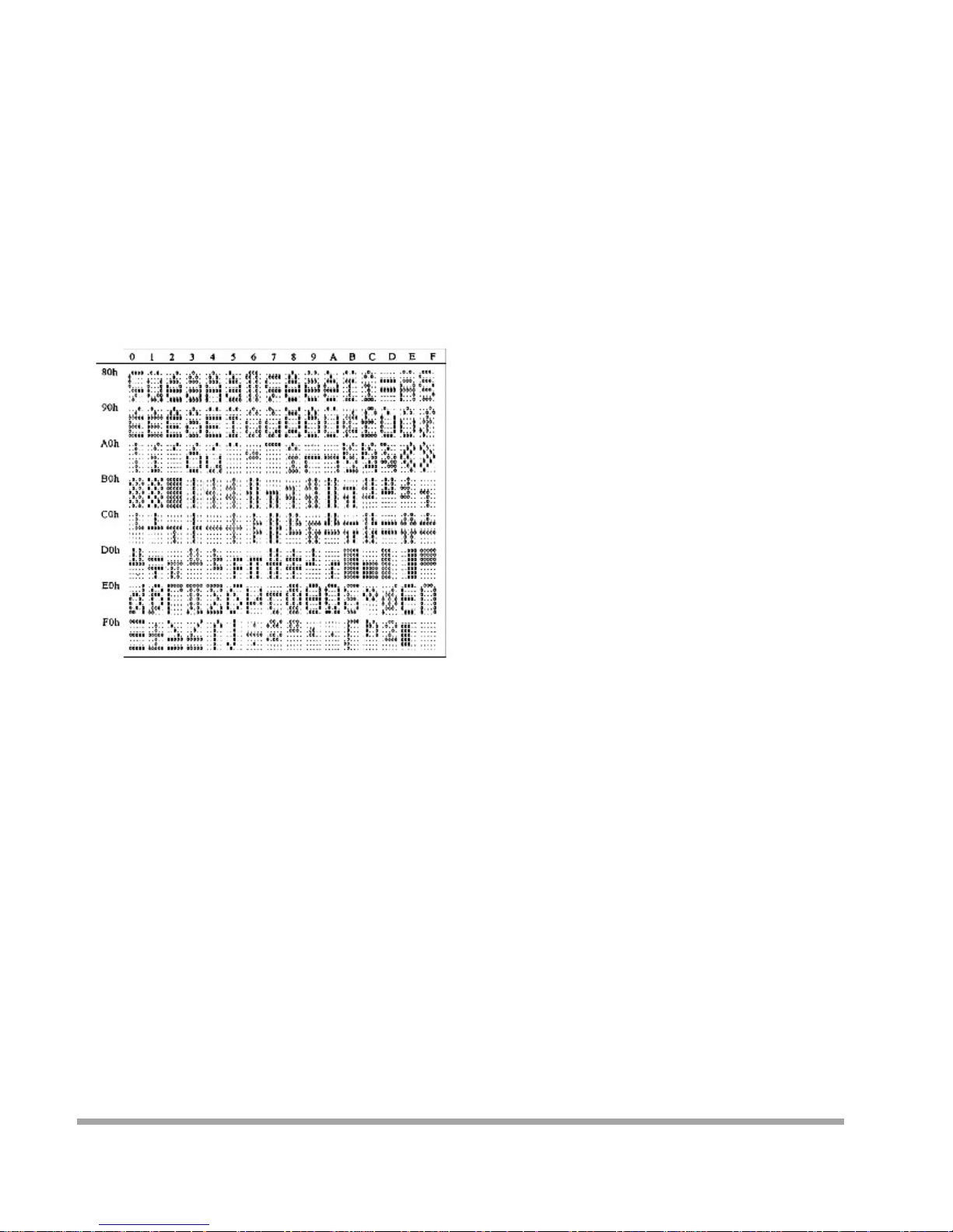
40H: Canadian French internatio nal fo nt set
41H: NORDIC int er nat ional font set
75
Page 77
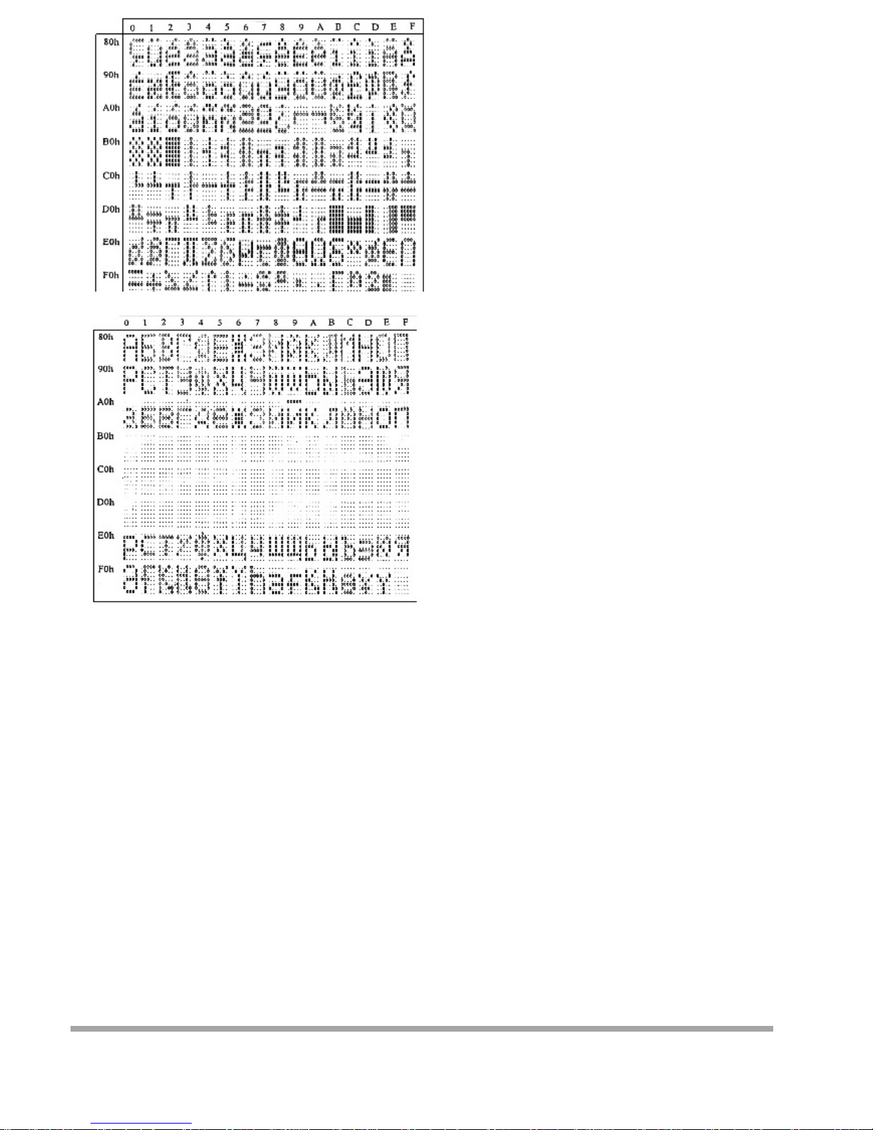
42H: RUSSI A font set
43H: SLAVONIC Font s et
76
Page 78
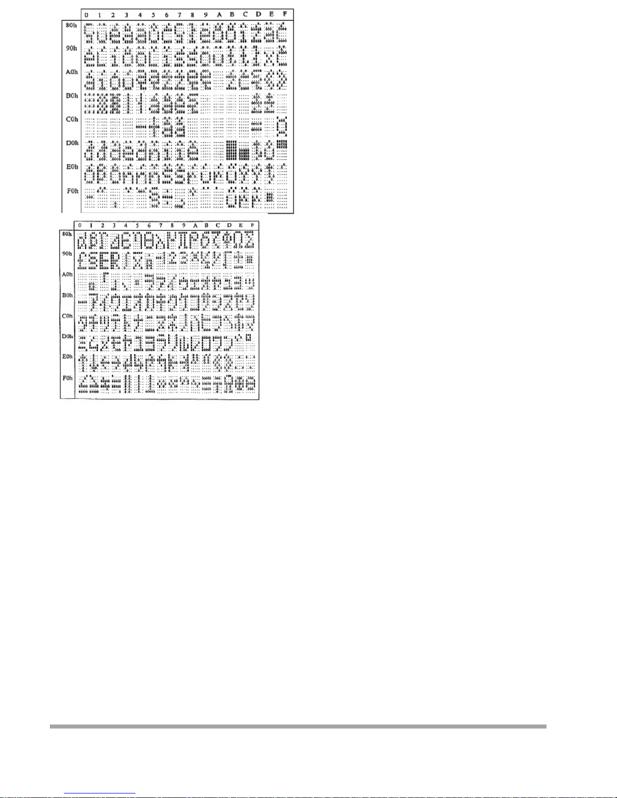
44H: Katakana font set
77
Page 79
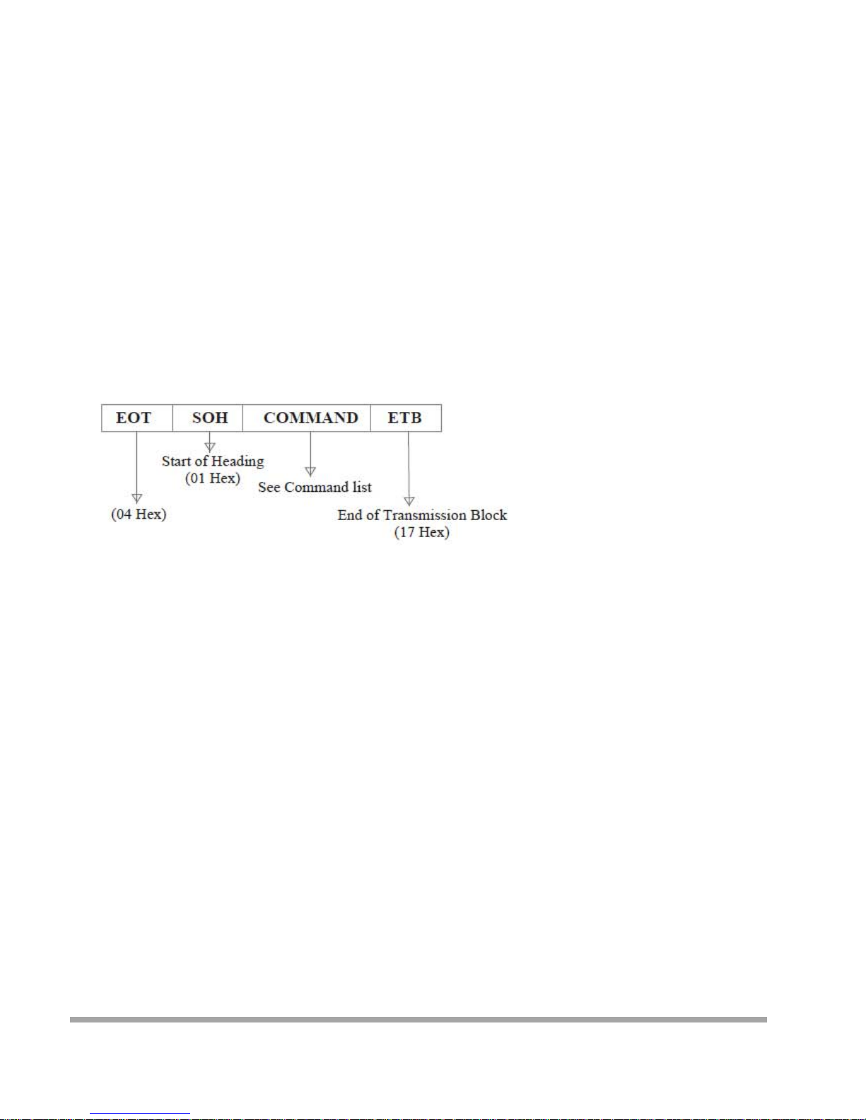
System Commands
Command Format
Command List
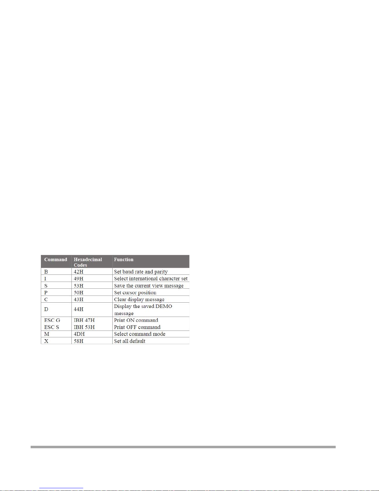
A. Set Baud Ra te
COMMAND: B
COMPUTER:EOT SOH 'B' 'BAUD RATE' 'N' ETB
ASCII (04H) (01H)(42H) (31H~37H)(4EH)(17H)
Byte 1 1 1 1 1 1
DISPLAY: ACK (or NACK if failed)
ASCII (06H) (15H)
Byte 1 1
Note: Baud rates
31H: 9600
32H: 4800
33H: 2400
34H: 1200
35H: 600
36H: 300
37H:19200
78
Page 80
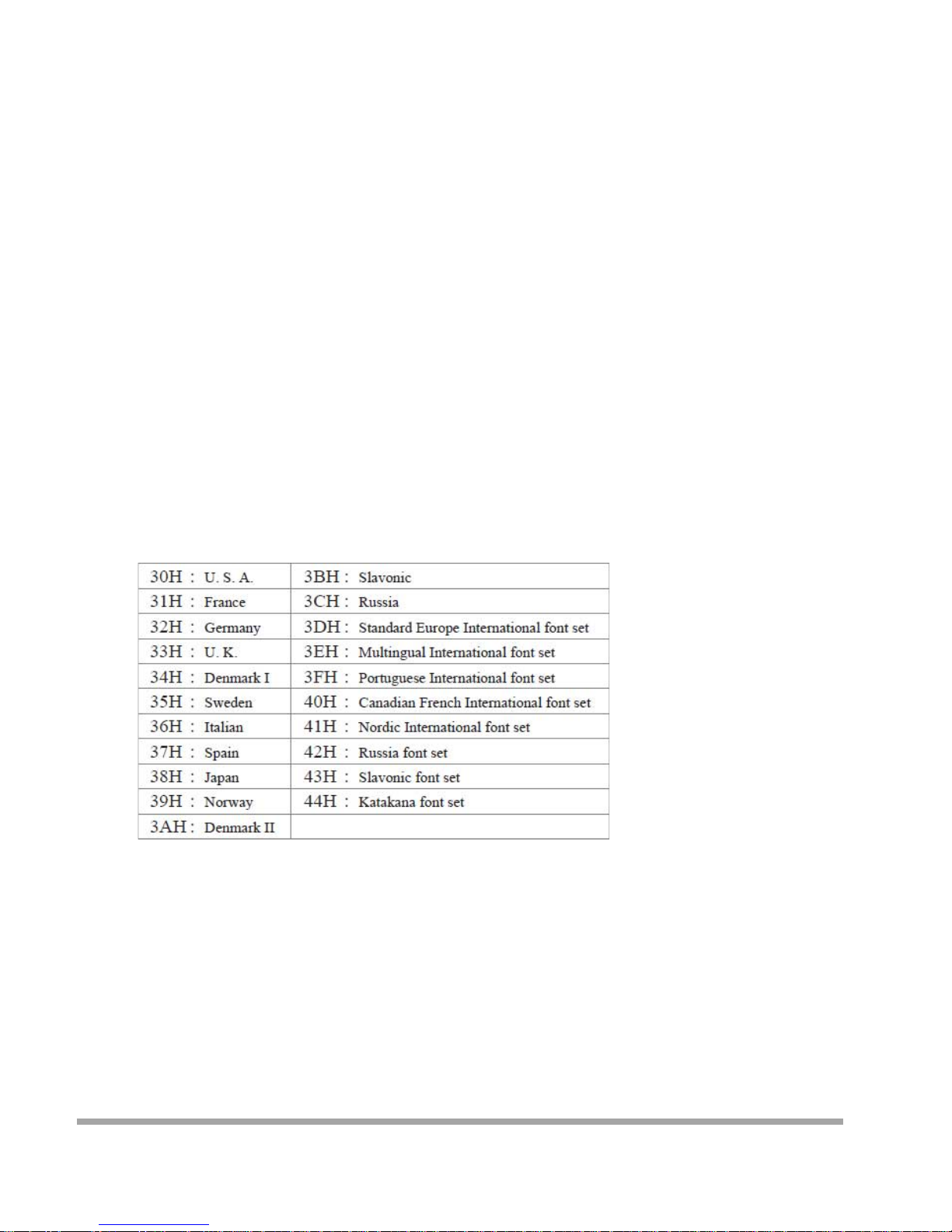
B. Select international code table
COMMAND: I
COMPUTER:EOT SOH 'I ' 'CHAR' ETB
ASCII(04H)(01H)(49H)(30H~44H)(17H)
Byte 1 1 1 1 1
DISPLAY: ACK (or NACK if failed)
ASCII (06H) (15H)
Byte 1 1
Note : International Character Code
C. Save the curren t vi ew message
(Sa ve Demo view dat a)
COMMAND: S
COMPUTER:EOT SOH 'S ' 'Layer' ETB
ASCII(04H)(01H)(53H)(31H~33H)(17H)
Byte 1 1 1 1 1
DISPLAY: ACK (or NACK if failed)
ASCII (06H) (15H)
Byte 1 1
79
Page 81

Note : 31H: Layer 1 / 32H: Layer 2 / 33H: Layer 3
D. Set cursor p ositi on
COMMAND: P
COMPUTER: EOT SOH 'P' 'Position' ETB
ASCII (04H) (0 1H) (50H) (31H~58H) (17H)
Byte 1 1 1 1 1
DISPLAY: ACK (or NACK if failed)
ASCII (06 H ) (15H)
Byte 1 1
Note: Th e cursor c an be set to the p osition from 1 to 40
Position 1 means the upper left corner position.
Position 20 means the upper right corner position.
Position 21 means the lower left corner position.
Position 40 means the lower right corner position.
E. Clear disp lay rang e
COMMAND: C
COMPUTER: EOT SOH 'C' 'START' 'END' ETB
ASCII (04H)(01H)(43H)(31H~58H)(31H~ 58H)(17H)
Byte 1 1 1 1 1
DISPLAY: ACK (or NACK if failed)
ASCII (06H) (15H)
Byte 1 1
Note: Some part of the cu r rent view messages can be
cleared by this COMMAND. It can start clearing
between position 1 and position 40.
F. Display the saved DEMO message
COMMAND: D
COMPUTER: EOT SOH 'D' 'Layer' 'Mode' ETB
ASCII (04H)(01H)(44H)(31H~37H)(31H~ 33H)(17H)
Byte 1 1 1 1 1
DISPLAY: ACK (or NACK if failed)
ASCII (06H) (15H)
Byte 1 1
Note:
a) There are three layers of saved view messages as described on COMMAND "S "
b) There are two modes of display:
Mode 1 is running the saved messages from right to left, which is a horizontal scroll mode.
80
Page 82
Mode 2 is running the saved messages from the lower line to the upper line, which is a vertical scroll mode.
c) For display layers:
select 31H means display the message saved on layer 1.
select 32H means display the message saved on layer 2.
select 33H means display the message saved on layer 1+ layer2.
select 34H means display the message saved on layer 3.
select 35H means display the two messages saved on layer 1 + layer 3.
select 36H means display the two messages saved on layer 2 +layer 3.
select 37H means display all the messages saved on layer 1 +layer 2 + layer 3.
d) For display modes,
select 31H means display the message with Mode 1.
select 32H means display the message with Mode 2.
select 33H means display the message with Mode 1+Mode 2.
For this Demo display function, you must have saved the message by COMMAND "S" previously, For example,
select 37H for displaying layers and select 33H for displaying modes, DSP would display all the three messages saved on
layer 1+ layer 2 + layer 3 with both Mode 1 + Mode 2 displaying modes.
e) Any new message from the computer would stop this Demo
display function and DSP would display that new message from the computer.
G. Select the Command Mode
COMMAND: M
COMPUTER: EOT SOH 'M' 'Mode' ETB
ASCII (04H) (01H) (4DH)(30H~38H) (17H)
Byte 1 1 1 1 1
DISPLAY: ACK (or NACK if failed)
ASCII (06H) (15H)
Byte 1 1
Note: Command Modes Selection
H. Set all default
COMMAND: X
COMPUTER: EOT SOH 'X' ETB
ASCII (04H) (0 1H) (58H) (17H)
Byte 1 1 1 1
81
Page 83

Transmission method
Each ASCII character is transmitted with
1 start bit
8 data bits
1 stop bit
No parity
Note: You may generate your own application software to run the display according to the standard
RS-232C communication protocols and the SOFTWARE CONTROL information listed on this chapter.
82
Page 84
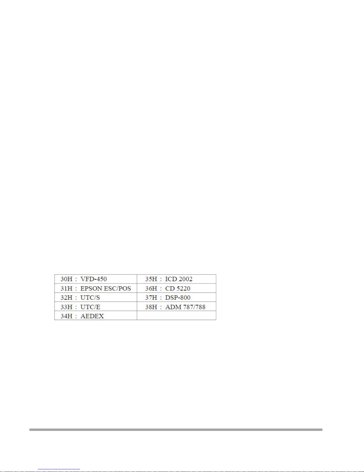
Command Modes
The c ommand modes can be selected with the Demo Software.
Mode 0: Default
Mode 1: EPSON Esc/POS
Mode 2: UTC S tandard
Mode 3: UTC E nhanced
Mode 4: AEDEX
Mode 5: ICD 2002
Mode 6: CD 5220
Mode 7: DSP -800
Mode 8: ADM 787/788
Mode 0: Default
83
Page 85
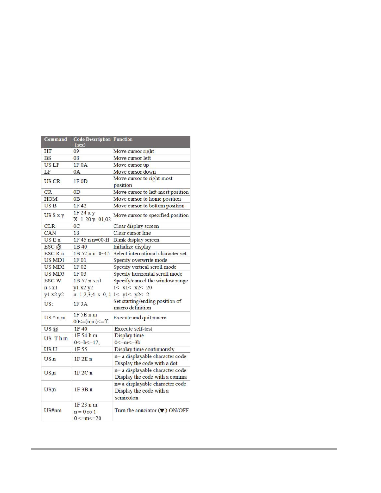
Mode 1 : EPSO N Es c /POS mode
Mode 2: UTC Standard mode
84
Page 86
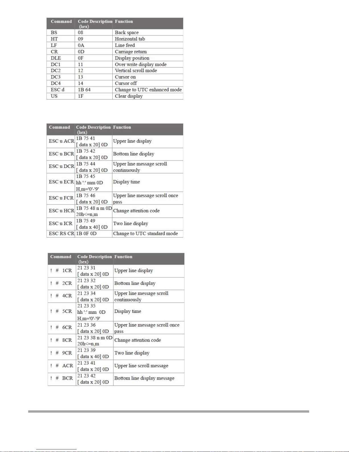
Mode 3: UTC enha nced mod e
Mode 4: AEDEX mode
85
Page 87
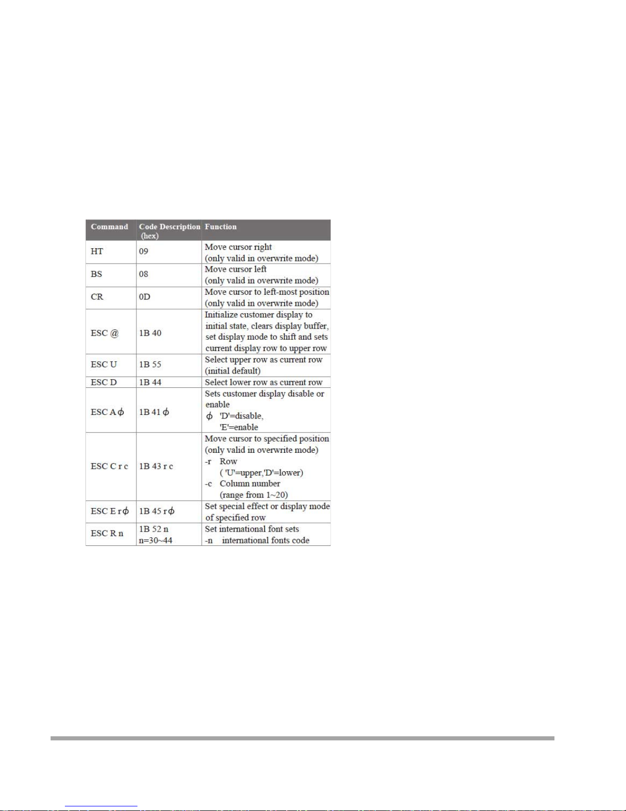
Mode 5: ICD 2002 mode
REMARK)* Using command "ESC E r Φ", the value of parameter:
r 58= all rows
55= upper row
44= lower row
86
Page 88
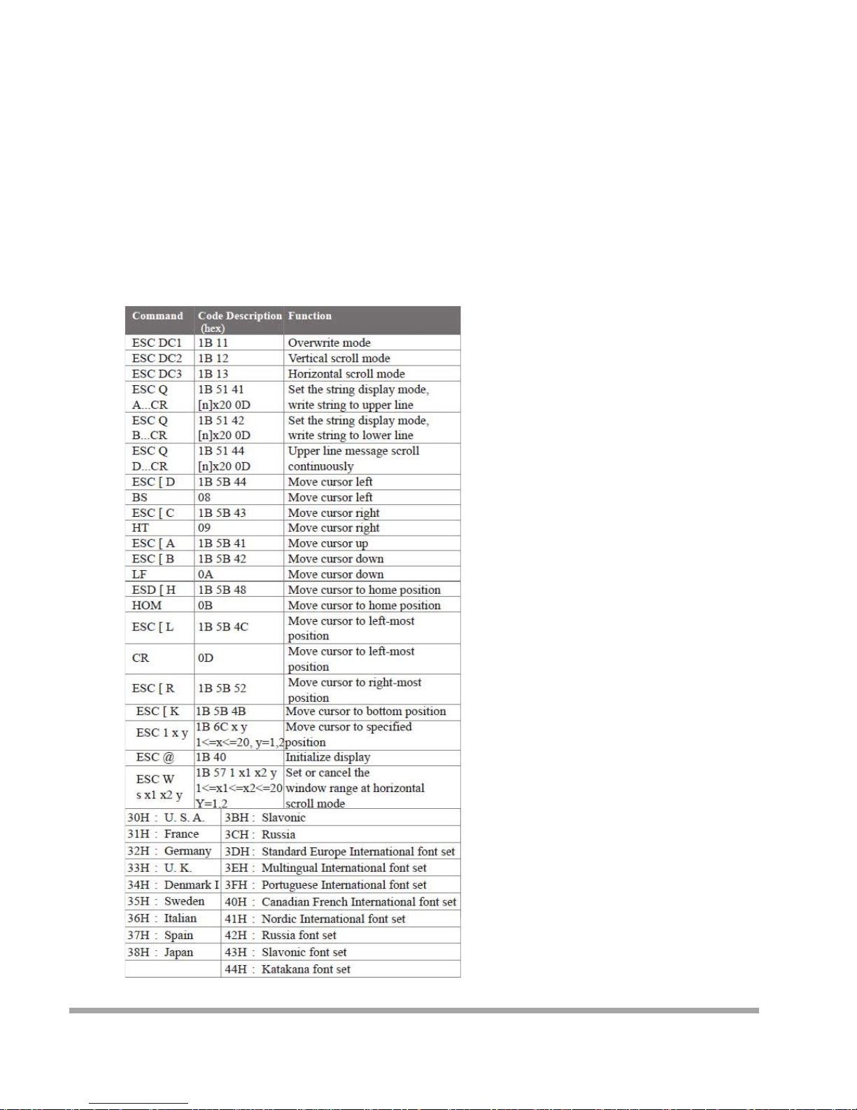
Φspeci al fun c tion , th e valu e is on e of
30= shift mode (default)
31= r otation mode
32= blink mode
33= clear this row and switch to shift mode
34= overwrite mode
35= vertical mode
Mode 6: CD 5220 standar d mod e
87
Page 89
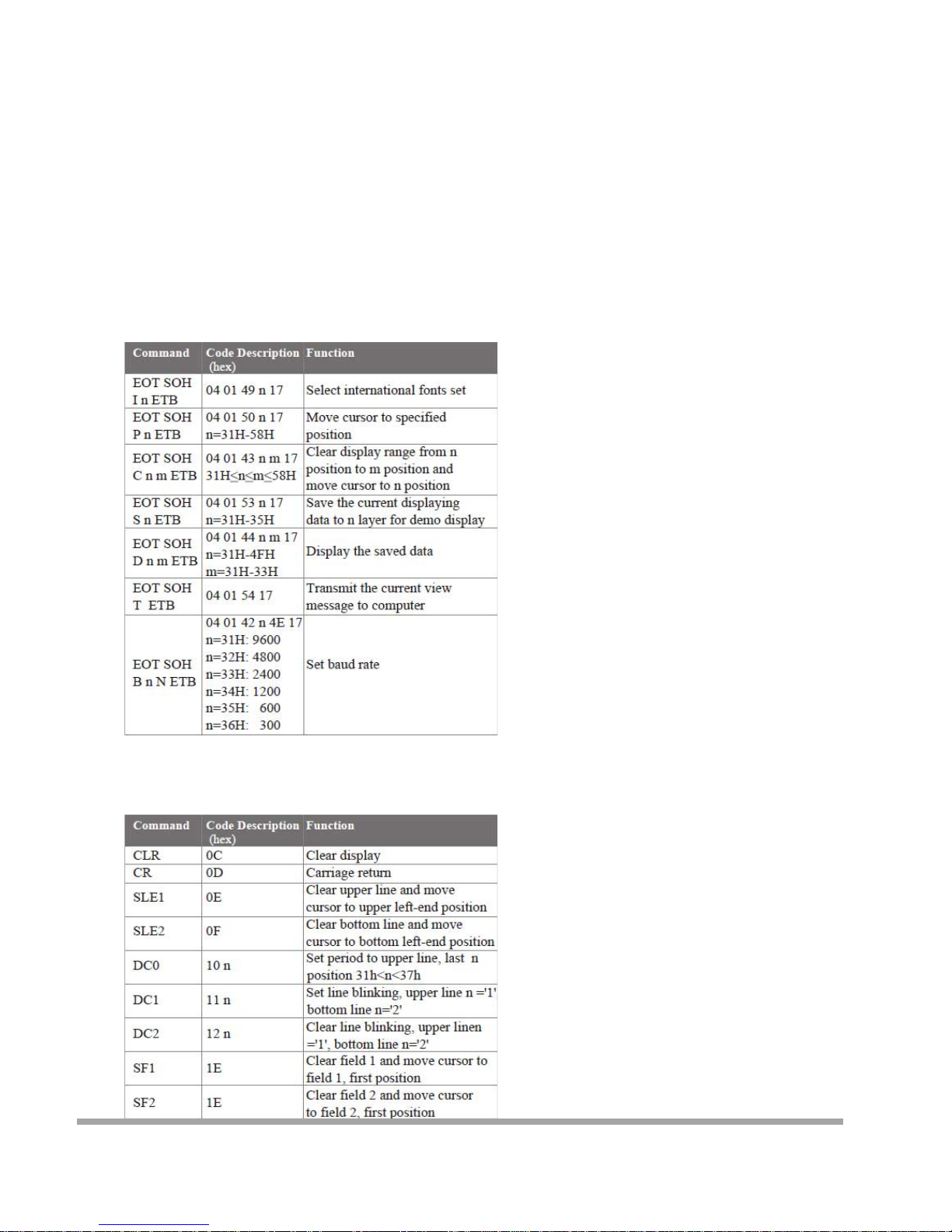
Mode 7: DSP-800 mode
Mode 8: ADM 787/788 mode
88
Page 90

CE MARK
This device compiles with the requirements of the EEC directive 89/336/EEC with regard to
“Electromagnetic compatibility” and 73/23/EEC “Low Voltage Directive”
FCC This device complies with part 15 of the FCC rules. Operation is subject to the following two
conditions:
(1)This device may not cause harmful interference.
(2)This device must accept any interference received, including interference that may cause
undesired operation.
CAUTION ON LITHIUM BATTERIES
There is adapter of explosion if the battery is replaced incorrectly. Replace only with the same or equivalent type
recommended by the manufacturer. Discard used batteries according to the manufacturer’s instructions.
LEGISLATION AND WEEE SYMBOL
2002/96/EC Waste Electrical and Electronic Equipment Directive on the treatment, collection,
recycling and disposal of electric and electronic devices and their components.
The crossed dustbin symbol on the device means that it should not be disposed of with other
household wastes at the end of its working life. Instead, the device should be taken to the
waste collection centers for activation of the treatment, collection, recycling and disposal
procedure.
To prevent possible harm to the environment or human health from uncontrolled waste disposal,
please separate this from other types of wastes and recycle it responsibly to promote the sustainable reuse of
material resources.
89
Page 91

Household users should contact either the retailer where they purchased this product, or their local government
office, for details of where and how they can take this item for environmentally safe recycling.
Business users should contact their supplier and check the terms and conditions of the purchase contract.
This product should not be mixed with other commercial wastes for disposal.
90
 Loading...