

Czaki EMT-200 Operating Manual

ul. 19 Kwietnia 58
05-090 Raszyn Rybie
tel. (+48 22) 720 23 02
fax. (+48 22) 720 23 05
www.czaki.pl
handlowy@czaki.pl
MICROPROCESSOR CONTROLLED TEMPERATURE METER
EMT-200
OPERATING MANUAL

Contents
1. Meter features ..............................................................3
2. Display and keyboard...................................................4
2.1. Description of display functions ..............................5
2.2. Using keyboard.......................................................5
3. Programming mode......................................................6
4. Menu AL_1 or AL_2..................................................... 8
4.1. Setting the alarm mode.......................................... 8
4.2. Setting alarm thresholds.........................................9
5. MEMO menu................................................................ 9
5.1. Cyclic readout period..............................................9
5.2. Printing results......................................................10
5.3 Recording results...................................................10
6. SYST menu................................................................ 11
6.1. Protection.............................................................11
6.2. Reset.....................................................................11
7. TEPR menu................................................................12
7.1 Sensor type............................................................12
7.2. Resolution of measurements................................12
7.3. Characteristic offset..............................................13
8. R232 menu.................................................................13
8.1. Meter address.......................................................14
8.2. Transmission rate................................................. 14
8.3. Parity check.......................................................... 15
9. Programming the meter through the RS232 port....... 15
9.1. Data format...........................................................15
9.2. Parameter symbols...............................................16
10. Making electrical connections.................................. 17
10.1. Power supply...................................................... 17
10.2. Sensor................................................................ 18
10.3. Alarm circuits...................................................... 18
10.4. Serial port........................................................... 19
11. Remarks concerning operational use of the meter...19
12. Technical data.......................................................... 20

1. Meter features
The EMT 200 is an universal microprocessor controlled temperature
meter. Its main features are:
! input adjusted to most commonly used types of thermocouples and
thermistors
! two alarms controlling independent relays, programmable in five
modes
! bi-directional RS232 serial port, isolated, making possible remote
readout and storage of the most important parameters
! memory of 300 measurements
! meter parameters and configuration set through a keyboard or
serial port
! two four digit LED displays and three additional status lights
3
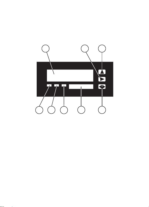
2. Display and keyboard
Double display and three key keyboard are placed on the front panel
of the meter. The panel is presented in the picture below:
1
7
6
4
3
5
1 Main display
2 Auxiliary display
3 „ALARM 1” LED
4 „ALARM 2” LED
5 „TRANSMISSION” LED
6 „p” key
7 „u” key
8 „tu” key
2
4
8

2.1.Description of display functions
Switching on the meter results in displaying the „LOAD” message on
the main display. It means starting the meter.
In the basic mode the display presents temperature in
degrees Centigrade. The unit of measurements is shown on the
auxiliary display..
In the programming mode the main display shows
consecutive positions of menu or parameter names, and the
auxiliary display presents their respective values..
If the LED „ALARM 1” or / and „ALARM 2” comes on it
means that the measured temperature has entered the
programmed alarm range.
While modifying (meter) parameters the value indicated in
the active field of the auxiliary display is also changed. The
active field is distinguished by blinking of selected position.
If the main display shows the „ERR” message it means that
the processing range has been exceeded, a sensor has been
incorrectly connected, or the sensor previously programmed
differs from the sensor actually connected.
2.2.Using keyboard
The meter is equipped with the three key membrane keyboard..
The key „p” is used for changing the value of the active
(blinking) digit. It is also intended for entering the parameter
programming mode and for leaving this mode.
The key „u” makes possible changing the menu position
and changing the active digit.
The key „tu” is intended for confirming the selected menu
position, or for confirming the (selected) value.
5

3.Programming mode
The programming mode is entered by pressing „p” for approx. 3
seconds.
It results in the message „AL_1” appearing on the main display.
Repetitive depressing of „u” scrolls consecutive menu positions.
Finding the appropriate menu position is confirmed by pressing
„tu”.
Depressing „p” causes entering the higher menu level. The same at
the highest menu level results in leaving the programming mode and
entering the temperature measurement mode.
If the user does not change any parameters the programming mode
will go off automatically after approx. 90 seconds.
At the parameter change procedure the key „p” changes the value
under the cursor, and the key „u” shifts the cursor position (if possible).
Changing parametr value:
Using „u” activate the digit to be changed on the auxiliary display ;
Using „p” set the new value;
Repeat this procedure till the required value is set completely;
Introduced changes confirm by „tu”. It causes memorizing the
parameter value.
ATTENTION: If the entered value exceeds premissible limits then on
the auxiliary display the „ERR” message appears for a while, after that
the previous value (before modification) is continously displayed.
6

Displayed
AL_1
AL_2
MEMO
SYST
TEPR
R232
symbol
RSCT
TPRI
TMEM
PROT
RESE
SNSR
TPOI
TOFF
BAUD
PARI
TAL
P1
P2
TAL
P1
P2
ADR
Admissible values
0, 1, 2, 3, 4, 5
-100...+1800
-100...+1800
0, 1, 2, 3, 4, 5
-100...+1800
-100...+1800
1...240
0, 1, 2
0, 1, 2
0, 1, 2
0, 1
Pt,Ni,T,J,K,R,S,B,N
0, 1
-9.9...+9,9
1...99
600,1200,2400
4800,9600
NONE, ODD, EVEN
Factory
settings
0
2
10
0
4
100
10
0
0
0
0
K
0
0.0
1
2400
NONE
Parameter description
alarm mode 1
item 1
item 2
alarm mode 2
item 1
item 2
readout period
results readout
results recording
protection
reset
sensor type
resolution
offset
address
rate
parity
ATTENTION: Parameters in the shaded fields are accessible if the
„p” key has been depressed at the moment of switching
on the meter.
7

4.Menu AL_1 or AL_2
Programming alarms consists in setting their work modes and values
of threshold temperatures.
Enter the programming mode by depressing „p” for approx. three
seconds.
Using „u” select from the menu position „AL_1” or „AL_2”, confirm
by „tu”.
4.1. Setting the alarm mode
In the alarm programming mode using „u” select „TAL ” position.
The auxiliary display will show the current alarm mode. To change
the mode depress „tu” (the digit on the auxiliary display starts
blinking).
Using „p” set the required alarm mode.
! Mode 0 alarm is off,
! Mode 1 alarm comes on when the current temperature exceeds the
first alarm threshold,
! Mode 2 alarm comes on when the current temperature drops below
the first alarm threshold,
! Mode 3 alarm comes on when the current temperature exceeds the
first alarm threshold, and at the same time is lower than the second
alarm threshold.
! Mode 4 alarm comes on when the current temperature drops below
the first alarm threshold or exceeds the second alarm threshold.
! Mode 5 alarm comes on when the current temperature exceeds the
second alarm threshold, and comes off when temperature drops below
the first alarm threshold (hysteresis). If a power outage appears in this
mode the meter memorises states of relays and the last temperature,
This makes possible correct alarm operation after re-powering.
Alarm modes are presented in a graphical form on page 22.
8
 Loading...