

Cytron Technologies Smart Series, MDDS10, SmartDriveDuo-10 User Manual
ROBOT . HEAD to TOE
Product User’s Manual – MDDS10
SmartDriveDuo-10
MDDS10
User's Manual
V1.0
June 2015
Created by Cytron Technologies Sdn. Bhd. – All Rights Reserved 1

ROBOT . HEAD to TOE
Product User’s Manual – MDDS10
INDEX
1. Introduction 3
2. Packing List 4
3. Product Specifications 5
4. Board Layout 6
5. Power Supply 9
6. Motor Connection 10
7. Safety Features 11
8. Input Modes 12
a. RC Input Mode 14
b. Analog/PWM Input Mode 16
c. Simplified Serial Mode 18
d. Packetized Serial Mode 20
9. Warranty 22
Created by Cytron Technologies Sdn. Bhd. – All Rights Reserved 2

ROBOT . HEAD to TOE
Product User’s Manual – MDDS10
1. INTRODUCTION
SmartDriveDuo-10 is one of the latest smart series motor drivers designed to drive medium
power brushed DC motor with current capacity up to 30A peak (few seconds) and 10A
continuously. This driver is designed specially for controlling differential drive mobile robot
using RC controller. Nevertheless, MDDS10 also can be controlled using analog joystick or
microcontroller (PWM, Serial). MOSFETs are switched at 16 KHz to ensure quiet operation
and no annoying whining sound. Besides, it also equipped with a microcontroller unit to
provide smart features such as multiple input mode and thermal protection.
SmartDriveDuo-10’s feature makes driving a robot with differential drive a truly plug and
play experience.
Some of the features for SmartDriveDuo-10 are summarized as below:
● Bi-directional control for dual brushed DC motor.
● Support motor voltage from 7V to 35V.
● Maximum current up to 30A peak (few seconds), 10A continuously.
● 16 KHz switching frequency for quiet operation.
● Battery low voltage indicator.
● Battery over voltage indicator.
● Thermal protection.
● Multiple input modes: RC, Analog, PWM, Simplified Serial and Packetized Serial.
● On board push buttons for fast test and manual operation.
● No polarity protection for V motor.
Created by Cytron Technologies Sdn. Bhd. – All Rights Reserved 3
ROBOT . HEAD to TOE
Product User’s Manual – MDDS10
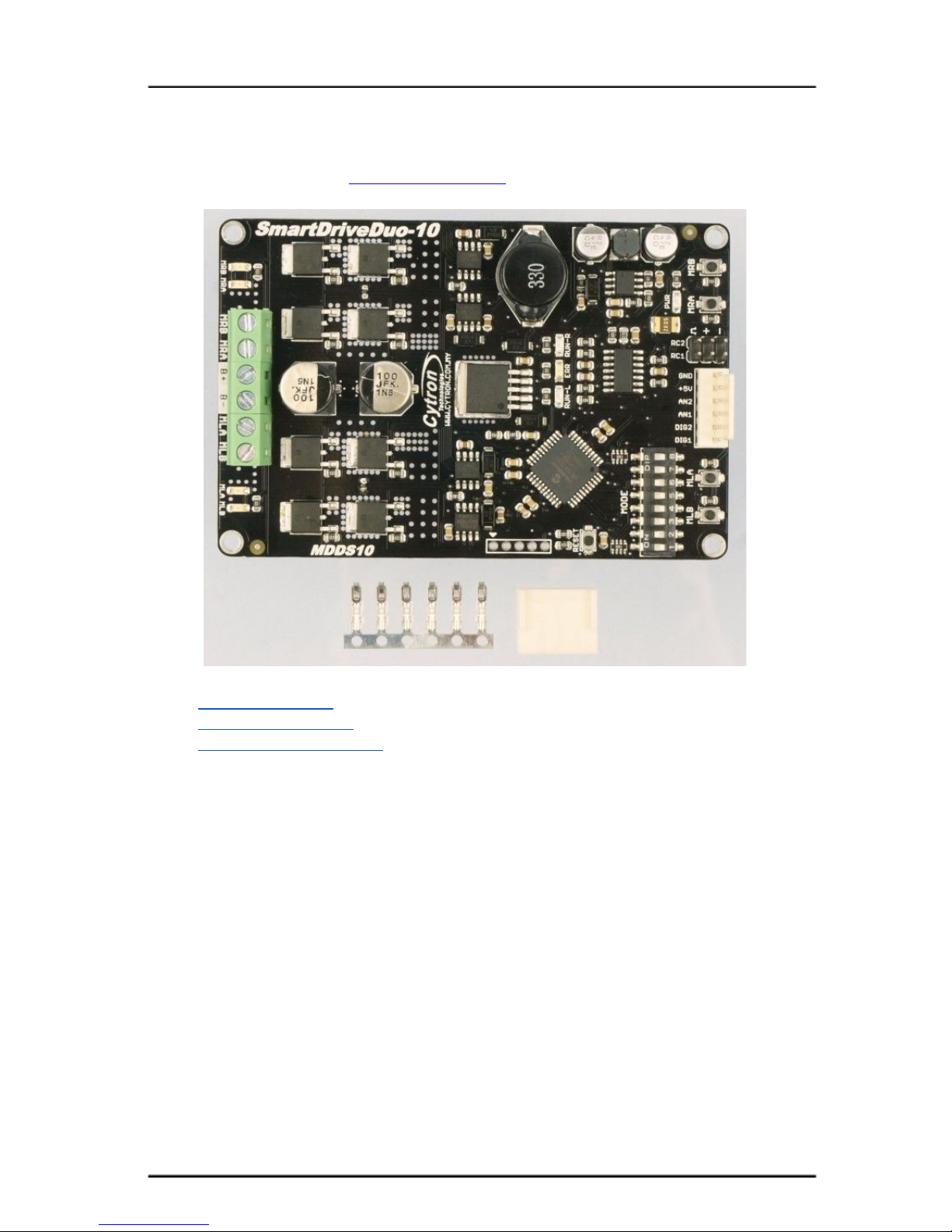
2. PACKING LIST
Please check the parts and components according to the packing list. If there are any parts
missing, please contact us at sales@cytron.com.my immediately.
● 1 x SmartDriveDuo-10
● 6 x Terminal pin for 2510
● 1 x 6-way Connector Housing
Created by Cytron Technologies Sdn. Bhd. – All Rights Reserved 4
ROBOT . HEAD to TOE
Product User’s Manual – MDDS10
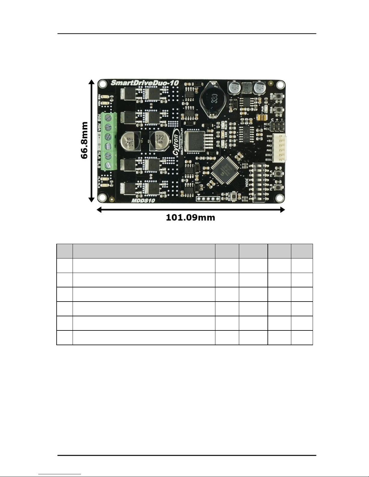
3. PRODUCT SPECIFICATIONS
Dimension:
Absolute Maximum Rating of SmartDriveDuo-10
No
Parameters
Min
Typical
Max
Unit
1
Input Voltage (Motor Supply Voltage)
7 - 35
V
2
I
MAX
(Maximum Continuous Motor Current)*
- - 10
A
3
I
PEAK
– (Peak Motor Current) **
- - 30
A
4
V
IOH
(Logic Input – High Level)
1.3 - 5
V
5
V
IOL
(Logic Input – Low Level)
0 - 0.7
V
6
5V Output Current
- - 500
mA
* Depends on the room temperature.
** Must not exceed 1 second.
Created by Cytron Technologies Sdn. Bhd. – All Rights Reserved 5
ROBOT . HEAD to TOE
Product User’s Manual – MDDS10
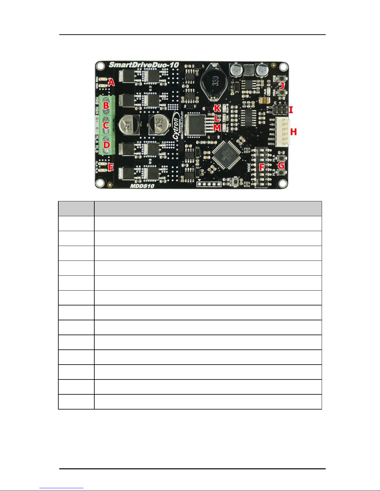
4. BOARD LAYOUT
Label
Function
A
Motor RIGHT LED Indicator
B
Motor RIGHT Terminal Block
C
Power Supply Terminal block
D
Motor LEFT Terminal Block
E
Motor LEFT LED Indicator
F
Mode Selection DIP Switch
G
Motor LEFT Test Button
H
Analog/PWM/Serial Input Pin
I
RC Input Pin
J
Motor RIGHT Test Button
K
Motor RIGHT Run LED
L
Error LED
M
Motor LEFT Run LED
Created by Cytron Technologies Sdn. Bhd. – All Rights Reserved 6
ROBOT . HEAD to TOE
Product User’s Manual – MDDS10
FUNCTION Description:
Motor RIGHT LED Indicator
Indication for current flow and direction for motor RIGHT. If LED MRA turns on, means
current flows from output MRA to MRB. Vice versa.
Motor RIGHT Terminal Block
Connect to motor RIGHT at your mobile robot. User can tie the wire to the terminal block or
solder the wire directly to the pad at bottom layer.
Power Supply Terminal Block
Connect to power source. User can tie the wire to the terminal block or solder the wire
directly to the pad at bottom layer. No polarity protection, please double check before
power up.
Motor LEFT Terminal Block
Connect to motor LEFT at your mobile robot. User can tie the wire to the terminal block or
solder the wire directly to the pad at bottom layer.
Motor LEFT LED Indicator
Indication for current flow and direction for motor LEFT. If LED MLA turns on, means
current flows from output MLA to MLB. Vice versa.
Mode Selection DIP Switch
User can select different input mode by setting the DIP switch.
Motor LEFT Test Button
Fast test to check driver functionality for motor LEFT. If MLA is pressed, current flows from
output MLA to MLB. Vice Versa.
Analog/PWM/Serial Input Pin
No
Pin Name
Description
1
DIG1*
1: Digital signal (Direction) for motor LEFT.
2: Serial Simplified, Serial Packetized.
2
DIG2
Digital signal (Direction) for motor RIGHT.
3
AN1
Analog/PWM signal for motor LEFT.
4
AN2
Analog/PWM signal for motor RIGHT.
5
+5V
+5V output. Do not connect to another 5V source.
6
GND
Ground.
*DIG1 can accept 2 types of input.
**Please refer to INPUT MODE section for more detail.
RC Input Pin
This pins specially for RC receiver input wire. RC1 for forward/reverse and RC2 for steering.
Created by Cytron Technologies Sdn. Bhd. – All Rights Reserved 7
 Loading...