

Page 1
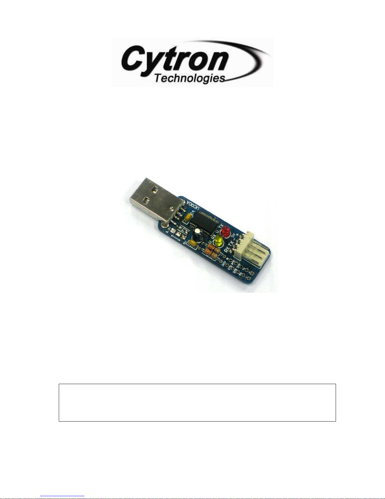
Cytron USB to UART Converter
UC00A
Information contained in this publication regarding device applications and the like is intended through suggestion only and may be
superseded by updates. It is your responsibility to ensure that your application meets with your specifications. No representation or warranty
is given and no liability is assumed by Cytron Technologies Incorporated with respect to the accuracy or use of such information or
infringement of patents or other intellectual property rights arising from such use or otherwise. Use of Cytron Technologies’s products as
critical components in life support systems is not authorized except with express written approval by Cytron Technologies. No licenses are
conveyed, implicitly or otherwise, under any intellectual property rights.
User’s Manual
V1.1
August 2009
Page 2
ROBOT . HEAD to TOE
Product User’s Manual – UC00A
Index
1. Introduction 1
2. System Overview 3
3. Packing List 4
4. Board Layout 5
5. Product Specification 6
6. Installation 9
a. Software Installation 9
b. Hardware Installation 9
7. Getting Started 10
7.1 Using UC00A with Microcontroller 10
7.2 Using UC00A for Communication between 2 PCs 15
8. Warranty 17
Created by Cytron Technologies Sdn. Bhd. – All Rights Reserved
Page 3
ROBOT . HEAD to TOE
1
Product User’s Manual – UC00A
1. INTRODUCTION
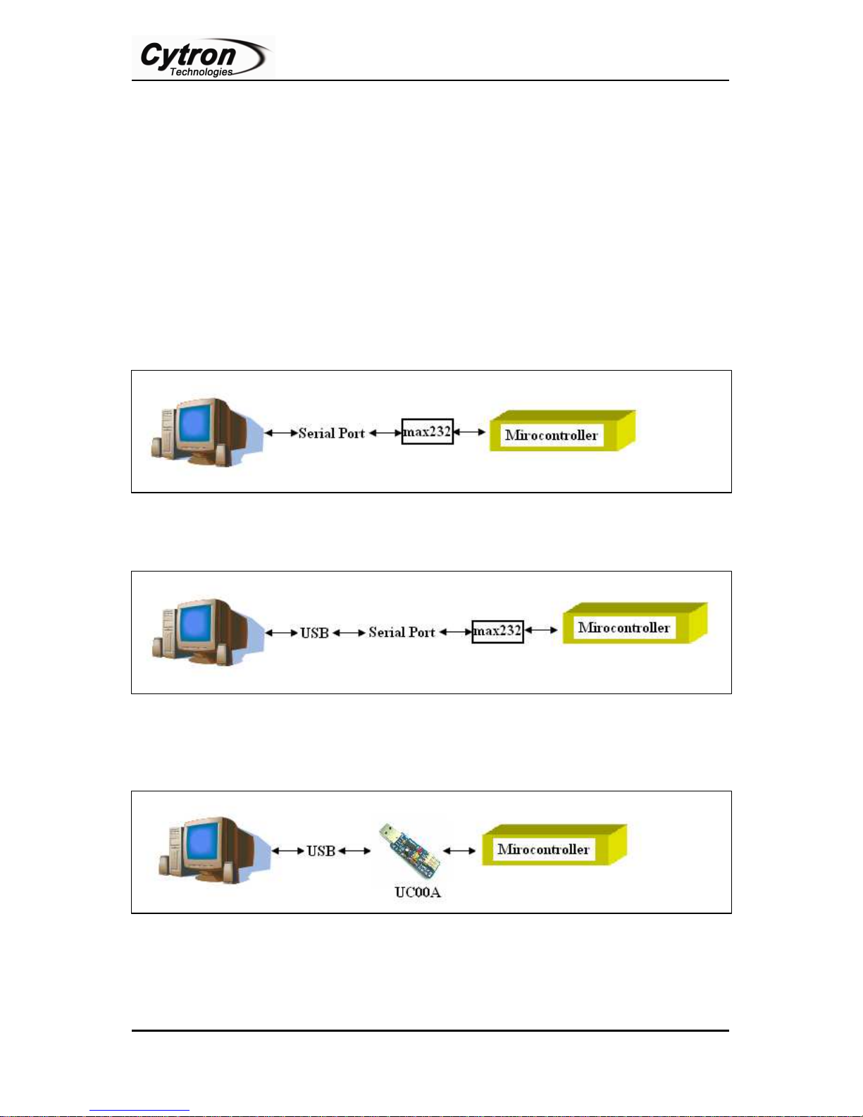
Serial communication is most popular interface between device and this applies to
microcontroller and computer. UART is one of those serial interfaces. Classically, most serial
interface from microcontroller to computer is done through serial port (DB9). However, since
computer serial port used RS232 protocol and microcontroller used TTL UART, a level
shifter is needed between these interfaces. Recently, serial port of computer have been phase
out, it have been replaced with USB. Of course most developer chooses USB to serial
converter to obtain virtual serial port. The level shifter is still necessary for UART interface.
Thus, Cytron decided to develop a USB to UART converter which offers USB plug and play,
direct interface with microcontroller and it provide low current 5V supply from USB port.
Traditional Method
(a) PC (Serial Port)
(b) PC (USB)
Using UC00A Method
Created by Cytron Technologies Sdn. Bhd. – All Rights Reserved
Page 4
ROBOT . HEAD to TOE
2
Product User’s Manual – UC00A
This development offer low cost, easy to use USB to UART converter to user.
It has been designed with capabilities and features of:
• Develop low cost USB to UART converter
• Easy to use USB to UART converter, aiming development between computer and
microcontroller, 5V logic.
• USB powered, no external source is required to use this converter
• 5V from USB port is available for user.
• Configurable for 5V UART interface.
• Easy to use 4 pin interface: Tx, Rx, Gnd and 5V.
• CTS, RTS, DTR and DSR is pull out to standard 2x5 header pin solder able PCB
pad.
• Plug and Play
• Dimension: 4.6cm x 1.8cm
NOTE: UC00A are compatible for Window XP and Vista and it appear as Virtual COM
port on computer.
Created by Cytron Technologies Sdn. Bhd. – All Rights Reserved
Page 5
3
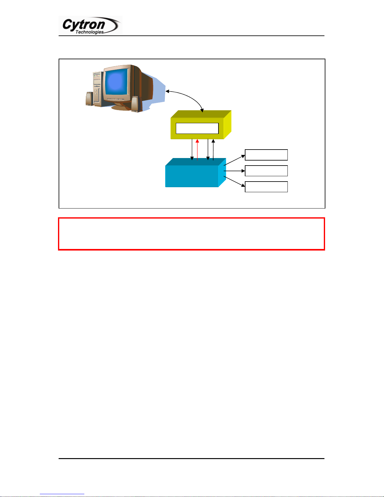
2. SYSTEM OVERVIEW
communication
UART
5V
USB Port
Cautions
ROBOT . HEAD to TOE
Product User’s Manual – UC00A
UC00A
UART
Application
5V MCU
Application
Application
not to use this power source to power application circuit or device. Wrong connection
such as wrong polarity, wrong voltage, shorted might permanently damage computer.
: “+” on UC00A is 5V supply directly from USB port of computer; it is advised
Created by Cytron Technologies Sdn. Bhd. – All Rights Reserved
Page 6
ROBOT . HEAD to TOE
4
Product User’s Manual – UC00A
3. PACKING LIST
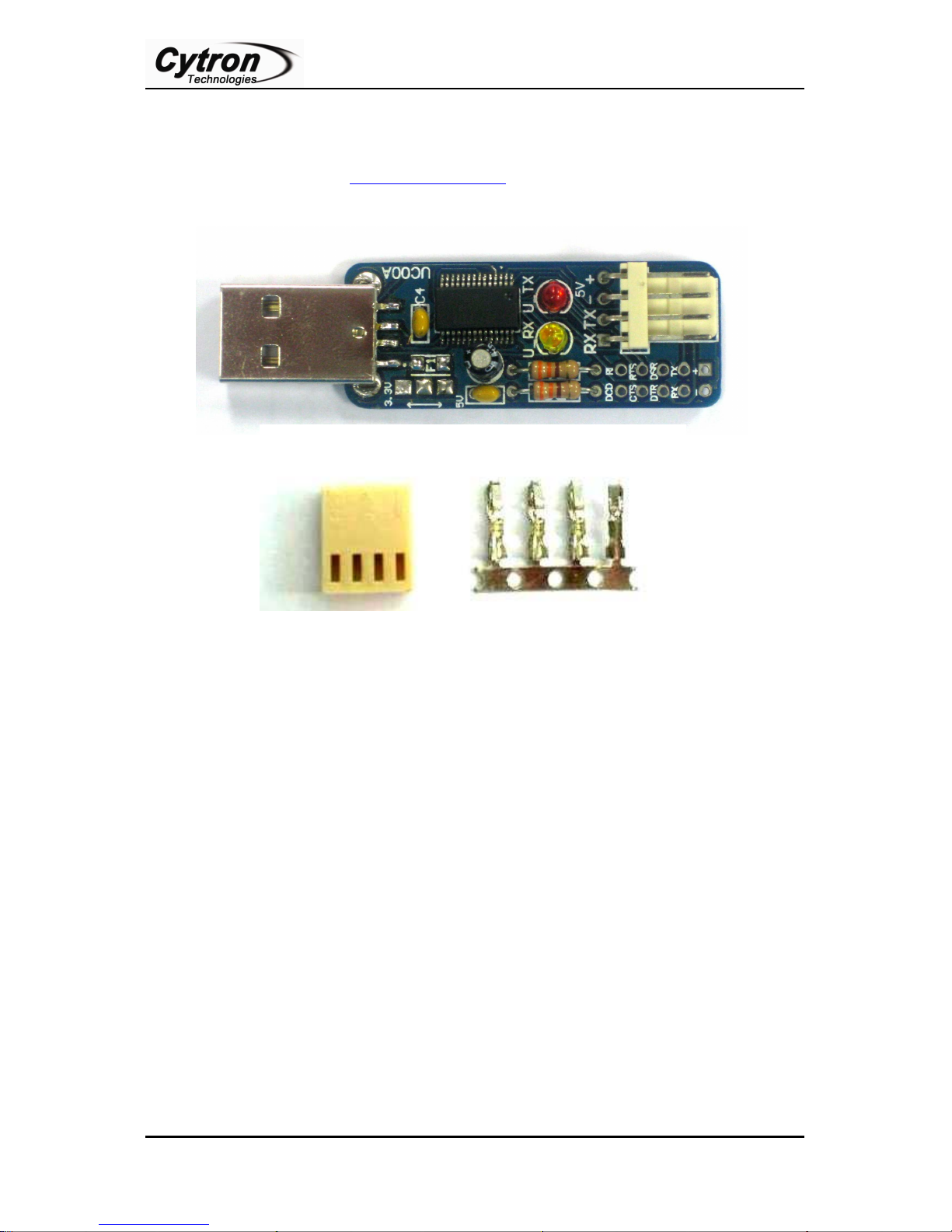
Please check the parts and components according to the packing list. If there are any parts
missing, please contact us at [email protected] immediately.
1. 1 x UC00A.
2. 1 x 2510 4 ways connector.
3. 4 x 2510 iron pins.
4. USB driver and User’s Manual should be downloaded from Cytron Website.
Created by Cytron Technologies Sdn. Bhd. – All Rights Reserved
Page 7
ROBOT . HEAD to TOE
5
A
B
C
D
Cautions
E
Product User’s Manual – UC00A
4. BOARD LAYOUT
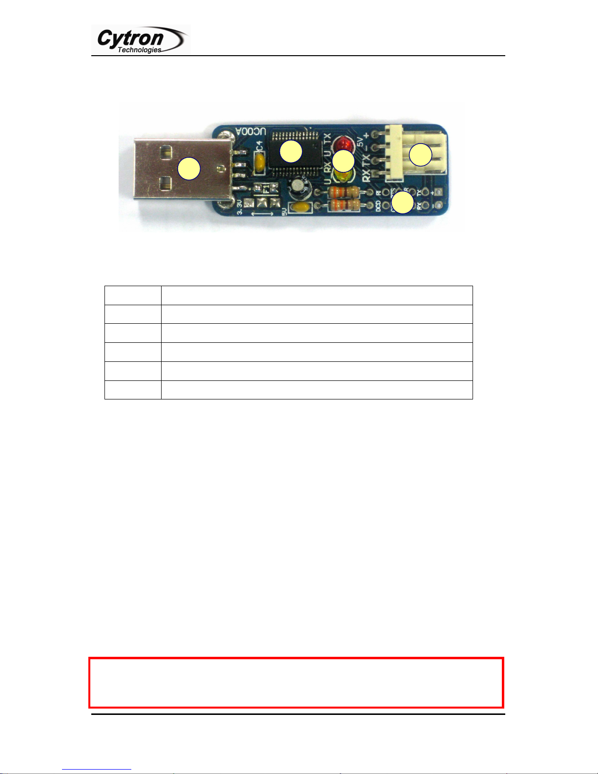
Label Function
A
B
USB A type (male).
USB to UART chip.
C
D
Two LED indicators for USB’s transmitter and receiver status.
4 ways header pin for interface to microcontroller.
E
2 x5 extension pad for extra COM Port Feature.
A – USB A type (male). This is for USB connection.
B – USB to UART converter chip.
C – These are a pair of small LED, red and yellow in color. These LEDs are connected to on
board USB to UART converter. It indicates the receiver and transmitter activity. It will only
work if UC00A is connected to PC or laptop through USB cable and microcontroller. Red
LED indicates USB’s transmitter send data, while yellow LED indicate USB’s receiver
receive data
D – 4 ways 2510 header pin for interface to microcontroller. Please refer to hardware
installation for detail connection.
E – 2 x 5 extension pad for extra COM Port Feature.
: “+” on UC00A is 5V supply directly from USB port of computer; it is advised
not to use this power source to power application circuit or device. Wrong connection
such as wrong polarity, wrong voltage, shorted might permanently damage computer.
Created by Cytron Technologies Sdn. Bhd. – All Rights Reserved
Page 8
ROBOT . HEAD to TOE
6
Cautions
Product User’s Manual – UC00A
5. PRODUCT SPECIFICATION
UC00A is designed to ease communication between microcontroller and PC. The
specifications are as listed below:
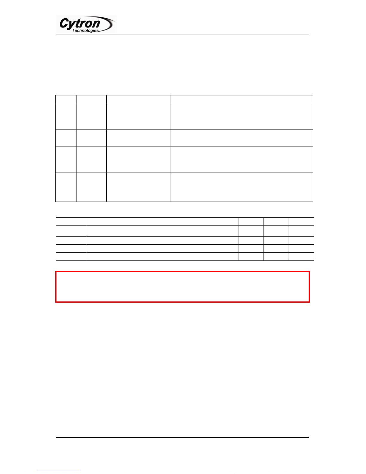
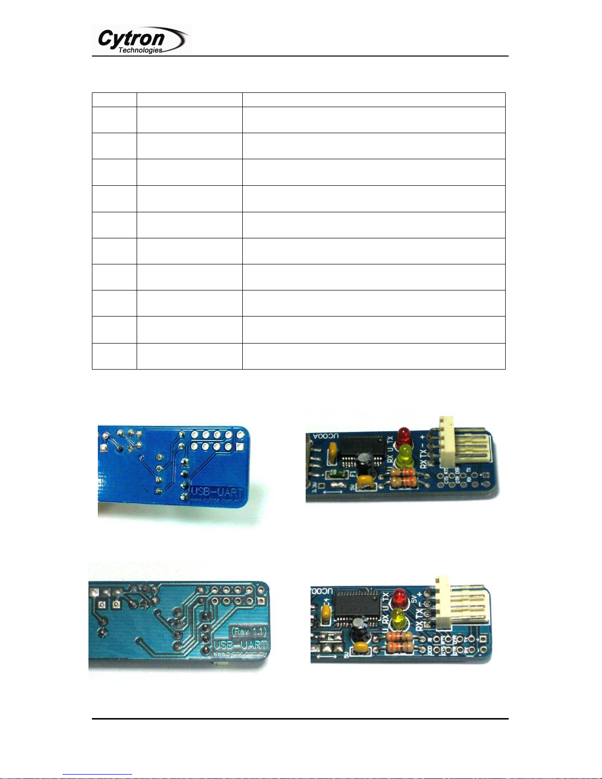
5.1 4 ways 2510 header pin
Pin Label Definition Function
1 +
2
– Ground or negative
3 TX
4 RX
5V Power output
from UC00A
UC00A UART
Transmit pin
UC00A UART
Receive pin
5V supply from USB, optional for user to power
external device, maximum current 200mA.
Ground of power and signal. This pin should be
connected to device’s GND pin.
This is UC00A’s transmitter pin (5V TTL). It
should be connected to device’s receiver pin.
This is UC00A’s receiver pin (5V TTL). It should
be connected to device’s transmitter pin.
Absolute Maximum Rating
Symbol Parameter Min Max Unit
+ Power output pin 5.0 5.0 V
- Operating voltage 0 0 V
TX Transmitter pin of UC00A 0 5.5 V
RX Receiver pin of UC00A 0 5.5 V
not to use this power source to power application circuit or device. Wrong connection
such as wrong polarity, wrong voltage, shorted might permanently damage computer.
: “+” on UC00A is 5V supply directly from USB port of computer; it is advised
Created by Cytron Technologies Sdn. Bhd. – All Rights Reserved
Page 9
Product User’s Manual – UC00A
7
UC00A Data Carrier
This pin is unused under normal UART operation.
5.2 2x5 Extension Pad
Label Definition Function
+
5V Power output
from UC00A
– Ground or negative
TX
RX
DSR
DTR
RTS
CTS
RI
UC00A UART
Transmit pin
UC00A UART
Receive pin
UC00A Data Set
Ready pin
UC00A Data
Terminal Ready pin
UC00A Request To
Send pin
UC00A Clear To
Send pin
UC00A Ring
Indicator pin
5V supply from USB, optional for user to power
external device, maximum current 200mA.
Ground of power and signal. This pin should be
connected to device’s GND pin.
This is UC00A’s transmitter pin (5V TTL). It should be
connected to device’s receiver pin.
This is UC00A’s receiver pin (5V TTL). It should be
connected to device’s transmitter pin.
This pin is unused under normal UART operation.
This pin is unused under normal UART operation.
This pin is unused under normal UART operation.
This pin is unused under normal UART operation.
This pin is unused under normal UART operation.
(This pin is available only for Rev 1.1 UC00A)
ROBOT . HEAD to TOE
DCD
Detect pin
(This pin is available only for Rev 1.1 UC00A)
* RI and DCD pin is available only for Rev 1.1 UC00A
Created by Cytron Technologies Sdn. Bhd. – All Rights Reserved
Page 10
ROBOT . HEAD to TOE
8
Cautions
Product User’s Manual – UC00A
Absolute Maximum Rating
Symbol Parameter Min Max Unit
+ Power output pin 5.0 5.0 V
- Operating voltage 0 0 V
RS232 Signals Signal Pins 0 5.5 V
not to use this power source to power application circuit or device. Wrong connection
such as wrong polarity, wrong voltage, shorted might permanently damage computer.
: “+” on UC00A is 5V supply directly from USB port of computer; it is advised
Created by Cytron Technologies Sdn. Bhd. – All Rights Reserved
Page 11
ROBOT . HEAD to TOE
9
1 2 3
4 5
7
6
8
9
Product User’s Manual – UC00A
6. INSTALLATION
6.1 Software Installation
UC00A used USB to UART chip and it require USB driver to be installed (1 time) on
computer. Thus, this section, user may refer to document name “Windows XP Installation
Guide” which provides users a simple procedure for installing drivers for this device driver
under Windows XP.
6.2 Hardware Installation
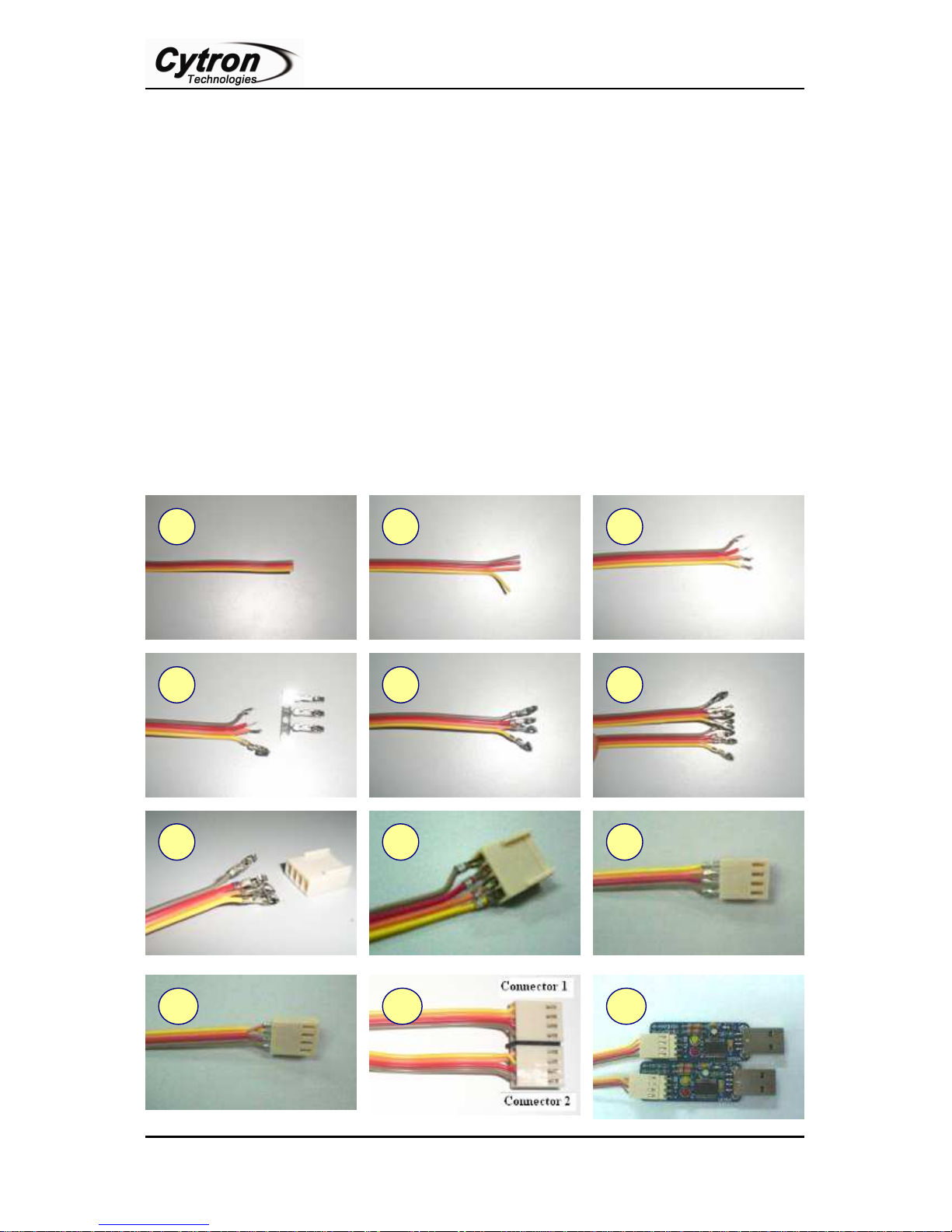
For interface with hardware or mictrocontroller, user need a cable to plug between UC00A
and hardware. Below are the picture and method of making 4 ways cabel. For step 6, repeat
step 1 to 5 for the other end of cable. Please start with the same side done in step (yellow on
bottom and the iron pin is facing up). For step 10 (second side of cable), nodes in pin 1 and 2
are switch with first side.
10
Created by Cytron Technologies Sdn. Bhd. – All Rights Reserved
12 11
Page 12
ROBOT . HEAD to TOE
10
Product User’s Manual – UC00A
7. GETTING STARTED
This section will show example on how to use UC00A. Generally, there are 2 methods to use
UC00A. It can be used to connect any 5V UART device to computer, or between 2
computers. Bare in mind that UC00A can be connected to any device which offer 5V UART
interface, this includes microcontroller, RFID reader, wireless module and more.
7.1 Using UC00A with microcontroller
This section will show an example using UC00A. UC00A will be connected to SKPS. SKPS
is a PS2 Controller Converter developed by Cytron Technologies. SKPS can be connected to
PC for functionality test. Normally, user will need to develop RS232 level shifter for
communication to serial port. This will generate extra work just to check the functionality of
SKPS. Furthermore, laptop and computer nowadays have phase-out the serial port, USB have
replaced it. Now, no extra work is required to check the functionally of SKPS. Simply plug
SKPS to UC00A and USB port of computer (PC or Laptop), install driver (1st time) and there
is an extra virtual COM port ready for SKPS. Checking functionality is simple as 1, 2, 3.
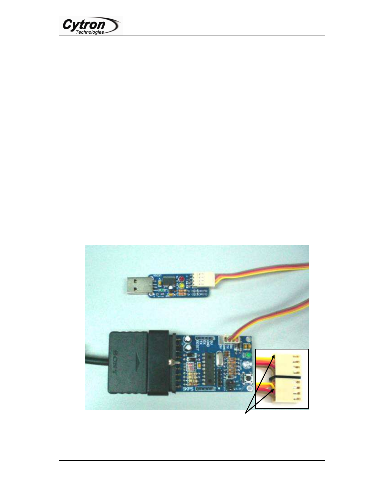
a. Simply connect UC00A to SKPS, another end (A type) of UC00A to PC as shown in
following figure. User might need to connect the RX and TX pin to UC00A. Of course,
these two pins should be cross connected to UC00A. In other words, RX of SKPS should
be connected to UC00A’s Transmitter pin (Tx), while TX of SKPS should be connected
to UC00A’s Receiver pin (Rx). No extra component is necessary between these
connections.
Wires in pin 1 and 2 are switch for the second connector.
b. Please refer to document named “USB Driver Installation Guide” for driver installation.
This is mention in section 6.1, software installation.
Created by Cytron Technologies Sdn. Bhd. – All Rights Reserved
Page 13
ROBOT . HEAD to TOE
11
Product User’s Manual – UC00A
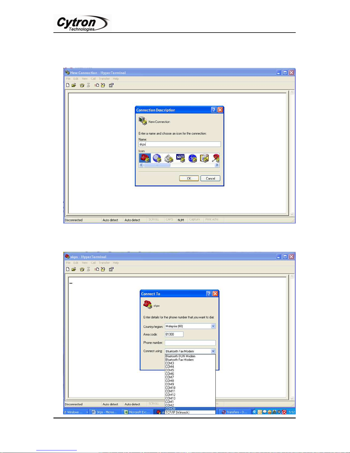
c. After plug in the UC00A to computer and installation of driver, user is ready to test the
functionality of SKPS. Open the HyperTerminal. Enter a name and choose an icon for
connection as picture below then click OK.
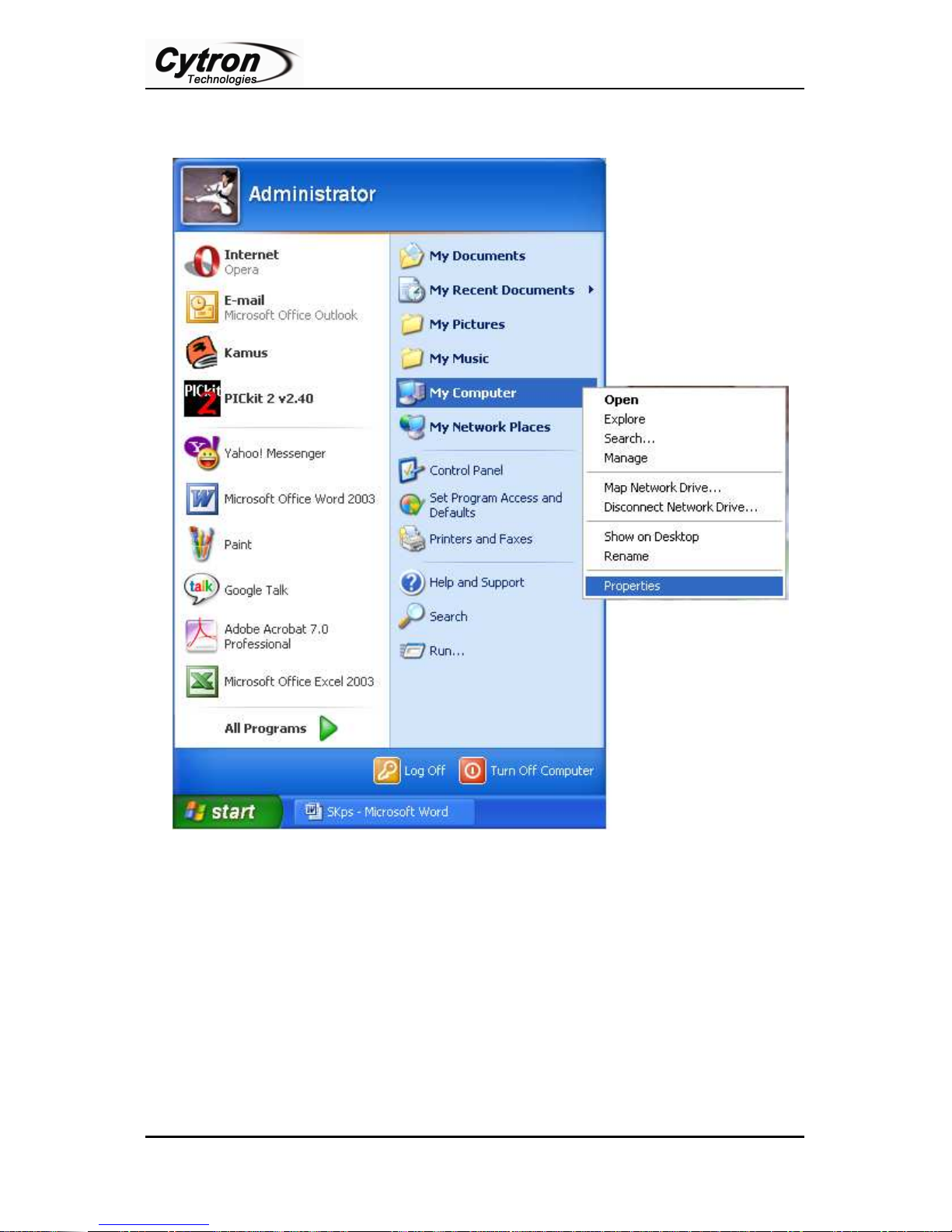
d. Connect using USB Serial Port. Please follow step from (e) to (g) if the COM port
number is not confirmed.
Created by Cytron Technologies Sdn. Bhd. – All Rights Reserved
Page 14
Product User’s Manual – UC00A
12
e. Go to Start, right click on My Computer and choose Properties.
ROBOT . HEAD to TOE
Created by Cytron Technologies Sdn. Bhd. – All Rights Reserved
Page 15
ROBOT . HEAD to TOE
13
Product User’s Manual – UC00A
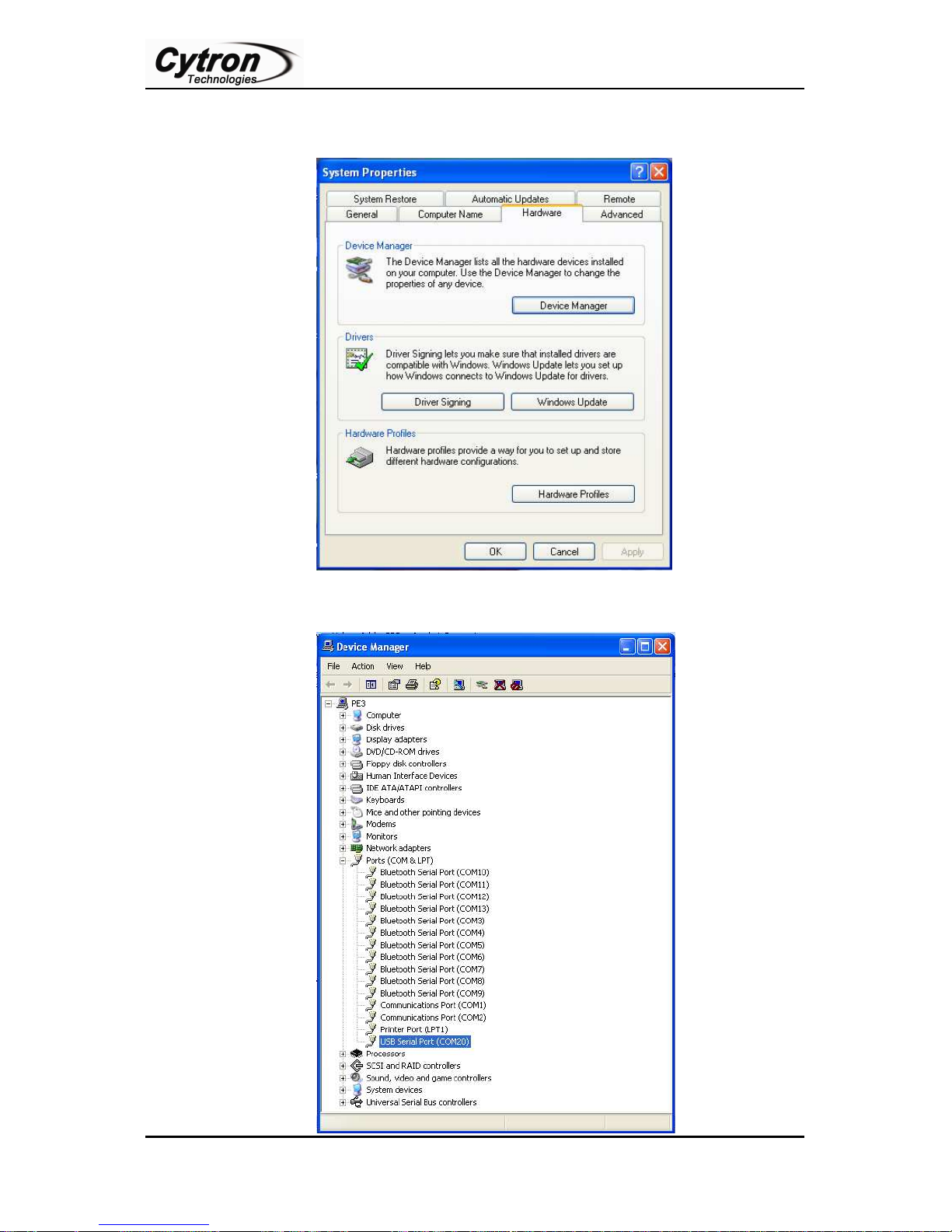
f. At System Properties Table, choose Hardware and click on Device Manager. Device
Manager Table will show out.
g. At Device Manager Table, choose Ports (COM & LPT) and USB Serial Port COM will
be visible. The Serial Port COM is “COM20” in this case.
Created by Cytron Technologies Sdn. Bhd. – All Rights Reserved
Page 16
ROBOT . HEAD to TOE
14
Product User’s Manual – UC00A
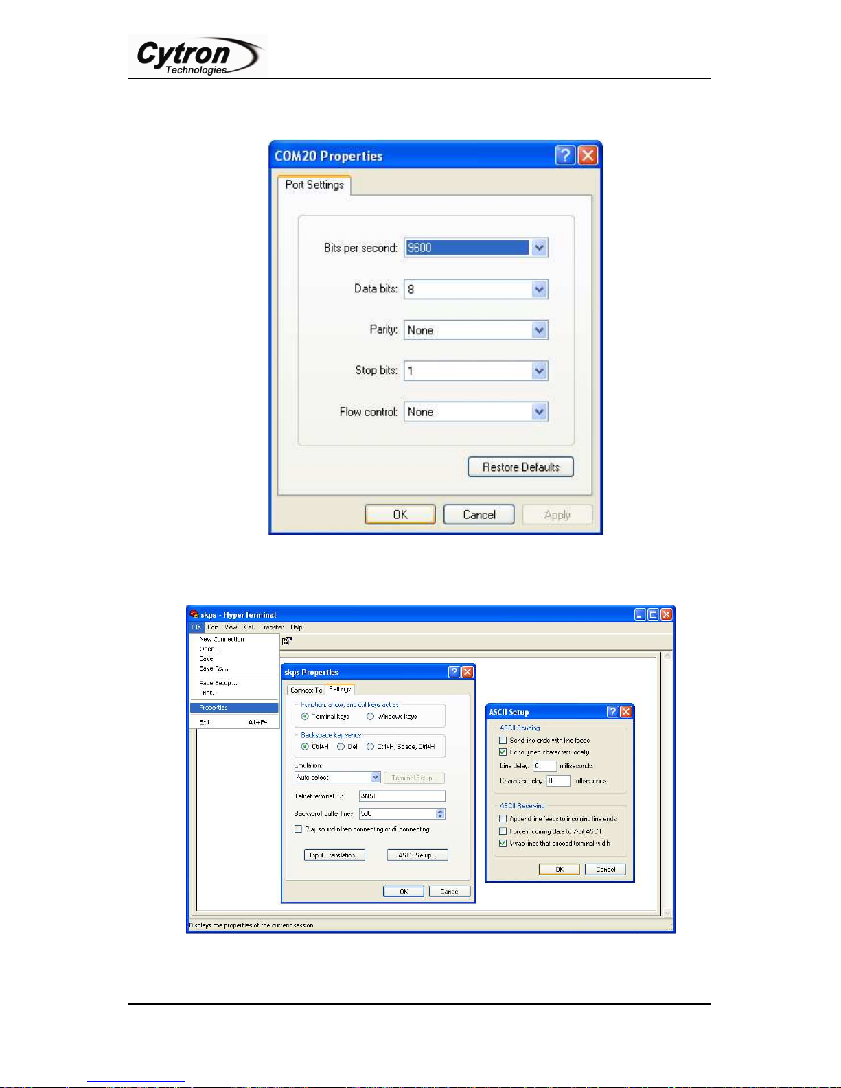
h. Set the Port Setting as picture below. Bits per second must be same with SKPS Baud Rate
and Flow control must be set to none. After finish setting, click Apply and then click OK.
i. Go to File and select Properties. SKPS Properties table will be shown. Choose Setting tab
and click ASCII Setup tab. Click on Echo typed characters locally and then click OK.
j. After all settings are complete, now SKPS is ready to communicate with PC and the
communication will be shown on HyperTerminal.
Created by Cytron Technologies Sdn. Bhd. – All Rights Reserved
Page 17
ROBOT . HEAD to TOE
15
Product User’s Manual – UC00A
7.2 Using UC00A for Communication between two PCs
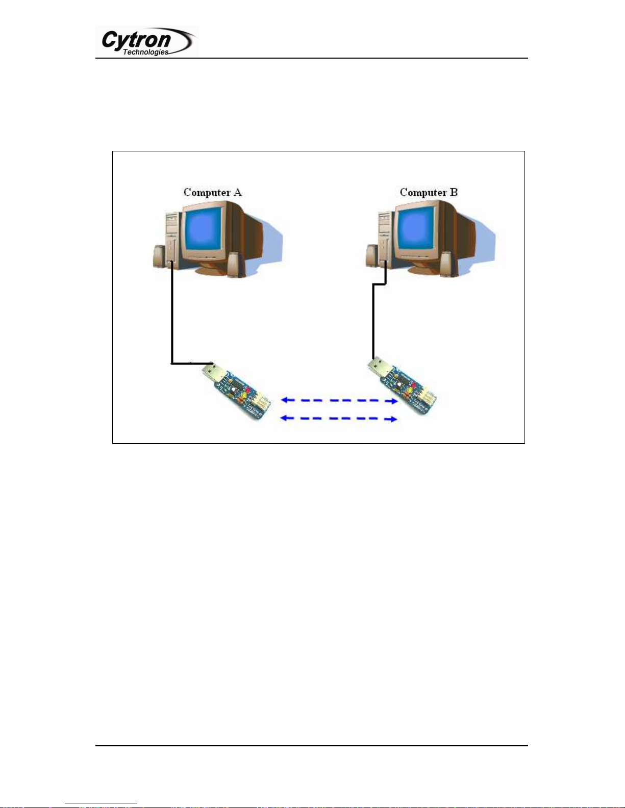
a. Two PCs can communicate to each other by connecting them to UC00A each. Connect
each PC like diagram below. Create a cable in section 6.2 and connect to UC00A, and
simply plug it to each PC.
b. Upon completion of connection, open HyperTerminal in each PC. Follow steps
mentioned in Section 7.1 (c) to (i). The baud rate for each PC must be same.
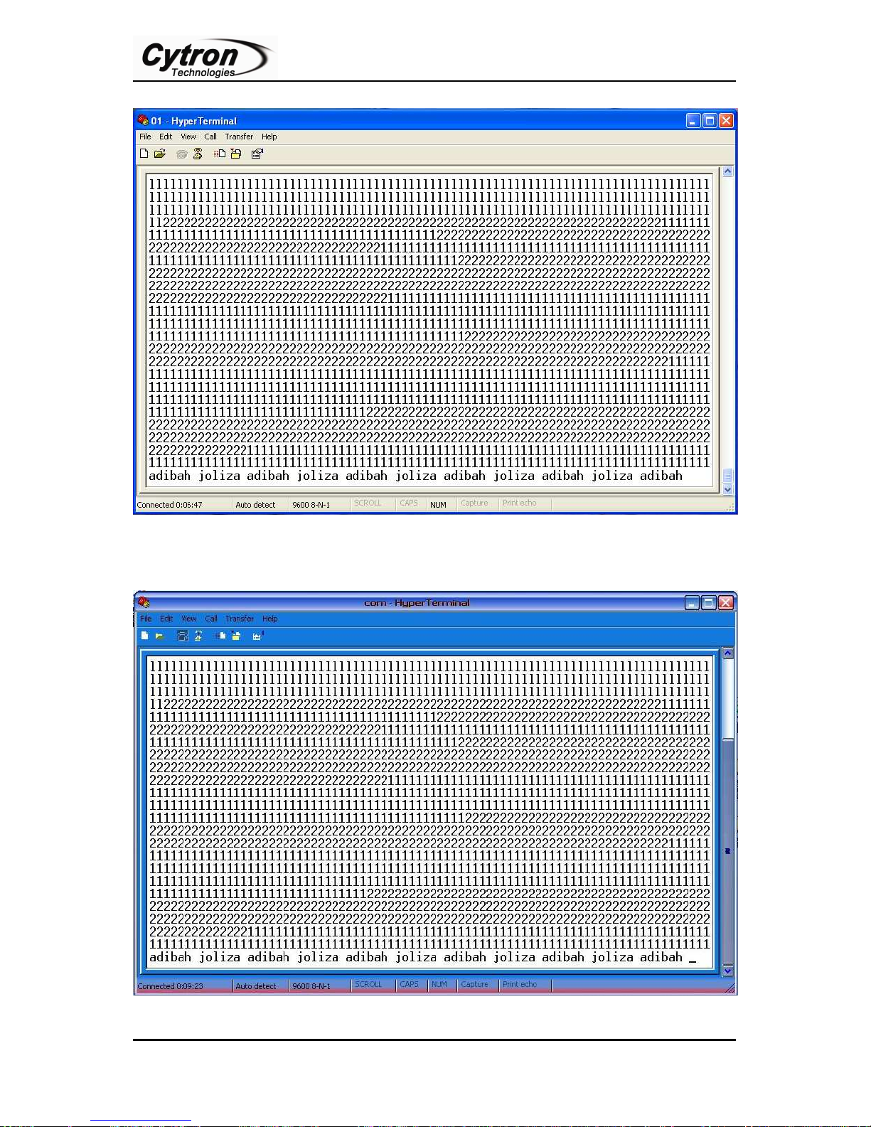
c. User may start typing any character in HyperTerminal, for example: chatting between two
PCs. Example computer 1 (C1) and computer 2 (C2) are connect. Any character typed in
HyperTerminal C1 will also shown in HyperTerminal C2. Pictures below show
HyperTerminal for each PC. Example C1 is adibah’s PC and C2 is joliza’s PC. C1 type
‘1’ and ‘adibah’ while C2 type ‘2’ and ‘joliza’. If Echo type characters locally is activate,
each HyperTerminal will shown like pictures below.
Created by Cytron Technologies Sdn. Bhd. – All Rights Reserved
Page 18
ROBOT . HEAD to TOE
16
Product User’s Manual – UC00A
(a) C1 HyperTerminal
(b) C2 HyperTerminal
Created by Cytron Technologies Sdn. Bhd. – All Rights Reserved
Page 19
17
8. WARRANTY
Prepared by
Product warranty is valid for 6 months.
Warranty only applies to manufacturing defect.
Damage caused by mis-use is not covered under warranty.
Warranty does not cover freight cost for both ways.
ROBOT . HEAD to TOE
Product User’s Manual – UC00A
Created by Cytron Technologies Sdn. Bhd. – All Rights Reserved
Cytron Technologies Sdn. Bhd.
19, Jalan Kebudayaan 1A,
Taman Universiti,
81300 Skudai,
Johor, Malaysia.
Tel: +607-521 3178
Fax: +607-521 1861
URL: www.cytron.com.my
Email: [email protected]
 Loading...