

Page 1
ROBOT . HEAD to TOE
Product User’s Manual – MDDS10
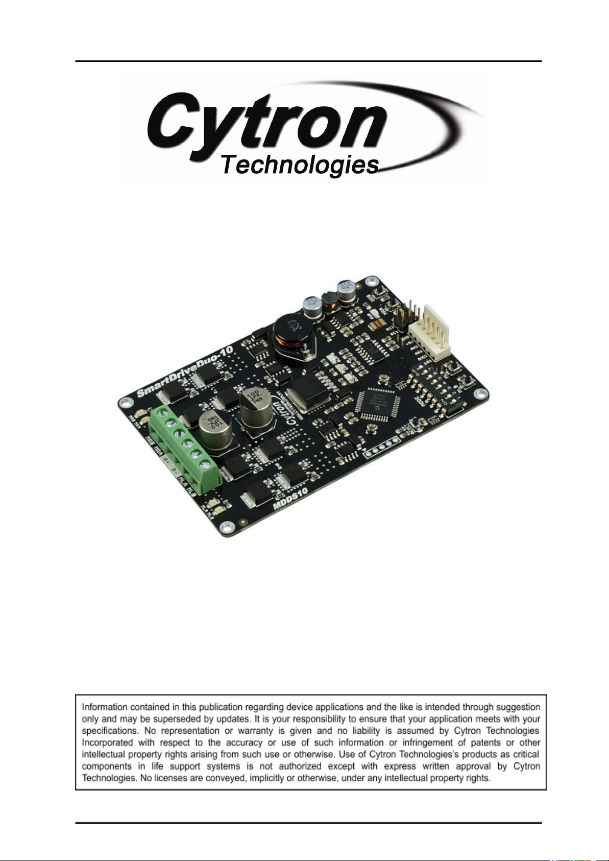
SmartDriveDuo-10
MDDS10
User's Manual
V1.1
September 2018
Created by Cytron Technologies Sdn. Bhd. – All Rights Reserved 1
Page 2

ROBOT . HEAD to TOE
Product User’s Manual – MDDS10
INDEX
1. Introduction 3
2. Packing List 4
3. Product Specifications 5
4. Board Layout 6
5. Power Supply 9
6. Motor Connection 10
7. Safety Features 11
8. Input Modes 12
a. RC Input Mode 14
b. Analog/PWM Input Mode 16
c. Simplified Serial Mode 18
d. Packetized Serial Mode 20
9. Warranty 22
Created by Cytron Technologies Sdn. Bhd. – All Rights Reserved 2
Page 3

ROBOT . HEAD to TOE
Product User’s Manual – MDDS10
1. INTRODUCTION
SmartDriveDuo-10 is one of the latest smart series motor drivers designed to drive medium
power brushed DC motor with current capacity up to 30A peak (10 seconds) and 10A
continuously. This driver is designed specially for controlling differential drive mobile robot
using RC controller. Nevertheless, MDDS10 can also be controlled using analog joystick or
microcontroller (PWM, Serial). MOSFETs are switched at 16 KHz to ensure quiet operation
and no annoying whining sound. Besides, it also equipped with a microcontroller unit to
provide smart features such as multiple input modes and thermal protection.
SmartDriveDuo-10’s feature makes driving a robot with differential drive a truly plug and
play experience.
Some of the features for SmartDriveDuo-10 are summarized as below:
● Bi-directional control for dual brushed DC motor.
● Support motor voltage from 7 to 35VDC.
● Maximum current up to 30A peak (10 seconds), 10A continuously.
● 16 KHz switching frequency for quiet operation.
● On board additional functions:
○ Battery low voltage indicator.
○ Battery over voltage indicator.
○ Thermal protection.
● Multiple input modes:
○ RC (Radio Control), 3.3 to 5.0V compatible
○ Analog voltage(0 - 5V) from potentiometer/variable resistor/joystick
○ PWM and DIR from microcontroller, supports both sign magnitude and
locked-antiphase, 3.3 to 5.0V compatible
○ TTL UART - Simplified Serial or Packetized Serial, 3.3 to 5.0V compatible
● On board push buttons for fast test and manual operation.
● No polarity protection for V motor.
Created by Cytron Technologies Sdn. Bhd. – All Rights Reserved 3
Page 4
ROBOT . HEAD to TOE
Product User’s Manual – MDDS10
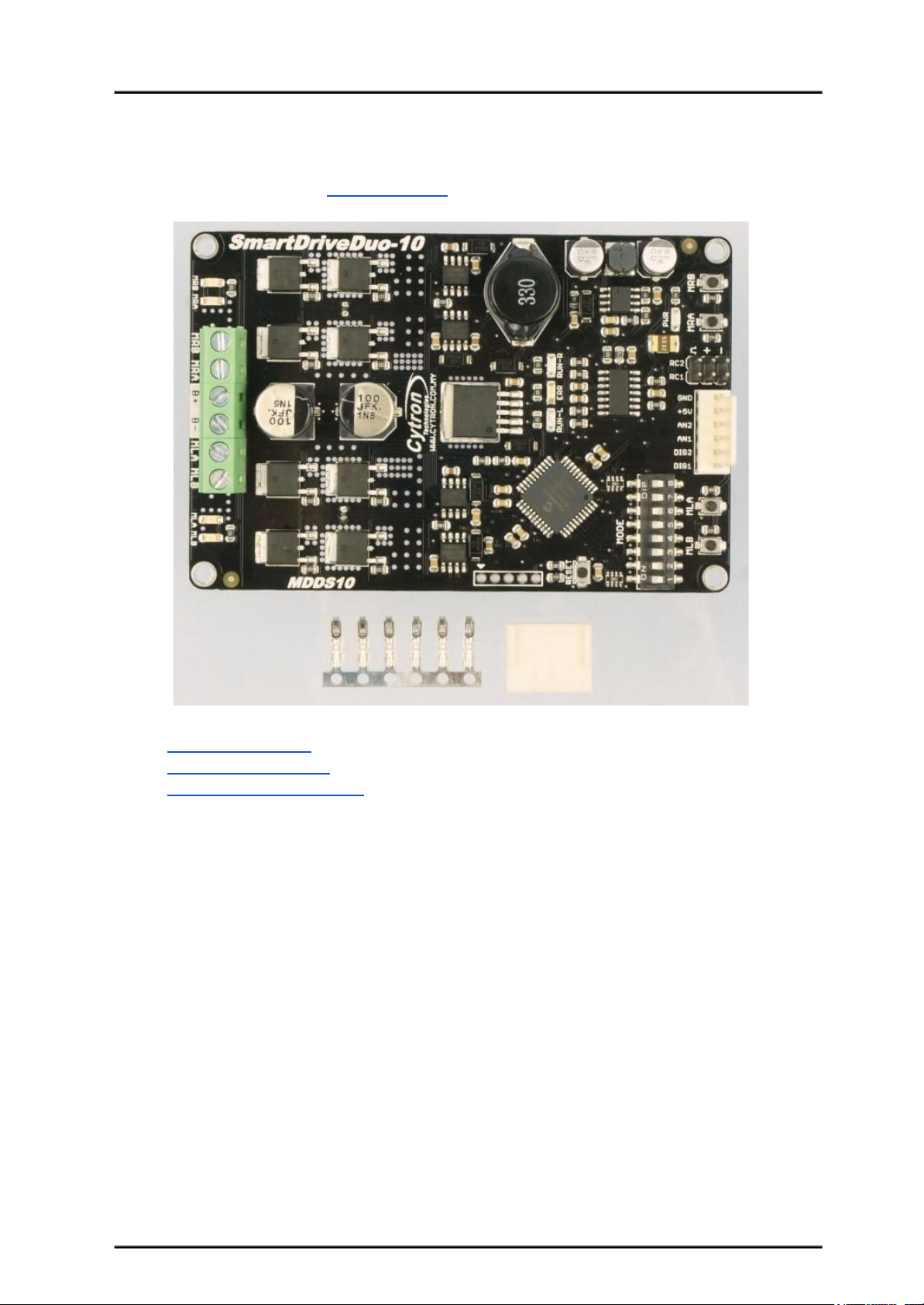
2. PACKING LIST
Please check the parts and components according to the packing list. If there are any parts
missing, please contact us at [email protected] immediately.
● 1 x SmartDriveDuo-10
● 6 x Terminal pin for 2510
● 1 x 6-way Connector Housing
Created by Cytron Technologies Sdn. Bhd. – All Rights Reserved 4
Page 5
ROBOT . HEAD to TOE
Product User’s Manual – MDDS10
3. PRODUCT SPECIFICATIONS
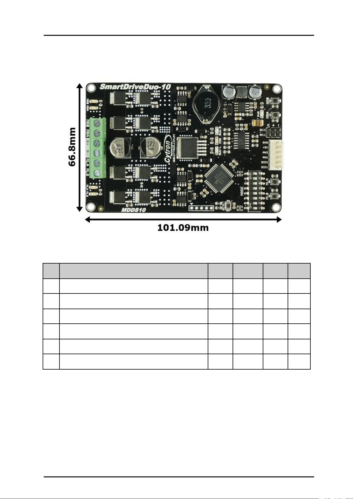
Dimension:
Absolute Maximum Rating of SmartDriveDuo-10
No
Parameters
Min
Typical
Max
Unit
1
Input Voltage (Motor Supply Voltage)
7-35V2
I
MAX
(Maximum Continuous Motor Current)*
--10A3
I
PEAK
– (Peak Motor Current) **
--30A4
V
IOH
(Logic Input – High Level)
1.3-5V5
V
IOL
(Logic Input – Low Level)
0-0.7V6
5V Output Current
--500
mA
* Depends on the room temperature.
** Must not exceed 10 second.
Created by Cytron Technologies Sdn. Bhd. – All Rights Reserved 5
Page 6
ROBOT . HEAD to TOE
Product User’s Manual – MDDS10
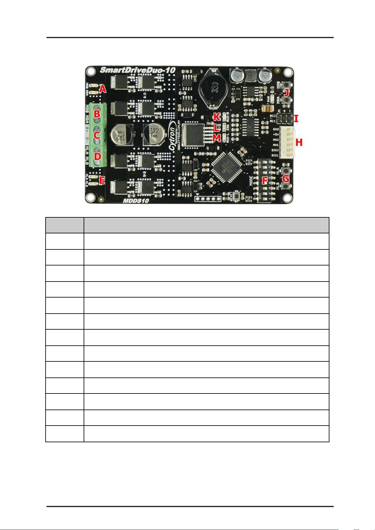
4. BOARD LAYOUT
Label
Function
A
Motor RIGHT LED Indicator
B
Motor RIGHT Terminal Block
C
Power Supply Terminal block
D
Motor LEFT Terminal Block
E
Motor LEFT LED Indicator
F
Mode Selection DIP Switch
G
Motor LEFT Test Button
H
Analog/PWM/Serial Input Pin
I
RC Input Pin
J
Motor RIGHT Test Button
K
Motor RIGHT Run LED
L
Error LED
M
Motor LEFT Run LED
Created by Cytron Technologies Sdn. Bhd. – All Rights Reserved 6
Page 7
ROBOT . HEAD to TOE
Product User’s Manual – MDDS10
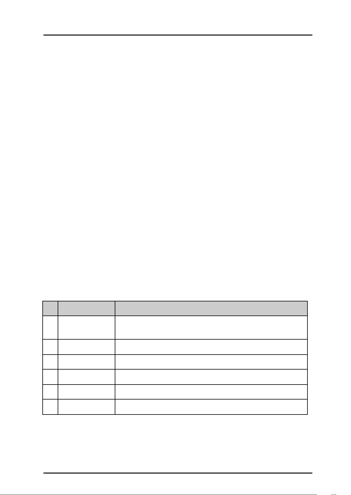
FUNCTION Description:
Motor RIGHT LED Indicator
Indication for current flow and direction for motor RIGHT. If LED MRA turns on, means
current flows from output MRA to MRB. Vice versa.
Motor RIGHT Terminal Block
Connect to motor RIGHT at your mobile robot. User can tie the wire to the terminal block or
solder the wire directly to the pad at bottom layer.
Power Supply Terminal Block
Connect to power source. User can tie the wire to the terminal block or solder the wire
directly to the pad at bottom layer. No polarity protection, please double check before power
up.
Motor LEFT Terminal Block
Connect to motor LEFT at your mobile robot. User can tie the wire to the terminal block or
solder the wire directly to the pad at bottom layer.
Motor LEFT LED Indicator
Indication for current flow and direction for motor LEFT. If LED MLA turns on, means
current flows from output MLA to MLB. Vice versa.
Mode Selection DIP Switch
User can select different input mode by setting the DIP switch.
Motor LEFT Test Button
Fast test to check driver functionality for motor LEFT. If MLA is pressed, current flows from
output MLA to MLB. Vice Versa.
Analog/PWM/Serial Input Pin
No
Pin Name
Description
1
DIG1*
1: Digital signal (Direction) for motor LEFT.
2: Serial Simplified, Serial Packetized.
2
DIG2
Digital signal (Direction) for motor RIGHT.
3
AN1
Analog/PWM signal for motor LEFT.
4
AN2
Analog/PWM signal for motor RIGHT.
5
+5V
+5V output. Do not connect to another 5V source.
6
GND
Ground.
*DIG1 can accept 2 types of input.
**Please refer to INPUT MODE section for more detail.
RC Input Pin
This pins specially for RC receiver input wire. RC1 for forward/reverse and RC2 for steering.
Created by Cytron Technologies Sdn. Bhd. – All Rights Reserved 7
Page 8
ROBOT . HEAD to TOE
Product User’s Manual – MDDS10
Motor RIGHT Test Button
Fast test to check driver functionality for motor RIGHT. If MRA is pressed, current flows
from output MRA to MRB. Vice Versa.
Motor RIGHT Run LED
Turns on when motor RIGHT is running. If signal error received for motor RIGHT, it will
blink.
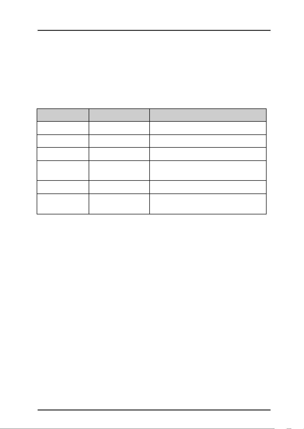
Error LED
Number of Blinks
Error
Description
Off
No Error
No error has been detected.
2
Input Error
Invalid or no input detected.
3
Under Voltage
The battery voltage is low.
4
Over Voltage
Supply voltage is over the limit. MDDS10
will not operate.
5
Over Temperature
Board temperature is high.
6
Shutdown
Board temperature is too high! Motor
automatically stop.
Motor LEFT Run LED
Turns on when motor LEFT is running. If signal error received for motor LEFT, it will blink.
Created by Cytron Technologies Sdn. Bhd. – All Rights Reserved 8
Page 9
ROBOT . HEAD to TOE
Product User’s Manual – MDDS10
5. POWER SUPPLY
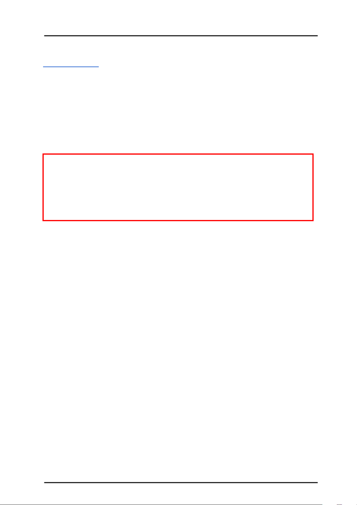
SmartDriveDuo-10 supports input voltage ranges from 7 to 35VDC. The recommended
power sources are:
● 6 – 18 cells NiMH or NiCd battery.
● 2 – 6 cells LiPo or Li-Ion battery.
● 7V – 35V sealed lead acid battery.
● 7V – 35V power supply (Must be in parallel with a battery with same voltage).
The power source can be connected to SmartDriveDuo-10 either via the terminal block, or
soldered directly to the pad at the bottom layer. There is no polarity protection on
MDDS10, please double check the connection before connecting to power source.
NOTE:
1. If a power supply that cannot sink current is being used (example: bench top and AC to
DC switching power supply), the input voltage will rise when the driver is regenerating
(motor is slowing down under load). Thus, it is important to connect a battery with
same voltage in parallel with the power supply to absorb the current generated by the
motor. Else, the input voltage might rise to a level where SmartDriveDuo-10 will be
destroyed permanently or the power supply trigger protection mode.
Created by Cytron Technologies Sdn. Bhd. – All Rights Reserved 9
Page 10

ROBOT . HEAD to TOE
Product User’s Manual – MDDS10
6. MOTOR CONNECTION
Similar to the power supply, connection to the motor can be made either via the terminal
block, or it can be soldered directly to the bottom layer pad.
For Mixed mode, especially for RC input mode (or Breakout board with Joystick soldered),
each terminal block must be connected to the same side of the motor. For example, left
terminal block connected to motor LEFT and right terminal block connected to motor
RIGHT. Then, user can test it by controlling the motor by using RC controller. If the motor
give wrong direction, reverse the polarity of the motor connection at the terminal block.
Created by Cytron Technologies Sdn. Bhd. – All Rights Reserved 10
Page 11
ROBOT . HEAD to TOE
Product User’s Manual – MDDS10
7. SAFETY FEATURES
SmartDriveDuo-10 incorporates some safety features which make it robust and reliable motor
driver. Below are the detailed descriptions for each feature.
a. Input Error (Error LED blinks 2 times)
Every time SmartDriveDuo-10 is power up, the input data must be ‘stop’ (for RC,
Analog, PWM input mode). This feature prevent the driver from sudden run,
especially when the driver accidently reset.
b. Under Voltage Warning (Error LED blinks 3 times)
Upon power on, SmartDriveDuo-10 will automatically detect the number of cells for
the battery. If it is set to LiPo, when the input voltage falls below 3.0V per cell during
operation, the error LED will blink to warn the user. However, the power to the motor
will be maintained and will not be cut out. Thus, it is user’s responsibility to stop the
motor driving and replace battery to avoid further damage to the battery. If other types
of battery is used to power the board (e.g NiMH, NiCD, SLA), the under voltage
warning will still be shown. In this case, user may ignore the warning and he/she
needs to estimate when to replace the battery by him/herself.
c. Over Voltage Protection (Error LED blinks 4 times)
If over voltage is detected (> 35V), SmartDriveDuo-10 will not operate.
d. Over Temperature Protection (Error LED blinks 5 times)
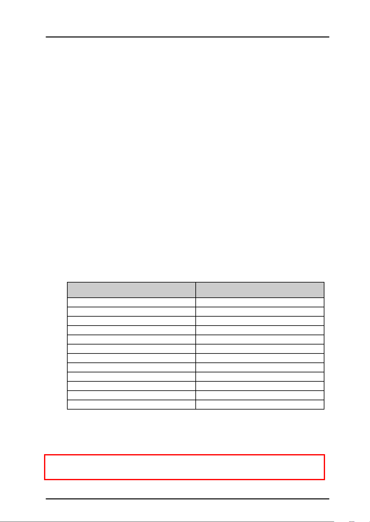
SmartDriveDuo-10 is equipped with a temperature sensor to monitor its operating
temperature. It will gradually lower down the duty cycle percentage base on the
temperature as shown below:
Temperature Range (oC)
Duty Cycle (%)
< 50
100
50 – 55
90
55 – 60
80
60 – 65
70
65 – 70
60
70 – 80
50
80 – 85
40
85 – 90
30
90 – 95
20
95 – 100
10
100 – 105
5
> 105
0 (Shutdown)
e. Shutdown (Error LED blinks 6 times)
Shutdown will occur when SmartDriveDuo-10 temperature become too high
(temperature > 105oC). As a result, motor will stop automatically. The driver for
respective channel starts operate again when temperature decrease less than 70oC.
Note: MDDS10 does not come with polarity protection, please double check the
connection before powering up.
Created by Cytron Technologies Sdn. Bhd. – All Rights Reserved 11
Page 12
ROBOT . HEAD to TOE
Product User’s Manual – MDDS10
8. INPUT MODE
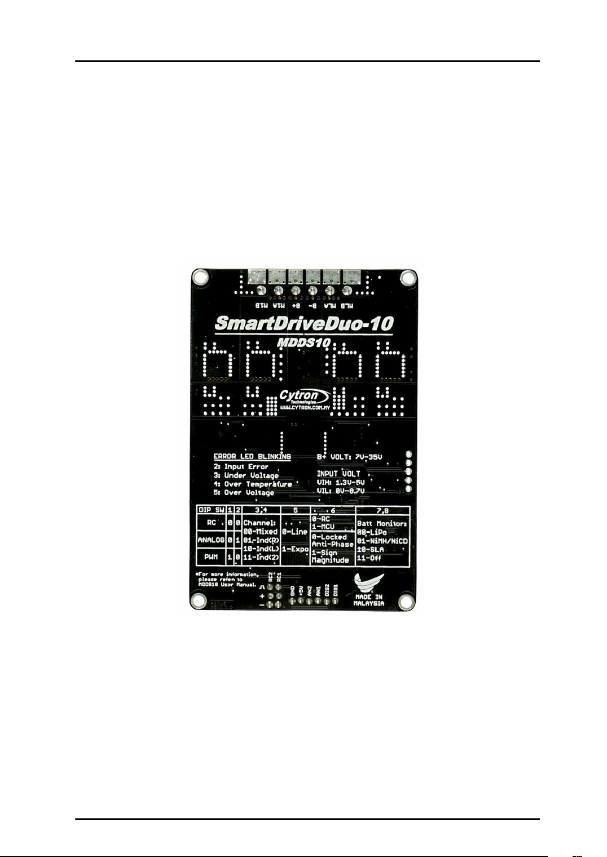
When the SmartDriveDuo-10 is powered up, RUN-L LED, ERR LED and RUN-R LED will
running once. After that, the input mode will be read from the DIP switch and retained as
long as the driver is powered. If you wish to change the input mode, you will need to change
the setting on the DIP switch and press the “RST” reset button, or power cycle the driver
(Turn it off and turn it on again).
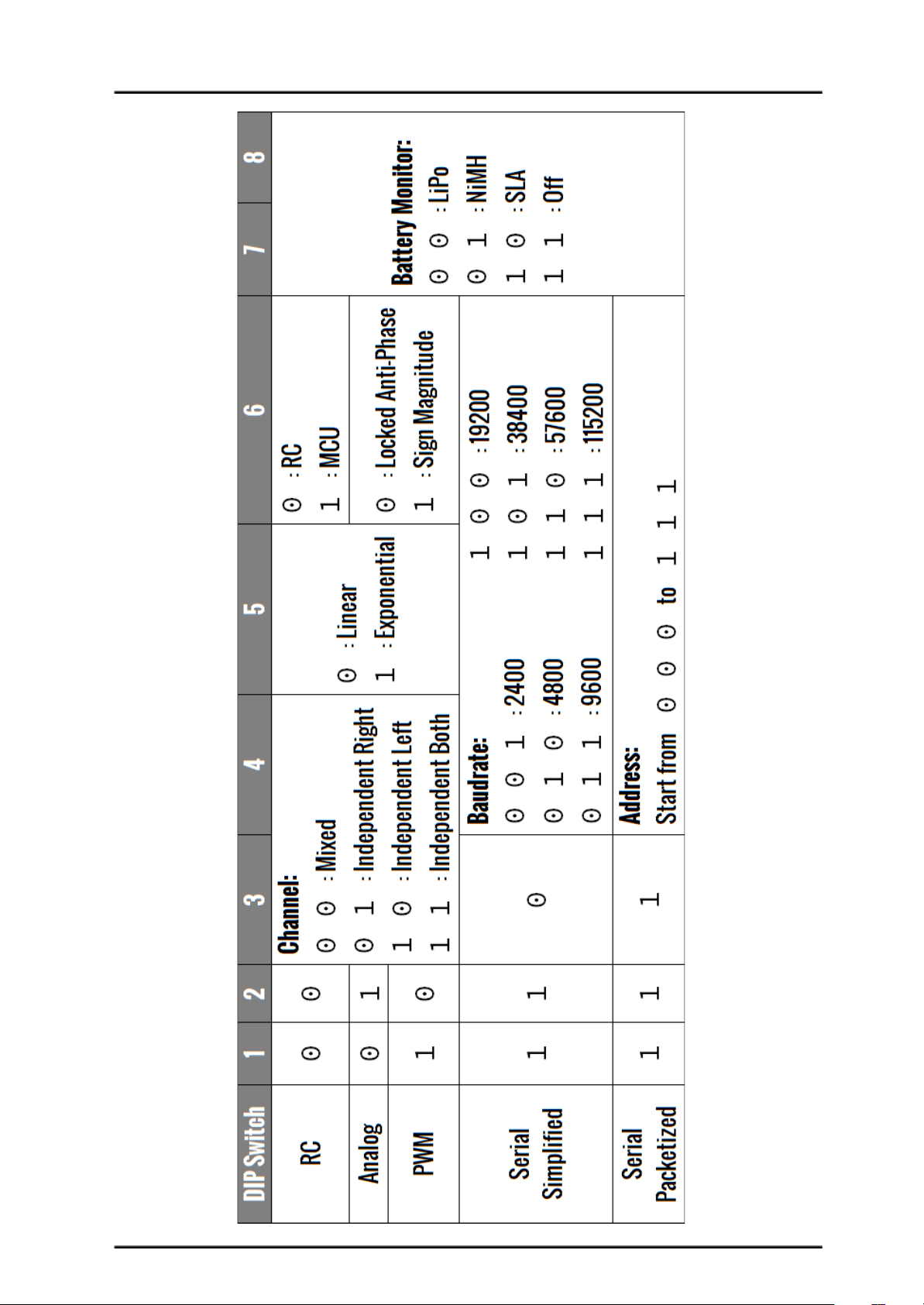
SmartDriveDuo-10 supports four different types of input mode (RC, Analog, PWM and
Serial). The DIP switch settings for each mode and the function for input pin are summarized
on the following page.
*You can find DIP switch setting and other information at the back of SmartDriveDuo-10
Created by Cytron Technologies Sdn. Bhd. – All Rights Reserved 12
Page 13
ROBOT . HEAD to TOE
Product User’s Manual – MDDS10
Created by Cytron Technologies Sdn. Bhd. – All Rights Reserved 13
Page 14
ROBOT . HEAD to TOE
Product User’s Manual – MDDS10
8.1 RC INPUT MODE
In RC input mode, the speed and direction of the motor is controlled by the signal from the
standard hobby radio control transmitter and receiver, or a microcontroller generating the
similar signal.
NOTE: The RC transmitter must be ON before power up the SmartDriveDuo-10.
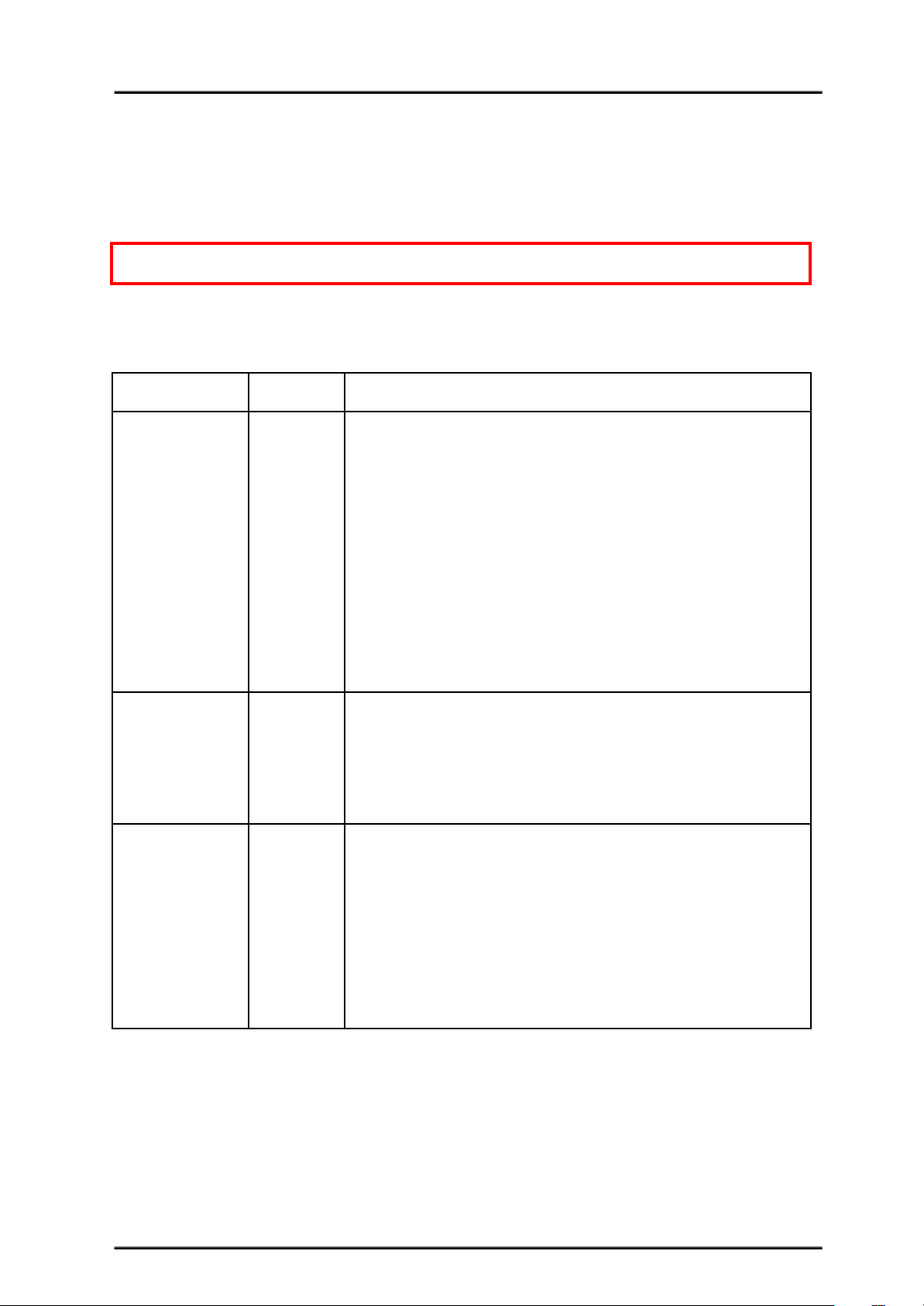
RC Input mode is selected by setting the SW1 & SW2 to 0 (Down). SW3 – SW6 can be
configured depending on the requirement of the user.
Input Mode
SW1:SW2
00
RC Input Mode
Single/Mix Mode
SW3:SW4
00
01
10
11
Mixed – The motor speed is controlled by channel RC1 and direction is
controlled by channel RC2. Recommended this mode if controlled using
RC transmitter/receiver.
Independent Right – Only motor Right will active, motor Left will
inactive. Motor Right is controlled by channel RC2.
Independent Left – Only motor Left will active, motor Right will
inactive. Motor Right is controlled by channel RC1.
Independent Both - Both motor is active and can be controlled
individually through channel RC1 and RC2. Recommended this mode if
controlled using Microcontroller.
Exponential Mode
SW5
0
1
Off – The speed is linear with the input signal. This is for low to
medium speed motor.
On –The response to input is exponential and thus soften the control
around the center zero speed point. This is suitable for high speed and
very sensitive motor.
MCU Mode
SW6
0
1
Off – The center point will be calibrated upon power up. Timeout
occurs after lost of signal for 100ms and the motor will be stopped for
safety purpose.
On – The center point is fixed at 1.5ms and the timeout feature is
disabled. Motor will continue to run with previous speed if new signal is
not detected. This is useful when a microcontroller is used to control the
motor. The microcontroller does not need to send the pulse continuously
to the SmartDriveDuo-10. Instead, it only needs to send a single pulse
when the speed or direction of the motor needs to be changed.
0 – OFF 1 – ON X – Don’t Care
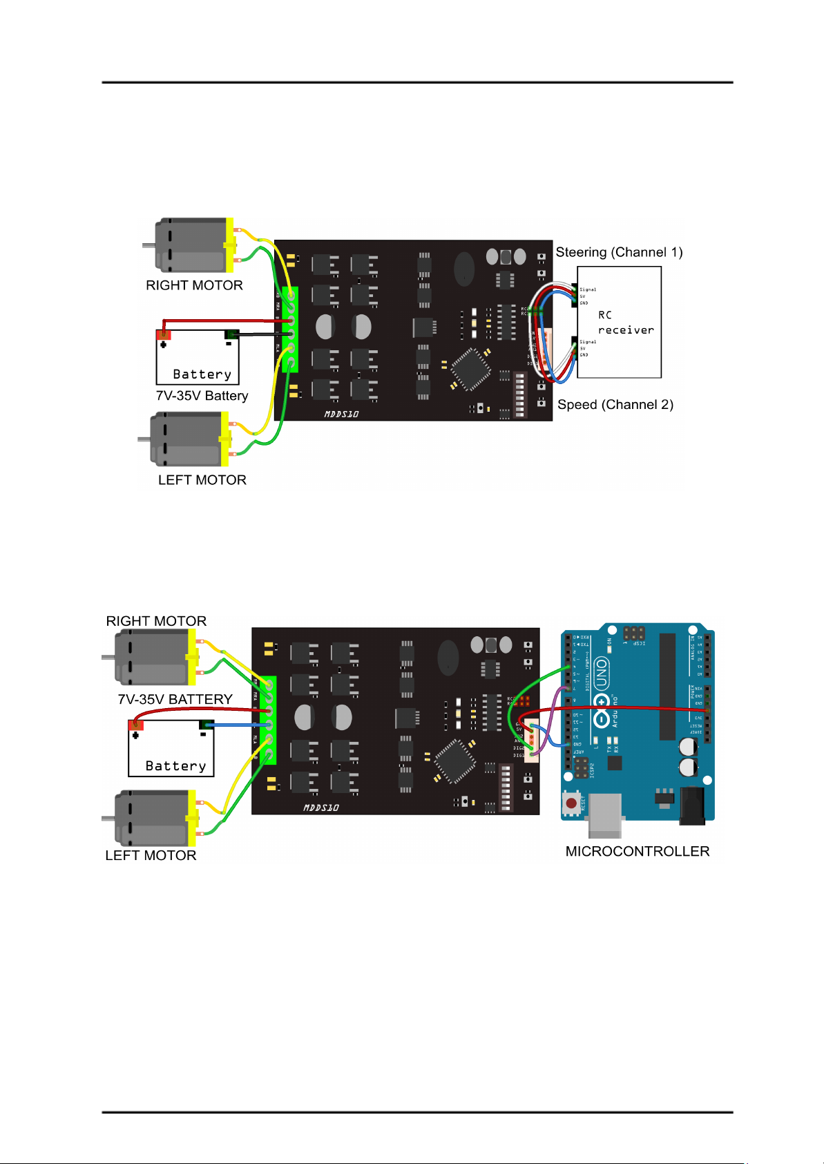
Figures below show the connection in RC mode.
Created by Cytron Technologies Sdn. Bhd. – All Rights Reserved 14
Page 15
ROBOT . HEAD to TOE
Product User’s Manual – MDDS10
RC Mode with RC Transmitter/Receiver (Mixed), DIP switch
1 2 3 4 5 6 7 8
0 0 0 0 0 0 0 0
RC Mode with Microcontroller (Independent Both), DIP switch
1 2 3 4 5 6 7 8
0 0 1 1 0 1 0 0
Created by Cytron Technologies Sdn. Bhd. – All Rights Reserved 15
Page 16
ROBOT . HEAD to TOE
Product User’s Manual – MDDS10
8.2 ANALOG/PWM INPUT MODE
In Analog/PWM input mode, the speed and direction of the motor is controlled by the analog
voltage or PWM signal. The valid input range is 0 – 5V and it’s very easy to control by using
a potentiometer. For example, the motor can be controlled by a joystick or foot pedal with
potentiometer.
NOTE: The Analog/PWM signal to stop the motor (2.5V if Sign-Magnitude mode is off,
0V otherwise) must be available when the SmartDriveDuo-10 is turned on. Else, the driver
will show Input Error until the correct signal is available.
Analog input mode is selected by setting SW1 to 0 (Down) and SW2 to 1 (Up). PWM input
mode is selected by setting SW1 to 1 (Up) and SW2 to 0 (Down). SW3 – SW6 can be
configured depending on the requirement of the user.
Input Mode
SW1:SW2
01
10
Analog Input Mode – The input is analog signal. The filter
capacitor is not connected and the input signal is not filtered.
SW1 is for Input 1 while SW2 is for Input 2.
PWM Input Mode – The input is PWM signal. The filter
capacitor is connected and the input signal is low pass filtered to
be an analog signal. SW1 is for Input 1 while SW2 is for Input 2.
SW2 must be set to 0 if Sign-Magnitude mode is turned on.
Single/Mix Mode
SW3:SW4
00
01
10
11
Mixed – The motor speed is controlled by channel RC1 and
direction is controlled by channel RC2. Recommended this mode
if controlled using Breakout board with Joystick soldered.
Independent Right – Only motor Right will active, motor Left
will inactive. Motor Right is controlled by channel RC2.
Independent Left – Only motor Left will active, motor Right
will inactive. Motor Right is controlled by channel RC1.
Independent Both - Both motor is active and can be controlled
individually through channel RC1 and RC2. Recommended this
mode if controlled using Microcontroller.
Exponential Mode
SW5
0
1
Off – The speed is linear with the input signal. This is for low to
medium speed motor.
On –The response to input is exponential and thus soften the
control around the center zero speed point. This is suitable for
high speed and very sensitive motor.
Sign-Magnitude
Mode
SW6
0
1
Locked Anti-Phase – Motor stops when the input signal is 2.5V.
Motor moves in one direction when the input is < 2.5V and in
another direction when the input is > 2.5V. Recommended this
mode if controlled using Breakout board with Joystick soldered.
Signed Magnitude – AN1 and AN2 controls the speed of the
motor. Motor stops when the input is 0V and run at full speed
Created by Cytron Technologies Sdn. Bhd. – All Rights Reserved 16
Page 17
ROBOT . HEAD to TOE
Product User’s Manual – MDDS10
when the input is 5V. DIG1 and DIG2 is digital inputs and it
controls the direction of the motor respectively.
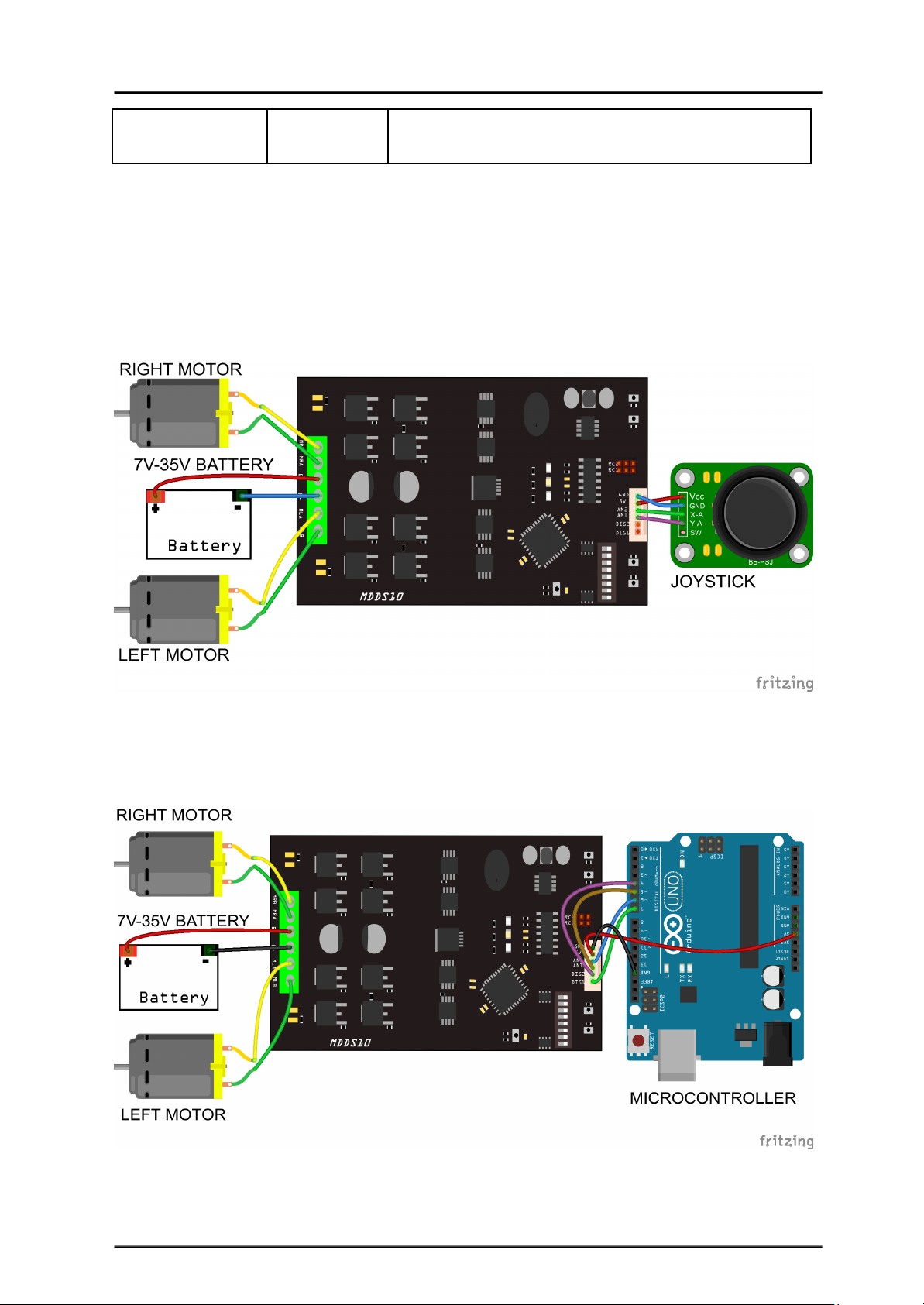
0 - OFF 1 - ON X - Don’t Care
Figures below show the connection in analog/PWM input mode.
Analog input mode with Joystick board (Mixed), DIP switch
DIP Switch Setting
1 2 3 4 5 6 7 8
0 1 0 0 0 0 0 0
PWM input mode with microcontroller (Independent Both), DIP switch
DIP Switch Setting
1 2 3 4 5 6 7 8
1 0 1 1 0 1 0 0
Created by Cytron Technologies Sdn. Bhd. – All Rights Reserved 17
Page 18
ROBOT . HEAD to TOE
Product User’s Manual – MDDS10
8.3 SERIAL SIMPLIFIED MODE
In Simplified Serial mode, SmartDriveDuo-10 is controlled by using the UART interface.
DIG1 pin is the UART Rx. DIG2, AN1 and AN2 pins are not used in this mode.
A single byte of data is all you need to control the speed and direction for each motor. First
MSB bit is to select which motor to control, and the rest bits is to control.
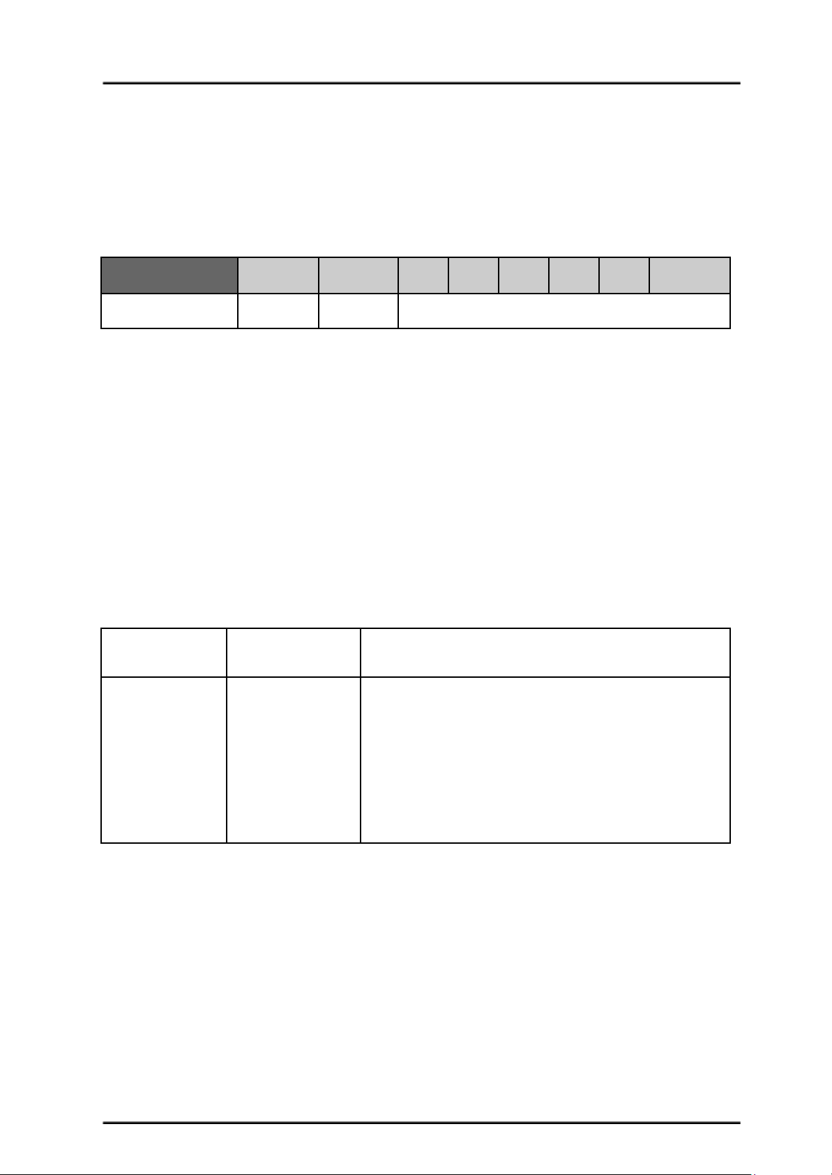
Bit
7 (MSB)
6543210 (LSB)
Function
Channel
Direction
Speed
Bit 7 (Channel): 0 - motor LEFT, 1 - motor RIGHT.
Bit 6 - 0: Control motor direction and speed.
Example: Value in Decimal
● 0 or 64 - motor LEFT stop.
● 63 - motor LEFT full forward.
● 127 - motor LEFT full reverse.
● 128 or 192 - motor RIGHT stop.
● 191 - motor RIGHT full forward.
● 255 - motor RIGHT full reverse.
Simplified Serial mode is selected by setting SW1, SW2 to 1 (Up) and SW3 to 0 (Down).
SW4 – SW6 are used to select the UART baud rate.
Input Mode
SW1 - SW3
110
Simplified Serial Mode
UART Baud Rate
SW4 - SW6
000
001
010
011
100
101
110
111
Baud Rate
1200
2400
4800
9600
19200
38400
57600
115200
0 - OFF 1 - ON X - Don’t Care
Created by Cytron Technologies Sdn. Bhd. – All Rights Reserved 18
Page 19
ROBOT . HEAD to TOE
Product User’s Manual – MDDS10
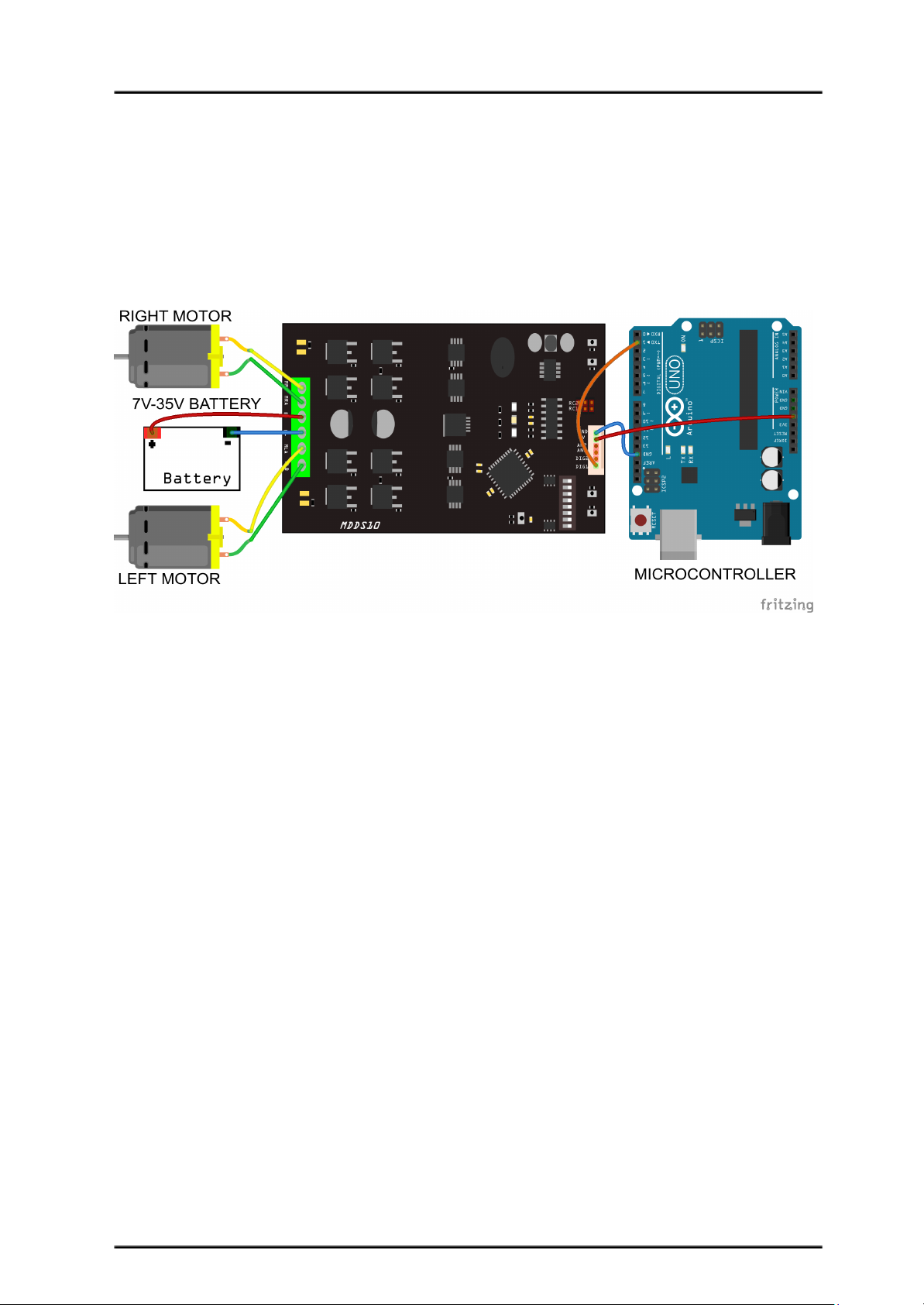
Figure below shows the connection to multiple SmartDriveDuo-10 in Simplified Serial
Mode.
Simplified Serial mode with microcontroller (9600bps), DIP switch
DIP Switch Setting
1 2 3 4 5 6 7 8
1 1 0 0 1 1 0 0
Created by Cytron Technologies Sdn. Bhd. – All Rights Reserved 19
Page 20
ROBOT . HEAD to TOE
Product User’s Manual – MDDS10
8.4 SERIAL PACKETIZED MODE
In Packetized Serial mode, SmartDriveDuo-10 is controlled by using the UART interface.
DIG1 pin is the UART Rx pin. DIG2, AN1 and AN2 pins are not used in this mode. To
control the motor, data sent to the driver must be in 4 bytes packet format which includes a
header, address, command and checksum. Up to 8 units of SmartDriveDuo-10 can be
connected together to a single microcontroller UART Tx pin.
Besides that, the SmartDriveDuo-10 also incorporates an Auto-Baud feature in Packetized
Serial mode. When the driver is first powered up, the host microcontroller must send a header
byte (Decimal 85 or hex 55) once to the driver. The driver will then calculate the baud rate
automatically based on this byte. After that, SmartDriveDuo-10 is ready to read full packet (4
bytes) and the baud rate cannot be changed without power recycle (power off and on) or reset
button.
NOTE:
1. When the driver is powered up and waiting for the header byte, the error LED will
blink and indicate that there is input error.
2. SmartDriveDuo-10 may take up to 500ms to start up after power is applied. Sending
the header byte for auto baud during this time period may cause undesirable results.
Please allow one-second delay between applying power and sending the header byte.
Packetized Serial mode is selected by setting SW1, SW2 and SW3 to 1 (Up). SW4 – SW6
are used to select the address.
Input Mode
SW1 - SW3
111
Packetized Serial Mode
UART Address
SW4 - SW6
000 - 111
0 - 7
0 - OFF 1 - ON X - Don’t Care
A packet consists of 4 bytes and the format is shown in the following table.
Byte
Name
Value (Decimal)
Description
1
Header
85
To indicate the start of packet.
2
Channel &
Address
Channel: Bit 3
Address: Bit 2 - 0
Used to identify the driver when multiple units are connected
together. The address bits (bit 2 - 0) must match the address
configured with the DIP switch. Bit 3 represent which motor
to be controlled, 0 for motor LEFT and 1 for motor RIGHT.
3
Command
0 – 255
Value 127 stops the motor, 0 is full reverse and 255 is full
forward.
4
Checksum
0 – 255
The value for checksum must be the result of
Header + Address + Command
Created by Cytron Technologies Sdn. Bhd. – All Rights Reserved 20
Page 21
ROBOT . HEAD to TOE
Product User’s Manual – MDDS10
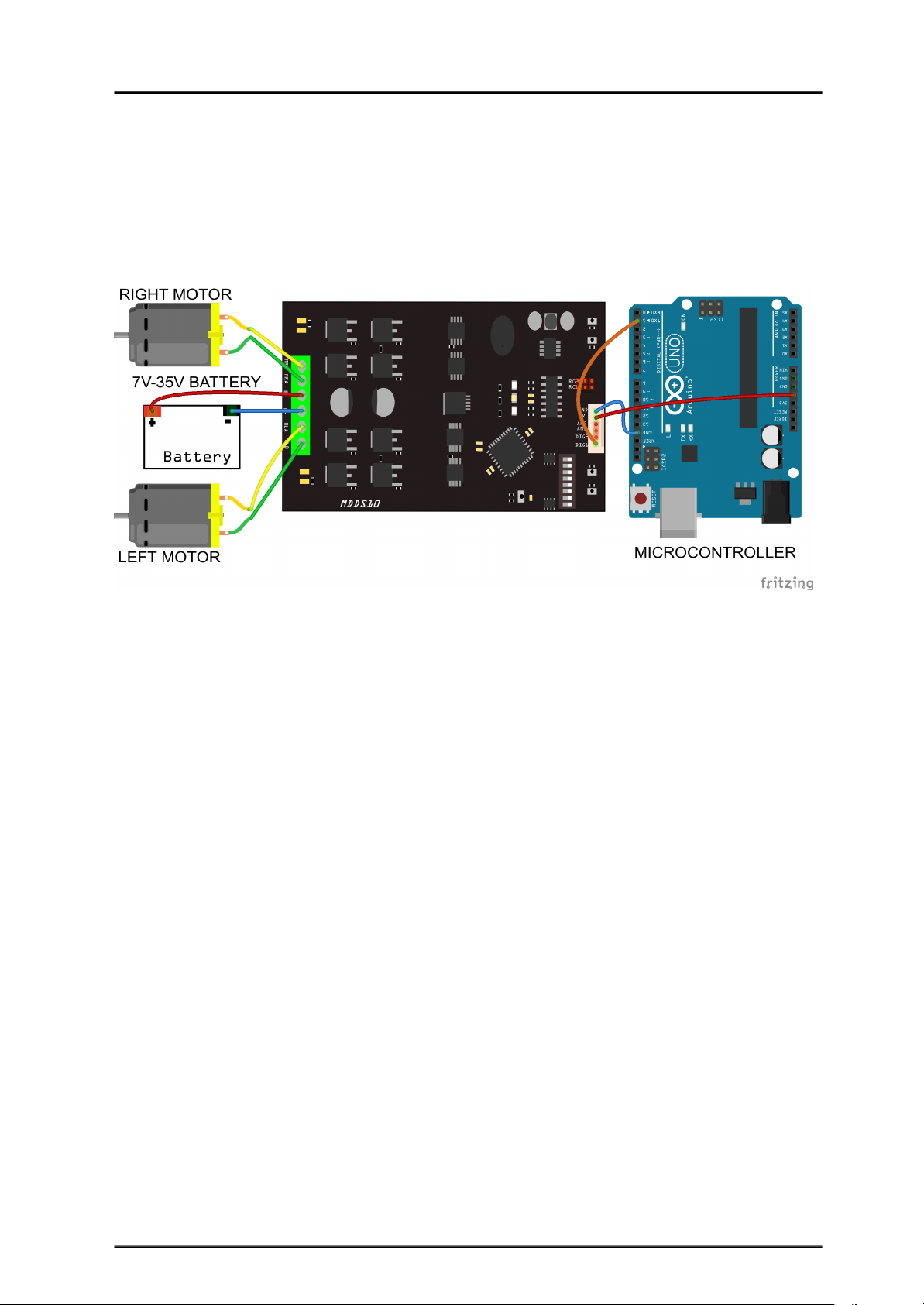
Figure below shows the connection to multiple drivers in Packetized Serial Mode.
Packetized Serial mode with microcontroller (Address = 0), DIP switch
DIP Switch Setting
1 2 3 4 5 6 7 8
1 1 1 0 0 0 0 0
Created by Cytron Technologies Sdn. Bhd. – All Rights Reserved 21
Page 22

ROBOT . HEAD to TOE
Product User’s Manual – MDDS10
9. WARRANTY
● Product warranty is valid for 12 months.
● Warranty only applies to manufacturing defect.
● Damaged caused by misuse is not covered under warranty
● Warranty does not cover freight cost for both ways.
Prepared by:
Cytron Technologies Sdn. Bhd.
No. 1, Lorong Industri Impian 1,
Taman Industri Impian,
14000 Bukit Mertajam,
Penang, Malaysia.
Tel: +604 - 548 0668
Fax: +604 - 548 0669
URL: www.cytron.io
Email: [email protected]
Created by Cytron Technologies Sdn. Bhd. – All Rights Reserved 22
 Loading...