

Page 1

Page 2

Hi .......................... ,
I'm Eng Tong from Cytron Technologies. I wrote this guide with you in mind - a
student (or teacher), learning Arduino for the first time.
When I first started learning Arduino, I discovered that there were lots of
documents, learning guides and tutorials available on the Internet - and ironically,
that was my biggest problem! There were simply too many that I had no idea
where to start and which one to refer to.
And many of the learning guides that claim to be crafted for beginners are just
too superficial - most of the time, they only show you the schematics, give you the
sample code and tell you what to expect but they do not explain how it works.
It's very frustrating for people like me who do not have C-programming
background. Although I can achieve the expected outcomes by following the
schematic and copying the code given, I'm pretty sure I will not be able to create
my own projects even after I've completed all the lessons.
Furthermore, I observed that most of the learning guides were written by
techies who tend to assume certain things to be understood. In other words,
foundational knowledge is not covered and what is presented is too technical for a
beginner to understand.
There's nothing special with the projects in this learning guide. Basically, I just
added explanation on some aspects that I initially struggled with and I also
simplified the technical part for better understanding. I sincerely hope that
beginners can benefit from this learning guide and enjoy learning Arduino.
Cheers,
Tan Eng Tong
Co-founder and CEO
Cytron Technologies
Page 3

Explore STEM and Coding
with Maker UNO
Xperiment Kit
Written by ET Tan
Edited by Cheryl Ng
Illustrated by Suhana Oazmi
v1.4 February 2020
Published by Cytron Technologies
Page 4

OVERVIEW
LESSON 0 SETTING UP
Hardware ....................................................................................... 6
Software - Arduino IDE and Driver ................................................. 7
LESSON 1 DIGITAL OUTPUT
Project 1: Turn On An LED............................................................... 14
Project 2: Blink An LED.................................................................... 18
Project 3: Blink the LEDs In Sequence ........................................... 21
LESSON 2 DIGITAL INPUT
Project 4: On-board Pushbutton Switch........................................... 27
Project 5: External Pushbutton Switch............................................. 30
LESSON 3 ANALOG OUTPUT
Project 6: Construct An LED Circuit................................................. 36
Project 7: Fade An LED................................................................... 40
LESSON 4 MELODY TONE
Project 8: Compose Basic Tone ...................................................... 47
Project 9: Compose "Happy Birthday" Melody................................. 51
Project 10: Optimize Your Code....................................................... 54
LESSON 5 ANALOG INPUT
Project 11: Display Analog Value On Serial Monitor......................... 61
Project 12: Read Analog IR Sensor................................................. 65
Project 13: IR Sensor To Detect Black Line..................................... 68
LESSON 6 DC MOTOR
Project 14: Control A DC Motor........................................................ 76
Project 15: Controlling A Motor Speed Using A Pushbutton............. 82
LESSON 7 ULTRASONIC SENSOR
Project 16: Setting Up Ultrasonic Sensor......................................... 89
Project 17: Build A Car's Rear Bumper Sensor................................ 97
Simplifying Digital Making
Page 5

LESSON 0
SETTING UP
HARDWARE
& SOFTWARE
Page 6
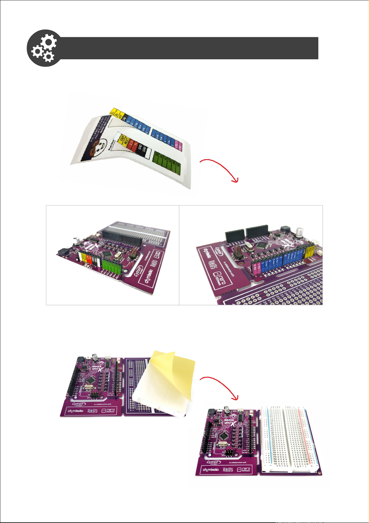
Part 1: Labelling Stickers and Breadboard
1. Peel off the labelling stickers and attach them to the pin headers as
shown below.
2. Take out the breadboard, remove the adhesive backing and then
attach it to the Maker UNO X board.
6Simplifying Digital Making
Page 7
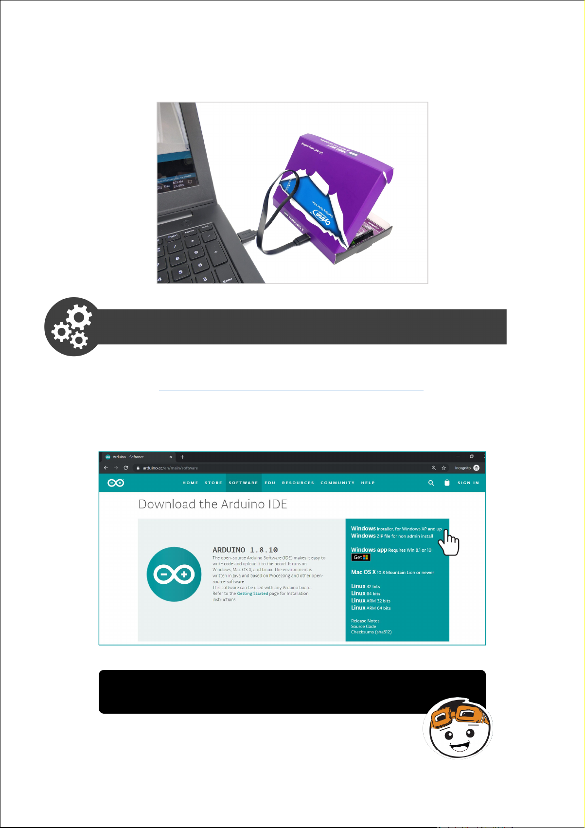
3. Connect Maker UNO X to your PC with a micro USB cable.
Part 2: Download & Install Arduino IDE
1. Go to https://www.arduino.cc/en/main/software.
2. Choose your OS to proceed.
For Windows Users, it is recommended to select Windows
Installer, for Windows XP and up.
7Simplifying Digital Making
Page 8
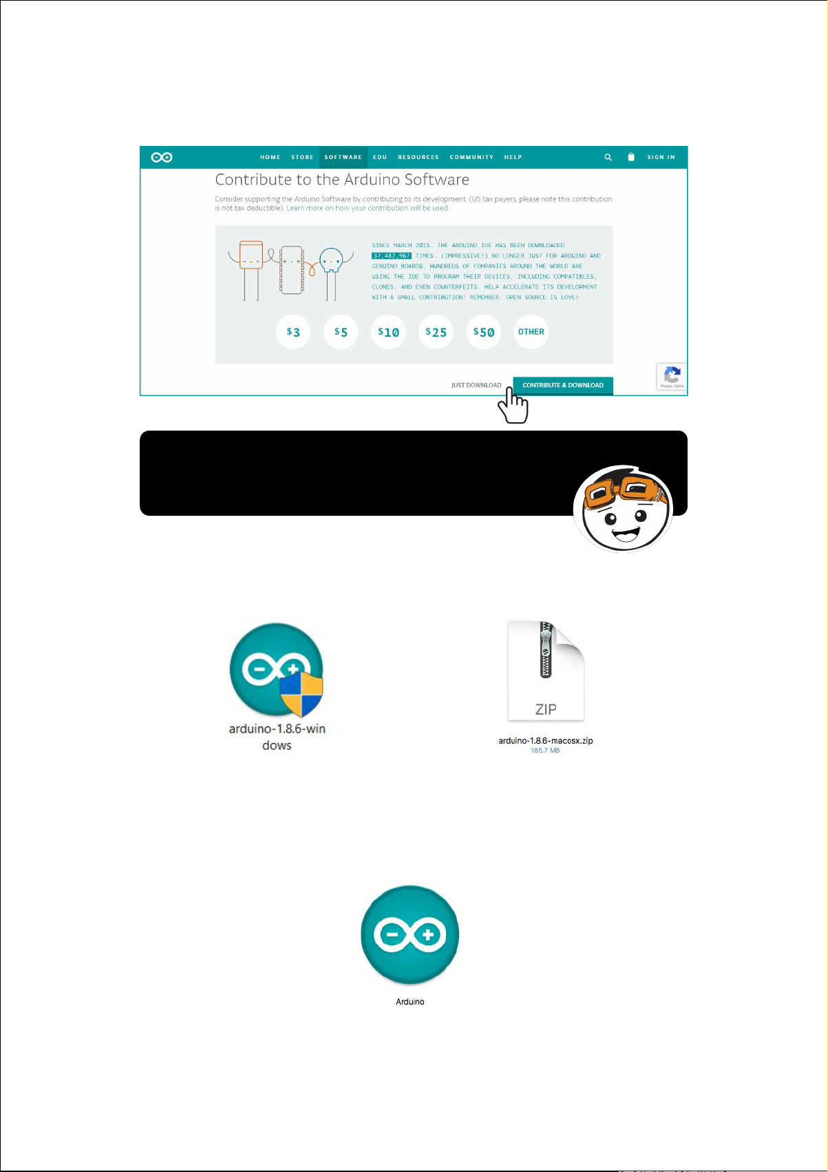
3. Arduino IDE is an open source software. Click “JUST DOWNLOAD”
button to download and use for free.
Note: Users are encouraged to make a monetary
contribution to help them to continue funding the
development.
4. Double click on the downloaded file to proceed.
For Windows For Mac
5. Once installation is completed, the Arduino icon will appear. Double
click the icon to launch Arduino IDE.
8Simplifying Digital Making
Page 9
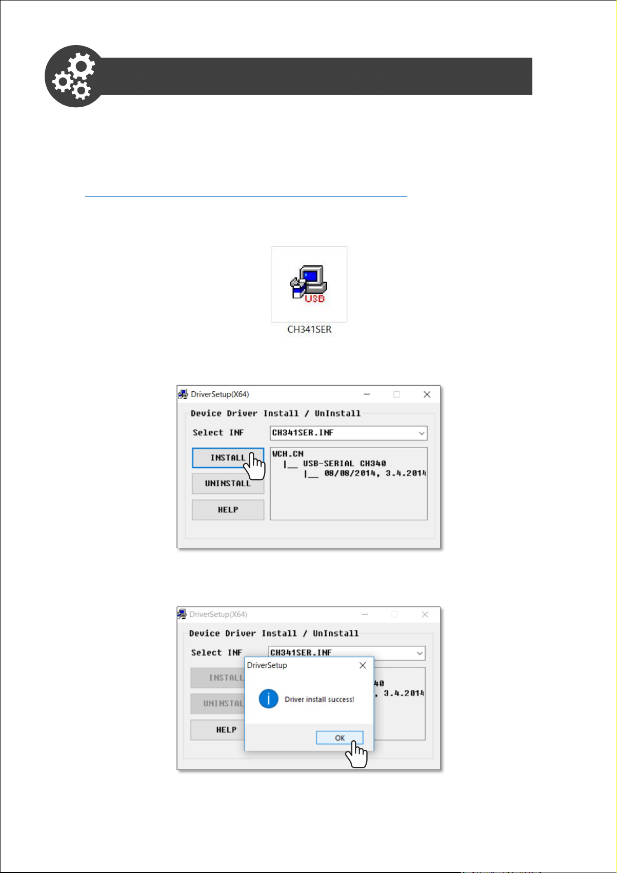
Part 3: Download & Install Driver
For Windows Users:
1.Download the driver here:
https://cdn.cytron.io/makeruno/CH341SER.EXE
2.Double click the “CH341SER” file to begin installation.
3.Click “INSTALL”.
4.Click “OK”.
9Simplifying Digital Making
Page 10
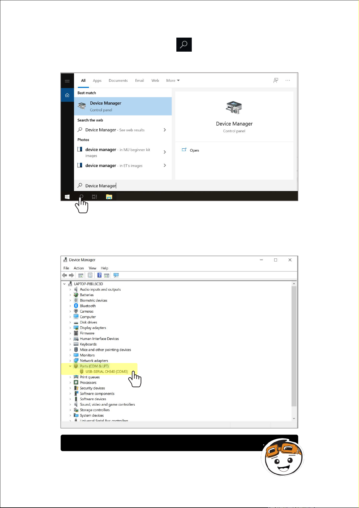
5. Click on Windows Search icon and search for “Device
Manager”.
6. Click to expand “Ports (COM & LPT)”. Check which port the CH340
driver has been assigned to. Take note of the COM number (for
example, the driver is linked to my COM3).
Your Maker UNO X needs to be connected to your PC.
10Simplifying Digital Making
Page 11
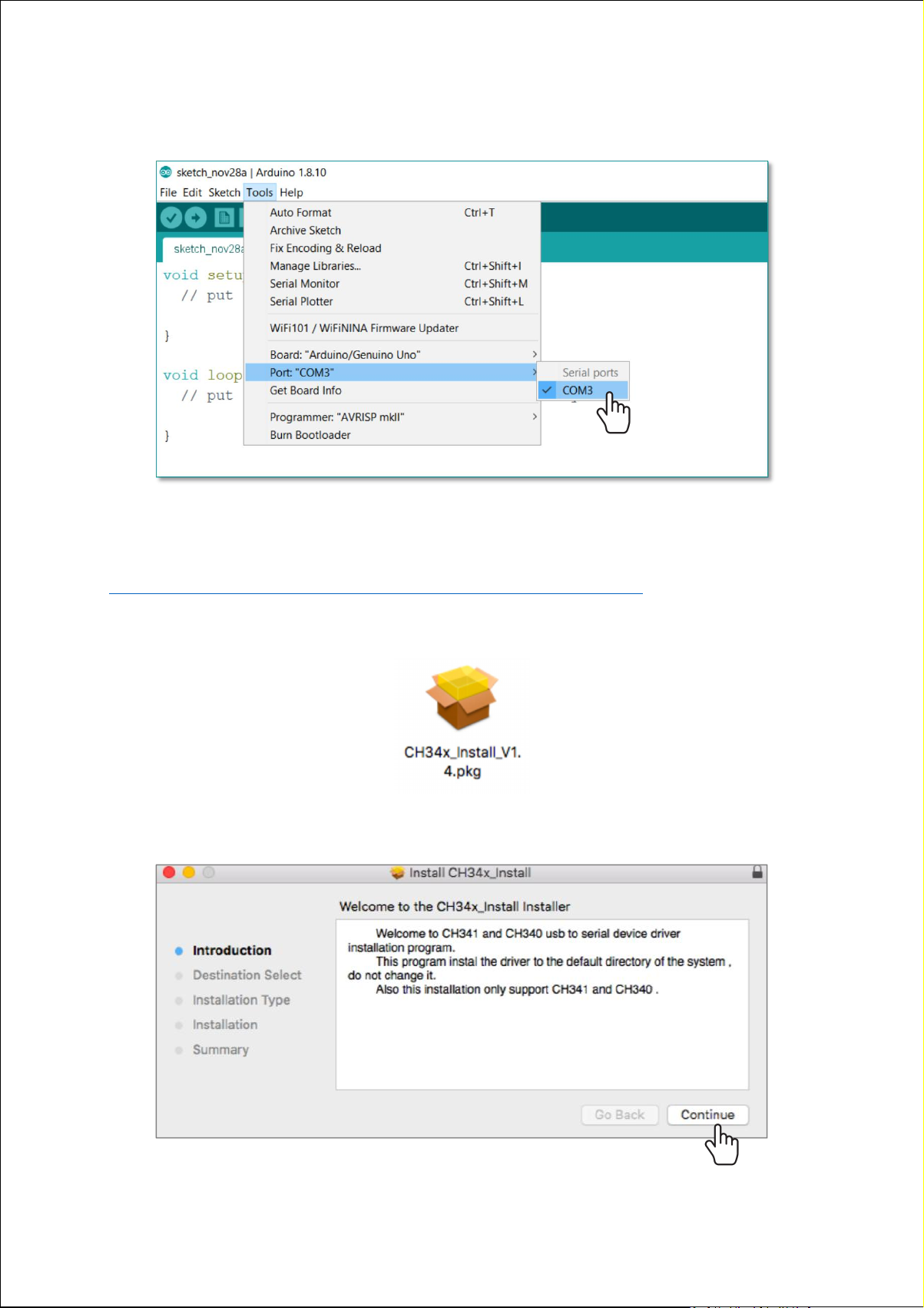
7. Launch Arduino IDE. Go to Tools > Ports > COM_ Select the right
COM port.
For Mac users:
1. Download the driver here:
https://cdn.cytron.io/makeruno/CH341SER_MAC.ZIP
2. Double click the zip file, open the unzipped folder and then double
click the pkg file.
3. Click “CONTINUE” to begin installation.
11Simplifying Digital Making
Page 12
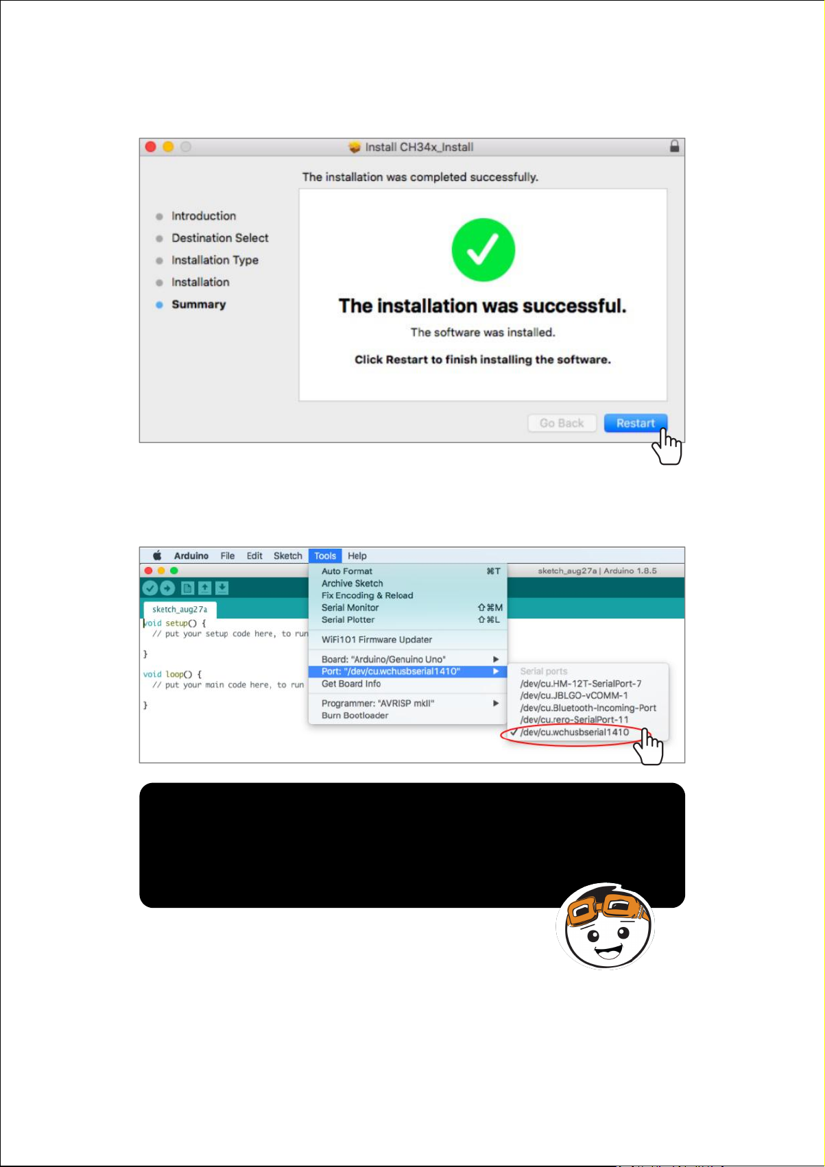
4. Once done, click “Restart”.
5. After you've restarted your Mac, launch Arduino IDE. Go to
Tools > Port > /dev/cu.wchusbserial1410
Note: If you have problems installing the driver,
please follow the troubleshooting steps here:
https://cdn.cytron.io/makeruno/Troubleshooting_
CH431_Driver_For_Mac.pdf
12Simplifying Digital Making
Page 13

LESSON 1
DIGITAL OUTPUT
Page 14
Project 1: Turn On An LED
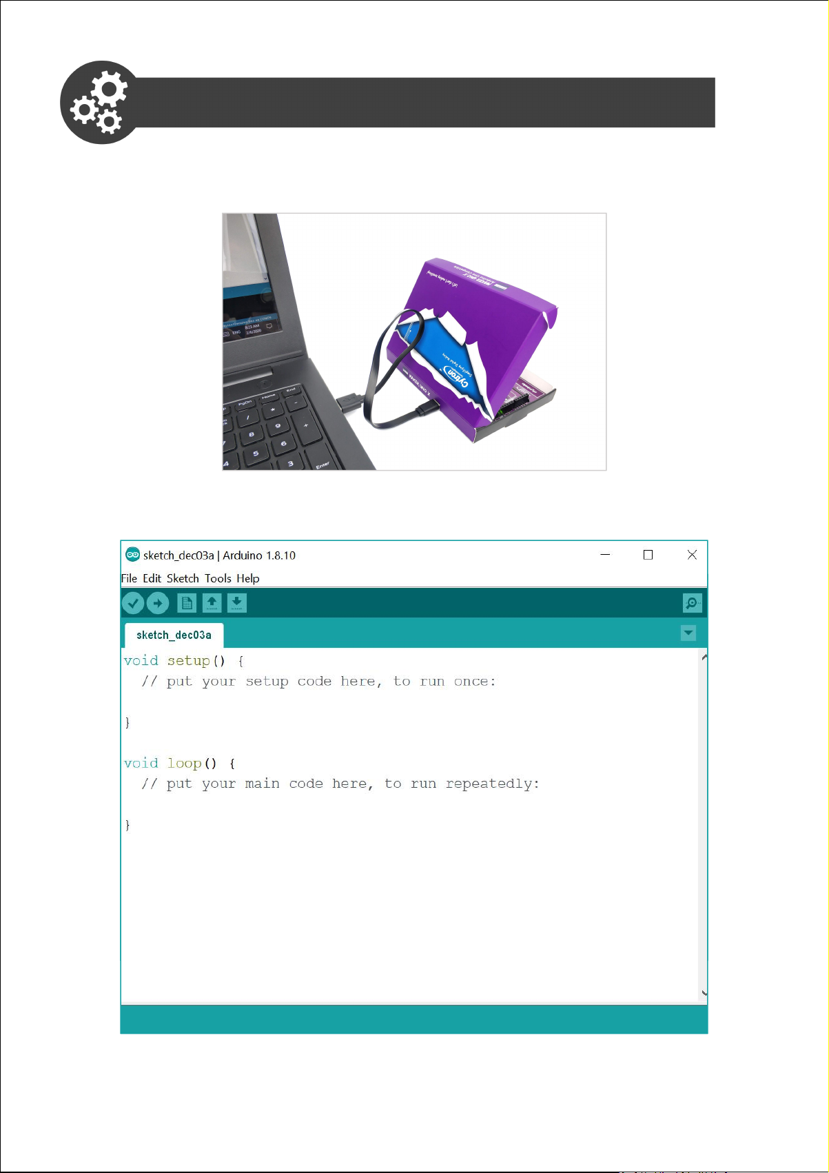
1. Connect your Maker UNO X to your PC with a micro USB cable.
2. Launch Arduino IDE and you will see the following new sketch.
Project_1
void setup() {
// put your setup code here, to run once:
pinMode(7,OUTPUT);
}
void loop() {
// put your main code here, to run repeatedly:
digitalWrite(7,HIGH);
}
14Simplifying Digital Making
Page 15
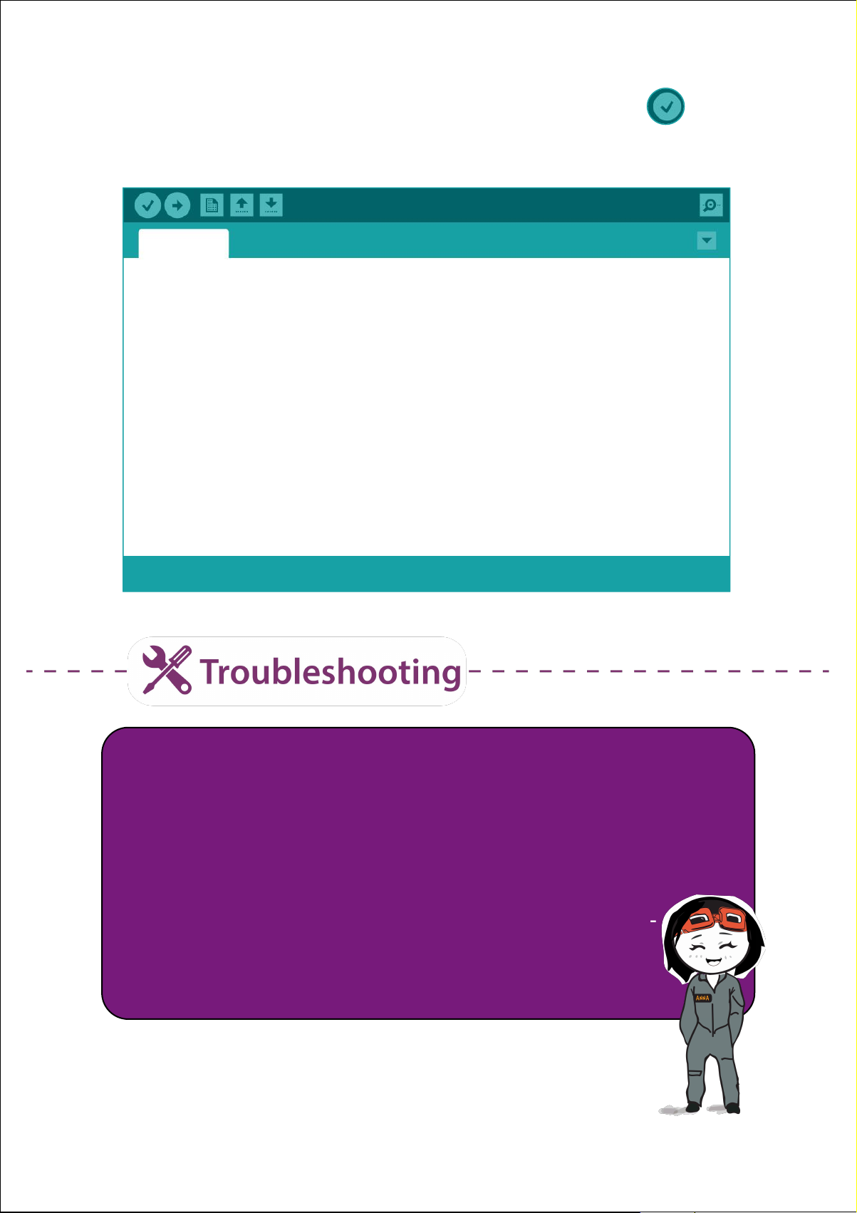
3. Write this code into your sketch and then click this button to
compile your code. Wait for a few seconds until you see “Done
Compiling” appear at the bottom of the sketch.
Project_1
void setup() {
// put your setup code here, to run once:
pinMode(7, OUTPUT);
}
void loop() {
// put your main code here, to run repeatedly:
digitalWrite(7, HIGH);
}
Done compiling.
If error occurs, check and correct your code line by line, and then
compile again.
ü Arduino is case sensitive - make sure you use uppercase for
OUTPUT and camel case for pinMode and digitalWrite (i.e. use
capital letters for M and W).
ü Check to make sure you have not missed out any signs -
; , ( ) and { } .
ü Do not mix up normal brackets ( ) with curly braces { } .
15Simplifying Digital Making
Page 16
4. Next, click button to upload. Uploading will start immediately.
Once completed, you will see “Done Uploading” appear at the
bottom of the sketch.
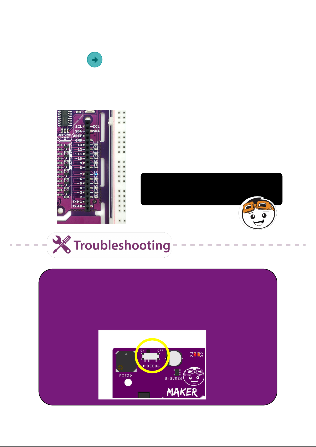
5. Slide the switch to turn on the “Debug” mode. Check your result.
You can see that LED 7 is lighted up
while the rest of the LEDs are off.
1. If error occurs while uploading, please ensure that your Maker
UNO X is connected to your PC and the correct port is selected
(Tools > Port > COM_ ).
2. Remember to turn on the “Debug” mode to enable the built-in
LEDs on Maker UNO X.
16Simplifying Digital Making
Page 17
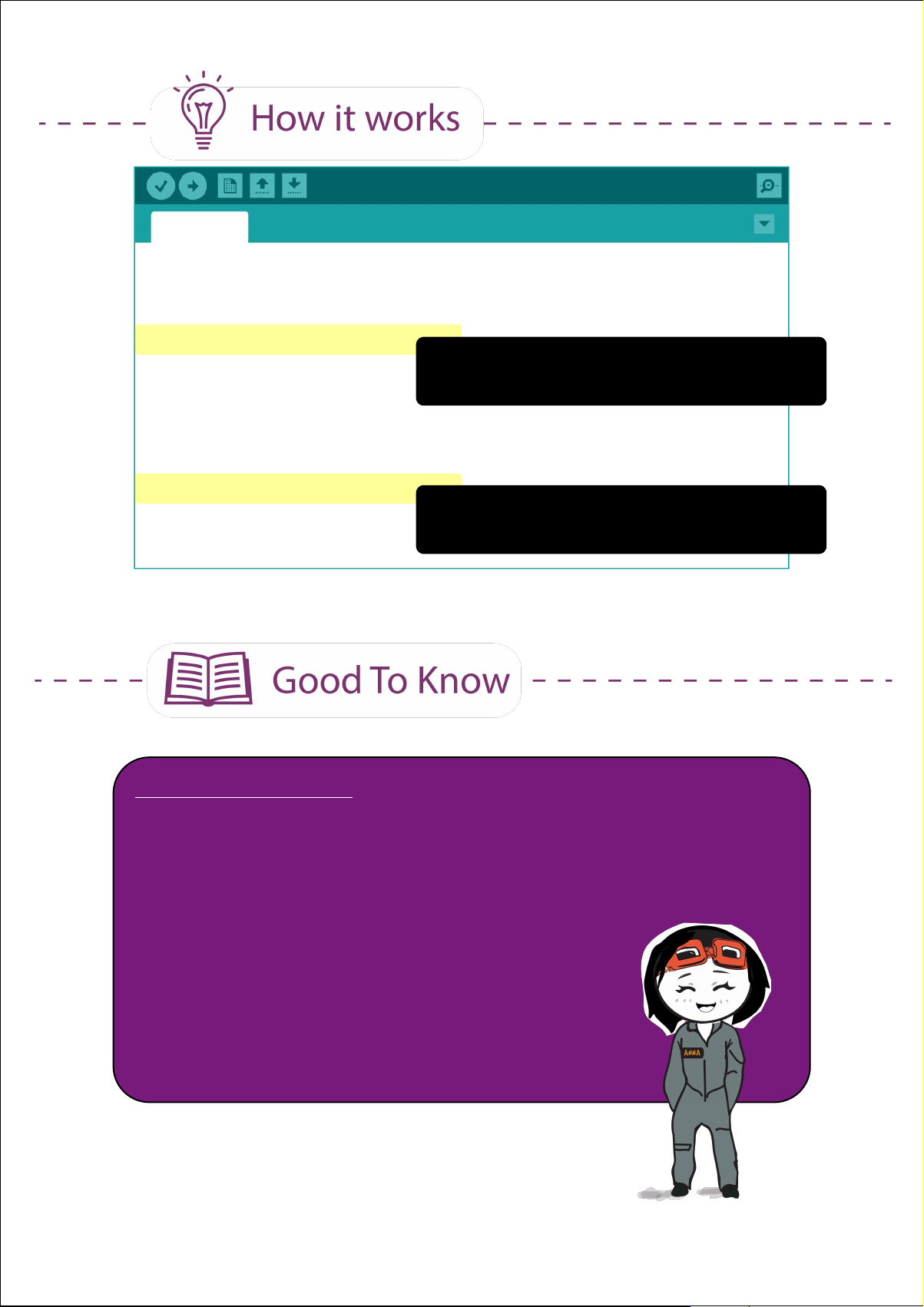
Project_1
void setup() {
// put your setup code here, to run once:
pinMode(7, OUTPUT);
This line tells the board to set pin 7 as
}
output.
void loop() {
// put your main code here, to run repeatedly:
digitalWrite(7, HIGH);
}
ARDUINO FUNCTION
This line tells the board to set pin 7 to
HIGH (i.e. to turn on).
1. To set a pin as input or output:
pinMode (pin, mode)
pin: the number of the pin you are setting
mode: INPUT, OUTPUT, or INPUT_PULLUP
2. To set a digital pin to HIGH (on) or LOW (off)
digitalWrite(pin, value)
pin: the number of the pin you are setting
value: HIGH or LOW
17Simplifying Digital Making
Page 18
Project 2: Blink An LED
1. Modify your code in Project 1 to the following:
Project_2
void setup() {
// put your setup code here, to run once:
pinMode(7, OUTPUT);
}
void loop() {
// put your main code here, to run repeatedly:
digitalWrite(7, HIGH);
delay (100);
digitalWrite(7, LOW);
delay (100);
}
2. Compile and upload your code to your Maker UNO X.
3. Check your result.
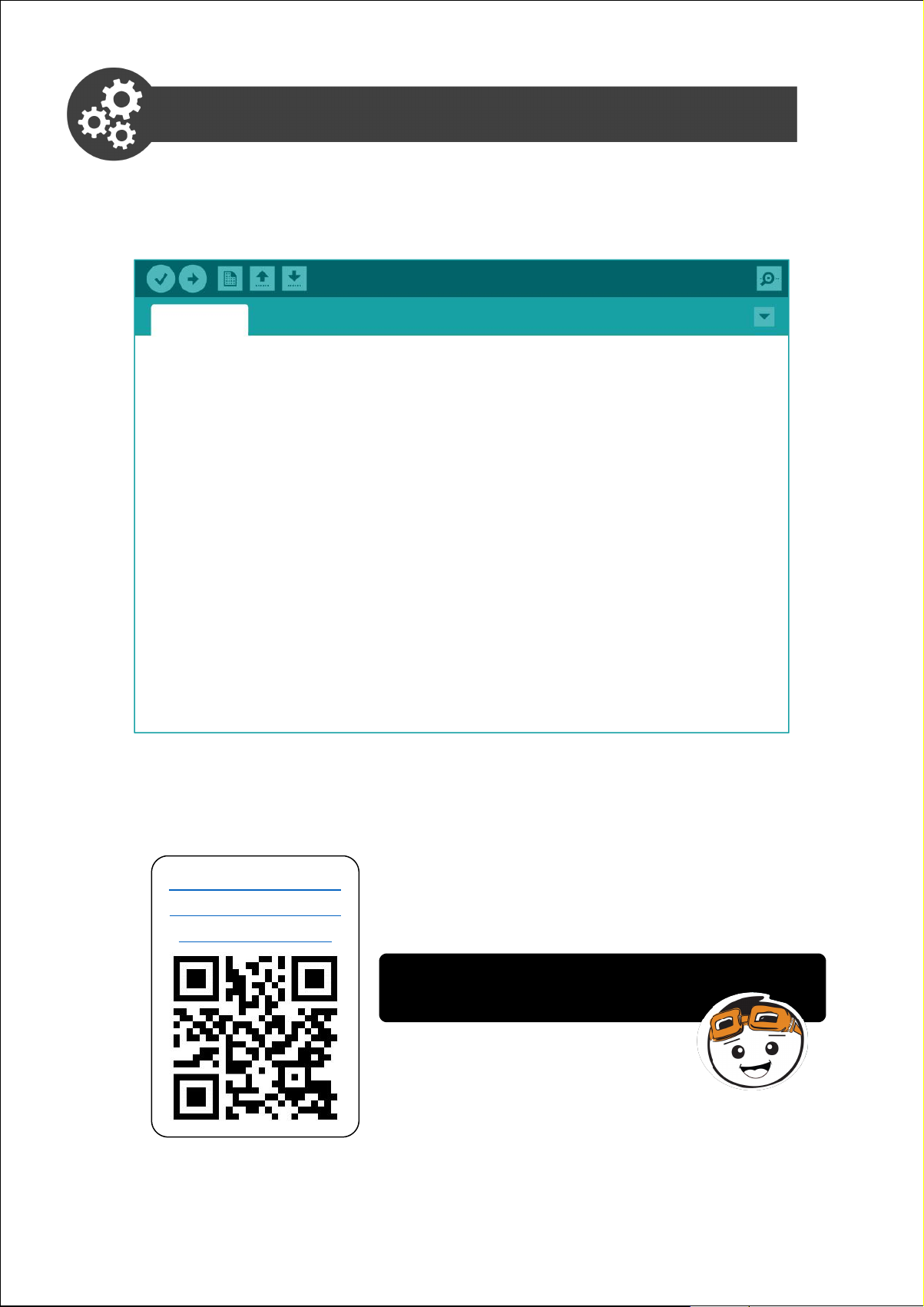
Click here or scan
QR code to watch
the demo video.
LED 7 will be blinking continually while the
rest of the LEDs are off.
18Simplifying Digital Making
Page 19
4. Change the delay value to 1000 and then upload to your board again.
Project_2
void setup() {
// put your setup code here, to run once:
pinMode(7, OUTPUT);
}
void loop() {
// put your main code here, to run repeatedly:
digitalWrite(7, HIGH);
delay (1000);
digitalWrite(7, LOW);
delay (1000);
}
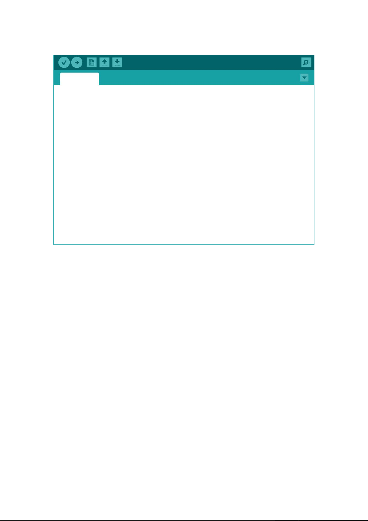
5. Observe the result and compare with the previous program. Can you
tell the difference?
19Simplifying Digital Making
Page 20
Project_2
void setup() {
// put your setup code here, to run once:
pinMode(7, OUTPUT);
}
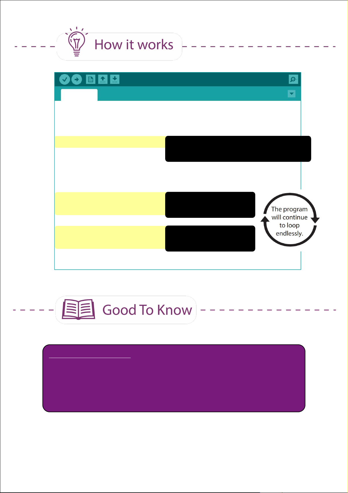
This line tells the board to set pin 7
as output.
void loop() {
// put your main code here, to run repeatedly:
digitalWrite(7, HIGH);
delay (1000);
digitalWrite(7, LOW);
delay (1000);
Turn on LED 7
Hold for 1000ms
Turn off LED 7
Hold for 1000ms
}
ARDUINO FUNCTION
1. To hold or pause the program
delay(ms)
ms: the number of milliseconds to pause
20Simplifying Digital Making
Page 21
Project 3: Blink the LEDs in Sequence
In this project, we want to blink LED 2, LED 3, LED 4, LED 5, LED 6 and
LED 7 in sequence.
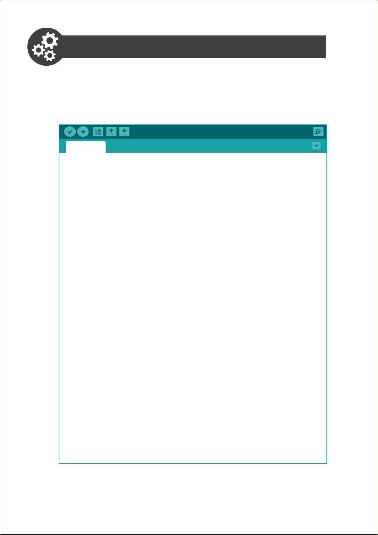
1. Modify your previous code to the following:
Project_3
void setup() {
pinMode(2, OUTPUT);
pinMode(3, OUTPUT);
pinMode(4, OUTPUT);
pinMode(5, OUTPUT);
pinMode(6, OUTPUT);
pinMode(7, OUTPUT);
}
void loop() {
digitalWrite(2, HIGH);
digitalWrite(3, HIGH);
digitalWrite(4, HIGH);
digitalWrite(5, HIGH);
digitalWrite(6, HIGH);
digitalWrite(7, HIGH);
delay (1000);
digitalWrite(2, LOW);
digitalWrite(3, LOW);
digitalWrite(4, LOW);
digitalWrite(5, LOW);
digitalWrite(6, LOW);
digitalWrite(7, LOW);
delay (1000);
}
2. Compile and upload your code to your Maker UNO X.
21Simplifying Digital Making
Page 22
3. Check your result. Is it the desired outcome?
Click here or scan
QR code to watch
the demo video.
LED 2 to LED 7 turn on and then turn
off together; which is NOT the effect
that we want. Why?
Project_3
void setup() {
pinMode(2, OUTPUT);
pinMode(3, OUTPUT);
pinMode(4, OUTPUT);
pinMode(5, OUTPUT);
pinMode(6, OUTPUT);
pinMode(7, OUTPUT);
}
void loop() {
digitalWrite(2, HIGH);
digitalWrite(3, HIGH);
digitalWrite(4, HIGH);
digitalWrite(5, HIGH);
digitalWrite(6, HIGH);
digitalWrite(7, HIGH);
delay (1000);
digitalWrite(2, LOW);
digitalWrite(3, LOW);
digitalWrite(4, LOW);
digitalWrite(5, LOW);
digitalWrite(6, LOW);
digitalWrite(7, LOW);
delay (1000);
}
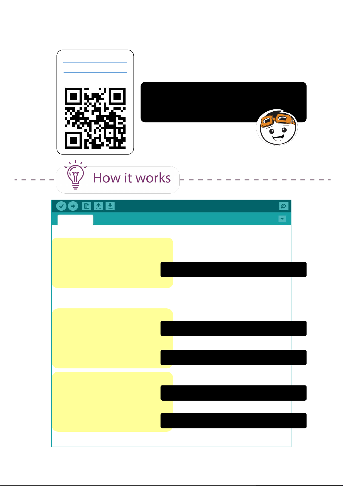
Set Pin 2 to Pin 7 as output.
Turn on LED 2 to LED 7
Hold for 1000ms.
Turn off LED 2 to LED 7
Hold for 1000ms.
22Simplifying Digital Making
Page 23
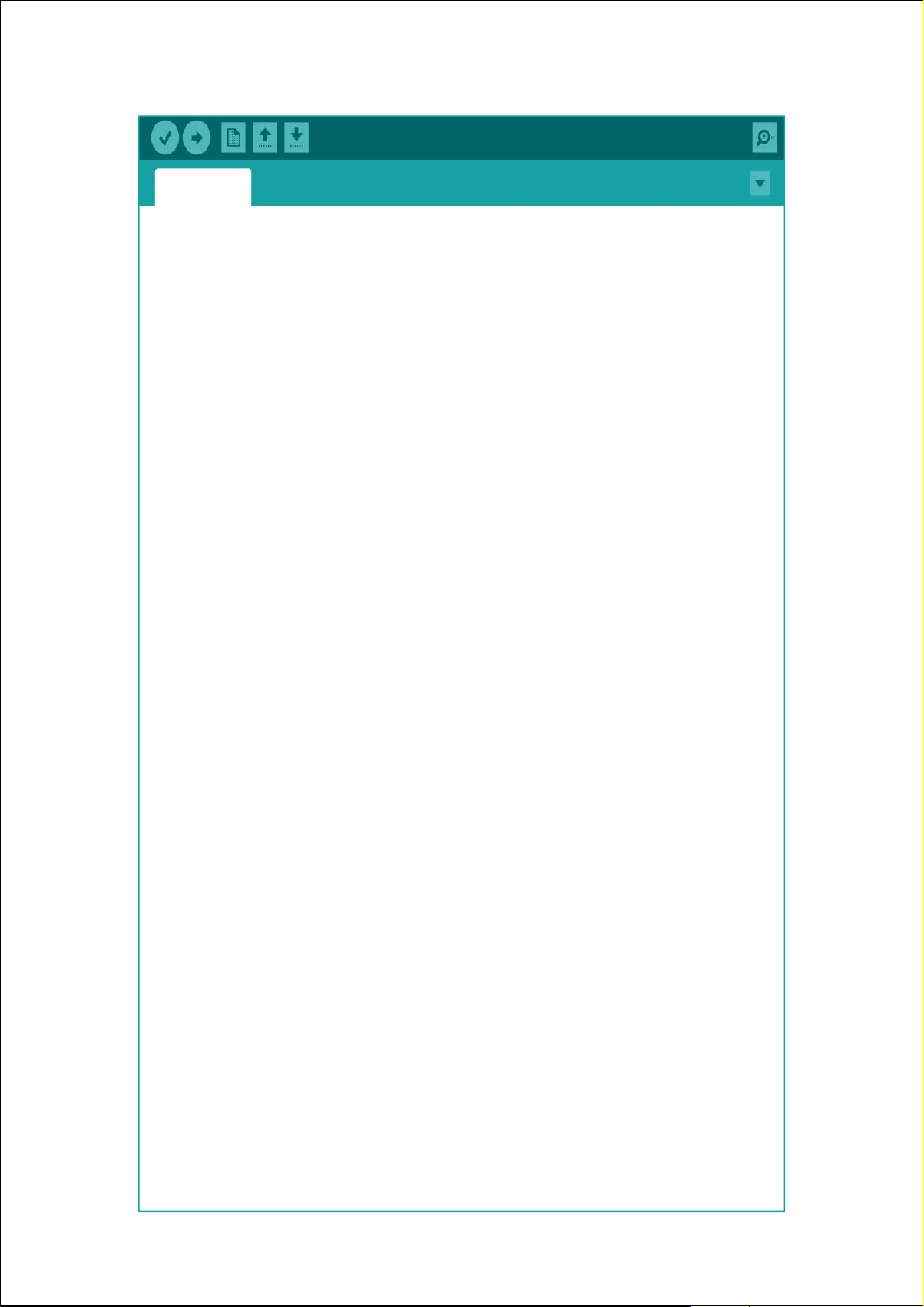
4. Modify your code to the following.
Project_3
void setup() {
pinMode(2, OUTPUT);
pinMode(3, OUTPUT);
pinMode(4, OUTPUT);
pinMode(5, OUTPUT);
pinMode(6, OUTPUT);
pinMode(7, OUTPUT);
}
void loop() {
digitalWrite(2, HIGH);
delay (1000);
digitalWrite(3, HIGH);
delay (1000);
digitalWrite(4, HIGH);
delay (1000);
digitalWrite(5, HIGH);
delay (1000);
digitalWrite(6, HIGH);
delay (1000);
digitalWrite(7, HIGH);
delay (1000);
digitalWrite(2, LOW);
delay (1000);
digitalWrite(3, LOW);
delay (1000);
digitalWrite(4, LOW);
delay (1000);
digitalWrite(5, LOW);
delay (1000);
digitalWrite(6, LOW);
delay (1000);
digitalWrite(7, LOW);
delay (1000);
}
23Simplifying Digital Making
Page 24
3. Check your result. Is it the desired outcome?
Click here or scan
QR code to watch
the demo video.
Now the LEDs will turn on one by one and
then turn off one by one.
void loop() {
digitalWrite(2, HIGH);
digitalWrite(3, HIGH);
digitalWrite(4, HIGH);
digitalWrite(5, HIGH);
digitalWrite(6, HIGH);
digitalWrite(7, HIGH);
delay (1000);
void loop() {
digitalWrite(2, HIGH);
delay (1000);
digitalWrite(3, HIGH);
delay (1000);
digitalWrite(4, HIGH);
delay (1000);
digitalWrite(5, HIGH);
delay (1000);
digitalWrite(6, HIGH);
delay (1000);
digitalWrite(7, HIGH);
delay (1000);
Although both versions of the code will turn on the LEDs, the results
are different. In Version 1, you will see as though all the LEDs light up
at the same time.This is because the lines are executed line by
line in quick succession (in less than 1 micro second).
To get the LEDs to light up one by one in sequence, we need to add
a delay after lighting up each LED (as in version 2 code).
24Simplifying Digital Making
Page 25
Task: Program LED 2 to LED 13 to execute the blinking pattern as shown
in the demo video below.
Click here or scan
QR code to watch
the demo video.
CONGRATULATIONS! You have completed Lesson 1 and learnt the
following:
1. How to set pin as digital output
2. How to set a digital output pin to HIGH and LOW
3. How to use delay function
25Simplifying Digital Making
Page 26

LESSON 2
DIGITAL INPUT
Page 27
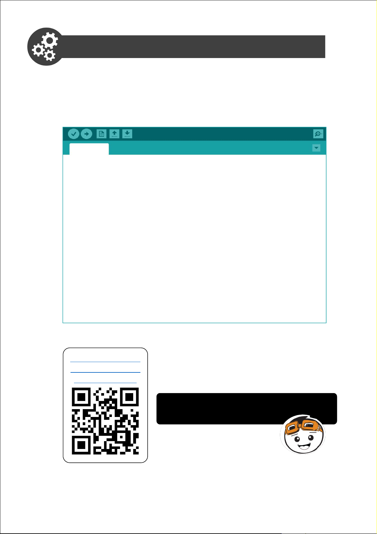
Project 4: On-Board Push Button Switch
In this project, we want to control an LED using the on-board push button
switch.
1. Open a new sketch and then write the following code.
Project_4
void setup() {
pinMode(4, OUTPUT);
pinMode(2, INPUT_PULLUP);
}
void loop() {
if (digitalRead(2) == LOW) {
digitalWrite(4, HIGH);
}
else {
digitalWrite(4, LOW);
}
}
2. Compile and upload the program. Check your result.
Click here or scan
QR code to watch
the demo video.
LED 4 will light up when the push
button is pressed.
27Simplifying Digital Making
Page 28

Project_4
void setup() {
pinMode(4, OUTPUT);
pinMode(2, INPUT_PULLUP);
}
void loop() {
if (digitalRead(2) == LOW) {
digitalWrite(4, HIGH);
}
else {
digitalWrite(4, LOW);
}
}
Set Pin 4 as output.
Set Pin 2 as on-board switch input.
Read Pin 2. If it is LOW (switch is
pressed),
set Pin 4 to HIGH (turn on LED 4).
Else (switch is not pressed),
set Pin 4 to LOW (turn off LED 4).
ARDUINO FUNCTION
1. To use the on-board push button switch, we need to set it as
internal pullup input.
pinMode(2, INPUT_PULLUP);
2. The on-board LED at Pin 2 can act as an input indicator when
you turn on Debug mode. LED 2 will be turned off whenever the
on-board switch is pressed.
3. The on-board switch is internally connected to Pin 2. Meaning it
is occupied and cannot be connected to any other external
components when it is in use.
28Simplifying Digital Making
Page 29

CODING SYNTAX
1. To use the “if-else” statement
if (condition 1) {
// do thing A
}
else if (condition 2) {
// do thing B
}
else {
// do thing C
}
2. We can use // (two adjacent slashes) to leave a reminder or
comment while programming. Anything written after this sign will
be ignored by the program and will not be executed.
// your comments here
29Simplifying Digital Making
Page 30
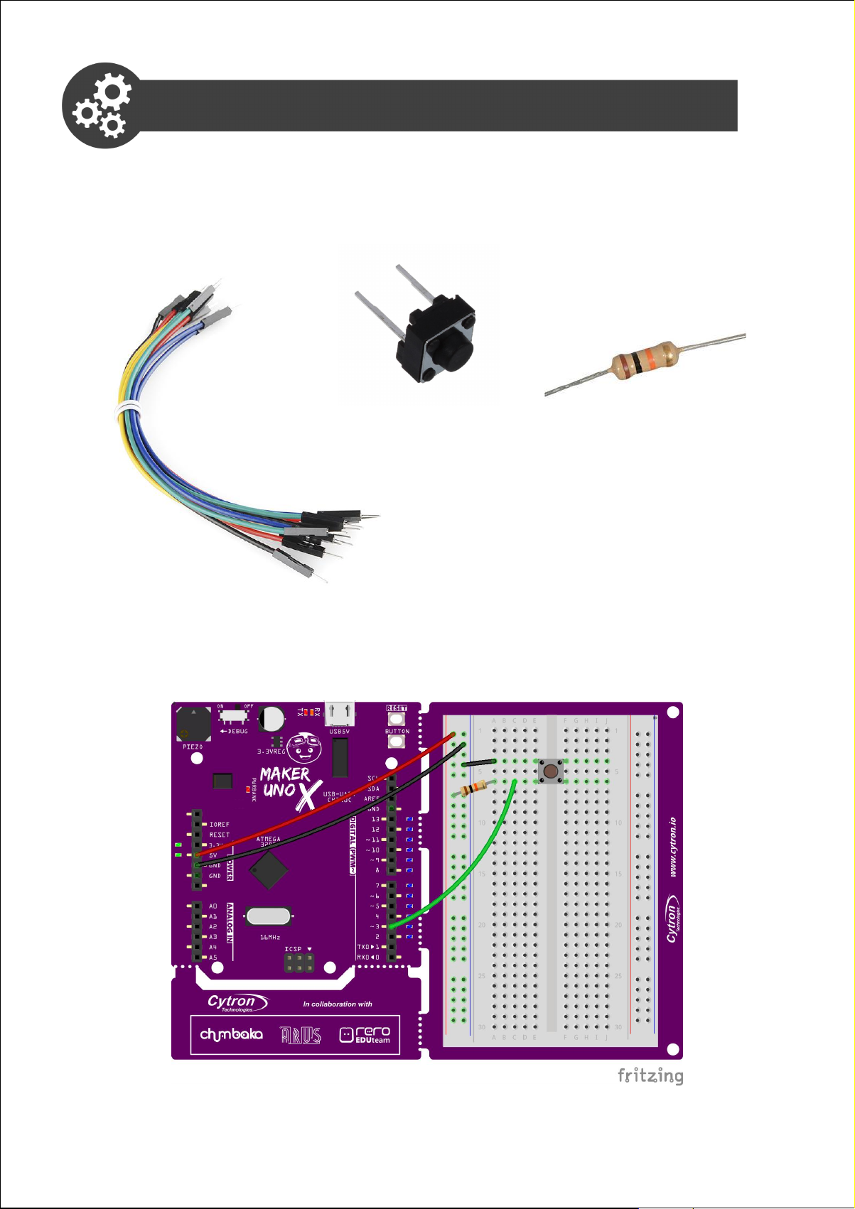
Project 5: External Push Button Switch
In this project, we want to construct a basic circuit of an external push
button switch.
1. Get these components.
Jumper wire
2. Construct the circuit as shown below.
Push button switch
10K ohm resistor
30Simplifying Digital Making
Page 31

3. Press the external push button switch. Observe LED 3 whether it is
on before you press the switch and goes off when the switch is
pressed. If it is not working, please fix your circuit before you proceed
to the next step.
4. Modify your Project 4 code to the following, and then upload to your
Maker UNO X.
Project_5
void setup() {
pinMode(4, OUTPUT);
pinMode(3, INPUT);
}
void loop() {
if (digitalRead(3) == LOW) {
digitalWrite(4, HIGH);
}
else {
digitalWrite(4, LOW);
}
}
31Simplifying Digital Making
Page 32
3. Check your result.
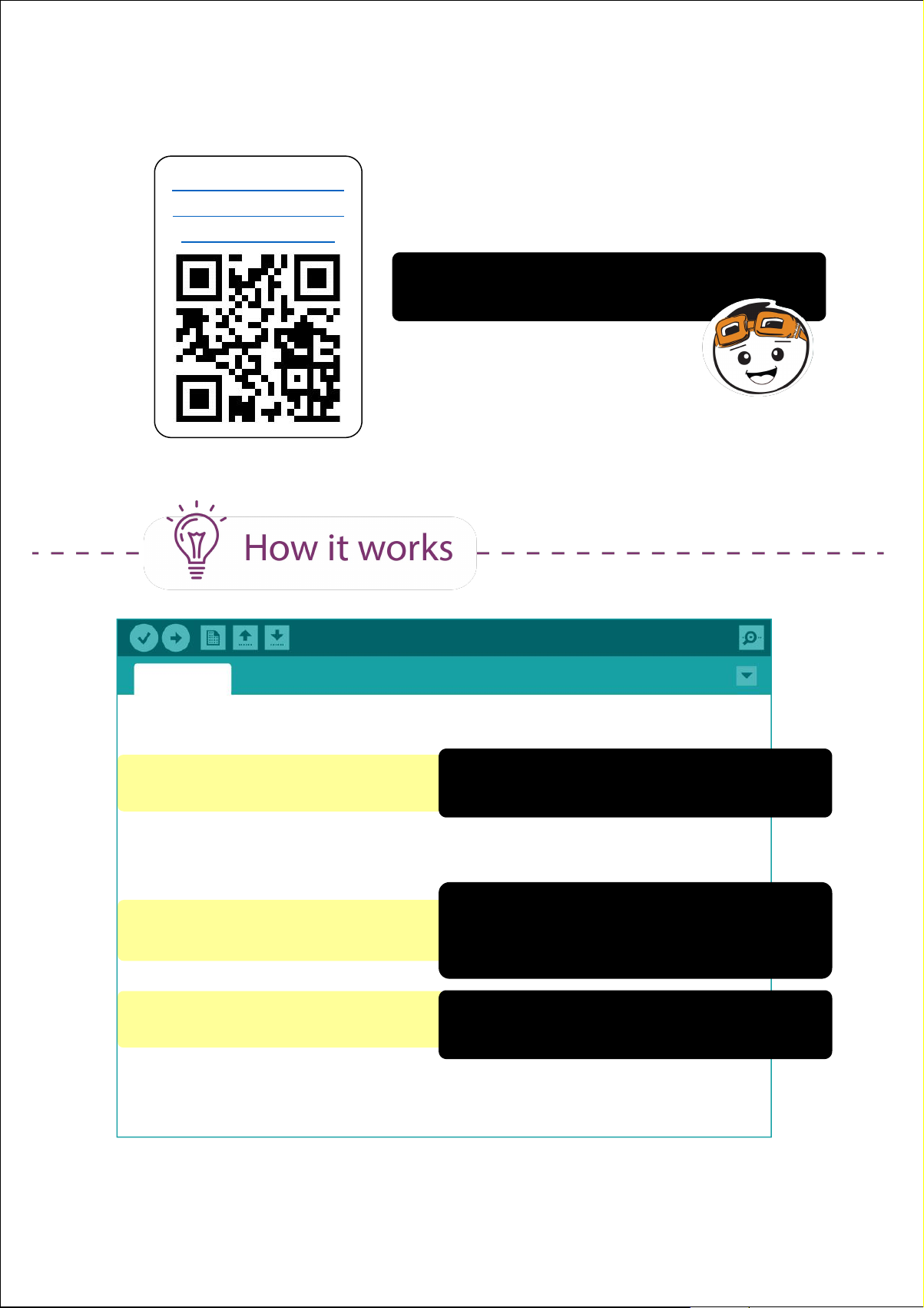
Click here or scan
QR code to watch
the demo video.
When the external push button switch is
pressed, LED 4 will turn on.
Project_5
void setup() {
pinMode(4, OUTPUT);
pinMode(3, INPUT);
}
void loop() {
if (digitalRead(3) == LOW) {
digitalWrite(4, HIGH);
}
else {
digitalWrite(4, LOW);
}
}
Set Pin 4 as output.
Set Pin 3 as input.
Read Pin 3. If it is LOW (switch is
pressed),
set Pin 4 to HIGH (turn on LED 4).
Else (switch is not pressed),
set Pin 4 to LOW (turn off LED 4).
32Simplifying Digital Making
Page 33

ARDUINO FUNCTION
1. Switch is an input device; you need to set that pin as input before
you can use it.
pinMode(pin, INPUT);
BASIC ELECTRONICS
1. Breadboard's internal connectivity.
2. For any digital input, you can make it as a “pull-up” or “pull-down”
circuit.
VS
It is HIGH when the
switch is not pressed.
It is LOW when the
switch is not pressed.
In this project, we used “pull-up” circuit. You can choose to use
either type of circuit for your future projects but remember to
change the code accordingly.
33Simplifying Digital Making
Page 34
Task: Use both on-board and external switches. When both switches are
not pressed, both LED 4 and LED 5 will be on. If the on-board switch is
pressed, LED 4 goes off. If external switch is pressed, LED 5 goes off.
Click here or scan
QR code to watch
the demo video.
CONGRATULATIONS! You have completed Lesson 2 and learnt the
following:
1. How to read digital input signal.
2. How to control an LED using a switch.
3. How to construct a simple pull-up / pull-down
circuit.
4. How to use if-else statement.
34Simplifying Digital Making
Page 35

LESSON 3
ANALOG OUTPUT
Page 36
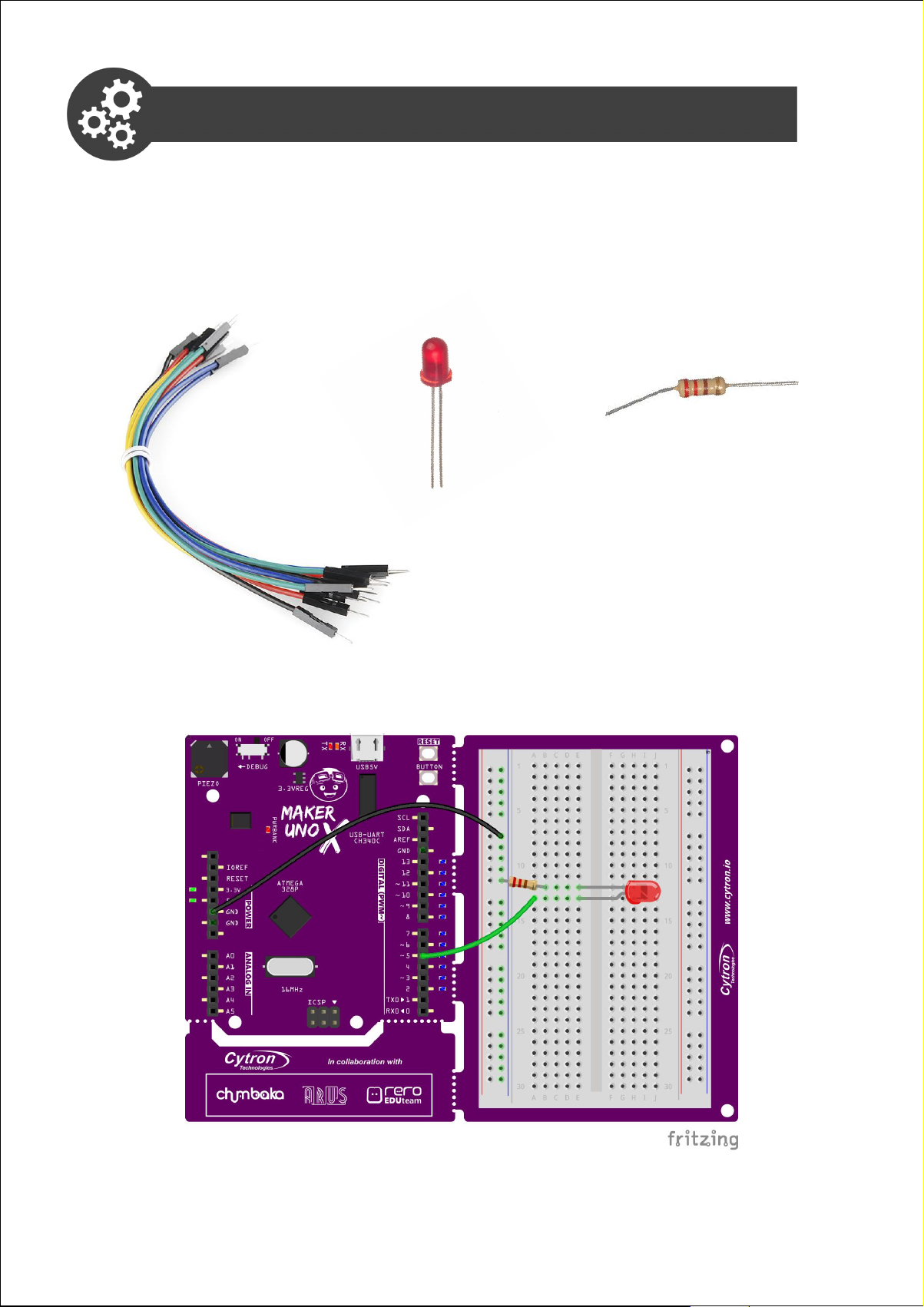
Project 6: Construct an LED Circuit
In this project, we are going to construct a simple circuit with one LED.
1. Get these components.
Jumper wire LED 220 ohm resistor
2. Construct the circuit as shown below.
36Simplifying Digital Making
Page 37
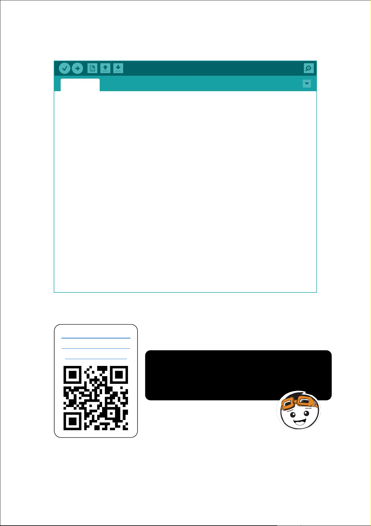
3. Write and upload the following code to your board.
Project_6
void setup() {
pinMode(2, INPUT_PULLUP);
pinMode(5, OUTPUT);
}
void loop() {
if (digitalRead(2) == LOW)
while (1) {
digitalWrite(5, HIGH);
delay(200);
digitalWrite(5, LOW);
delay(200);
}
else digitalWrite(5, LOW);
}
4. Check your result.
Click here or scan
QR code to watch
the demo video.
Both on-board LED and the external LED at
Pin 5 will blink after the on-board switch is
pressed. LED 5 will not stop blinking unless
the reset button is pressed.
37Simplifying Digital Making
Page 38
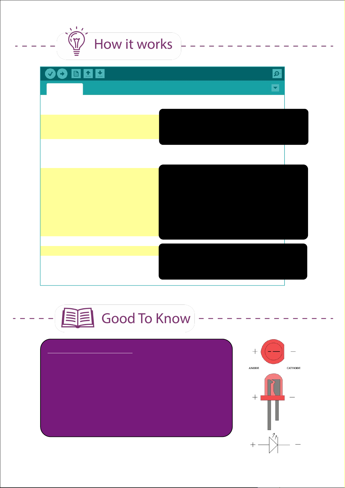
Project_6
void setup() {
pinMode(2, INPUT_PULLUP);
pinMode(5, OUTPUT);
}
void loop() {
if (digitalRead(2) == LOW)
while (1){
digitalWrite(5, HIGH);
delay(200);
digitalWrite(5, LOW);
delay(200);
}
else digitalWrite(5, LOW);
}
Set Pin 2 as pull-up input switch.
Set Pin 5 (connected to external LED)
as output.
Read Pin 2. If it is LOW (switch is
pressed), set Pin 5 to HIGH for 200ms
and then LOW for 200ms.
*Once Pin 2 is pressed, the LED will
blink continually and it will not stop
unless the reset button is pressed.
Else if switch is not pressed, set Pin 5
to LOW (LED connected to Pin 5 will
not light up).
BASIC ELECTRONICS
1. Light emitting diode (LED) has 2 legs. You
need to connect the longer leg to the + terminal
and the shorter leg (flat edge on the casing) to
the - terminal.
An LED is polarised. It must be connected in the
right direction; otherwise, it will not work.
38Simplifying Digital Making
Page 39
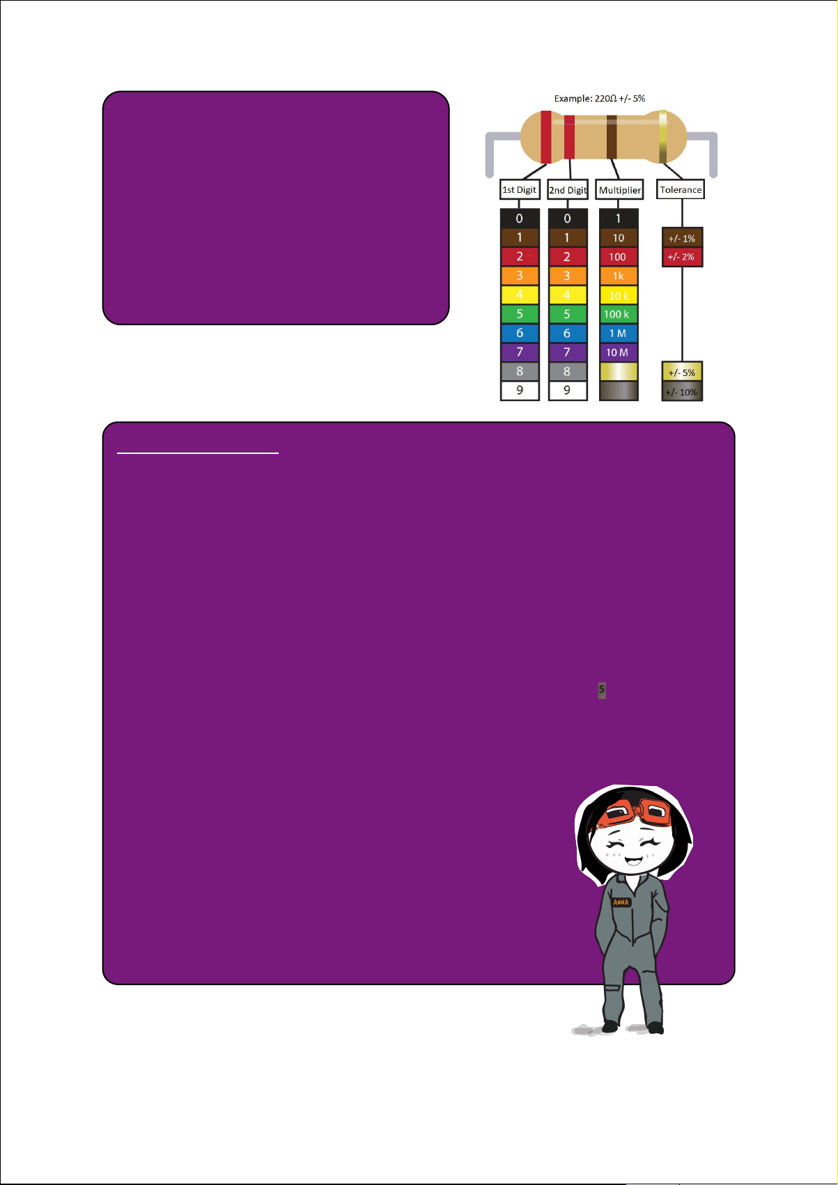
2. A resistor is not polarised, thus
you can connect the pins in any
direction.
3. The colour bands on a resistor
tell us its value. You can refer to
this chart to understand how to
read the value.
CODING SYNTAX
A while loop will loop continuously, and infinitely, until the expression
inside the parenthesis () becomes false.
while (condition)
{
// do something
}
Example:
1. Do something for 200 times.
var = 0;
while (var < 200)
{
// do something
var++;
}
2. Do something endlessly.
while (1)
{
// do something
}
39Simplifying Digital Making
Page 40
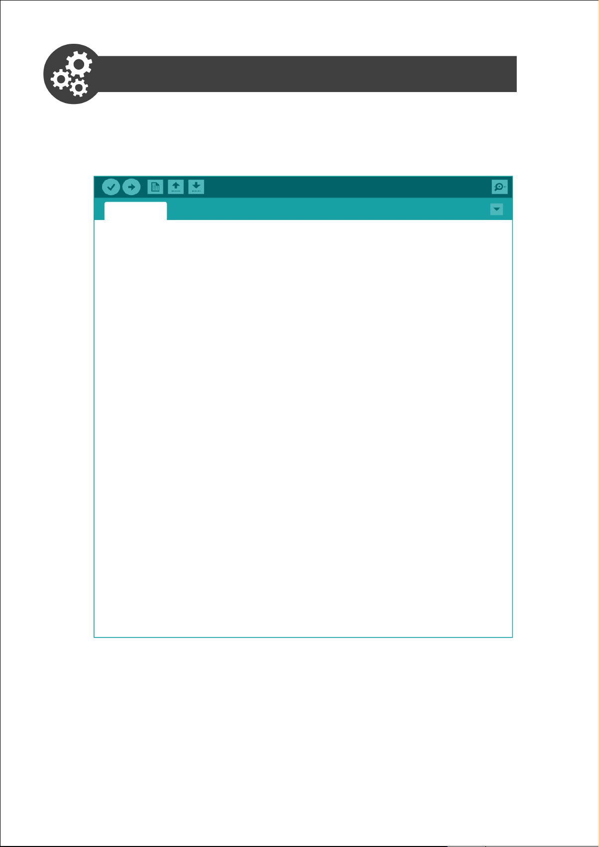
Project 7: Fade An LED
1. Using the same circuit as Project 6, write and upload the following
code to your board.
Project_7
void setup() {
pinMode(5, OUTPUT);
}
void loop() {
analogWrite(5, 60);
delay (200);
analogWrite(5, 50);
delay (200);
analogWrite(5, 40);
delay (200);
analogWrite(5, 30);
delay (200);
analogWrite(5, 20);
delay (200);
analogWrite(5, 10);
delay (200);
analogWrite(5, 0);
delay (1000);
}
40Simplifying Digital Making
Page 41

2. Check your result.
Click here or scan
QR code to watch
the demo video.
You will notice that the LED lights up and
then the brightness diminishes gradually
until they are completely off. This cycle
keeps repeating until you turn off the
power.
Project_7
void setup() {
pinMode(5, OUTPUT);
}
void loop() {
analogWrite(5, 60);
delay (200);
analogWrite(5, 50);
delay (200);
analogWrite(5, 40);
delay (200);
analogWrite(5, 30);
delay (200);
analogWrite(5, 20);
delay (200);
Set Pin 5 (connected to external LED) as
output.
Light up LED at brightness 60 for 200ms.
Light up LED at brightness 50 for 200ms.
Light up LED at brightness 40 for 200ms.
Light up LED at brightness 30 for 200ms.
Light up LED at brightness 20 for 200ms.
analogWrite(5, 10);
delay (200);
analogWrite(5, 0);
delay (1000);
}
Light up LED at brightness 10 for 200ms.
Turn off LED (brightness = 0) for 1s..
Simplifying Digital Making
41
Page 42

3. There is an easier way to achieve the same result. Modify your code
to the following and then upload to your board.
Project_7a
int brightness = 60
void setup() {
pinMode(5, OUTPUT);
}
void loop() {
analogWrite(5, brightness);
delay (200);
if (brightness == 0) {
delay (1000);
brightness = 60;
}
else {
brightness = brightness-10;
}
}
4. Check your result.
Click here or scan
QR code to watch
the demo video.
Do you get the same result as earlier?
42Simplifying Digital Making
Page 43
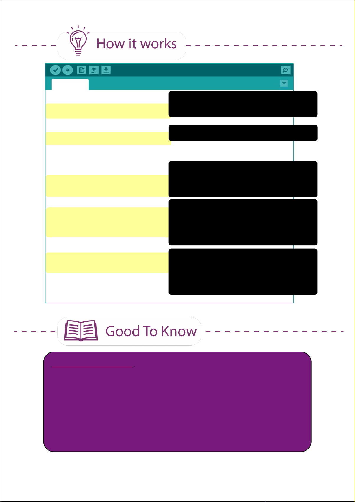
Project_7a
int brightness = 60
Define a variable (brightness) and
assign an initial value of 60 to it.
void setup() {
pinMode(5, OUTPUT);
}
void loop() {
analogWrite(5, brightness);
delay (200);
if (brightness == 0) {
delay (1000);
brightness = 60;
}
else {
brightness = brightness-10;
}
}
Set Pin 5 (external LED) as output.
Light up LED at the current value
assigned to the variable 'brightness'.
Hold for 200ms.
Check if the variable 'brightness' is
equals to 0 (LED is turned off), then
wait for 1000ms and then reassign
'brightness' value to 60.
Else if brightness value is not 0, then
update the variable 'brightness' value
to current value minus 10 (dim the
brightness of the LED).
ARDUINO FUNCTION
1. There are 2 types of outputs - digital and analog. A digital output
has only two possible values, either 0 (LOW) or 1 (HIGH). The
value for analog output can range from 0 to 255. You can use
the following function to control the analog output:
analogWrite (pin, value);
43Simplifying Digital Making
Page 44
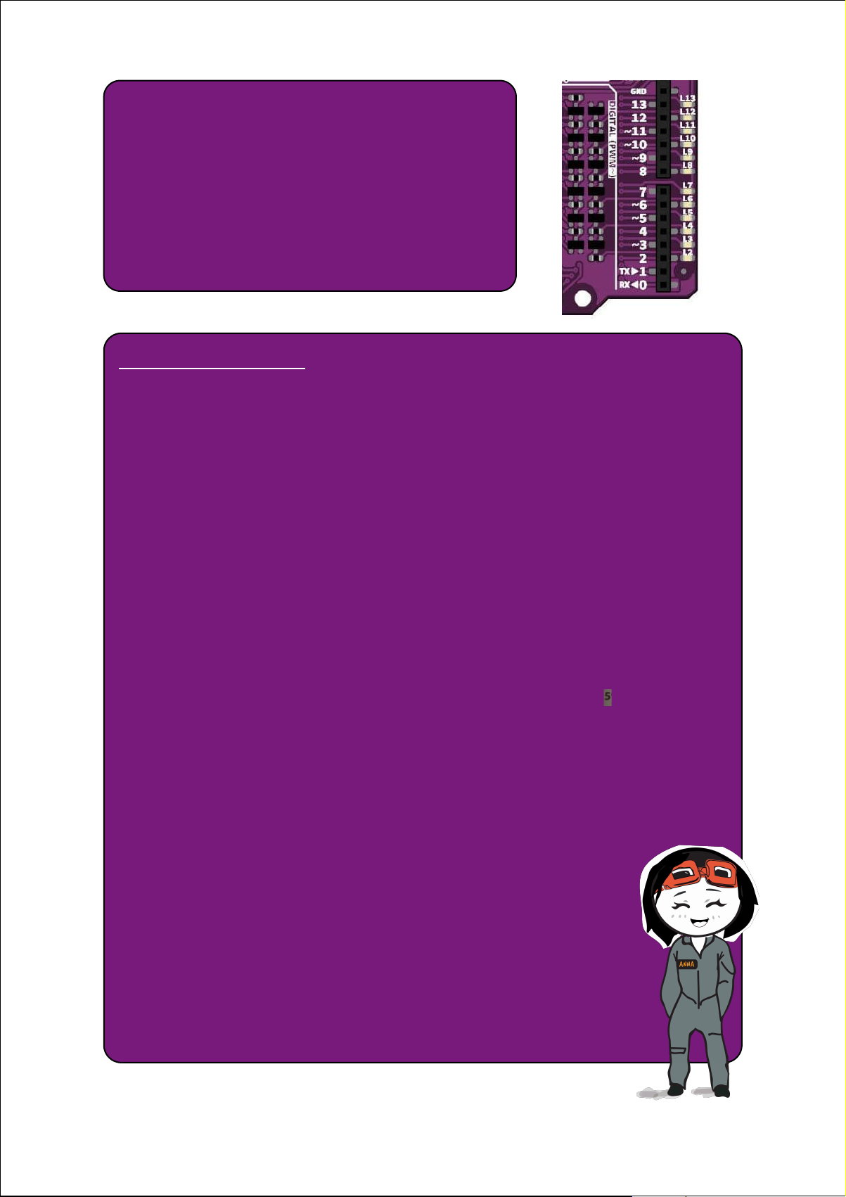
2. However, not every pin on the board
can be used for analog output. Only pins
3, 5, 6, 9, 10 and 11 (indicated with the ~
sign) have analog output functionality.
CODING SYNTAX
1. The beauty of coding is allowing the programmer to
simplify a very long instruction into a few lines of code
that execute the same task.
2. Reducing the number of lines also helps to reduce the
processing time, thus it is very important to always
optimize your code.
3. In this project, we want to reduce the LED brightness
every 200ms. So we define it as an integer variable at
the beginning of the program. “Brightness” is just a
variable name; you can choose to name it anything you
like.
4. The following are comparison commands that you can
use in your code.
x == y (x is equal to y)
x != y (x is not equal to y)
x < y (x is less than y)
x > y ( x is greater than y)
x <= y (x is less than or equal to y)
x >= y (x is greater than or equal to y)
44Simplifying Digital Making
Page 45
Task: Fade LED 5 only when the on-board switch is pressed.
Click here or scan
QR code to watch
the demo video.
CONGRATULATIONS! You have completed Lesson 3 and learnt the
following:
1. How to construct a basic LED circuit.
2. How to use while loop.
3. The difference between digital output and analog
output.
4. The importance of reducing the number of
lines of code.
45Simplifying Digital Making
Page 46

LESSON 4
MELODY TONE
Page 47
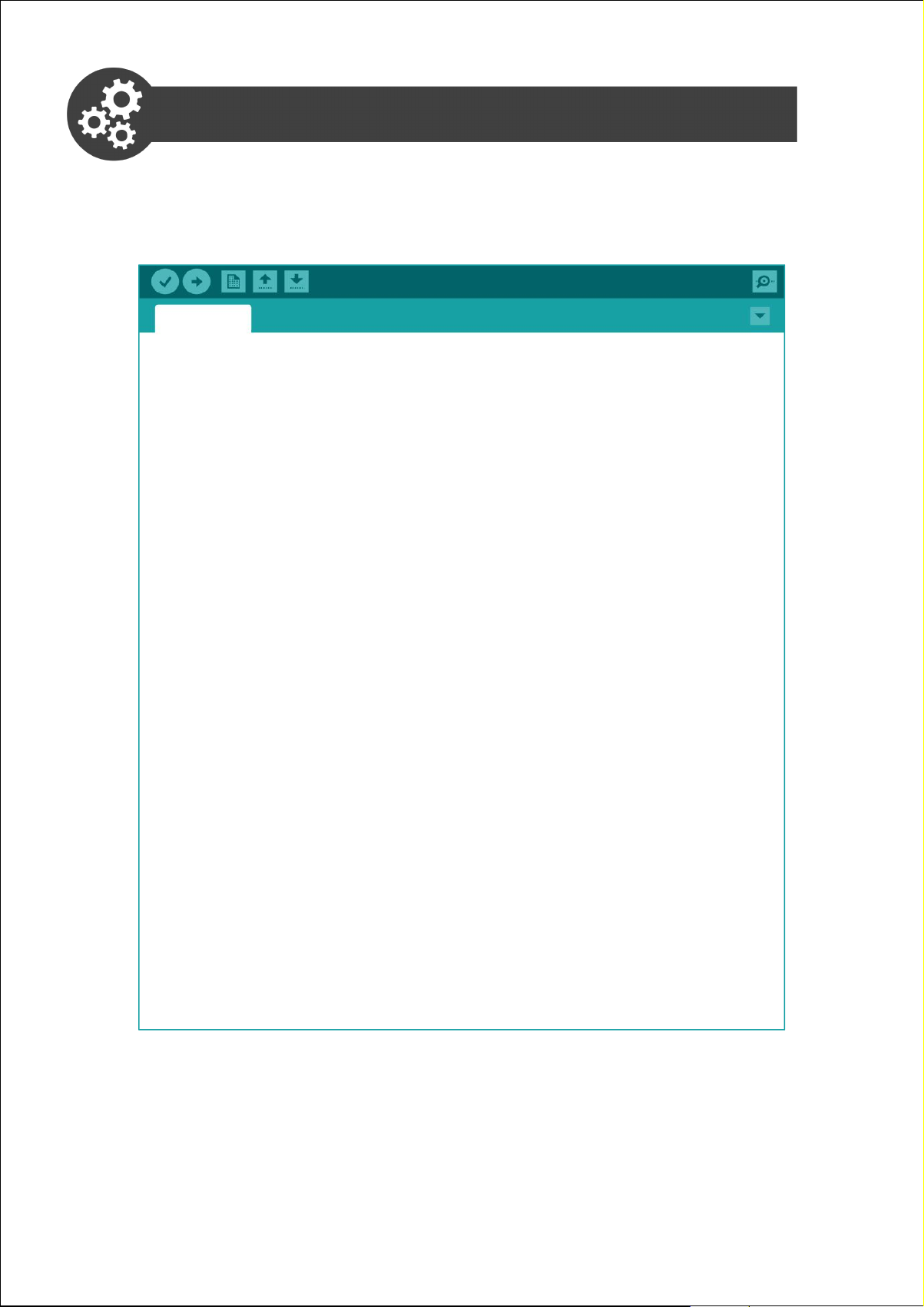
Project 8: Compose Basic Tones
1. Open a new sketch, write the following code and then upload to your
board.
Project_8
void setup() {
pinMode(8, OUTPUT);
}
void loop() {
tone (8, 262, 250);
delay (325);
tone (8, 294, 250);
delay (325);
tone (8, 330, 250);
delay (325);
tone (8, 349, 250);
delay (325);
tone (8, 392, 250);
delay (325);
tone (8, 440, 250);
delay (325);
tone (8, 494, 250);
delay (325);
tone (8, 523, 250);
delay (1000);
}
47Simplifying Digital Making
Page 48
2. Check your result.
Click here or scan
QR code to watch
the demo video.
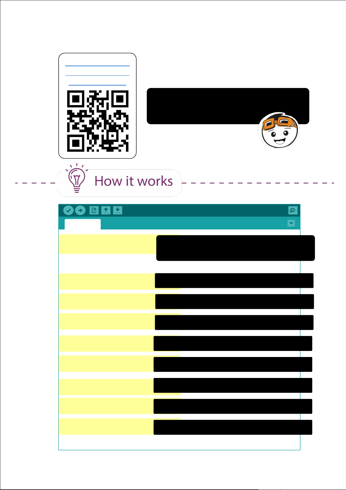
The buzzer will keep playing the basic
tones “Do Re Mi Fa So La Ti Do”
repetitively.
Project_8
void setup() {
pinMode(8, OUTPUT);
}
void loop() {
tone (8, 262, 250);
delay (325);
tone (8, 294, 250);
delay (325);
tone (8, 330, 250);
delay (325);
tone (8, 349, 250);
delay (325);
tone (8, 392, 250);
delay (325);
tone (8, 440, 250);
delay (325);
Set Pin 8 (connected to on-board piezo
buzzer) as output.
Play tone “Do” 262Hz for 250ms.
Play tone “Re” 294Hz for 250ms.
Play tone “Me” 330for 250ms.
Play tone “Fa” 392Hz for 250ms.
Play tone “So” 392Hz for 250ms.
Play tone “La” 440Hz for 250ms.
tone (8, 494, 250);
delay (325);
tone (8, 523, 250);
delay (1000);
}
Play tone “Ti” 494Hz for 250ms.
Play tone “High Do” 523Hz for 1000ms.
48Simplifying Digital Making
Page 49
ARDUINO FUNCTION
1. To get the piezo buzzer to play a tone.
tone (pin, frequency, duration);
pin: the pin that is connected to the piezo buzzer
frequency: frequency of the note in hertz (Hz)
duration: the duration of the note in milliseconds (ms)
2. To distinguish the different notes in a melody, we need to add a
delay between the notes. The delay has to drag 30% longer
than the note duration to fully play out the note. For example, if
the note duration is 250ms, we should add a delay of 325ms
(250ms + 75ms).
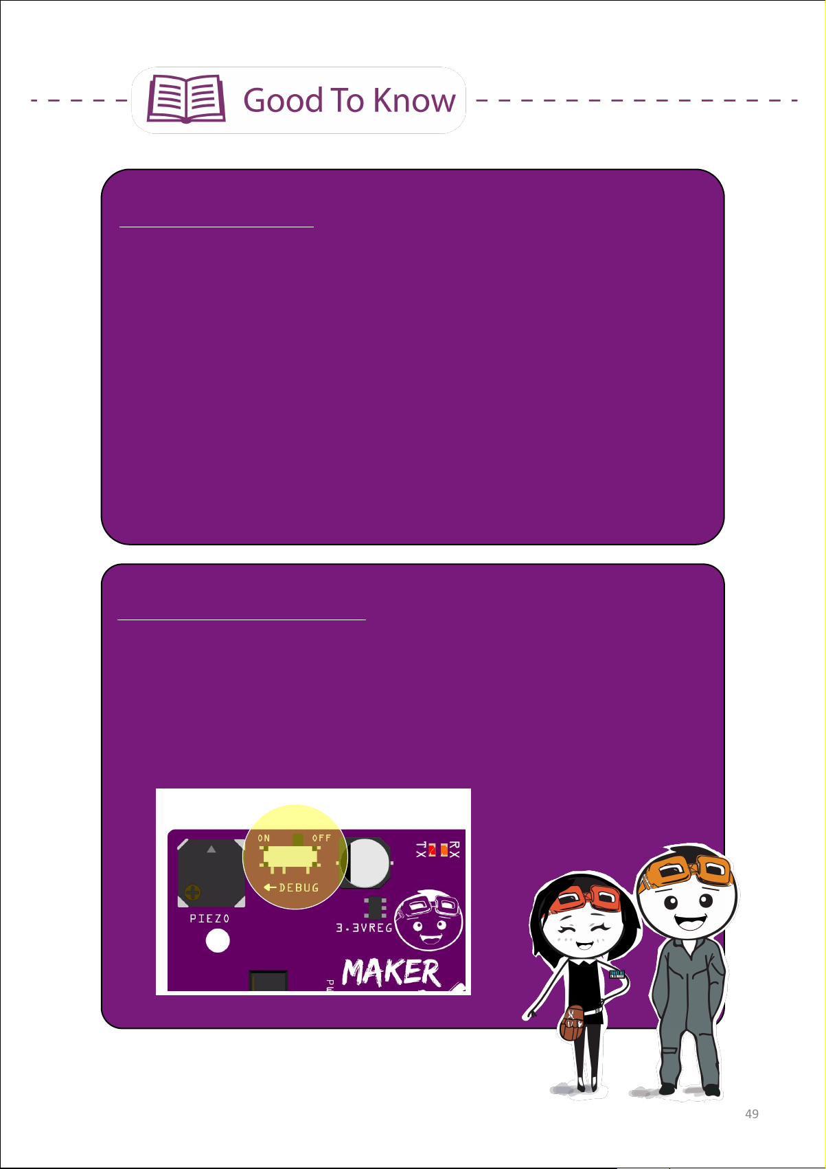
MAKER UNO X'S FEATURE
1. The on-board piezo buzzer is connected to Pin 8. You need to
switch on the DEBUG mode to activate the piezo buzzer.
2. If you want to connect Pin 8 to another I/O device, remember to
switch off the DEBUG mode to deactivate the piezo buzzer.
49Simplifying Digital Making
Page 50
READING MUSIC SHEET
Notes
Rests
Relative
Length
Whole
Note
Half
Note
Quarter
Note
Eighth
Note
Sixteenth
Note
Beat(s)
421
1/2
1/4
Duration(ms)
1000
500
250
125
63
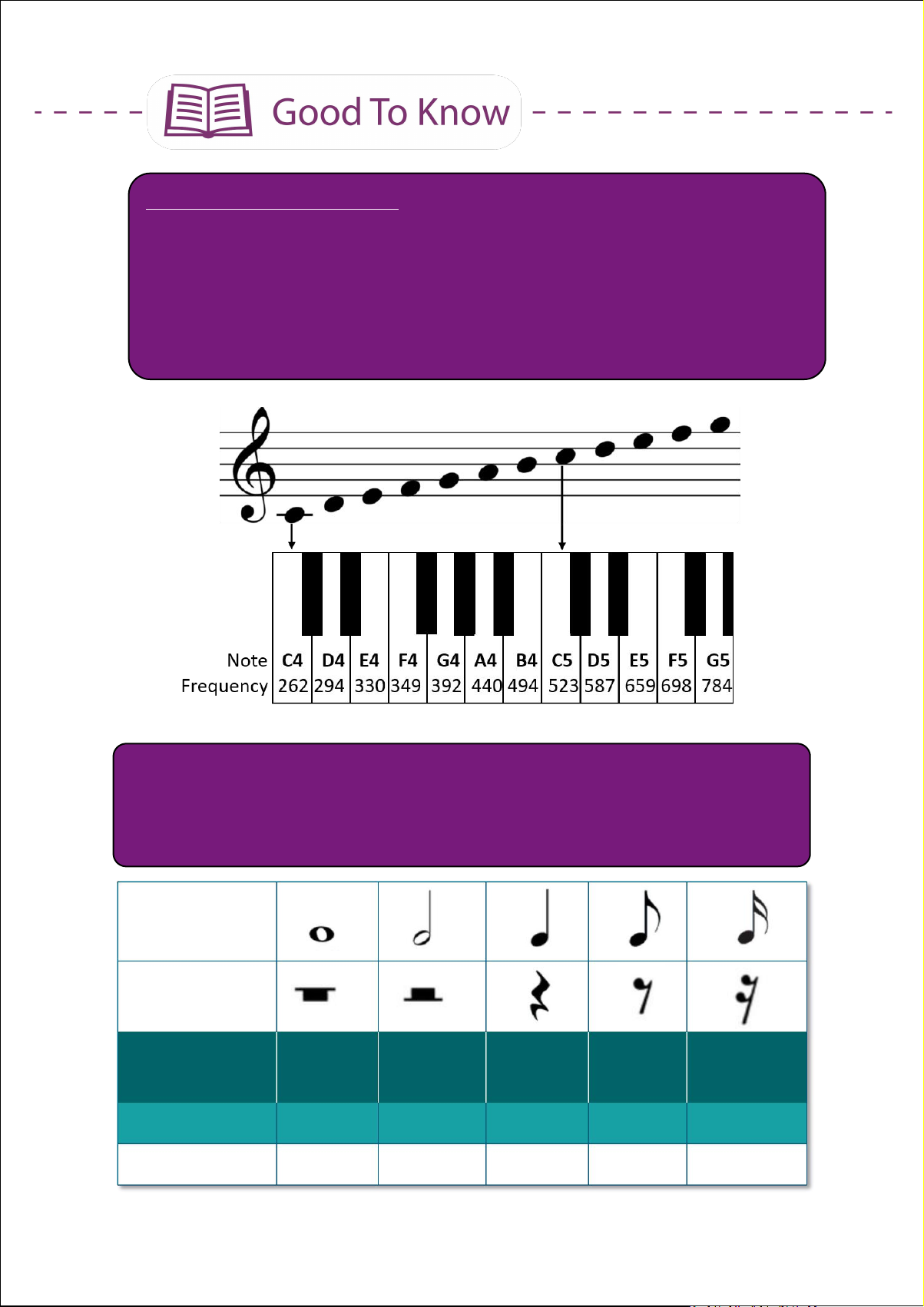
1. The position of a music note on the staff (i.e. the five horizontal
lines) determines its tone. The higher the note sits on the staff,
the higher the frequency of the sound and vice versa. You can
refer to the following link to get the frequencies for all 88 keys on
the piano : https://www.arduino.cc/en/Tutorial/ToneMelody
2. Different musical notations are used to tell us the duration (i.e.
how long) a note is to be played. In Arduino tone library, the
duration to play a quarter note (1 beat) is 250ms; assuming that
one whole note is played for 1 second.
50Simplifying Digital Making
Page 51

Let's compose the first line of “Happy Birthday” tune.
Note
Hap-
G4
-py
G4
Birth-
A4
-day
G4ToC5
You
B4
Frequency (Hz)
392
392
440
392
523
494
Duration (ms)
125
125
250
250
250
500
1. Modify your previous code into the following and then upload to your
board.
Project 9: Compose ”Happy Birthday” Melody
Project_9
void setup() {
pinMode(8, OUTPUT);
tone (8, 392, 125);
delay (163);
tone (8, 392, 125);
delay (163);
tone (8, 440, 250);
delay (325);
tone (8, 392, 250);
delay (325);
tone (8, 523, 250);
delay (325);
tone (8, 494, 500);
delay (650);
}
51Simplifying Digital Making
Page 52

2. Check your result.
Click here or scan
QR code to watch
the demo video.
The buzzer will play the first line of “Happy
Birthday” tune one time.
Project_9
void setup() {
pinMode(8, OUTPUT);
tone (8, 392, 125);
delay (163);
tone (8, 392, 125);
delay (163);
tone (8, 440, 250);
delay (325);
tone (8, 392, 250);
delay (325);
tone (8, 523, 250);
delay (325);
tone (8, 494, 500);
Set Pin 8 (connected to on-board
piezo buzzer) as output.
Play tone 'G4' 392Hz for 125ms.
Play tone 'G4' 392Hz for 125ms.
Play tone 'A4' 440Hz for 250ms.
Play tone 'G4' 392Hz for 250ms.
Play tone 'C5' 523Hz for 250ms.
delay (650);
}
Play tone 'B4' 494Hz for 500ms.
52Simplifying Digital Making
Page 53
CODING SYNTAX
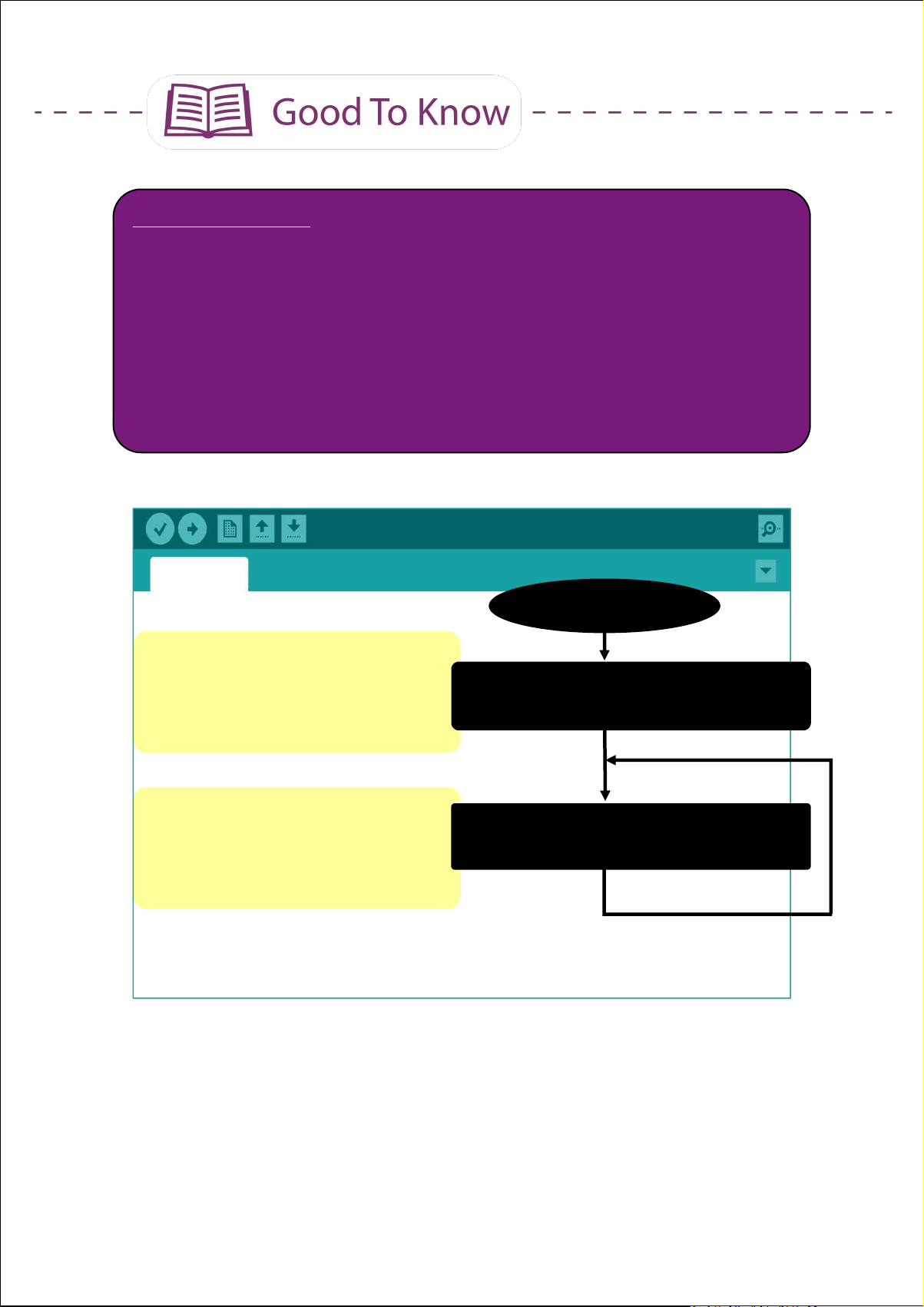
1. Did you notice that Project_9 melody only plays once and it
doesn't keep repeating like in the previous project?
This is because the entire code is written under void setup()
instead of void loop(). In other words, the code will be executed
line by line upon powering up Maker UNO X and will not be
repeated again unless the reset button is pressed.
Sketch
Start
void setup() {
// put your setup code here,
to run once:
}
void loop() {
// put your main code here,
to run repeatedly:
}
Do this once (upon powering up or
when reset button is pressed)
Do this repeatedly (until powered
off or reset button is pressed)
53Simplifying Digital Making
Page 54

Project 10: Optimize Your Code
Instead of manually keying in the note frequencies and durations line by
line, we can optimize our code using a given sample code. This allows us
to compose a long melody easily.
1. To open the toneMelody sample code, go to
File > Examples > 02 Digital > toneMelody
In the example given, every note's frequency is predefined from
note B0 to DS8. You can click on pitches.h tab to view the
predefined note frequencies.
54Simplifying Digital Making
Page 55
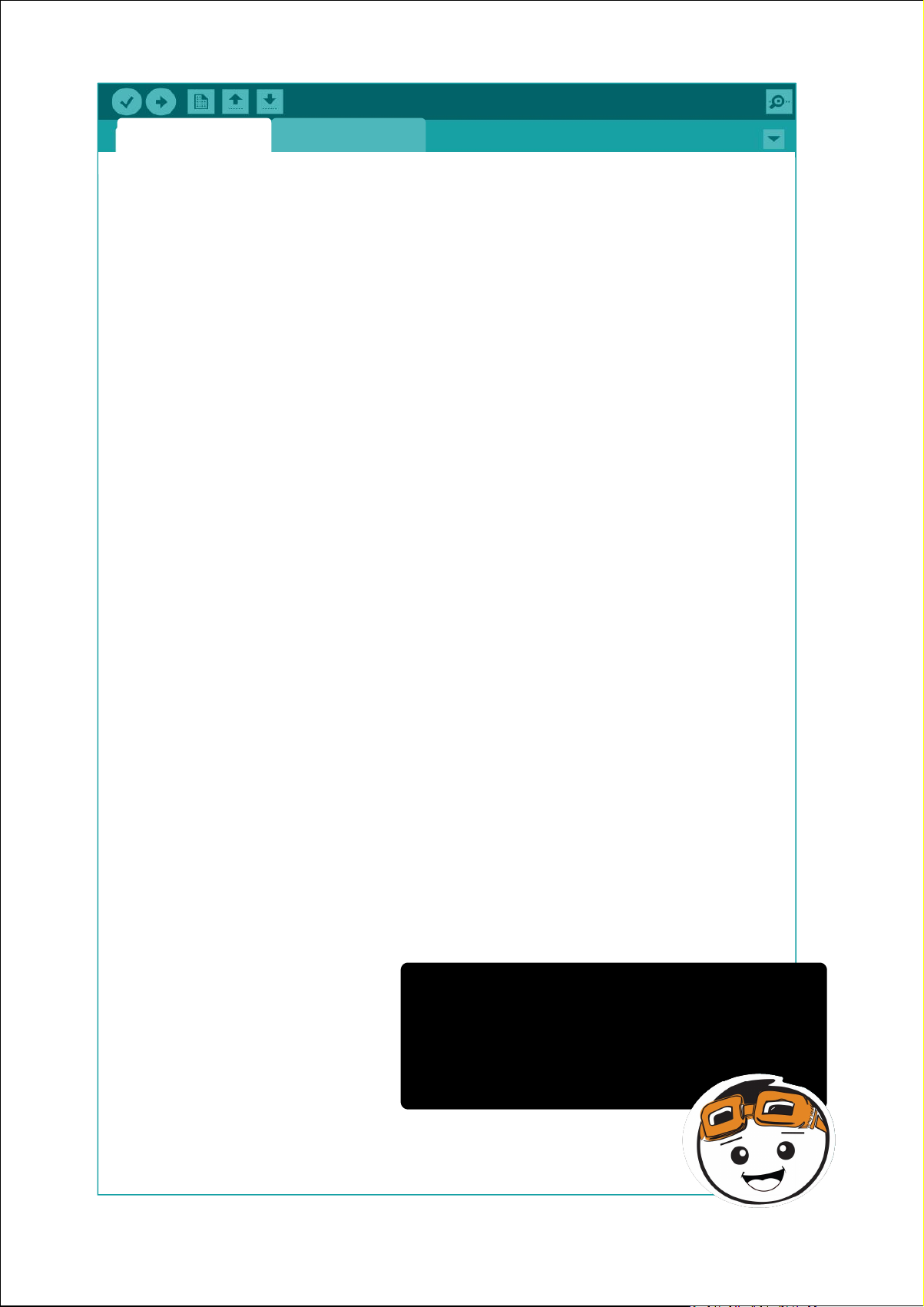
toneMelody pitches.h
#include "pitches.h"
// notes in the melody:
int melody[] = {
NOTE_C4, NOTE_G3, NOTE_G3, NOTE_A3, NOTE_G3, 0, NOTE_B3,
NOTE_C4
};
// note durations: 4 = quarter note, 8 = eighth note, etc.:
int noteDurations[] = {
4, 8, 8, 4, 4, 4, 4, 4
};
void setup() {
// iterate over the notes of the melody:
for (int thisNote = 0; thisNote < 8; thisNote++) {
// to calculate the note duration, take one second divided by the
note type.
//e.g. quarter note = 1000 / 4, eighth note = 1000/8, etc.
int noteDuration = 1000 / noteDurations[thisNote];
tone(8, melody[thisNote], noteDuration);
// to distinguish the notes, set a minimum time between them.
// the note's duration + 30% seems to work well:
int pauseBetweenNotes = noteDuration * 1.30;
delay(pauseBetweenNotes);
// stop the tone playing:
noTone(8);
}
}
This is the sample toneMelody sketch
created by Tom Igoe. Upload this code to
your Maker UNO X and you will hear the
catchy ending of the song “Shave and a
Haircut, Two Bits”.
void loop() {
// no need to repeat the melody.
}
55Simplifying Digital Making
Page 56
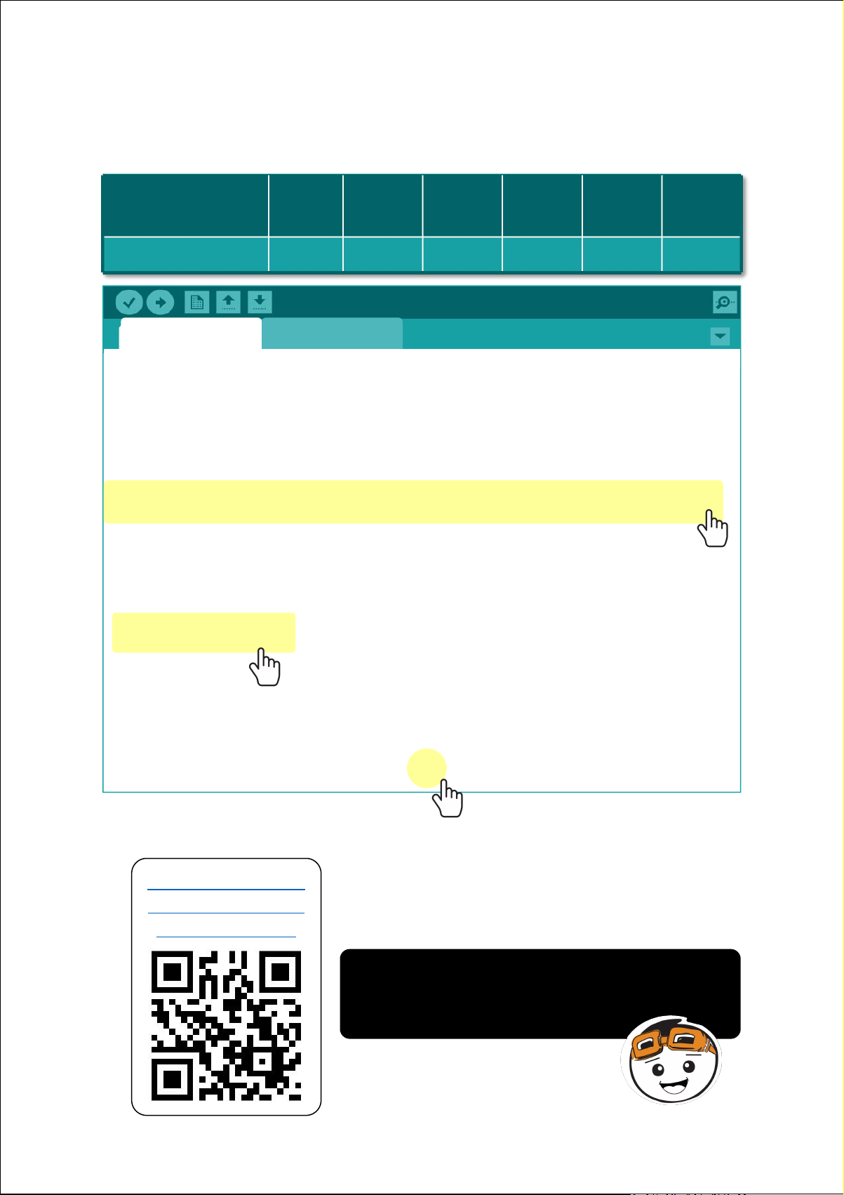
2. Modify the sample sketch to play the first line of “Happy Birthday”
NOTE_
Hap-
G4
-py
G4
Birth-
A4
-day
G4ToC5
You
B4
noteDurations
88444
2
#include "pitches.h"
// notes in the melody:
int melody[] = {
NOTE_G4, NOTE_G4, NOTE_A4, NOTE_G4, NOTE_C5, NOTE_B4
tune - replace the notes in the melody, their corresponding note
durations, and the total number of notes to play, as follows:
Project_10 pitches.h
};
// note durations: 4 = quarter note, 8 = eighth note, etc.:
int noteDurations[] = {
8, 8, 4, 4, 4, 4, 2
};
void setup() {
// iterate over the notes of the melody:
for (int thisNote = 0; thisNote < 6 ; thisNote++) {
3. Compile and upload your code. Check your result.
Click here or scan
QR code to watch
the demo video.
Similar to Project 9, the buzzer will play
the first line of “Happy Birthday” tune one
time.
Simplifying Digital Making
56
Page 57
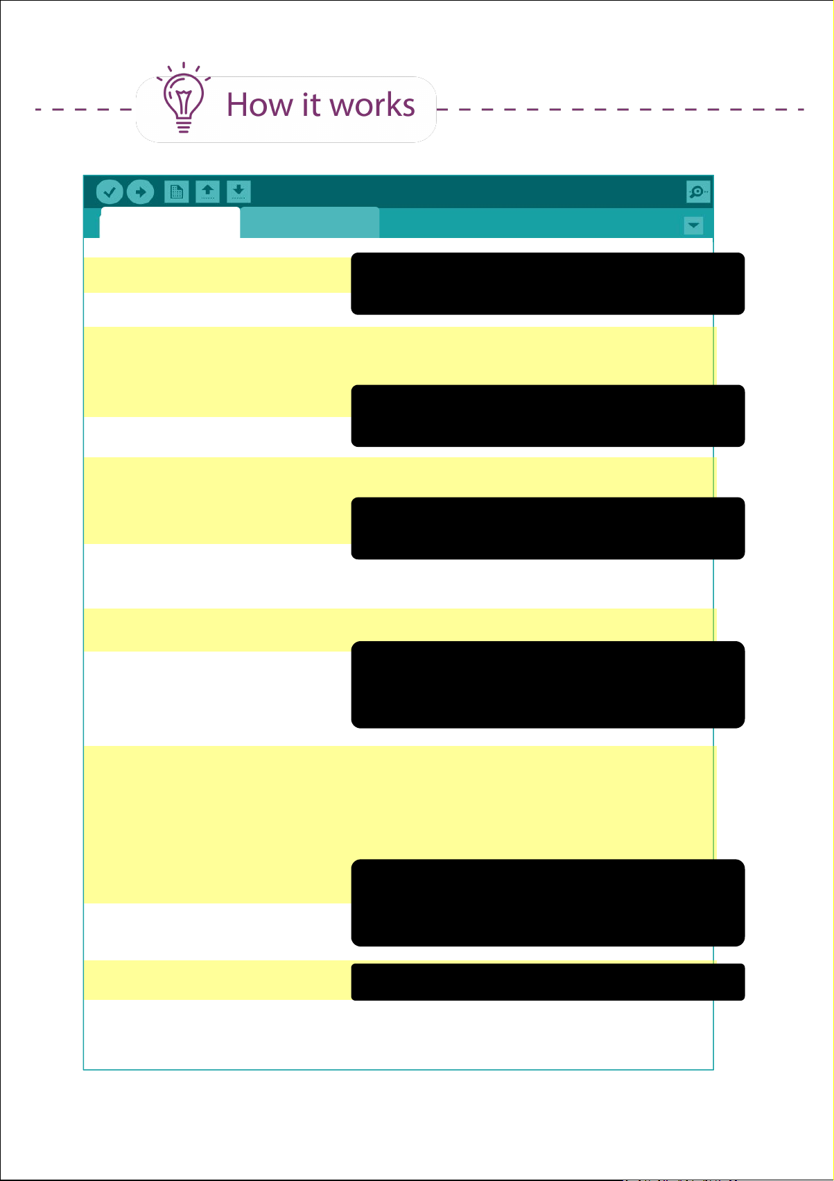
toneMelody pitches.h
#include "pitches.h"
Import all the pitch values for typical notes
as defined in pitches.h
int melody[] = {
NOTE_G4, NOTE_G4, NOTE_A4, NOTE_G4, NOTE_C5, NOTE_B4
};
Define melody[ ] array with the notes to be
played in sequence.
int noteDurations[] = {
8, 8, 4, 4, 4, 4, 2
};
Define noteDurations [ ] array with the
corresponding note durations.
void setup() {
for (int thisNote = 0; thisNote < 6; thisNote++) {
For loop to get the program to play each
note in sequence. 6 here refers to the
number of notes to be played.
int noteDuration = 1000 / noteDurations[thisNote];
tone(8, melody[thisNote], noteDuration);
int pauseBetweenNotes = noteDuration * 1.30;
delay(pauseBetweenNotes);
Similar to Project_9 code, this tells the
program to play each tone and then hold
for 30% longer of the note duration.
noTone(8);
Stop playing any tone.
}
}
57Simplifying Digital Making
Page 58

CODING SYNTAX
1. To use “for” statement:
for (initialization; condition; increment)
{
//statement(s)
}
Example:
void loop() {
digitalWrite(2,HIGH);
delay (1000);
digitalWrite(3,HIGH);
delay (1000);
digitalWrite(4,HIGH);
These lines of code from
Project_3 can be shortened into
just three lines using for
statement, as shown below:
delay (1000);
digitalWrite(5,HIGH);
delay (1000);
digitalWrite(6,HIGH);
delay (1000);
for (int i=2; i<8; i++)
{
digitalWrite (i , HIGH);
delay (1000);
}
digitalWrite(7,HIGH);
delay (1000);
}
2. When we have many variables of the same data type, we can
use an array and introduce all the variables using only one line
of code. To use an “array”:
type arrayName [ ] = { list of variables}
type: data type, e.g. int, char ,
arrayName = any name which identifies the array
Example:
int melody[ ] = { NOTE_C4, NOTE_D4, NOTE_E4 }
58Simplifying Digital Making
Page 59
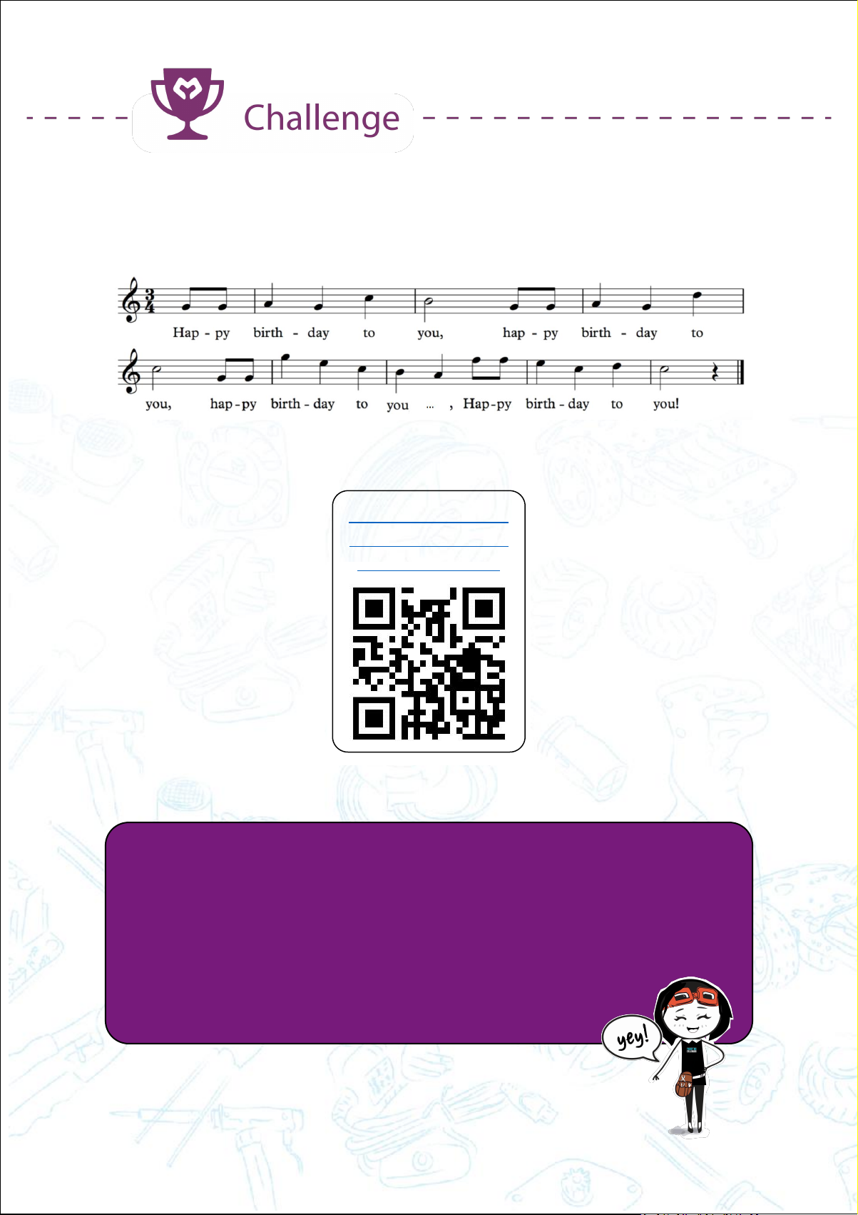
Task: Program your Maker UNO X to play a complete “Happy Birthday”
tune when the on-board switch is pressed.
Click here or scan
QR code to watch
the demo video.
CONGRATULATIONS! You have completed Lesson 4 and learnt the
following:
1. How to program Maker UNO X to play tones.
2. How to compose a simple melody using Maker UNO X.
3. How to load a sample program from Arduino library.
4. How to use for statement.
59Simplifying Digital Making
Page 60

LESSON 5
ANALOG INPUT
Page 61

Project 11: Display Analog Value on Serial Monitor
1. Get ready these components.
Jumper wire
2. Construct the circuit as shown below.
Potentiometer
61Simplifying Digital Making
Page 62
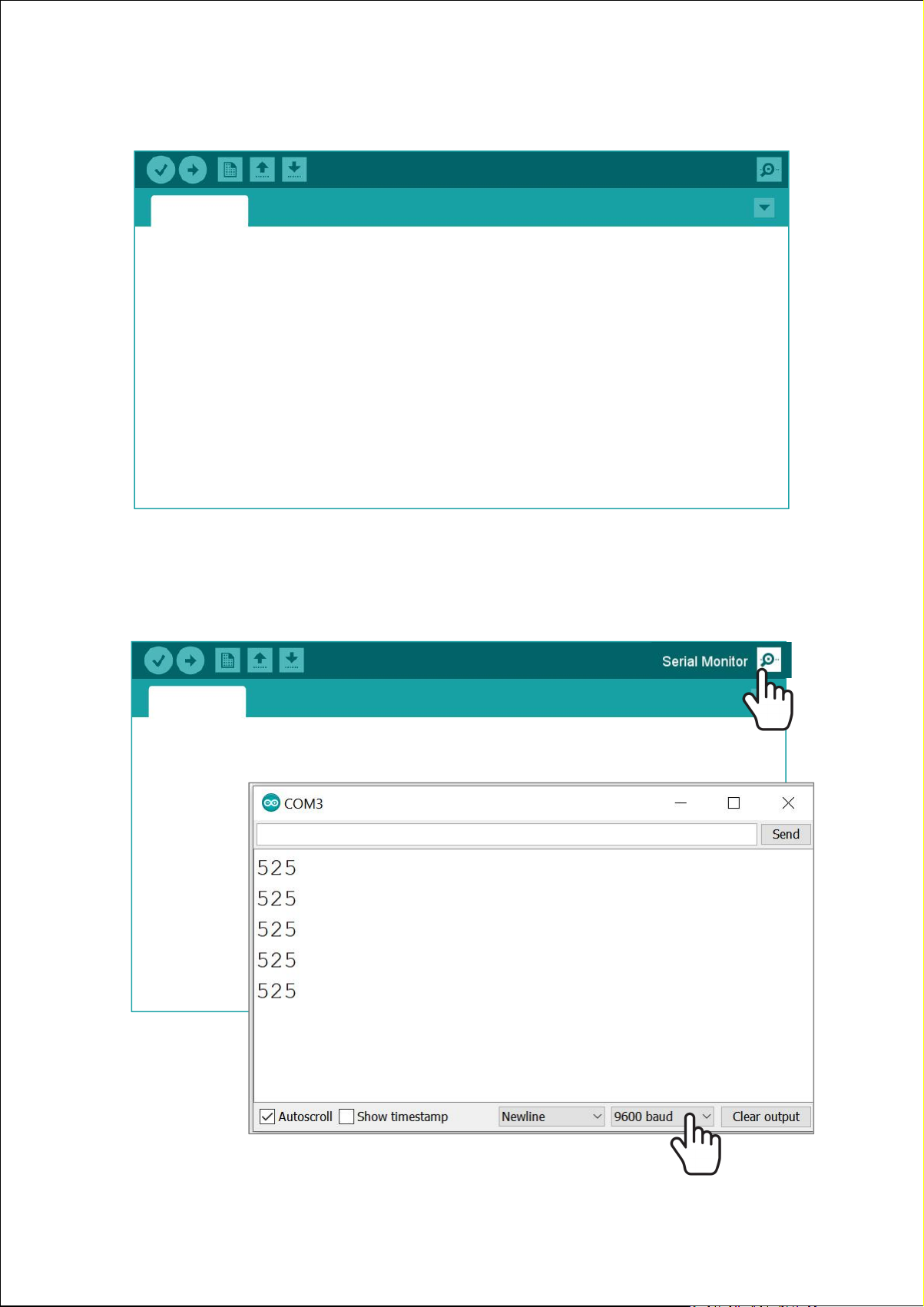
3. Write and upload the following code to your board.
Project_11
void setup() {
Serial.begin(9600);
}
void loop() {
Serial.println(analogRead(A0));
delay(1000);
}
4. Once uploaded, click on the serial monitor button on the toolbar. A
new window will pop up on your screen. Make sure that the baud rate
is set to 9600 baud.
Project_11
void setup() {
Serial.begin(9600);
}
void loop() {
Serial.println(analogRead(A0));
delay(1000);
}
62Simplifying Digital Making
Page 63
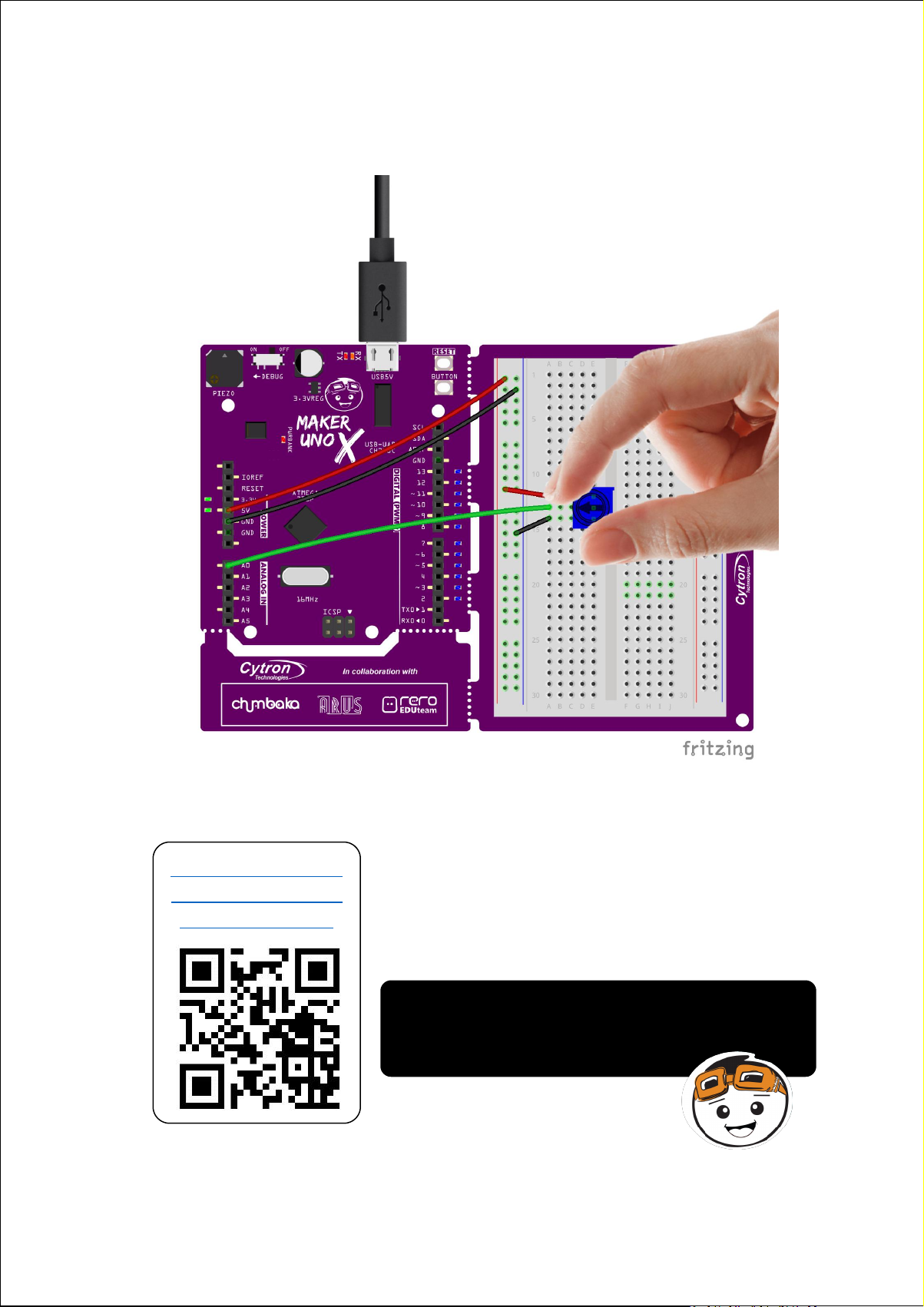
5. Observe the value displayed on the serial monitor window as you turn
the potentiometer clockwise, and then counter clockwise.
6. Check your result.
Click here or scan
QR code to watch
the demo video.
The values displayed on the serial monitor
are the analog readings provided by the
potentiometer.
63Simplifying Digital Making
Page 64
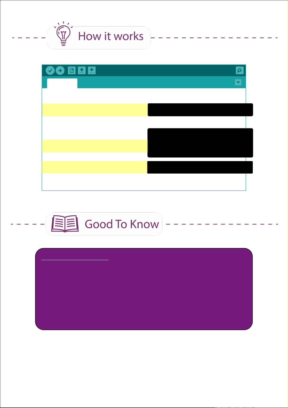
Project_11
void setup() {
Serial.begin(9600);
}
void loop() {
Serial.println(analogRead(A0));
delay(1000);
}
Setup serial communication
Read the analog value of pin A0
and display the value in the
serial monitor window.
Wait for 1 second.
ARDUINO FUNCTION
1. Only pins A0, A1, A2, A3, A4 and A5 have analog input function.
Hence, we need to connect analog sensors to these pins if we
want to get analog input values.
2. Digital input has only 2 possible values; either 0 (LOW) or 1
(HIGH).Analog input values range from 0 to 1023.
64Simplifying Digital Making
Page 65

Project 12: Read Analog IR Sensor
IR Sensor
VCC
GND
D0
A0
Maker UNO X
5V
GND
--
A0
1. Get ready these components.
Jumper wire
2. Construct the circuit as shown below.
IR Sensor
65Simplifying Digital Making
Page 66
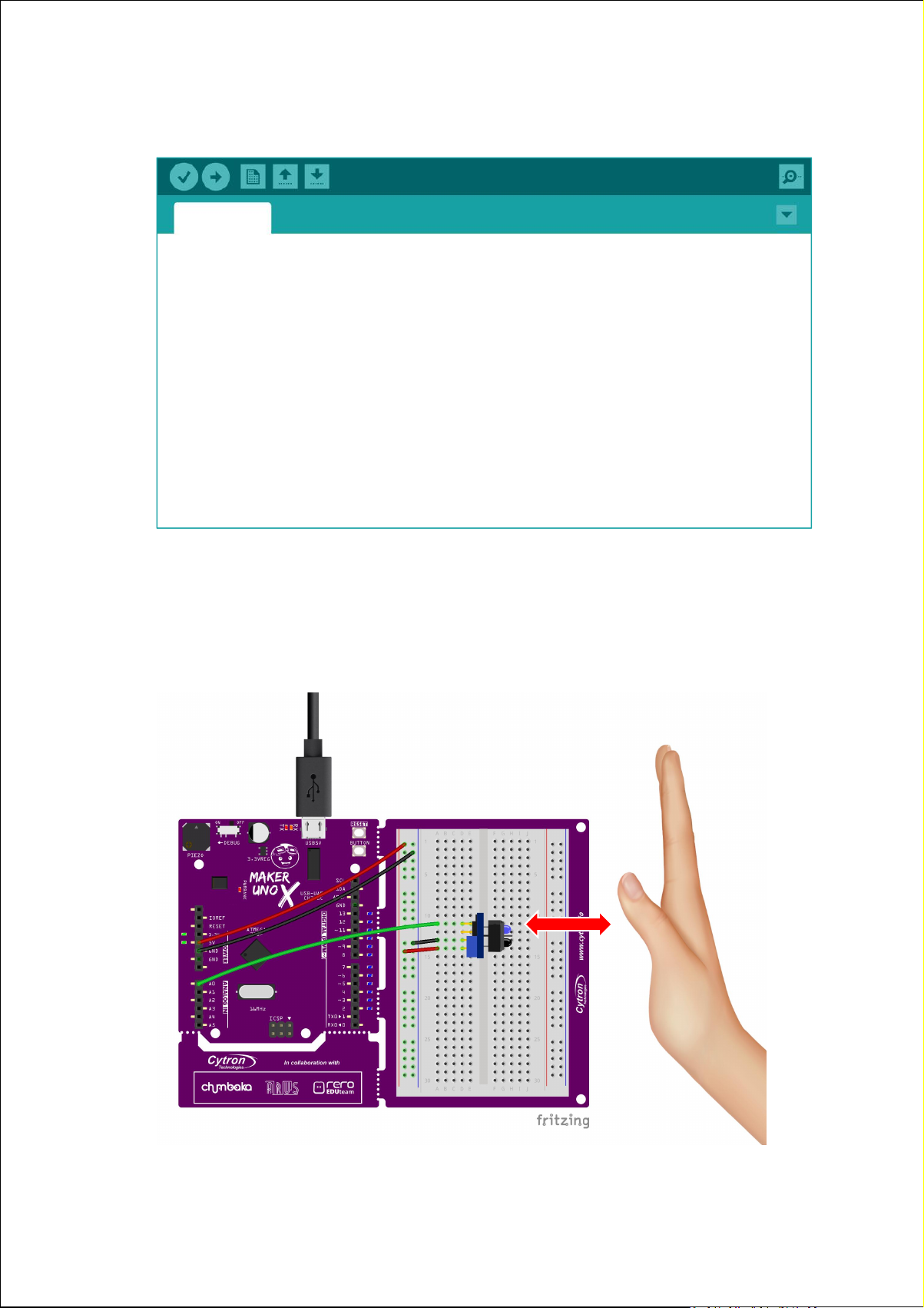
3. Upload the same program used in Project_11 to your board.
Project_12
void setup() {
Serial.begin(9600);
}
void loop() {
Serial.println(analogRead(A0));
delay(1000);
}
4. Once uploaded, click on the serial monitor button. Place your hand in
front of the sensor. Observe the value displayed on the serial monitor
window as you move your palm towards the IR sensor, and then
away from it.
66Simplifying Digital Making
Page 67

5. Check your result.
Click here or scan
QR code to watch
the demo video.
What do you observe? Does the IR
reading increase or decrease as you
move the box towards the sensor?
What is the reading when you remove
the box (no obstacle)?
Infrared (IR) Sensor
1. An infrared (IR) sensor consists
of two parts - IR transmitter (IR
LED) and IR receiver
(photodiode).
2. When powered up, the
transmitter will emit IR light. If
there is an object placed in front
of the sensor, the IR light will be
reflected back to the receiver.
3. The intensity of the IR light
detected by the receiver is then
converted into an analog value
which you can observe in the
serial monitor window.
IR Transmitter
IR Receiver
Distance: FAR - IR Reading: HIGH
IR Transmitter
4. The IR reading changes in
proportion to the distance
between the object and the IR
sensor.
IR Receiver
Distance: NEAR - IR Reading: LOW
67Simplifying Digital Making
Page 68
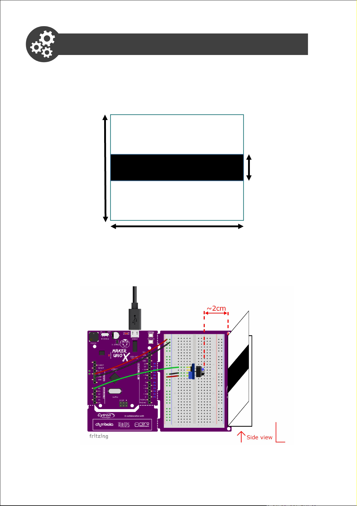
Project 13 : IR Sensor to Detect Black Line
1. Get ready a piece of white cardboard and a black marker pen. Use
the black marker pen to draw a thick black line (about 2cm in width)
across the centre of the cardboard as shown below.
8 cm
2cm
10 cm
2. Fold the cardboard and place it in front of the IR sensor as shown
below. Fix the distance between the cardboard and the sensor at
approximately 2cm.
68Simplifying Digital Making
Page 69

3. Slide the cardboard horizontally, from one end to the other. Observe
Condition
IR Reading
White Surface
Black Line
and record the IR readings from the serial monitor when the IR
sensor is facing the white surface, and then the black line.
4. Write the following code into a new sketch and then upload to your
board.
Project_13
int irValue;
void setup() {
Serial.begin(9600);
pinMode (3, OUTPUT);
}
void loop() {
Serial.println(analogRead(A0));
irValue = analogRead(A0);
if (irValue > 500) {
digitalWrite (3, HIGH);
delay(200);
}
else {
digitalWrite (3, LOW);
delay(200);
}
}
69Simplifying Digital Making
Page 70
5. Check your result.
Click here or scan
QR code to watch
the demo video.
Did LED 3 light up when the black line is
detected? And go off when the white
surface is detected?
“irValue > 500” is the threshold for my case. You may need to change
the threshold value according to your readings in Step 4. You can
pick any value between the two conditions but it is good practice to
set the threshold value at midpoint.
You can use this formula to determine a suitable threshold value.
Threshold Value =
IR Reading when IR Reading when
( + )
facing WHITE surface facing BLACK line
2
70Simplifying Digital Making
Page 71
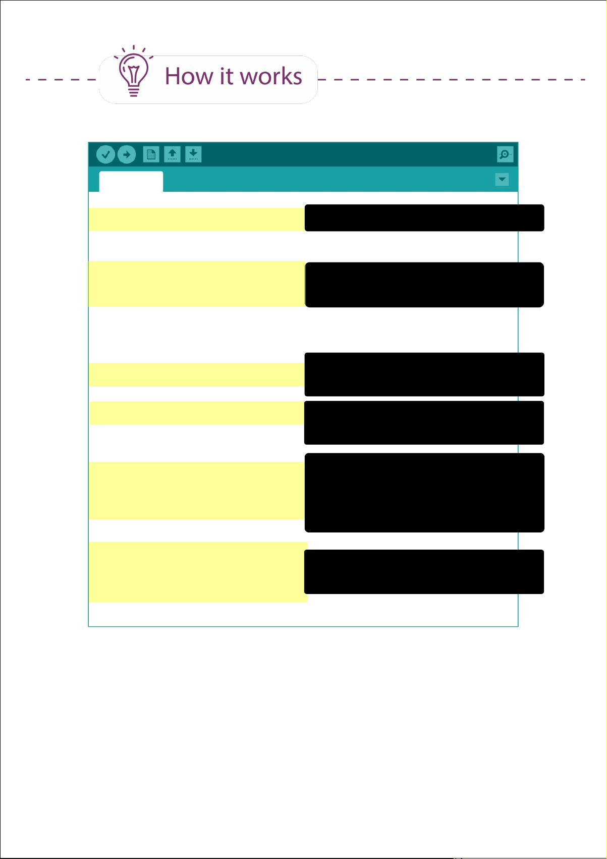
Project_13
int irValue;
void setup() {
Serial.begin(9600);
pinMode (3, OUTPUT);
}
void loop() {
Serial.println(analogRead(A0));
irValue = analogRead(A0);
if (irValue > 500) {
digitalWrite (3, HIGH);
delay(200);
}
Define a variable - “irValue”
Setup serial communication.
Set Pin 3 as output.
Read analog value of pin A0 and
display in serial monitor.
Assign analog input of pin A0 to
variable irValue.
Check irValue:
IF irValue > 500 (i.e. black line is
detected), turn on LED 3.
Hold for 200ms.
else {
digitalWrite (3, LOW);
delay(200);
}
}
Else, turn off LED 3.
Hold for 200ms.
71Simplifying Digital Making
Page 72
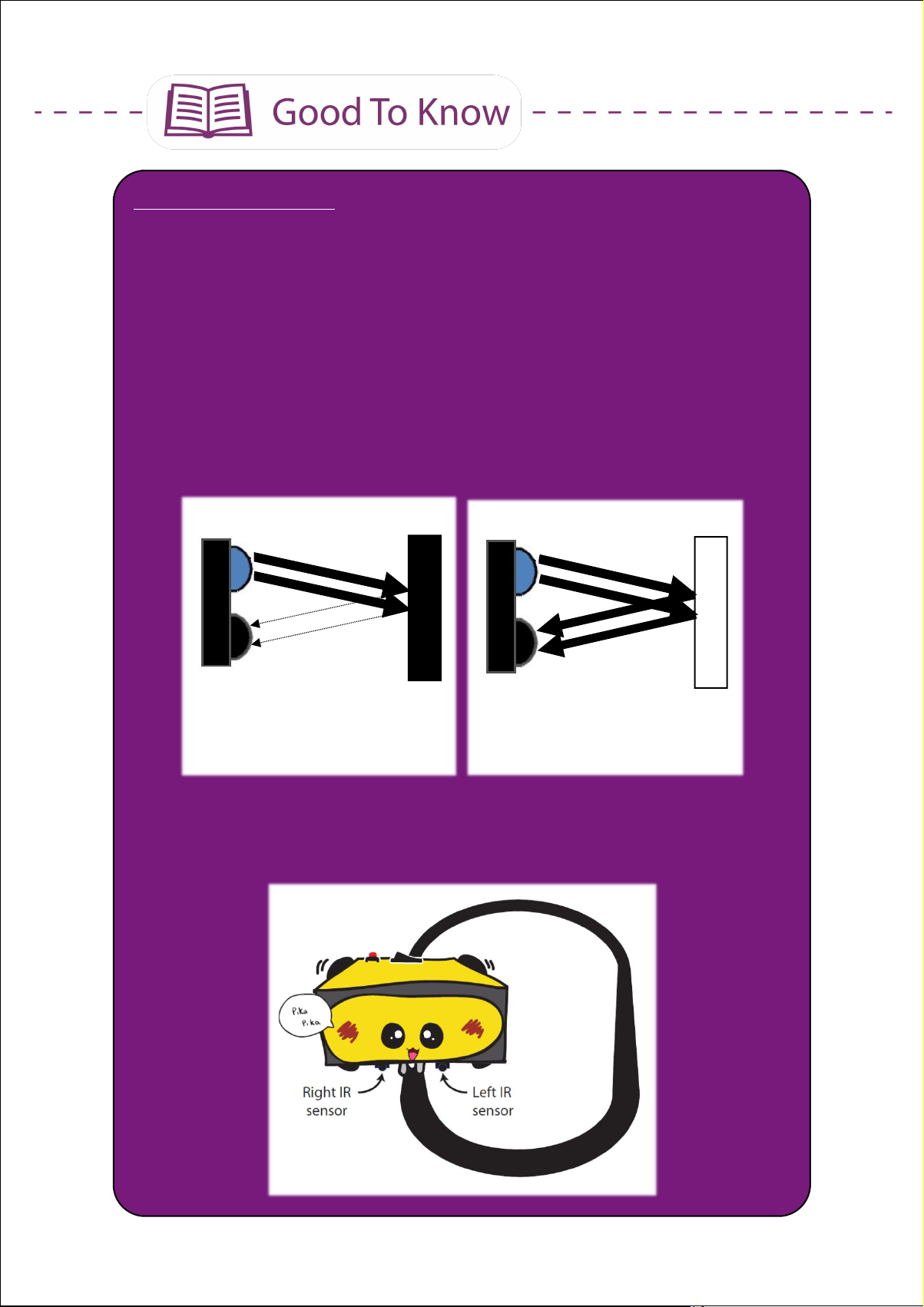
Infrared (IR) Sensor
IR sensors are commonly used to detect obstacles and measure
distances. Besides that, we can also use IR sensors to differentiate
black and white surfaces.
This is because a white (or light coloured) surface is able to reflect
most of the light from the IR transmitter, while a black (or dark
coloured) surface tends to absorb the light. Hence the IR receiver
will detect comparatively more light reflected from a white surface
than a black surface.
IR Transmitter
IR Receiver
BLACK Surface;
IR Reading - HIGH
IR Transmitter
IR Receiver
WHITE Surface;
IR Reading - LOW
Applying this concept, we can use multiple IR sensors arranged in a
straight line to build a line follower robot.
72Simplifying Digital Making
Page 73

CODING SYNTAX
In this project, the analog input value from the IR sensor keeps
changing depending on the colour of the object it is currently facing.
We need to store the value to a certain place and only summon it
when needed. To do that, we can assign a variable.
int variableName = value; OR int variableName;
variableName can be any word EXCEPT those already used as
keywords in Arduino IDE. You are encouraged to use descriptive
names, such as “irValue” or “distance”, so that you (or anyone
reading your code) can easily understand what the variable
represents.
73Simplifying Digital Making
Page 74
Task: Utilise the analog values from a potentiometer to change the
blinking speed for LED 3.
Click here or scan
QR code to watch
the demo video.
CONGRATULATIONS! You have completed Lesson 5 and learnt the
following:
1. How to read analog input.
2. How to use serial monitor.
3. IR sensor and how it works.
4. How to assign variable numbers.
74Simplifying Digital Making
Page 75

LESSON 6
DC MOTOR
Page 76
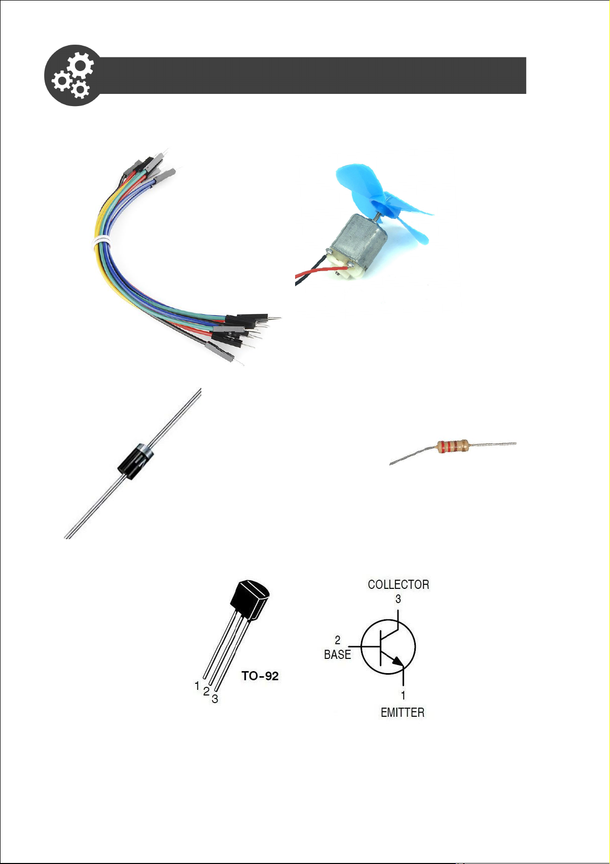
Project 14: Control a DC Motor
1. Get ready these components.
Jumper wire
Diode
The terminal with a white
stripe should connect to
the positive wire (red)
DC motor with blade
220 ohm resistor
2N2222 Transistor
76Simplifying Digital Making
Page 77
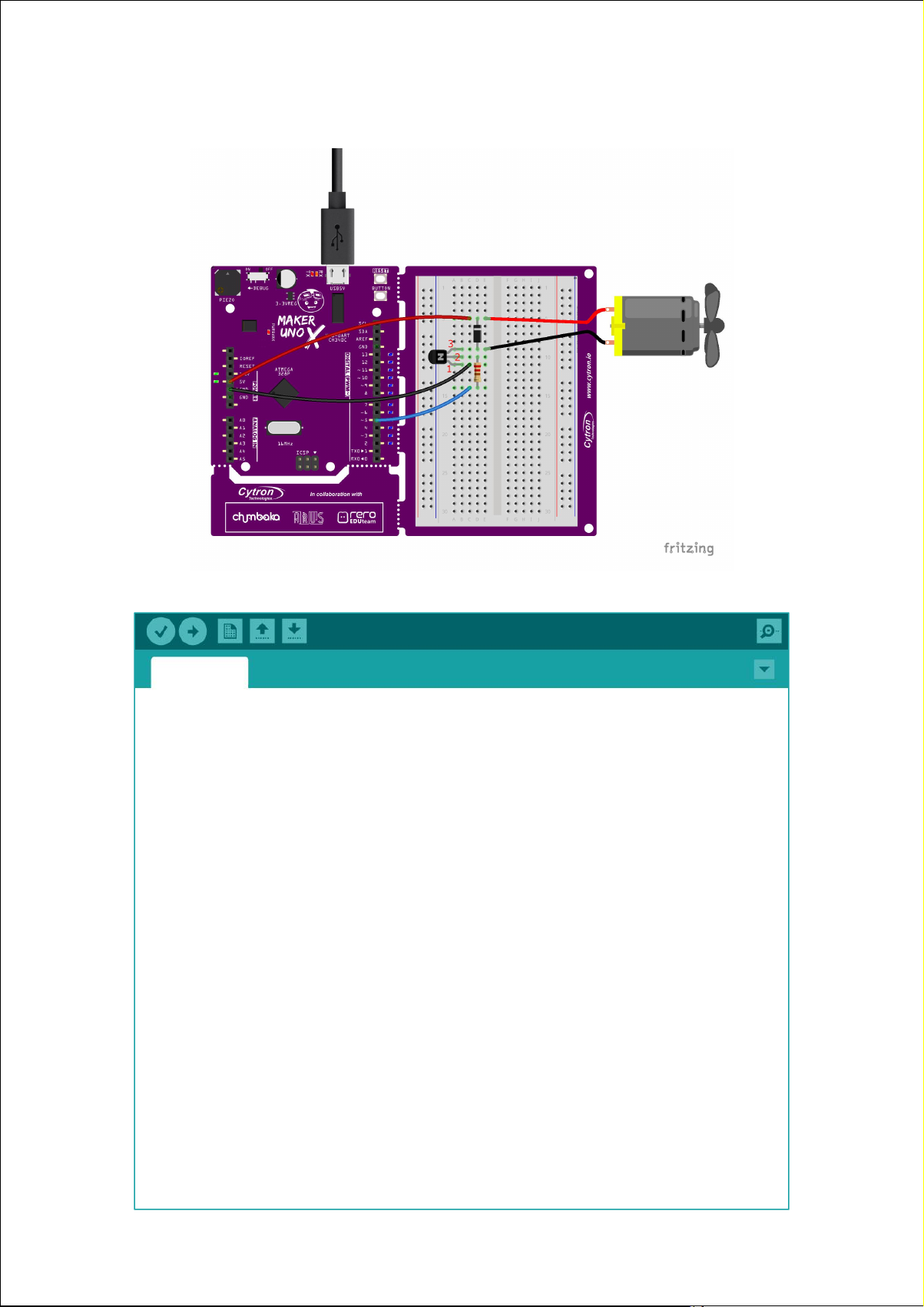
2. Construct the circuit as shown below:
3. Write and upload the following code to your board.
Project_14
void setup() {
pinMode(2, INPUT_PULLUP);
pinMode(5, OUTPUT);
}
void loop() {
if (digitalRead(2)==LOW) {
while(1) {
analogWrite(5, 255);
delay(3000);
analogWrite(5, 80);
delay(3000);
}
}
else digitalWrite(3, LOW);
}
77Simplifying Digital Making
Page 78
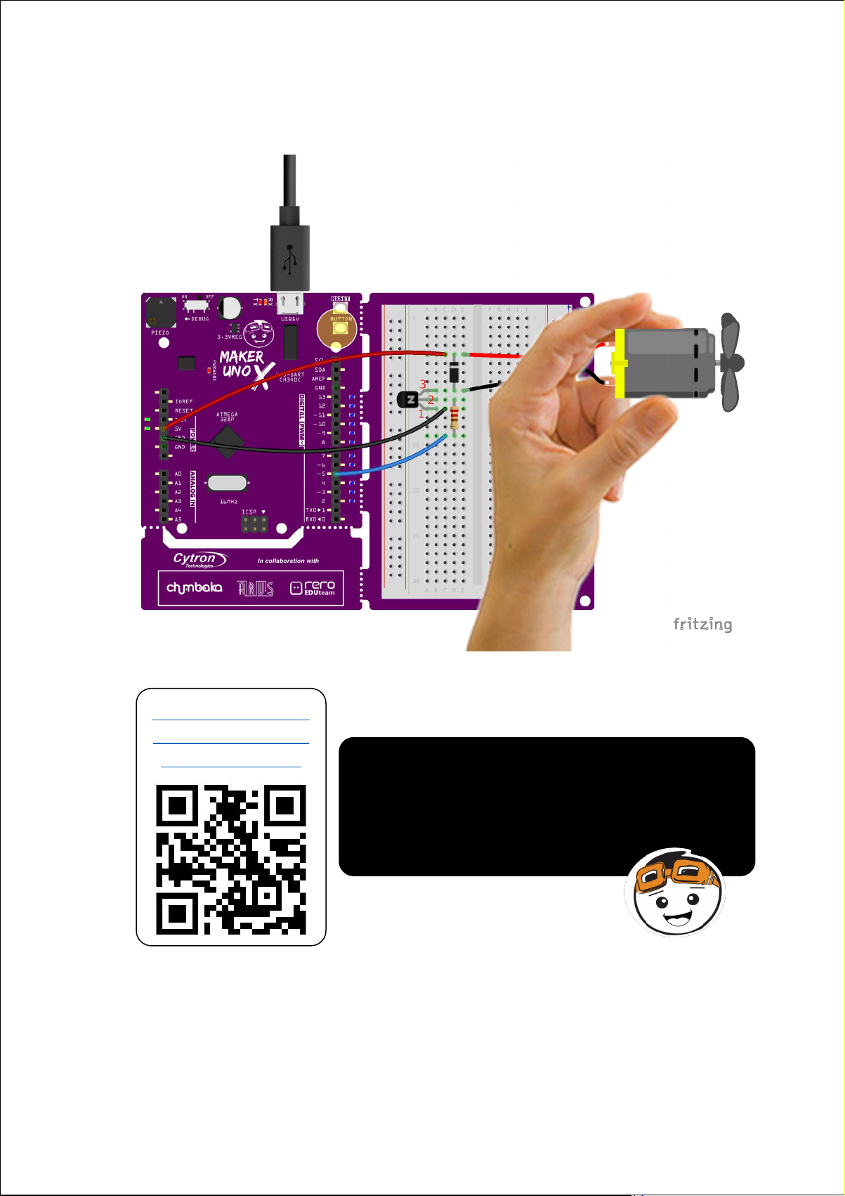
4. Once uploaded, press the on-board switch and observe the result.
Click here or scan
QR code to watch
the demo video.
When you press the switch, do you see the
motor starting to spin? It will continue to
spin continually, at full speed and then
medium speed alternately, until you power
off or press the reset button.
78Simplifying Digital Making
Page 79
Project_14
void setup() {
pinMode(2, INPUT_PULLUP);
pinMode(5, OUTPUT);
}
void loop() {
if (digitalRead(2)==LOW) {
while(1) {
analogWrite(5, 255);
delay(3000);
analogWrite(5, 80);
delay(3000);
}
}
else digitalWrite(5, LOW);
}
Set Pin 2 as input_pullup (switch).
Set Pin 5 as output.
Check Pin 2 value. IF Pin 2 value =
LOW (i.e. switch is pressed), always
set Pin 5 to 255 (motor spins at max
speed) for 3 seconds,
then set Pin 5 to 80 (motor spins at
medium speed) for 3 seconds.
Else set Pin 5 to LOW (motor is
turned off; not spinning).
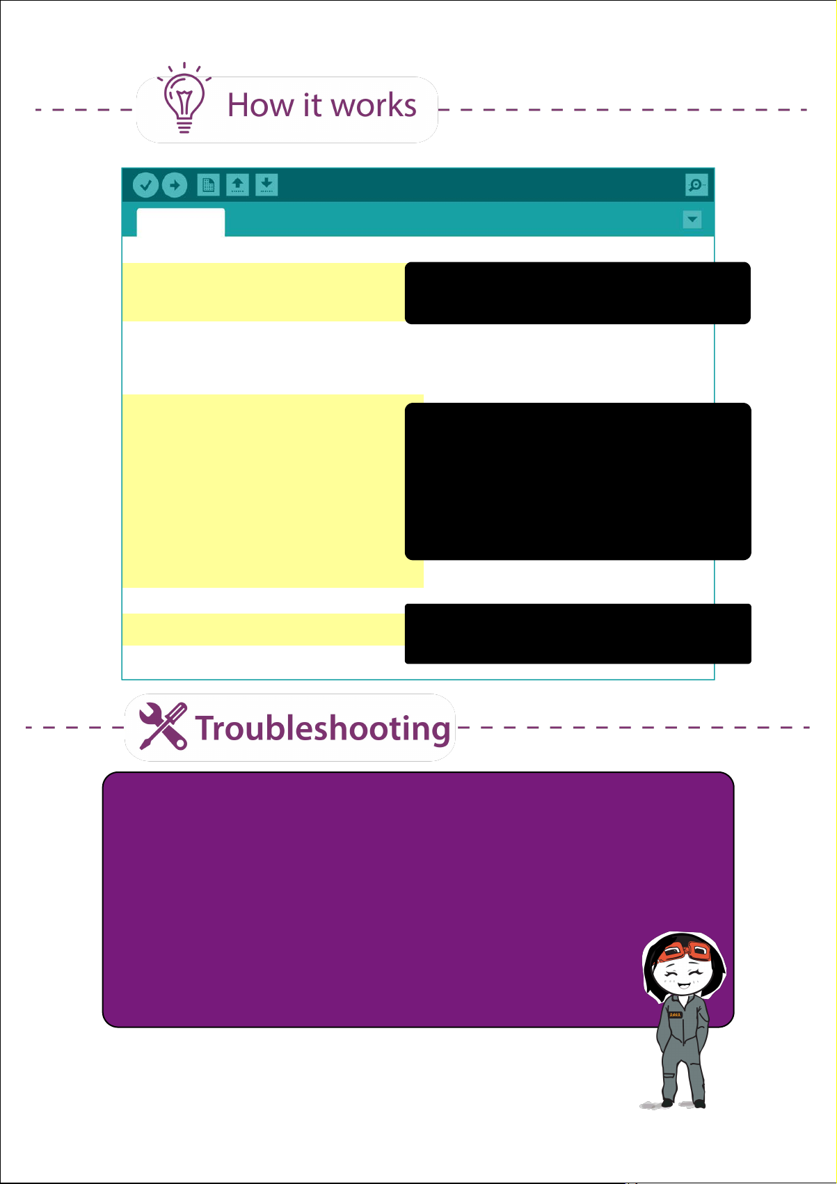
1. Make sure the DC motor is supported. The motor may not have
sufficient torque to spin if the blades are resting on a surface.
2. Turn on the Debug mode and observe the built-in LED at Pin 5.
After the switch is pressed, the LED should alternately light up at
full brightness for 3 seconds and then dim for another 3 seconds.
3. If #2 above is working but the motor is still not spinning,
you need to check your circuit and make sure that all
components are connected correctly.
79Simplifying Digital Making
Page 80

How to Control a DC Motor Speed?
To get a DC motor to spin, you need to apply suitable input voltage to
it. The typical input voltages for DC motors are 3V, 6V adn 12V. The
motor manufacturer will usually indicate the recommended input
voltage in the product specifications.
Nevertheless, motors can still work even when you apply lesser or
greater voltage than recommended. For the DC motor that we are
using in this project, the recommended voltage is 3-6V. Let's try to
apply 3.3V and 5V and see what happens.
Black wire is connected to GND
and red wire to 3.3V pin.
Black wire is connected to GND
and red wire to 5V pin.
We can observe that the speed of the DC motor changes with the
input voltage. The higher the input voltage, the faster the motor spins.
Thus in Project 14, when we set pin 5 value to 255, the motor spins
at full speed and then it slows down when pin 5 value is set to 80.
WARNING! Applying high voltage to a motor (beyond the
recommended voltage) will shorten a motor's life cycle in
the long run.
80Simplifying Digital Making
Page 81
How to Control a DC Motor's Spinning Direction?
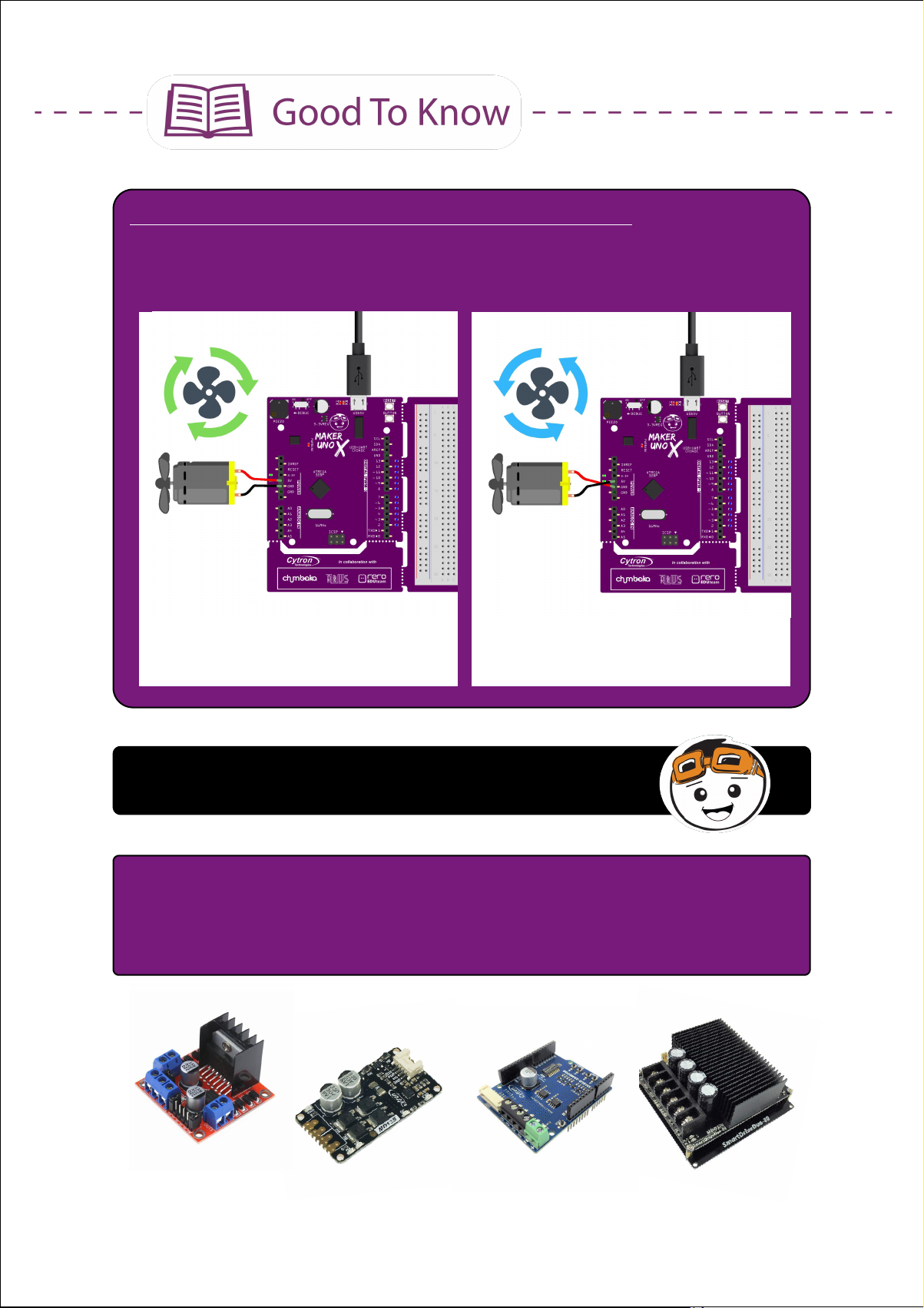
To change the spinning direction is easy - simply reverse the polarity
of the motor by switching the red wire and black wire connections.
Black wire is connected to GND
and red wire to 5V pin.
Black wire is connected to 5V pin
and red wire to GND.
Do you observe that the motor spins in the opposite
direction when we switch the wire connection?
Nevertheless, it is impractical to manually switch the wire connections
each time you want to change the spinning direction. In order to easily
control both the spinning direction and speed of a DC motor (without
modifying the circuit), we can use a motor driver, such as the following.
81Simplifying Digital Making
Page 82
Project 15: Controlling Motor Speed Using A Pushbutton
1. Write the following code and upload to your board.
Project_15
int mode = 0;
void setup() {
pinMode(2, INPUT_PULLUP);
pinMode(5, OUTPUT);
}
void loop() {
switch(mode) {
case 0:
analogWrite (5, 0);
break;
case 1:
analogWrite (5, 100);
break;
case 2:
analogWrite (5, 255);
break;
default:
mode = 0;
break;
}
if (digitalRead(2)==LOW) {
while(digitalRead(2)==LOW);
mode++;
if (mode==3)
mode=0;
}
}
82Simplifying Digital Making
Page 83
3. Once uploaded, press the on-board switch and observe the result.
Repeat several times and observe changes to the motor speed each
time the switch is pressed.
Click here or scan
QR code to watch
the demo video.
When you press the switch, the motor starts
spinning. And if you press again, the motor
spins faster (at full speed). The third time
you press the switch, the motor stops
spinning.
83Simplifying Digital Making
Page 84
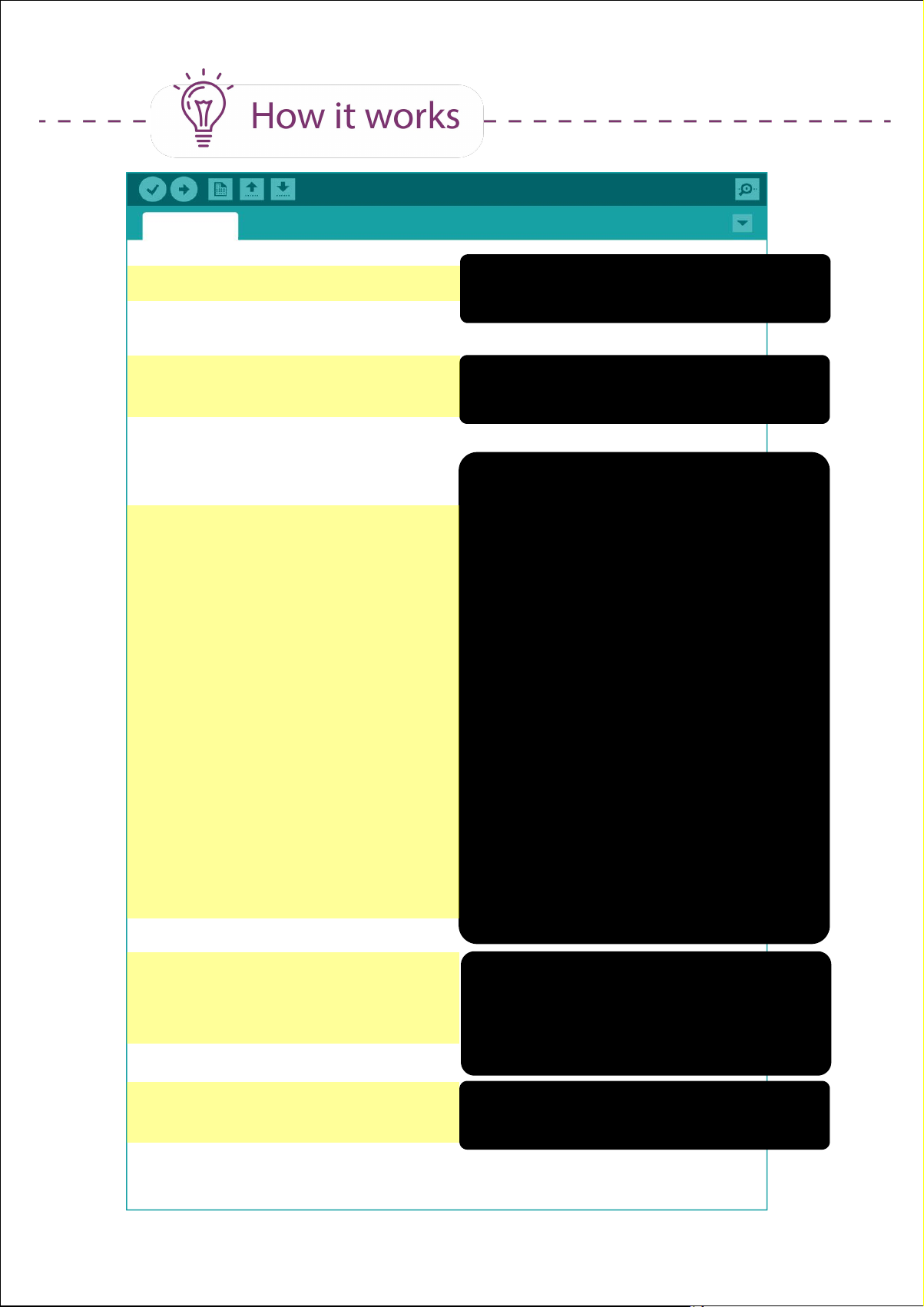
Project_15
int mode = 0;
void setup() {
pinMode(2, INPUT_PULLUP);
pinMode(5, OUTPUT);
}
void loop() {
switch(mode) {
case 0;
analogWrite (5, 0);
break;
case 1:
analogWrite (5, 100);
break;
Define a variable named “mode”
and set the initial value as 0.
Set Pin 2 as input_pullup (switch).
Set Pin 5 as output.
Set conditions for various cases
and statements to be executed
when each condition is met.
If mode = 0, motor at pin 5 runs at
speed 0 (i.e. not spinning)
If mode = 1, motor at pin 5 runs at
speed 100 (i.e. spinning slowly)
case 2:
analogWrite (5, 255);
break;
default:
mode = 0;
break;
}
if (digitalRead(2)==LOW) {
while(digitalRead(2)==LOW);
mode++;
if (mode==3)
mode=0;
}
}
If mode = 2, motor at pin 5 runs at
speed 255 (spinning at full speed)
If mode is neither 0,1 or 2, set
mode to 0.
If Pin 2 switch is pressed,
check Pin 2 switch again and wait
until it is released.
Update mode value by +1.
If mode = 3, update mode value to
0.
84Simplifying Digital Making
Page 85

CODING SYNTAX
1. Like if statements, switch...case controls the flow of a program
by allowing programmers to specify which lines of code to be
executed when the set conditions are met. This is useful when
you need to use the same switch to execute different sets of
program.
switch (var) {
case 1:
//do something when var equals 1
break;
case 2:
//do something when var equals 2
break;
default:
// if nothing else matches, do the default
// default is optional
break;
}
2. To stop the motor from spinning, you can write either of these:
digitalWrite (pin, LOW);
or
analogWrite (pin, 0);
85Simplifying Digital Making
Page 86
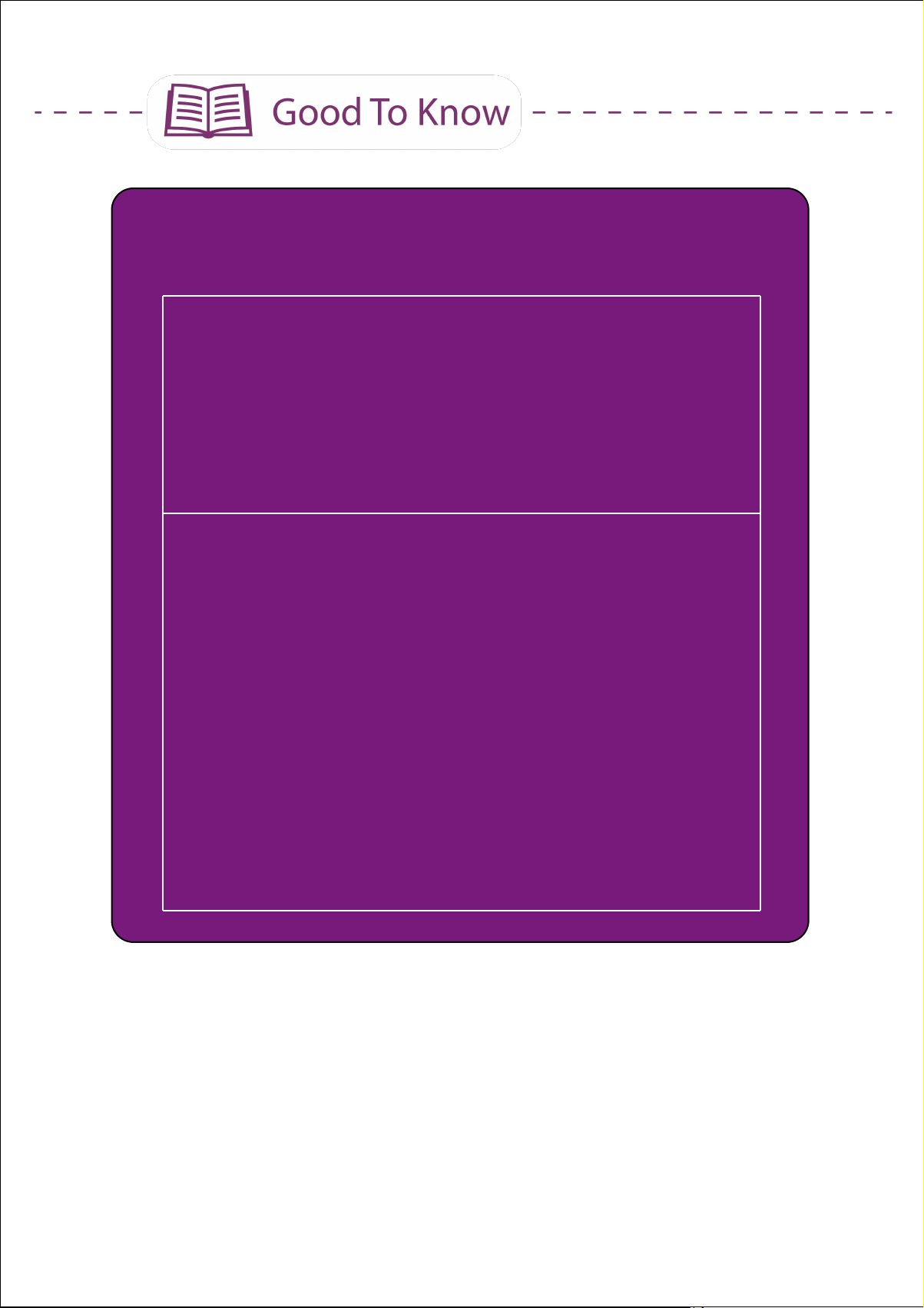
3. Did you notice that we didn't put a semicolon ; after while(1) in
Without “ ; “
while (condition) {
//if the condition is true, program will run all lines of code
inside { }
}
With “ ; “
while (condition) ;
//if the condition is true, it will only run this line until the
condition becomes false.
Example:
while(digitalRead(2)==LOW);
// If switch 2 is pressed (condition is true), the program will
stay at this line of code until switch 2 is released (condition
becomes false). Then, and only then will it move on to execute
the next line of code.
our previous projects but we added a semicolon after
while(digitalRead(2)==LOW) in this project?
86Simplifying Digital Making
Page 87
Task: Program the motor to run at a constant speed when you press and
hold the pushbutton. The motor stops when you release the button. And
when you press the pushbutton for the second time, the motor's speed
will change.
Click here or scan
QR code to watch
the demo video.
CONGRATULATIONS! You have completed Lesson 6 and learnt the
following:
1. How to construct a circuit to run a DC motor.
2. How to control a DC motor speed.
3. How to use switch..case statement.
87Simplifying Digital Making
Page 88

LESSON 7
ULTRASONIC
SENSOR
Page 89
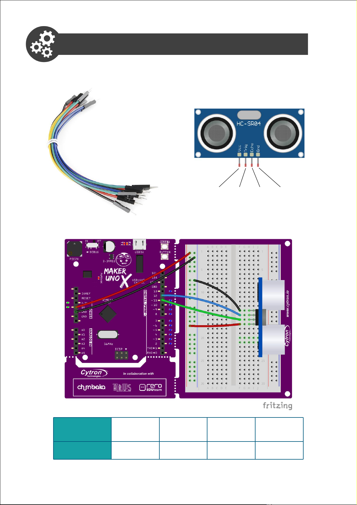
Project 16: Setting Up Ultrasonic Sensor
Ultrasonic
Sensor
VCC
TRIG
ECHO
GND
Maker UNO X
5V
PIN 11
PIN 12
GND
1. Get ready these components.
Jumper wire
Ultrasonic Sensor
VCC Trig Echo GND
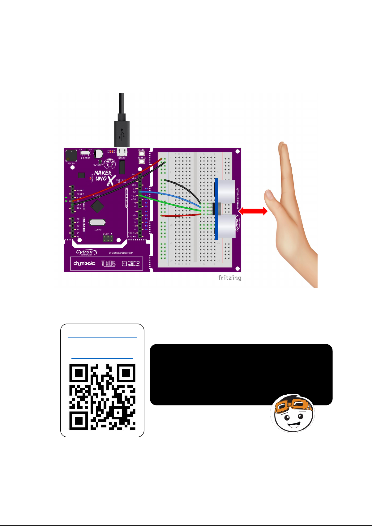
2. Construct the circuit as shown below.
89Simplifying Digital Making
Page 90
Connect the sensor at the edge of the breadboard
and ensure that the jumper wires are not blocking
the sensor.
3. Write and upload the following code to your board.
Project_16
long duration;
int distance;
void setup() {
pinMode(11, OUTPUT);
pinMode(12, INPUT);
Serial.begin (9600);
}
void loop() {
digitalWrite(11, LOW);
delayMicroseconds(2);
digitalWrite(11, HIGH);
delayMicroseconds(10);
digitalWrite(11, LOW);
duration = pulseIn (12, HIGH);
distance = duration*0.034/2;
delay(50);
Serial.print (“Distance = “);
Serial.print (distance);
Serial.println (“cm “);
}
90Simplifying Digital Making
Page 91
4. Once uploaded, click on the serial monitor button to view the result.
Place your hand in front ot the sensor. Observe the value displayed
on the serial monitor window as you move your palm towards the
ultrasonic sensor, and then away from it.
5. Check your result.
Click here or scan
QR code to watch
the demo video.
What do you observe? Does the ultrasonic
reading increase or decrease as you move
the box towards the sensor? What is the
reading when you remove the box (i.e. no
obstacle)?
91Simplifying Digital Making
Page 92
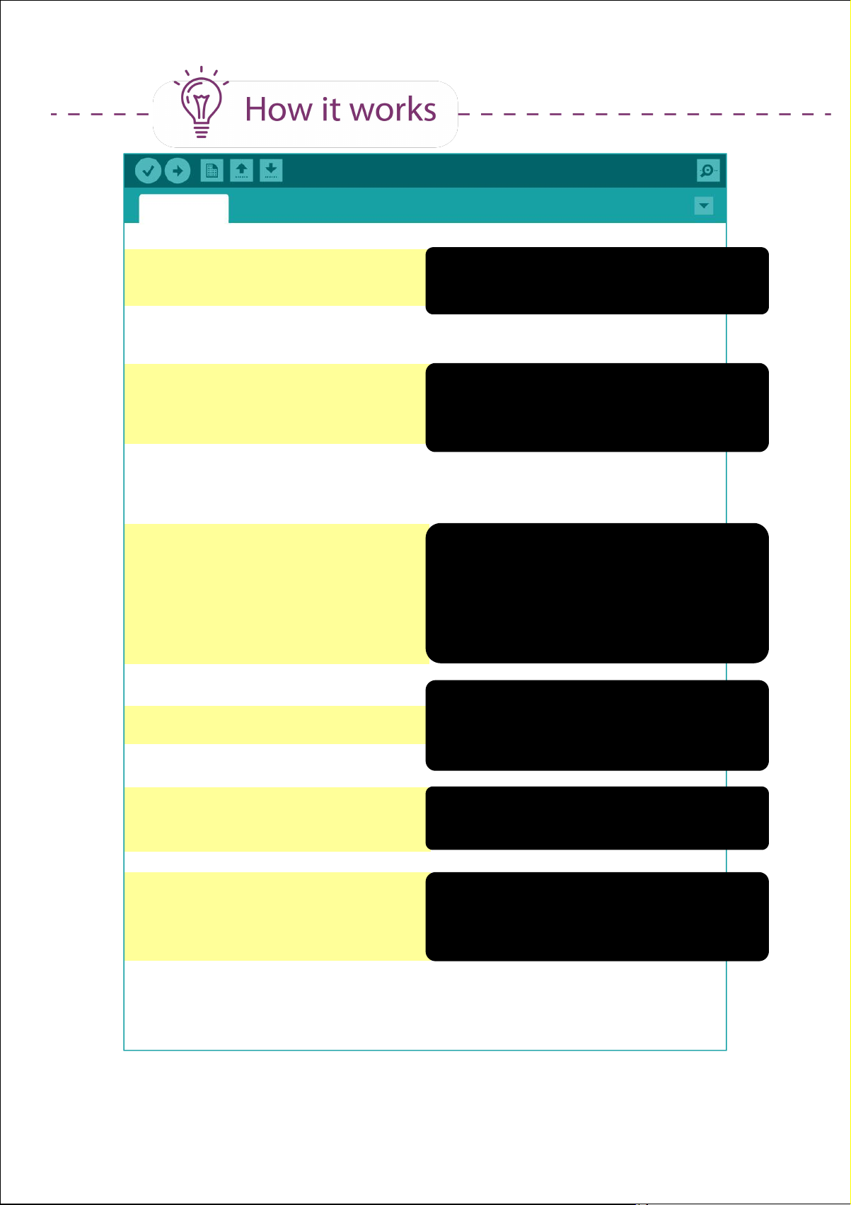
Project_16
long duration;
int distance;
void setup() {
pinMode(11, OUTPUT);
pinMode(12, INPUT);
Serial.begin (9600);
}
void loop() {
digitalWrite(11, LOW);
delayMicroseconds(2);
digitalWrite(11, HIGH);
delayMicroseconds(10);
digitalWrite(11, LOW);
Define “duration” as a long variable.
Define “distance” as an integer.
Set Pin 11 (trigger pin) as output.
Set Pin 12 (echo pin) as input.
Set up serial monitor (9600 baud)
Set Pin 11 (trigger pin) to low.
Delay for 2 microseconds.
Set Pin 11 to high (emit signal).
Delay for 10 microseconds.
Set Pin 11 to low again.
duration = pulseIn (12, HIGH);
distance = duration*0.034/2;
delay(50);
Serial.print (“Distance = “);
Serial.print (distance);
Serial.println (“cm “);
}
Check the pulse duration at Pin 12
(echo pin) and assign that value to
variable “duration”.
Convert that value of “duration” into
distance in cm. Hold for 50ms.
Print “Distance = “ in serial monitor
window, followed by “distance value”
and then “cm”.
92Simplifying Digital Making
Page 93
6. Next, let's modify your previous program into the following and then
upload to your board again.
Project_16a
long duration;
int distance;
void setup() {
pinMode(11, OUTPUT);
pinMode(12, INPUT);
Serial.begin (9600);
}
void loop() {
ultrasonic ();
Serial.print (“Distance = “);
Serial.print (distance);
Serial.println (“cm “);
}
void ultrasonic() {
digitalWrite(11, LOW);
delayMicroseconds(2);
digitalWrite(11, HIGH);
delayMicroseconds(10);
digitalWrite(11, LOW);
duration = pulseIn (12, HIGH);
distance = duration*0.034/2;
delay(50);
}
93Simplifying Digital Making
Page 94
7. Check your result.
Click here or scan
QR code to watch
the demo video.
You should get the same result as the
earlier program.
Project_16a
void loop() {
ultrasonic ();
Serial.print (“Distance = “);
Serial.print (distance);
Serial.println (“cm “);
}
void ultrasonic() {
digitalWrite(11, LOW);
delayMicroseconds(2);
digitalWrite(11, HIGH);
delayMicroseconds(10);
digitalWrite(11, LOW);
duration = pulseIn (12, HIGH);
Call the “ultrasonic” function (i.e.
execute all the lines of code in the
function “ultrasonic”.)
These lines of code have been
grouped into a function named
“ultrasonic”.
distance = duration*0.034/2;
delay(50);
}
94Simplifying Digital Making
Page 95
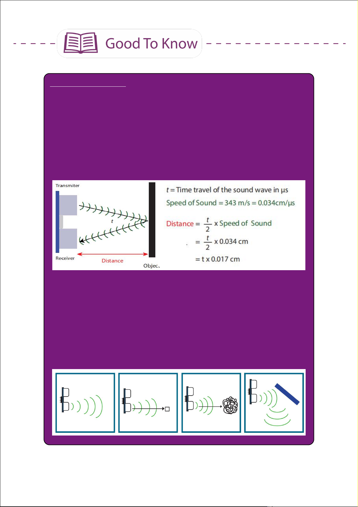
Ultrasonic Sensors
Like IR sensors, ultrasonic sensors are used to detect obstacles and
measure distances.The working mechanism is also similar to IR
sensors. The transmitter emits an ultrasonic wave, which upon hitting
an object in its path, is reflected back and detected by the receiver.
By calculating how long it takes for the reflected wave to be detected,
we can determine the distance of the object from the sensor.
Ultrasonic sensors are widely used as car reverse sensors to help
drivers to estimate distance and detect obstacles. The advantage of
an ultrasonic sensor over an infrared sensor is its insensitivity to the
surrounding lighting.
However, ultrasonic sensors may not work as expected if the object is
(i) too far away, (ii) too small, (iii) too soft or (iv) the object bounces
the sound wave away from the receiver.
(i) (ii) (iii) (iv)
95Simplifying Digital Making
Page 96

ARDUINO FUNCTION
Variable
Number Range
char
-128 to 127
int
-32,768 to 32,767
long
-2,147,483,648 to 2,147,483,647
float
3.4028235E+38 to 3.4028235E+38
1. You can use this function to read the time cycle of a pulse.
pulseIn (pin, value)
pin: the number of the pin on which you want to
read the pulse.
value: type of pulse to read; either HIGH or LOW
If the value is set to HIGH, pulseIn() waits for the pin to go from
LOW to HIGH, starts timing, then waits for the pin to go back to
LOW and stops timing. It returns the length of the pulse in
microseconds.
2. Data type
You may ask why most of the time we use “int” (integer) to define
a variable but in this project we are using “long” instead. This is
because we need to inform Arduino what kind of number we
want to store in the variable - whether it is a small number, a
large number, or a number with decimal points, etc. In this
project, the number we need to store for 'duration' is large.
96Simplifying Digital Making
Page 97
Project 17: Build a Car Rear Bumper Sensor
1. Modify your code in Project 16 to the following:
Project_17
long duration;
int distance;
void setup() {
pinMode(8, OUTPUT);
pinMode(11, OUTPUT);
pinMode(12, INPUT);
}
void loop() {
ultrasonic ();
if (distance < 2) {
tone(8, 349);
}
else {
tone (8, 349);
delay(50);
noTone(8);
delay(distance*10);
}
}
void ultrasonic() {
digitalWrite(11, LOW);
delayMicroseconds(2);
digitalWrite(11, HIGH);
delayMicroseconds(10);
digitalWrite(11, LOW);
duration = pulseIn (12, HIGH);
distance = duration*0.034/2;
delay(50);
}
97Simplifying Digital Making
Page 98
2. Upload the code to Maker UNO X and check your result.
Click here or scan
QR code to watch
the demo video.
Does the piezo buzzer beep repeatedly
when the sensor detects an obstacle?
Do you notice that the beeping intensifies
(i.e. the frequency of the beeping
increases) as the sensor is moved nearer
towards the object?
98Simplifying Digital Making
Page 99
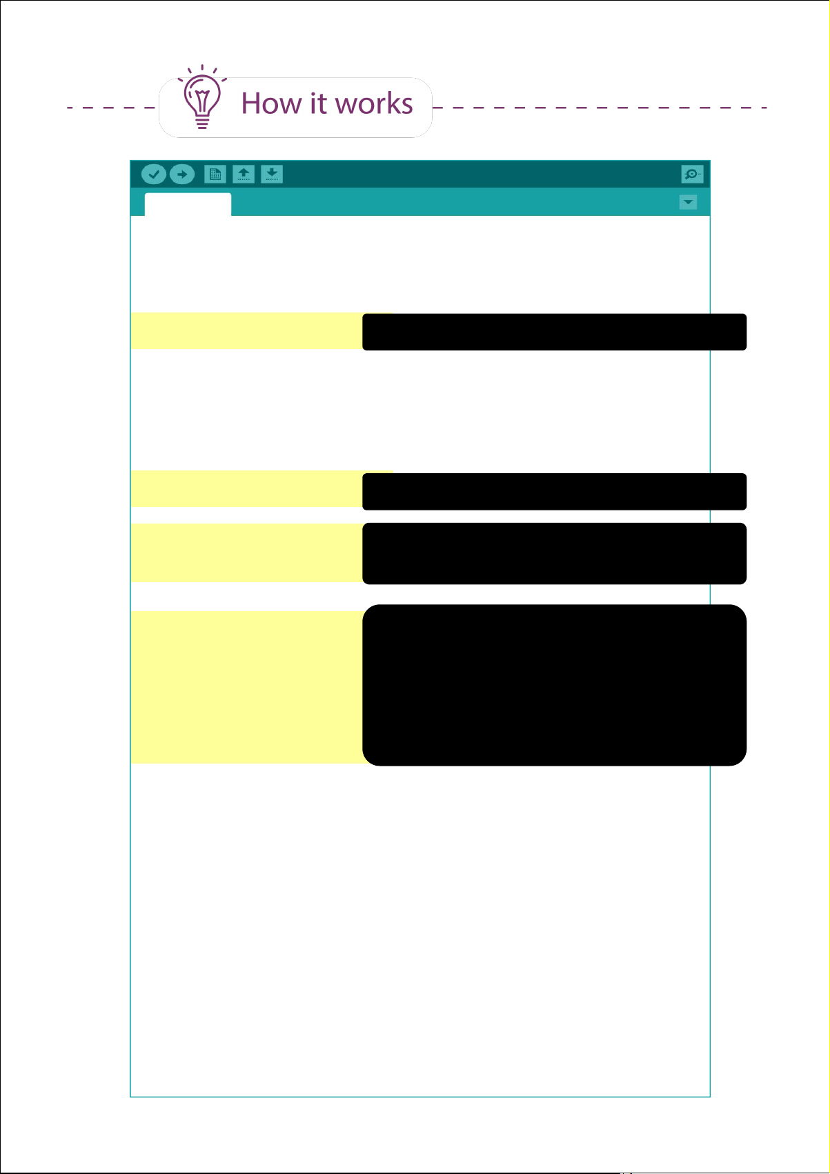
Project 17: Build a Car Rear Bumper Sensor
Project_17
long duration;
int distance;
void setup() {
pinMode(8, OUTPUT);
Set pin 8 (piezo buzzer) as output.
pinMode(11, OUTPUT);
pinMode(12, INPUT);
}
void loop() {
ultrasonic ();
if (distance < 2) {
tone(8, 349);
}
else {
tone (8, 349);
delay(50);
noTone(8);
delay(distance*10);
}
}
void ultrasonic() {
digitalWrite(11, LOW);
delayMicroseconds(2);
Call the “ultrasonic” function.
If distance is less than 2cm,
buzzer will play note F4 (349) continually.
Else, buzzer will beep note F4 (349) at
an interval of 'distance x 10' milliseconds.
E.g.: When distance = 5cm, the buzzer
beeps once every 50ms.
When distance = 10cm, the buzzer
beeps once every 100ms.
digitalWrite(11, HIGH);
delayMicroseconds(10);
digitalWrite(11, LOW);
duration = pulseIn (12, HIGH);
distance = duration*0.034/2;
delay(50);
}
99Simplifying Digital Making
Page 100
Do you know?
“The theremin is an electronic musical instrument controlled
without physical contact by the thereminist (performer). It is
named after its inventor, Léon Theremin, who patented the
device in 1928.”
Source: https://en.wikipedia.org/wiki/Theremin
Task: Build a Theremin using your Maker UNO X and the ultrasonic
sensor. Divide the ultrasonic sensor's sensing range into a few zones to
play different tones.
Click here or scan
QR code to watch
the demo video.
CONGRATULATIONS! You have completed Lesson 7 and learnt the
following:
Click here or scan
QR code to watch
a Theremin show.
1. How an ultrasonic sensor works.
2. How to create self-declared functions.
100Simplifying Digital Making
 Loading...