

Page 1

RS485 CAN HAT
1 / 24
RS485 CAN HAT
User Manual
OVERVIEW
The RS485 CAN HAT will enables your Pi to communicate with other devices stably in
long-distance via RS485/CAN functions.
FEATURES
⚫ Raspberry Pi connectivity, compatible with Raspberry Pi Zero/Zero W/Zero
WH/2B/3B/3B+
⚫ CAN function, onboard CAN controller MCP2515 via SPI interface, with transceiver
SN65HVD230
⚫ RS485 function, controlled via UART, half-duplex communication, with transceiver
SP3485
⚫ Reserved control pins, allows to work with other control boards
⚫ Comes with development resources and manual (examples in wiringPi/python)
SPECIFICATIONS
Operating voltage : 3.3V
CAN controller : MCP2515
Page 2

RS485 CAN HAT
2 / 24
CAN transceiver : SN65HVD230
485 transceiver : SP3485
Dimension : 65mm x 30mm
Mounting hole size : 3.0mm
INTERFACES
CAN:
PIN
Raspberry Pi
Description
3V3
3V3
3.3V Power
GND
GND
Ground
SCK
SCK
SPI Clock
MOSI
MOSI
SPI Data input
MISO
MISO
SPI Data output
CS
CE0
Data/Command selection
INT
PIN22 /GPIO.6/P25
Interrupt
RS485:
RSE pin could not be used because module is set to auto receiver and transmit in
hardware by default.
PIN
Raspberry Pi
Description
3V3
3V3
3.3V power
GND
GND
Ground
RXD
RXD
RS485 UART receive
TXD
TXD
RS485 UART transmit
RSE
PIN7/GPIO.7/P4
RS485 RX/TX setting
Page 3

RS485 CAN HAT
3 / 24
CONTENT
Overview....................................................................................................................................................... 1
Features ................................................................................................................................................ 1
Specifications ..................................................................................................................................... 1
Interfaces ............................................................................................................................................. 2
Hardware Description .............................................................................................................................. 5
CAN BUS .............................................................................................................................................. 5
RS485 BUS ........................................................................................................................................... 6
How to use .................................................................................................................................................. 9
Libraries installtion ........................................................................................................................... 9
CAN test ............................................................................................................................................. 10
Hardware ................................................................................................................................... 10
Preparation ............................................................................................................................... 10
C code example....................................................................................................................... 11
Python example ...................................................................................................................... 12
RS485 Test ......................................................................................................................................... 13
Hardware ................................................................................................................................... 13
Page 4

RS485 CAN HAT
4 / 24
Preparation ............................................................................................................................... 13
Python code ............................................................................................................................. 16
Code Analysis ........................................................................................................................................... 17
CAN ...................................................................................................................................................... 17
C code ......................................................................................................................................... 17
Python ........................................................................................................................................ 20
RS485 .................................................................................................................................................. 22
wiringPi code ........................................................................................................................... 22
Python code ............................................................................................................................. 24
Page 5
RS485 CAN HAT
5 / 24
HARDWARE DESCRIPTION
CAN BUS
CAN module could process packets transmit/receive on CAN bus. Packets
transmit: first store packet to related buffer and control register. Use SPI interface to
set the bits on control register or enable transmit pin for transmitting. Registers could
be read for detecting communication states and errors. It will first check if there are
any errors of packets detected on CAN bus, then verify it with filter which is defined by
user. And store packet to one of buffers if it has no errors.
Raspberry Pi cannot support SPI bus, so this module use SPI interface and on
board a receiver/transmitter for CAN communication.
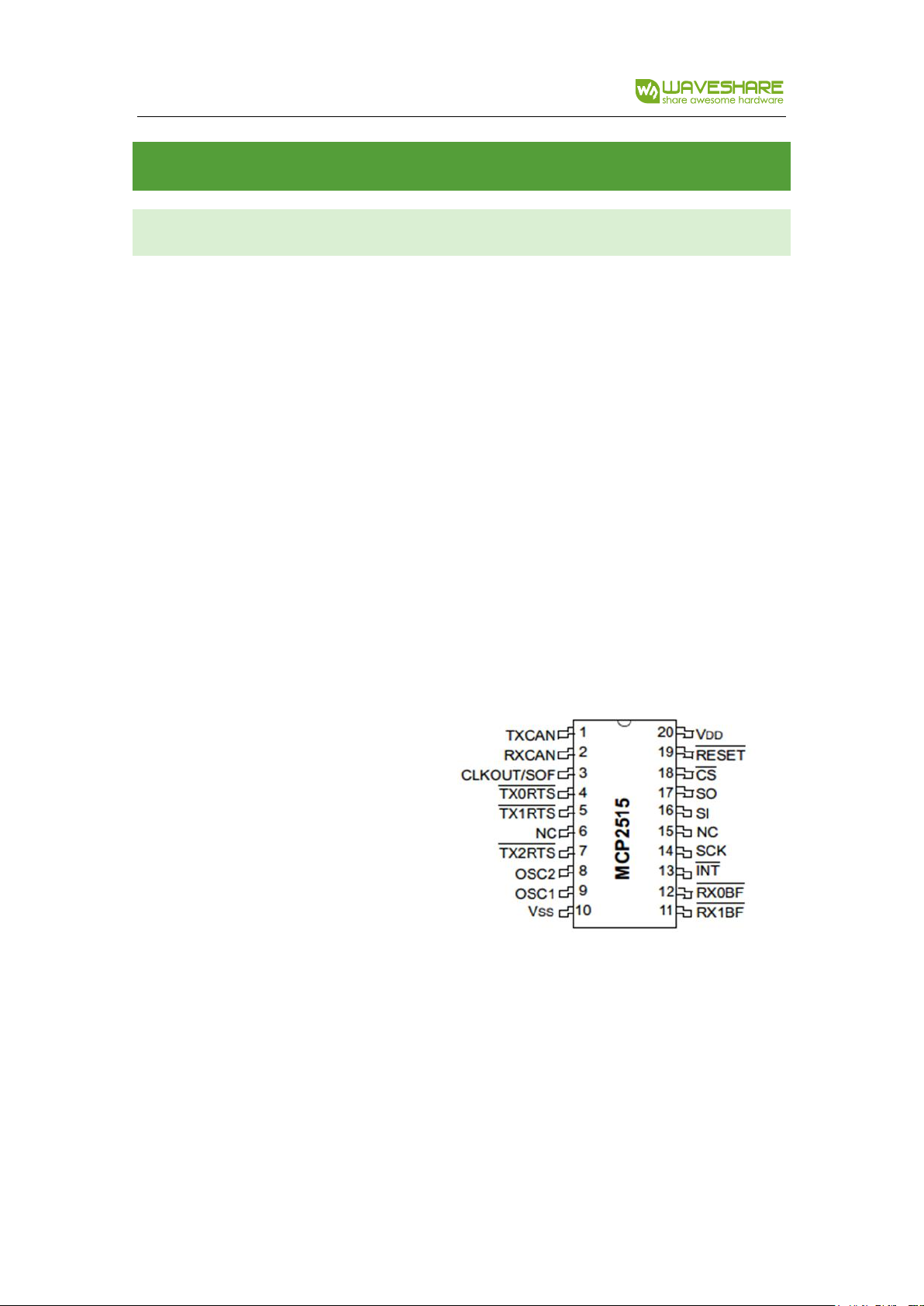
Microchip Technology’s
MCP2515 is a stand-alone Controller
Area Network (CAN) controller that
implements the CAN specification,
version 2.0B. It is capable of transmitting
and receiving both standard and
extended data and remote frames. The MCP2515 has two acceptance masks and six
acceptance filters that are used to filter out unwanted messages, thereby reducing the
host MCUs overhead. The MCP2515 interfaces with microcontrollers (MCUs) via an
industry standard Serial Peripheral Interface (SPI), that is Raspberry Pi can
Page 6
RS485 CAN HAT
6 / 24
communicate with MCP2515 via SPI interface without external driver. What we need to
do is to enable the kernel driver on devices tree.
For more details, please refer to datasheet.
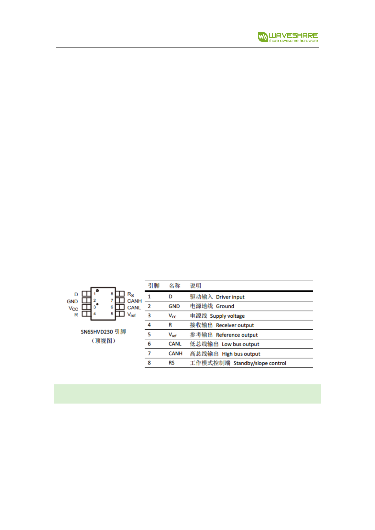
SN65HVD230 from TEXAS INSTRUMENTS is a CAN transceiver, which is designed
for high communication frequency, anti-jamming and high reliability CAN bus
communication. SN65HVD230 provide three different modes of operation: high-
speed, slope control and low-power modes. The operation mode can be controlled by
Rs pin. Connect the Tx of CAN controller to SN65HVD230’s data input pin D, can
transmit the data of CAN node to CAN network; And connect the RX of CAN controller
to SN65HVD230’s data input pin R to receive data.
RS485 BUS
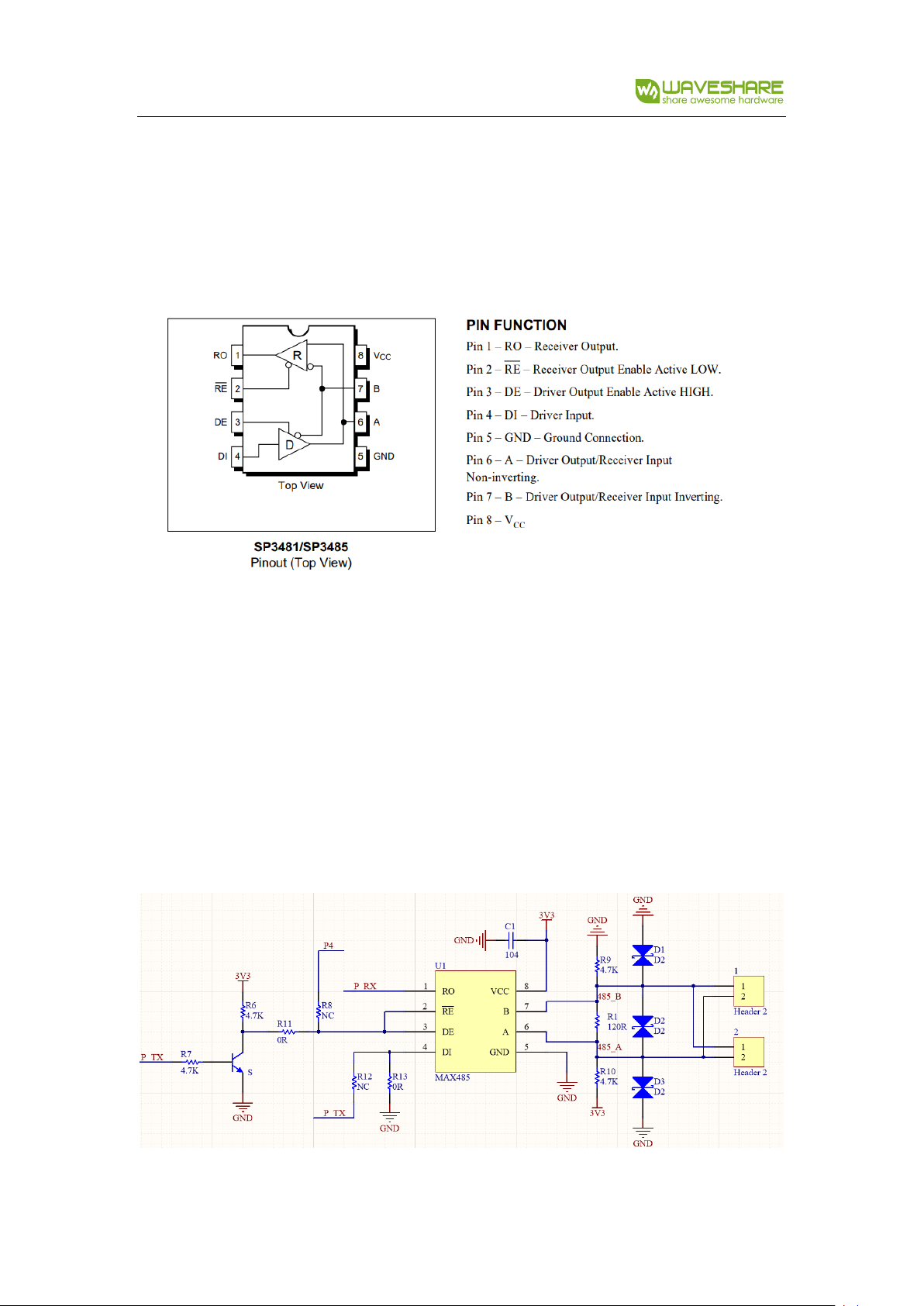
The SP3485 is a low power half-duplex transceiver that meet the specifications of
RS485 serial protocols. RO is Receiver output pin and DI is Driver input pin. RE is
Receiver Output Enable pin which is Active LOW and DE is Driver output Enable pin
Active HIGH. A is Driver Output/Receiver input non-inverting port and B is Driver
Page 7
RS485 CAN HAT
7 / 24
Output/Receiver input, Inverting port. When A-B >+0.2V, RO pin will output logic 1;
and when A-B<-0.2V, RO pin will output logic 0. 100Ω resistor is recommended to
add between A and B ports.
According to the hardware description, RE and DE pin of SP3845 are set to enable
receive and send.
This module is set to the way that hardware automatically receive/send, you can also
change to software receive/sending by changing the 0Ω resistors on board.
Hardware auto control:
Page 8

RS485 CAN HAT
8 / 24
Receiving data: P_TX is in idle state, which is high level, transistor breakover, RE pin of
SP3485 is low to be active. RO pin begins to receive data from 485AB port.
Sending data: P_TX will get a pull-down level, toggle that sending data. Transistor cut
off, DE pin is high to enable sending. In sending states, if the data sent is “1”,
transistor will turn to breakover which looks like Receiving states, however, the chip is
in high impedance sate, data “1” will still be sending instead of changing to
receiving.
Page 9
RS485 CAN HAT
9 / 24
HOW TO USE
LIBRARIES INSTALLTION
To use the demo codes, you should install libraries (wiringPi, bcm2835, python) first,
otherwise the codes cannot work properly. About how to install libraries, you can refer
to Wiki page:
https://www.waveshare.com/wiki/Libraries_Installation_for_RPi
For python, you should install two more libraries as below:
sudo apt-get install python-pip
sudo pip install python-can
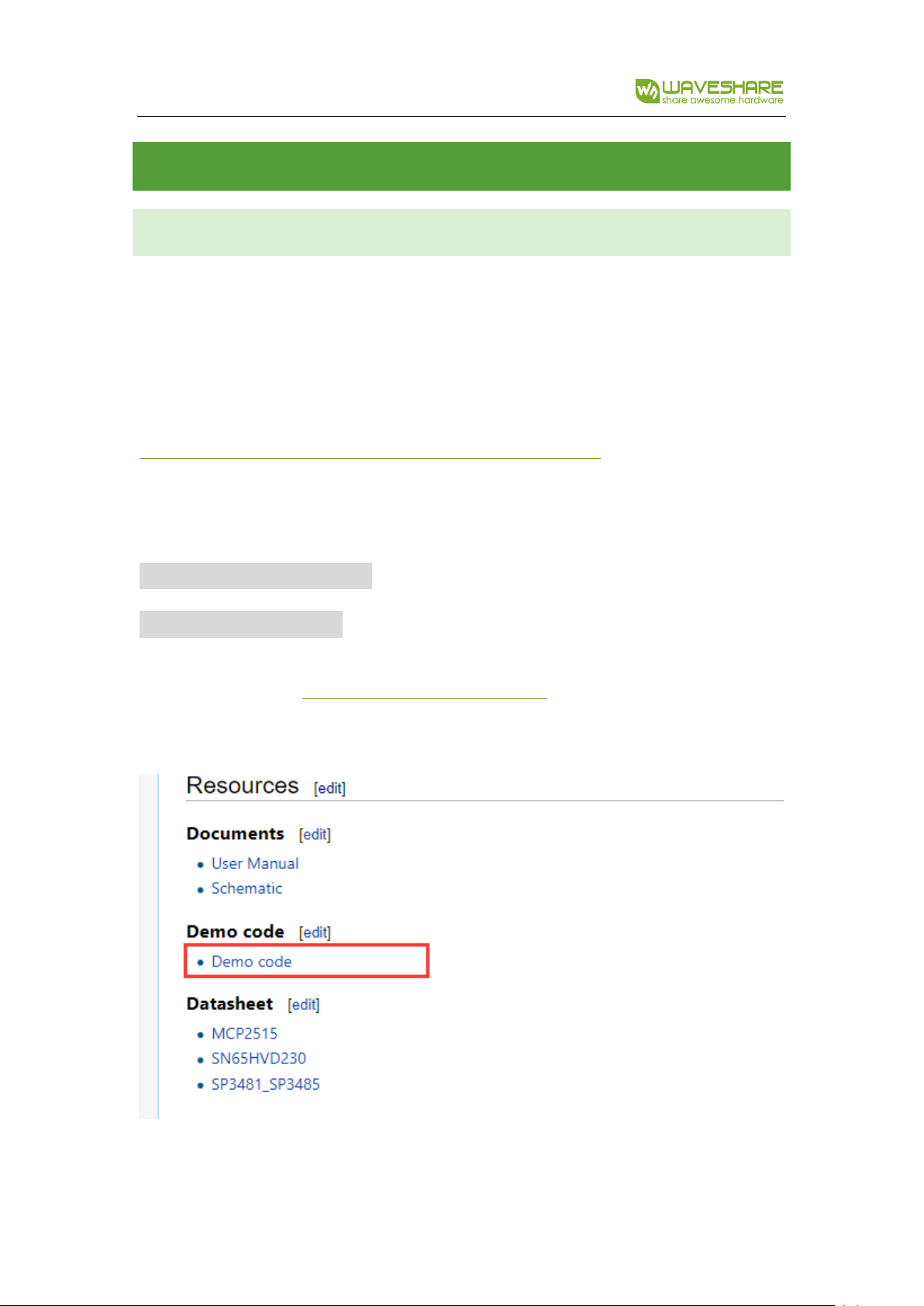
Visit Waveshare Wiki: https://www.waveshare.com/wiki and search with “RS485 CAN
CAPE”, download the demo code.
Decompressed and copy to Raspberry Pi.
Page 10
RS485 CAN HAT
10 / 24
CAN TEST
HARDWARE
Raspberry Pi 3B x2
Waveshare RS485 CAN HAT x2
PREPARATION
1. Insert RS485 CAN HAT to Raspberry Pi, and then modify config.txt file:
sudo vi /boot/config.txt
2. Append these statements to the file:
dtparam=spi=on
dtoverlay=mcp2515-can0,oscillator=8000000,interrupt=25,spimaxfrequency=1000000
3. Save and exit, then restart your Pi.
sudo reboot
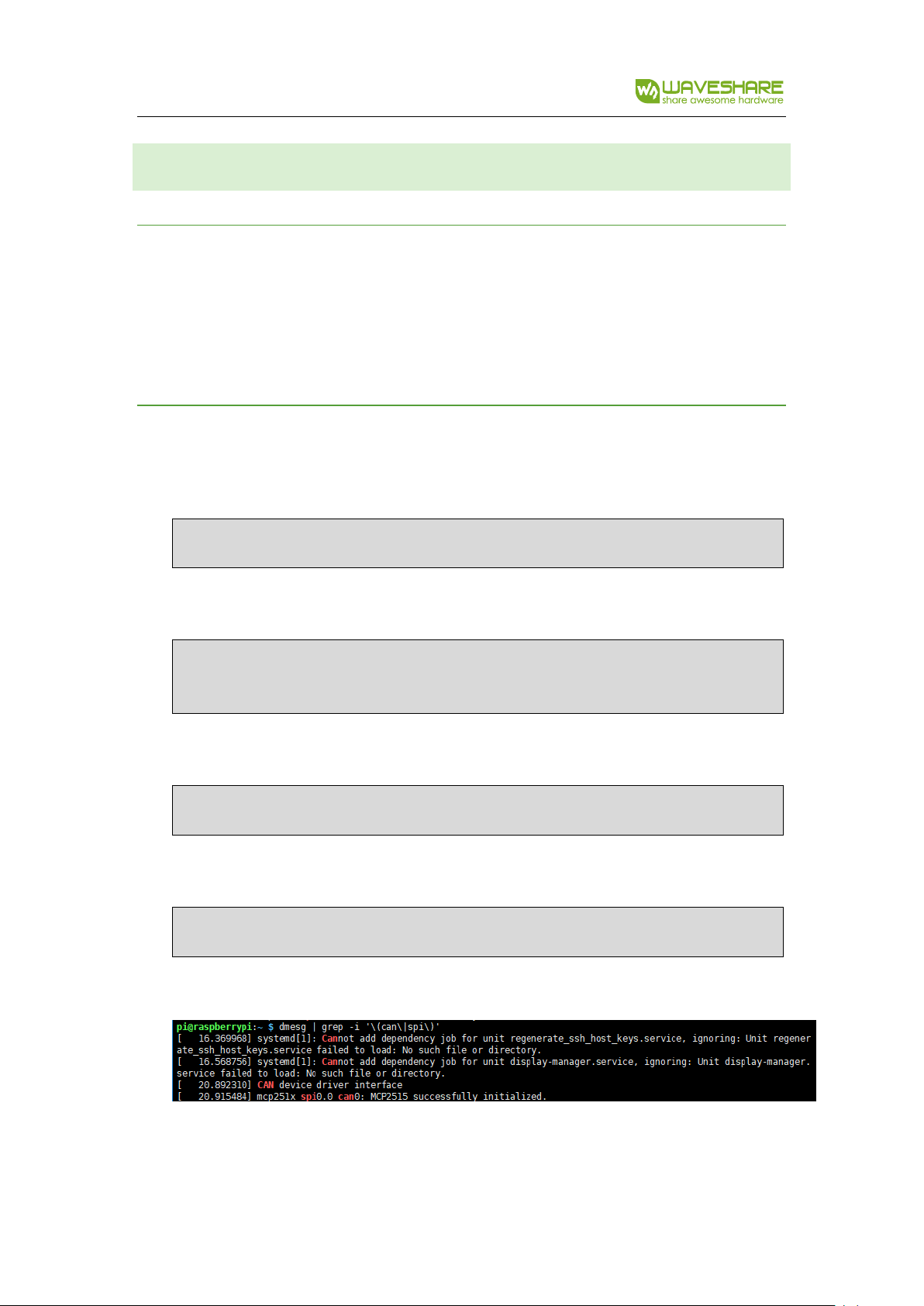
4. After restart, check if initialize successfully:
dmesg | grep -i '\(can\|spi\)'
It will print information as below:
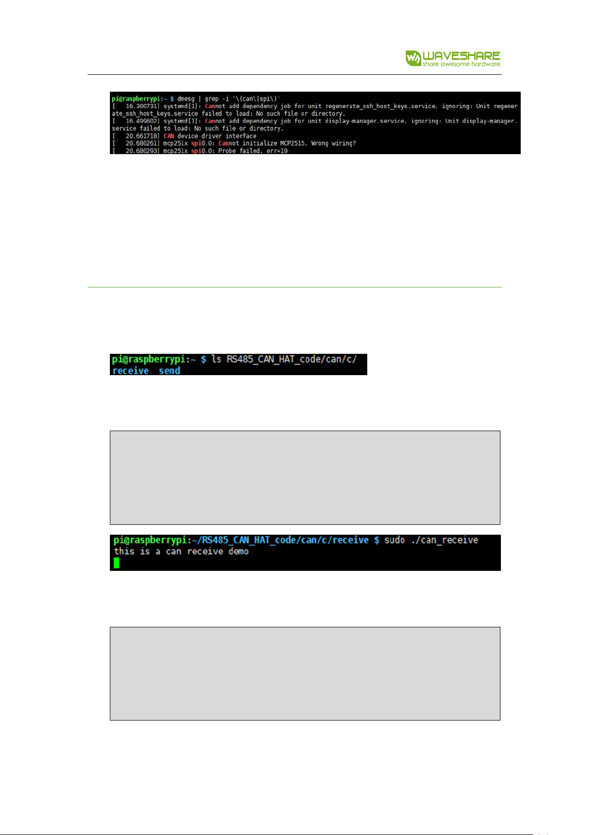
The information will be different if RAS485 CAN HAT doesn’t be inserted:
Page 11
RS485 CAN HAT
11 / 24
In this case, you need to check if the module is connected? If SPI interface and
CP2515 kernel driver is enable and restart Raspberry Pi.
5. Connect the H and L port of RS485 CAN HAT to another’s.
C CODE EXAMPLE
1. List the folder of demo code you can get as below:
2. Set one HAT as receiver: Enter the directory of receiver and run the code
cd /RS485_CAN_HAT_code/can/c/receive
make
sudo ./can_receive
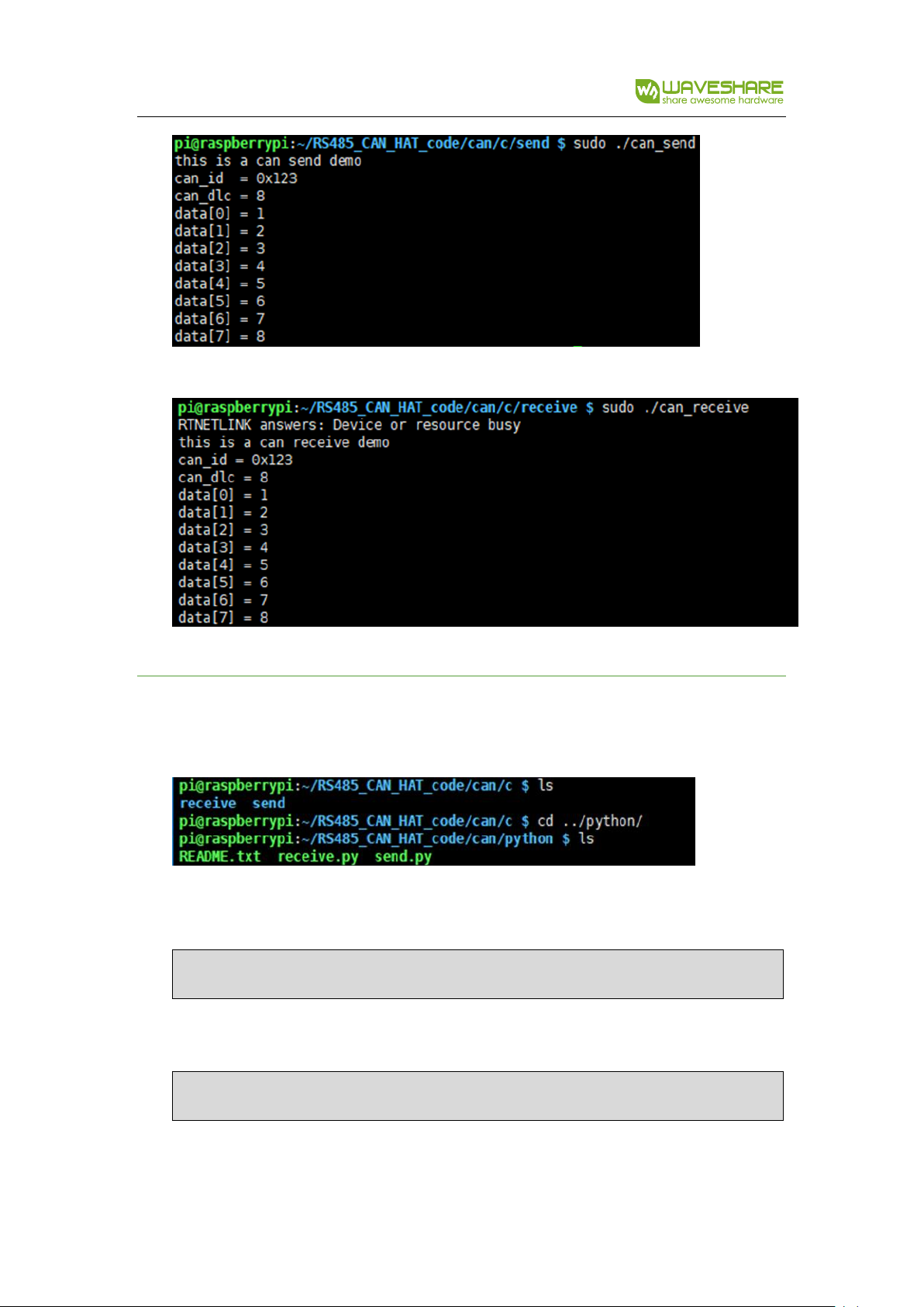
3. Set another as Sender: Enter the directory of send and run the code
cd /RS485_CAN_HAT_code/can/c/send
make
sudo ./can_send
Page 12
RS485 CAN HAT
12 / 24
At the same time you can find the receiver receive the packet from sender:
PYTHON EXAMPLE
1. List the folder:
2. Set the receiver first:
sudo python can_reveive.py
3. Then the sender:
sudo python can_send.py
Page 13
RS485 CAN HAT
13 / 24
RS485 TEST
HARDWARE
Raspberry Pi 3B x2
RS485 CAN HAT x2
PREPARATION
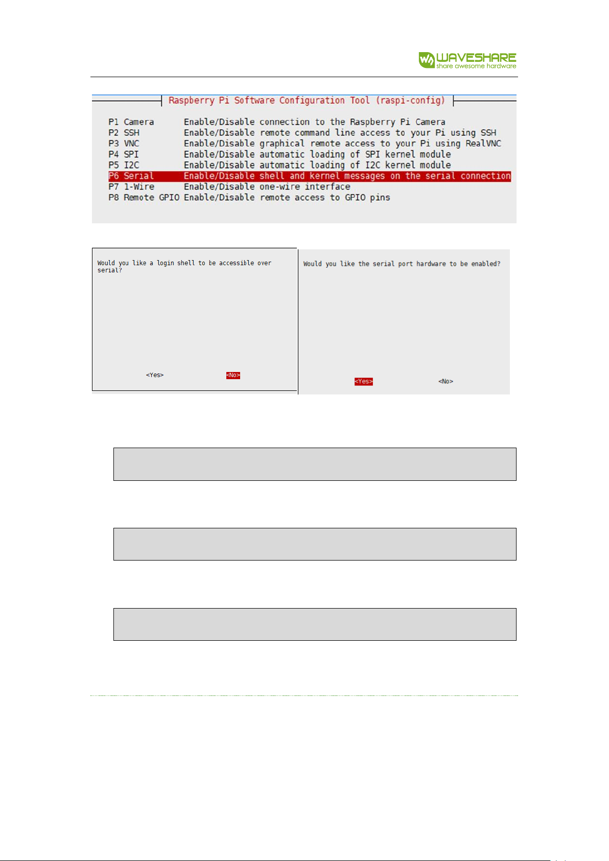
The serial of Raspberry Pi is used for Linux console output by default, so we need to
disable it first:
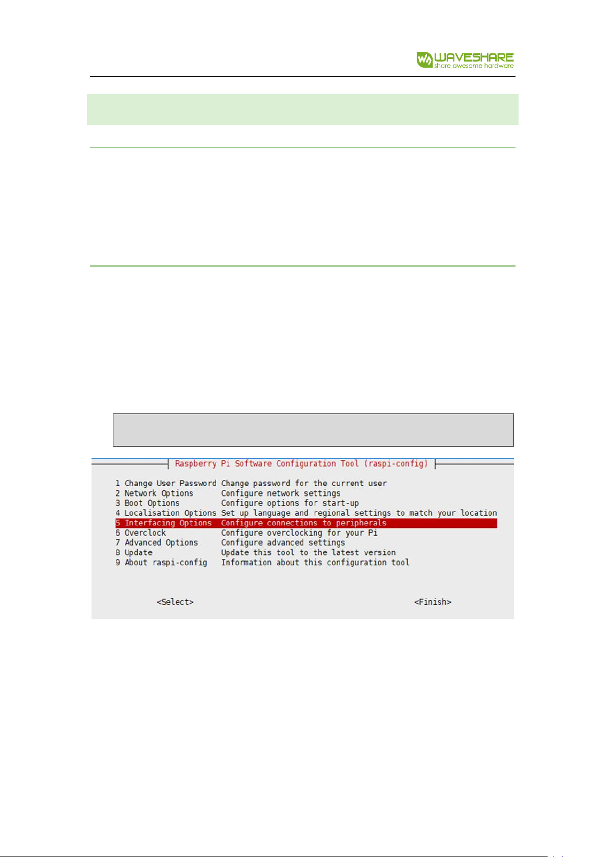
1. Run command to open raspi-config:
sudo raspi-config
2. Choose Interfaces Options ->Serial->no
Page 14
RS485 CAN HAT
14 / 24
3. Open file /boot/config.txt, add the statement to the end:
enable_uart=1
4. For Raspberry Pi, the serial port is used for Bluetooth, which should be commend:
#dtoverlay=pi-minuart-bt
5. reboot Raspberry Pi
sudo reboot
6. Connect A and B port of HAT to another’s
WIRINGPI CODE
Page 15
RS485 CAN HAT
15 / 24
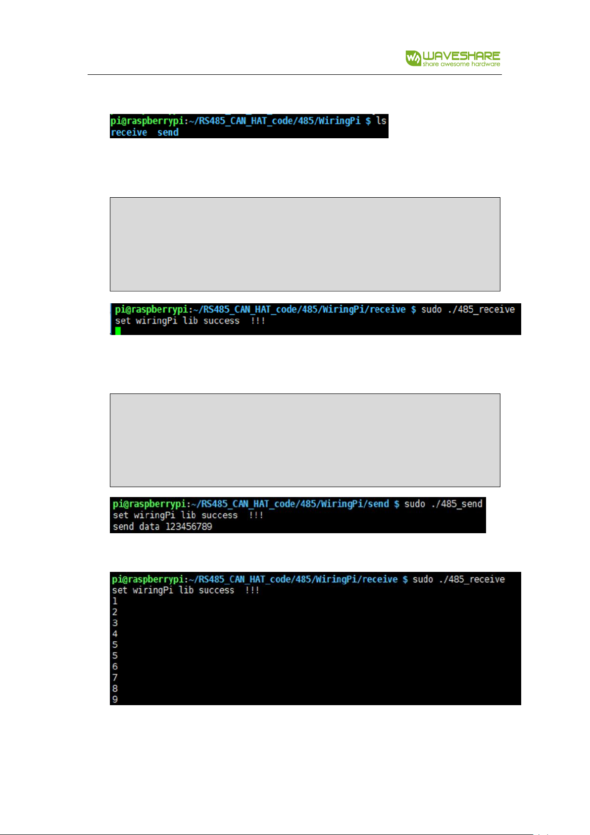
1. List folders:
2. Set receiver:
cd /RS485_CAN_HAT_code/can/c/receive
make
sudo ./can_receive
3. Set sender:
cd /RS485_CAN_HAT_code/can/c/send
make
sudo ./can_send
The packet received at receiver is as below:
Page 16
RS485 CAN HAT
16 / 24
PYTHON CODE
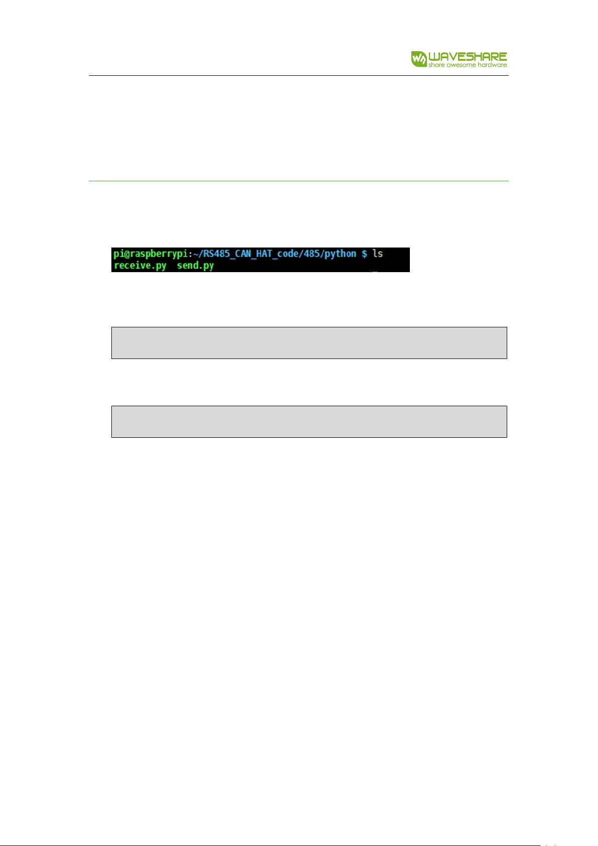
1. List folders:
2. First set receiver:
sudo python reveive.py
3. Set sender:
sudo python send.py
Page 17

RS485 CAN HAT
17 / 24
CODE ANALYSIS
CAN
We provide two codes for CAN communication, one is C code and another is python.
C code use socket-can and python use similar libraries as well.
C CODE
This example uses socket skill similar to network coding skill of Linux. If you have
studied Linux network coding, you will familiar to it: Socketcan is method for CAN
protocol in Linux.
Step 1: Open socket
s = socket(PF_CAN, SOCK_RAW, CAN_RAW);
if it failed it will return -1
Step 2: Target device can0
strcpy(ifr.ifr_name, "can0");
ret = ioctl(s, SIOCGIFINDEX, &ifr);
Step 3: Bind socket to CAN interface.
addr.can_family = AF_CAN;
addr.can_ifindex = ifr.ifr_ifindex;
ret = bind(s, (struct sockaddr *)&addr, sizeof(addr));
Page 18

RS485 CAN HAT
18 / 24
Step 4: Set rule that only send
setsockopt(s, SOL_CAN_RAW, CAN_RAW_FILTER, NULL, 0);
Step 5: Set the data
struct can_frame frame;
frame.can_id = 0x123;
frame.can_dlc = 8;
frame.data[0] = 1;
frame.data[1] = 2;
frame.data[2] = 3;
frame.data[3] = 4;
frame.data[4] = 5;
frame.data[5] = 6;
frame.data[6] = 7;
frame.data[7] = 8;
Step 6: Transmit data
nbytes = write(s, &frame, sizeof(frame));
Calling write() function to write the data to socket, it will return-1 if failed and return
the number of byte if success. We could use the return value to check if it is
successfully sending.
if(nbytes != sizeof(frame)) {
Page 19

RS485 CAN HAT
19 / 24
printf("Send Error frame[0]!\r\n");
system("sudo ifconfig can0 down");
}
Step 7: Close socket and CAN device
close(s);
system("sudo ifconfig can0 down");
Note: if you dont close CAN device, system will prompt CAN bus is busy at next
sending.
For Receiving:
1. It is different when binding socket
addr.can_family = PF_CAN;
addr.can_ifindex = ifr.ifr_ifindex;
ret = bind(s, (struct sockaddr *)&addr, sizeof(addr));
if (ret < 0) {
perror("bind failed");
return 1;
}
2. The receive could be defined to only receive socket whose ID is 0x123
struct can_filter rfilter[1];
Page 20

RS485 CAN HAT
20 / 24
rfilter[0].can_id = 0x123;
rfilter[0].can_mask = CAN_SFF_MASK;
setsockopt(s, SOL_CAN_RAW, CAN_RAW_FILTER, &rfilter, sizeof(rfilter));
3. Read data read()
nbytes = read(s, &frame, sizeof(frame));
Return number of bytes it read.
For more information about socket-can coding please refer:
https://www.kernel.org/doc/Documentation/networking/can.txt
PYTHON
Before use python sample, check if python-can library has been installed
Build up CAN device first:
os.system('sudo ip link set can0 type can bitrate 100000')
os.system('sudo ifconfig can0 up')
Step 1: Connect to CAN bus
can0 = can.interface.Bus(channel = 'can0', bustype = 'socketcan_ctypes')# socketcan_native
Step2: Create message
msg = can.Message(arbitration_id=0x123, data=[0, 1, 2, 3, 4, 5, 6, 7], extended_id=False)
Step 3: Send message
Page 21

RS485 CAN HAT
21 / 24
can0.send(msg)
Step 4: Finial close device as well
os.system('sudo ifconfig can0 down')
Receive Data:
msg = can0.recv(10.0)
recv() define the timeout of receiving.
For more information please refer to:
https://python-can.readthedocs.io/en/stable/interfaces/socketcan.html
Page 22

RS485 CAN HAT
22 / 24
RS485
For RS485 communication, we provide two sample code, one is based on wiringPi
library and another is Python.
WIRINGPI CODE
Steps 1: Set Receiving and sending
The RE and DE pin of SP3485 are used for enable input and output (Chapter
Hardware description).
#define EN_485 18
if(wiringPiSetupGpio() < 0) { //use BCM2835 Pin number table
printf("set wiringPi lib failed !!! \r\n");
return -1;
} else {
printf("set wiringPi lib success !!! \r\n");
}
pinMode(EN_485, OUTPUT);
digitalWrite(EN_485,HIGH);
The example code sets module to sending states. the Pin18 is the ID based on
bcm2835 libraries. For wiringPi, the pin id of bcm2835 is workable as well as wiringpi
pin id. wiringPiSetupGpio() is called for using bcm2835 pin id and wiringPiSetup()
called for using wiringPi pin id.
Page 23

RS485 CAN HAT
23 / 24
Step 2: Create file descriptor, open serial /dev/ttyS0 and set baudrate
if((fd = serialOpen ("/dev/ttyS0",9600)) < 0) {
printf("serial err\n");
return -1;
}
Step 3: Send data
serialFlush(fd);
serialPrintf(fd,"\r");
serialPuts(fd, "12345");
serialFlush() #clean all data on serial and wait for sending
serialPrintf() #similar to printf function, bind the tansmit datato file desriptor
serialPuts() #Send string which end with nul to serial device marked by related file
descriptor
The serialGetchar(fd) function will return a character which is should used next of
serial device, it will cause some wrong errors, so the sender should send a character
“\r” to avoid this phenomenon. (If you have better way, kindly to contact us)
For more information about functions, please refer to:
http://wiringpi.com/reference/serial-library/
Page 24
RS485 CAN HAT
24 / 24
PYTHON CODE
Using Python to control RS485 will be much easy. Python could operate serial directly:
Open serial file and set the baud rate as well.
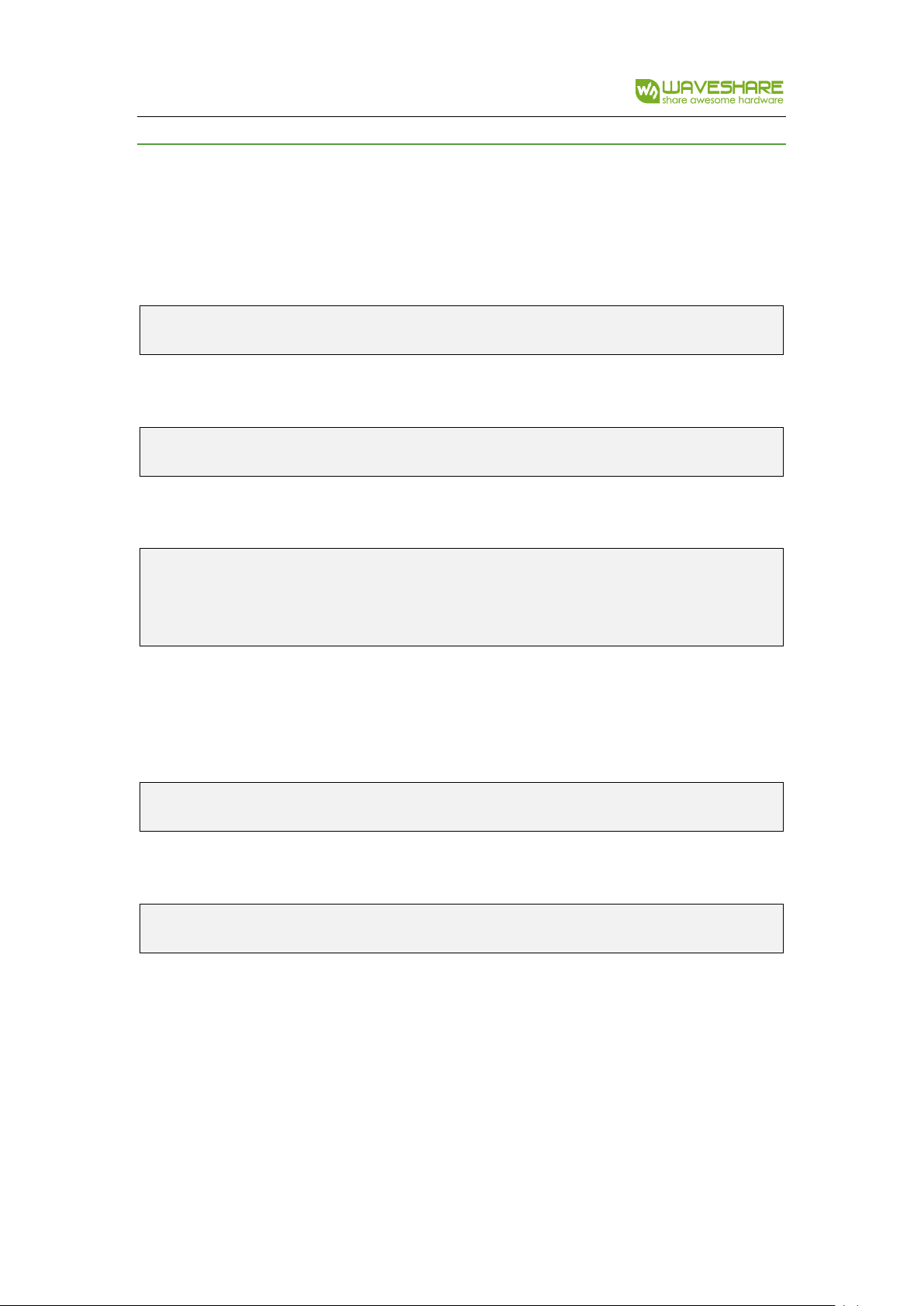
t = serial.Serial("/dev/ttyS0",115200)
Set the command which you want to send:
command = ["a","b","c",",","1","5",0x24,0x48]
Write the data to serial, and it will response the numbers of bytes written:
len = ser.write(command)
print("len:"),len
Reading:
Return the number of bytes in buffer:
ser.inWaiting()
Read data (length is definable):
ser.read(ser.inWaiting())
 Loading...