

Page 1
ROBOT . HEAD to TOE
Product User’s Manual – HAT-MDD10
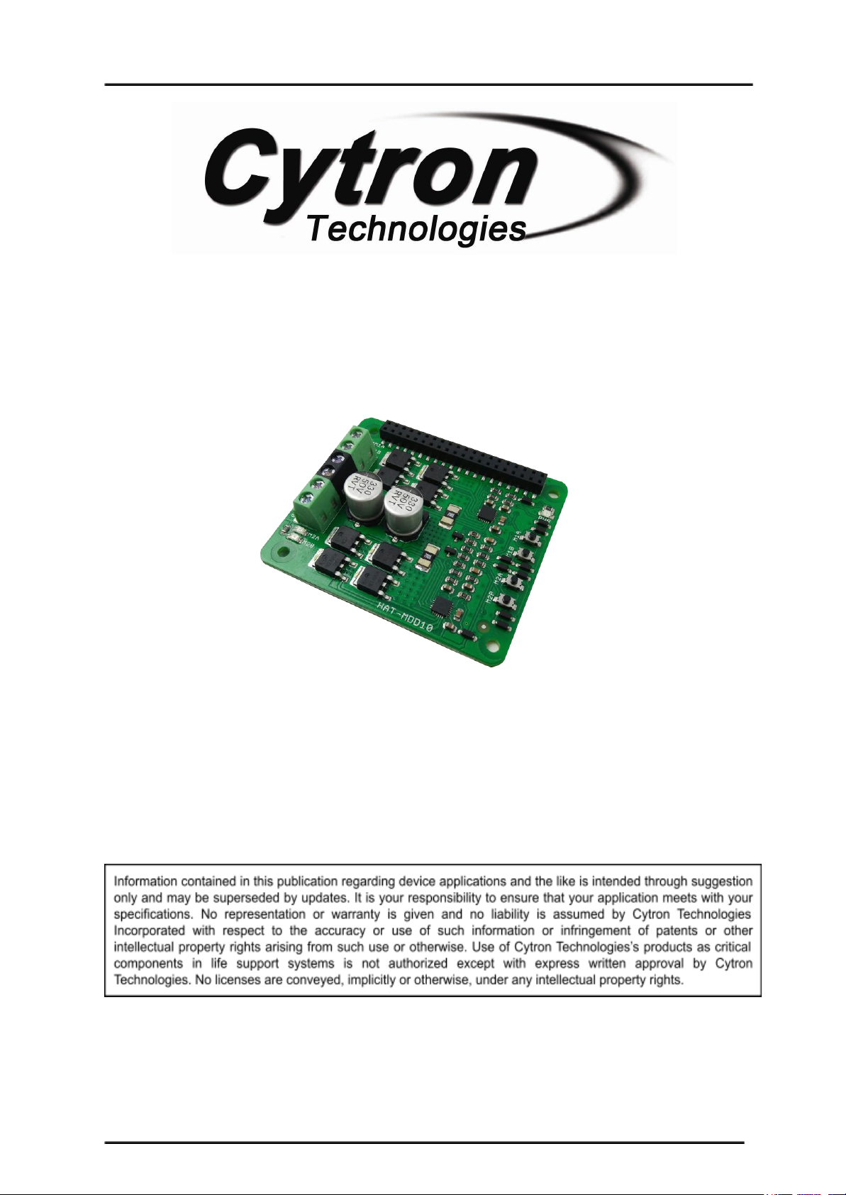
HAT-MDD10
10Amp DC Motor Driver for
Raspberry Pi
User's Manual
V1.0
Mac 2017
Created by Cytron Technologies Sdn. Bhd. – All Rights Reserved 1
Page 2

ROBOT . HEAD to TOE
Product User’s Manual – HAT-MDD10
INDEX
1. Introduction/Overview 3
2. Packing List 4
3. Board Layout 5
4. Product Specification 8
5. Dimension 9
6. Getting Started 10
7. Warranty 11
Created by Cytron Technologies Sdn. Bhd. – All Rights Reserved 2
Page 3

ROBOT . HEAD to TOE
Product User’s Manual – HAT-MDD10
1. INTRODUCTION/OVERVIEW
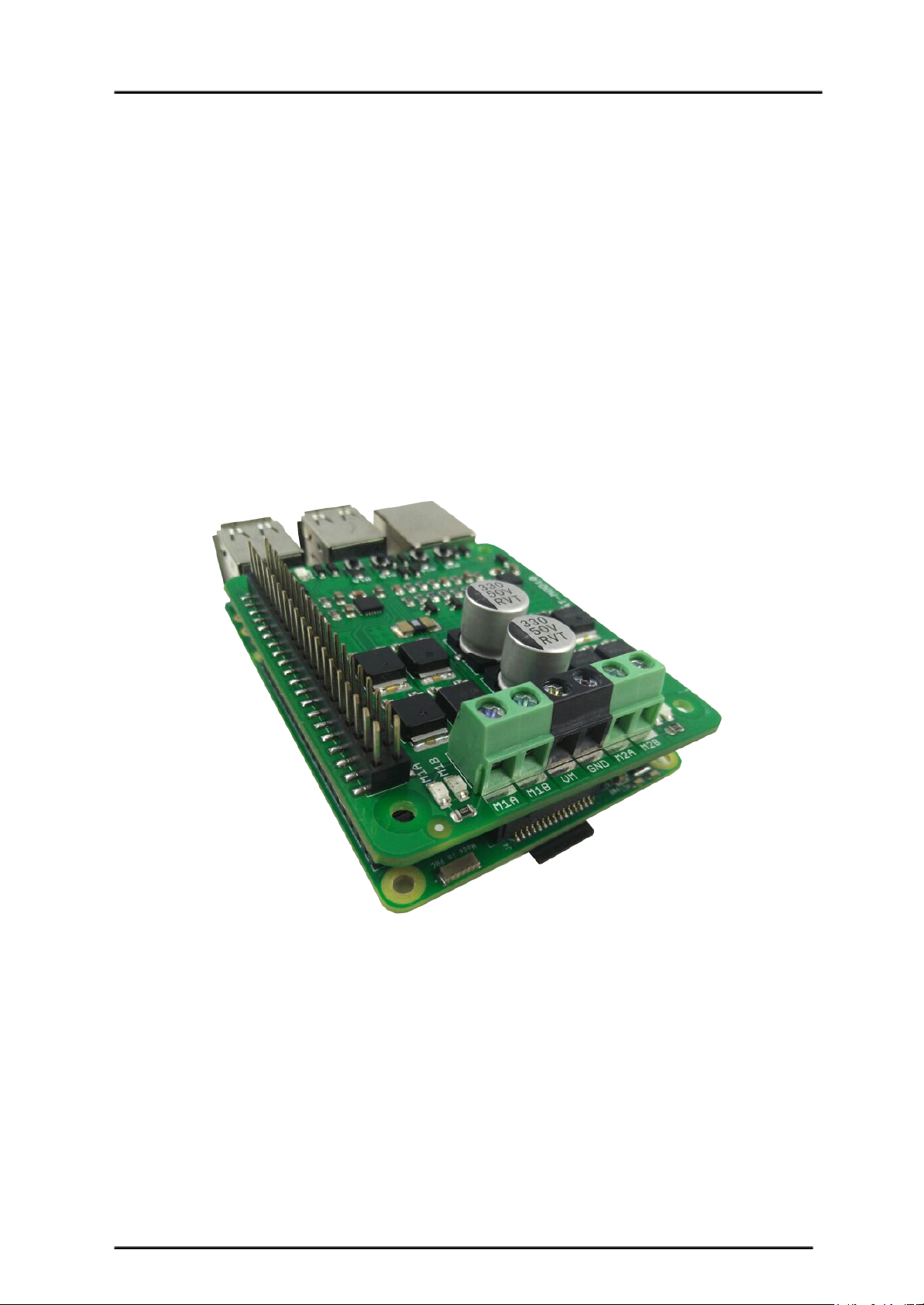
HAT-MDD10 is designed to drive two high current brushed DC motor up to 10A
continuously by using Raspberry Pi as a controller. It offers several enhancements such as
support for both locked-antiphase and sign-magnitude PWM signal as well as using full solid
state components which result in faster response time and eliminate the wear and tear of the
mechanical relay.
The HAT-MDD10 has been designed with the capabilities and features of:
● Bi-directional control for two brushed DC motor.
● Support motor voltage ranges from 6V to 24V.
● Maximum current up to 10A continuous (without heatsink at 25℃) and 30A peak (10
second).
● Current limiting at 30A.
● 3.3V and 5V logic level input.
● Raspberry Pi compatible connector.
● Manual/test button to fast verification.
● Solid state components provide faster response time and eliminate the wear and tear
of mechanical relay.
● Fully NMOS H-Bridge for better efficiency and no heat sink is required.
● Speed control PWM frequency up to 20KHz (Actual output frequency is same as
input frequency).
● Support both locked-antiphase and sign-magnitude PWM operation.
● Support TTL PWM from microcontroller, not PWM from RC receiver.
● Dimension:67.5mm x 59mm
Created by Cytron Technologies Sdn. Bhd. – All Rights Reserved 3
Page 4
ROBOT . HEAD to TOE
Product User’s Manual – HAT-MDD10
2. PACKING LIST
Please check the parts and components according to the packing list. If there are any parts
missing, please contact us at [email protected] immediately.
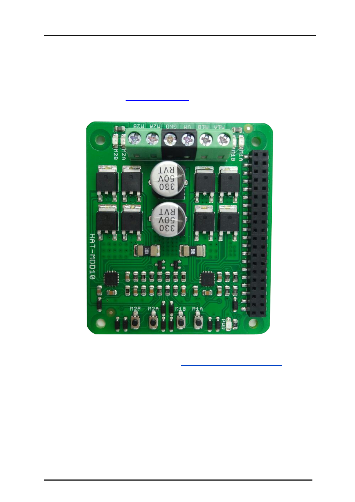
1. 1 x Hat-MDD10 10A DC Motor Driver.
2. 1 x PC104 Header Pin (2x20) (CN-PH-PC104)
3. User’s manual can be downloaded from https://www.cytron.io/p-hat-mdd10
Created by Cytron Technologies Sdn. Bhd. – All Rights Reserved 4
Page 5
ROBOT . HEAD to TOE
Product User’s Manual – HAT-MDD10
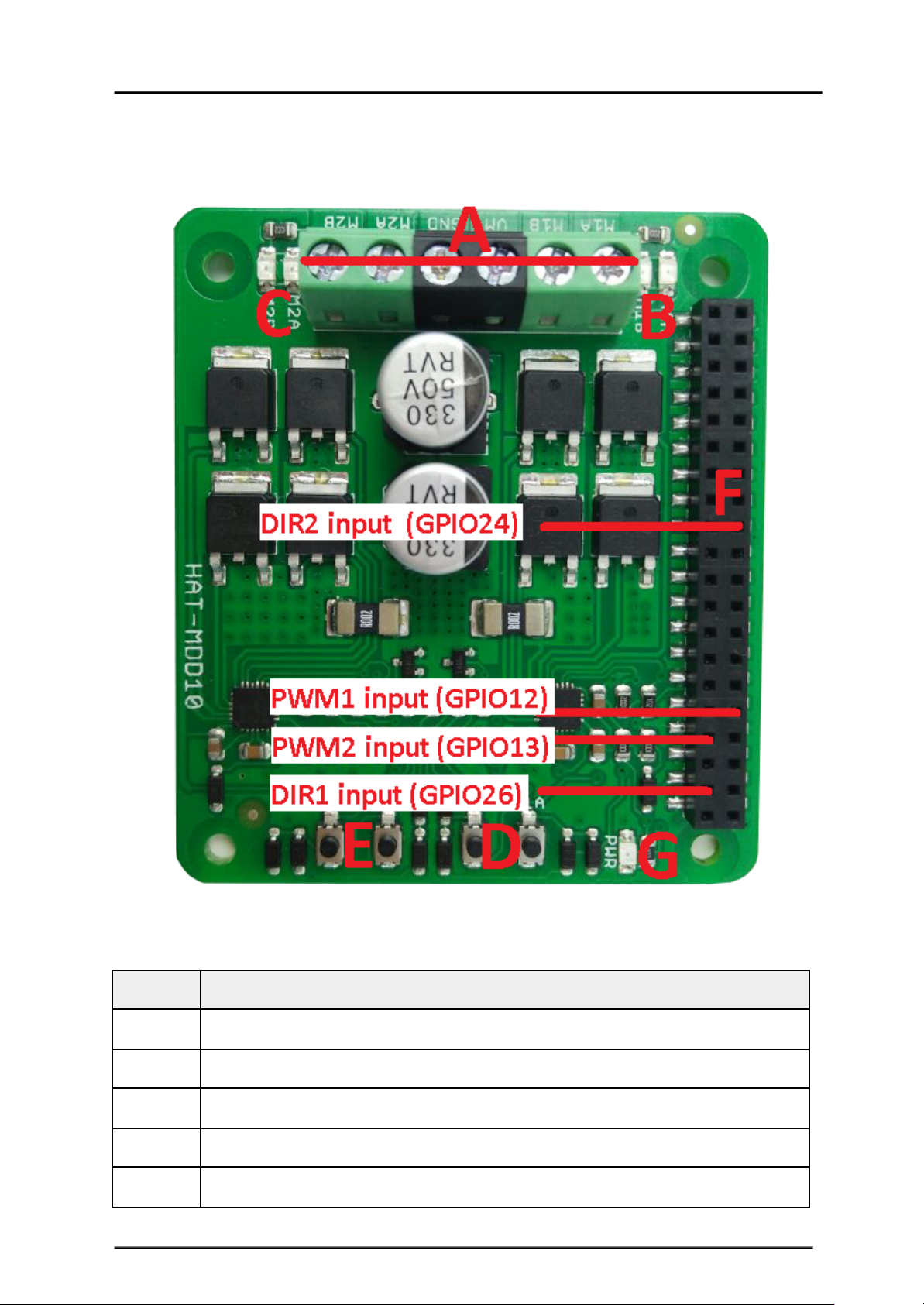
3. BOARD LAYOUT AND SPECIFICATION
Label
Function
A
Terminal Block
B
Motor1 LED Indicator
C
Motor2 LED Indicator
D
Motor1 Test Switch
E
Motor2 Test Switch
Created by Cytron Technologies Sdn. Bhd. – All Rights Reserved 5
Page 6
ROBOT . HEAD to TOE
Product User’s Manual – HAT-MDD10
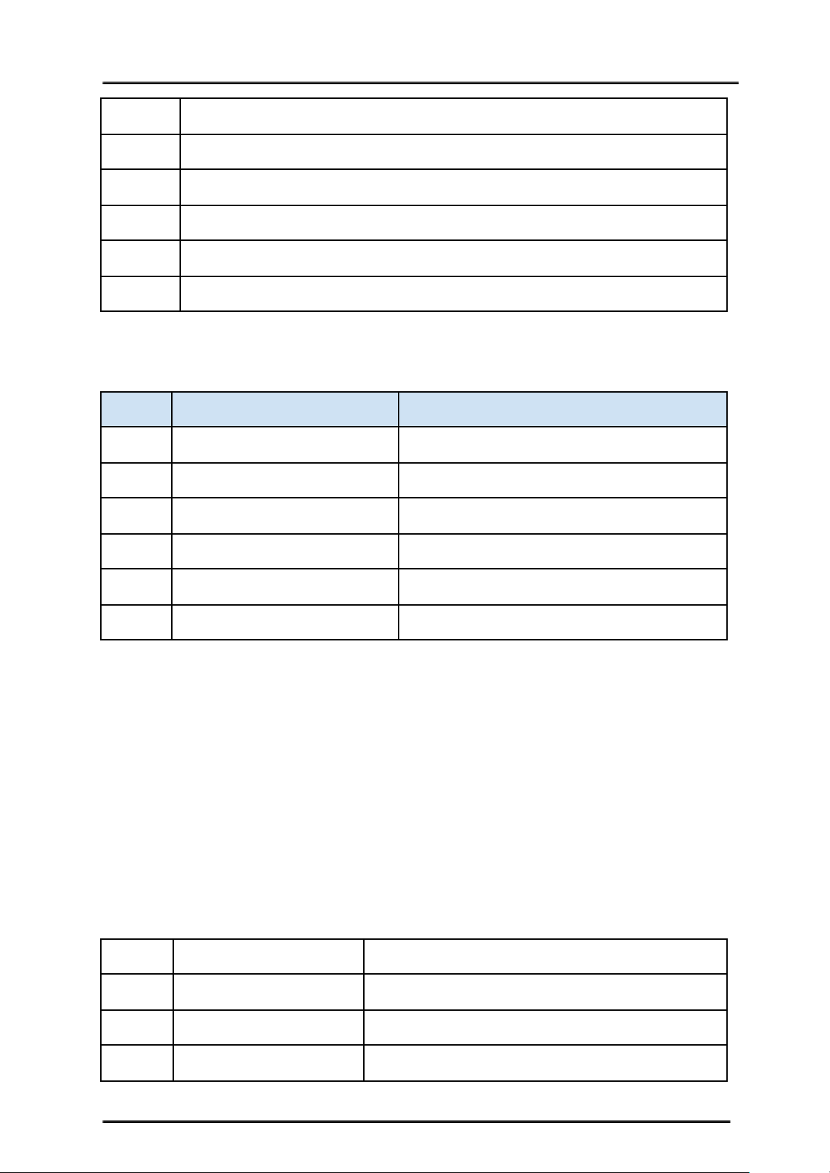
F
Raspberry Pie Connector
G
Power LED Indicator
H
PWM1 input (GPIO12)
I
DIR1 input (GPIO26)
J
PWM2 input (GPIO13)
K
DIR2 input (GPIO24)
1. Terminal Block – Connect to motor and power source.
Pin Name
Description
1
M1A
Connect to motor1 terminal A
2
M1B
Connect to motor1 terminal B
3
VM
Positive Supply (6V to 24V*1)
4
GND
Negative Supply
5
M2A
Connect to motor2 terminal A
6
M2B
Connect to motor2 terminal B
*1: Absolute Maximum
2. M1A/M2A LED Indicator – Turns on when the output A is high and output B is low.
Indicates the current flows from output A to B.
3. M1B/M2B LED Indicator – Turns on when the output A is low and output B is high.
Indicates the current flows from output B to A.
4. M1A/M2A Test Switch – When this button is pressed, current flows from output A to B
and motor will turn CW (or CCW depending on the connection).
5. M1B/M2B Test Switch – When this button is pressed, current flows from output B to A
and motor will turn CCW (or CW depending on the connection).
6. Input
.
Pin Name
Description
1
GND
Logic ground.
2
**PWM1 (GPIO12)
PWM input for motor 1 speed control
3
DIR1 (GPIO26)
Direction control for motor 1.
Created by Cytron Technologies Sdn. Bhd. – All Rights Reserved 6
Page 7
ROBOT . HEAD to TOE
Product User’s Manual – HAT-MDD10
4
**PWM2 (GPIO13)
PWM input for motor 2 speed control
5
DIR2 (GPIO24)
Direction control for motor 2.
**Note that it is not for RC PWM operation
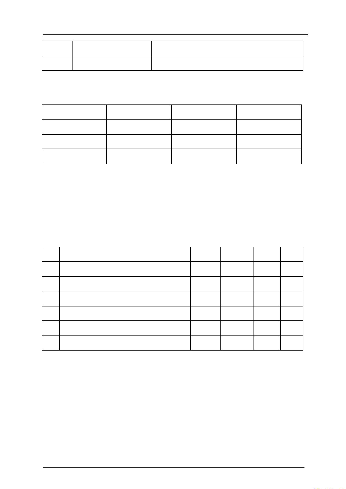
The truth table for the control logic is as follow:
Pin PWM
Pin DIR
Output A
Output B
Low
X (Don’t care)
Low
Low
High
Low
High
Low
High
High
Low
High
7. Power LED Indicator – Power LED. Should be on when the board is powered on.
4. PRODUCT SPECIFICATION AND LIMITATIONS
Absolute Maximum Rating
No.
Parameters
Min
Typical
Max
Unit
1
Power Input Voltage
6-24V2
I
MAX
(Maximum Continuous Motor Current)
--10A3
I
PEAK
– (Peak Motor Current) *
--30A4
V
IOH
(Logic Input – High Level)
3-5.5V5
V
IOL
(Logic Input – Low Level)
000.5V6
Maximum PWM Frequency **
--20
KHz
* Must not exceed 10 seconds.
** Actual output frequency is same as input frequency.
*** Tested in room temperature.
Created by Cytron Technologies Sdn. Bhd. – All Rights Reserved 7
Page 8
ROBOT . HEAD to TOE
Product User’s Manual – HAT-MDD10
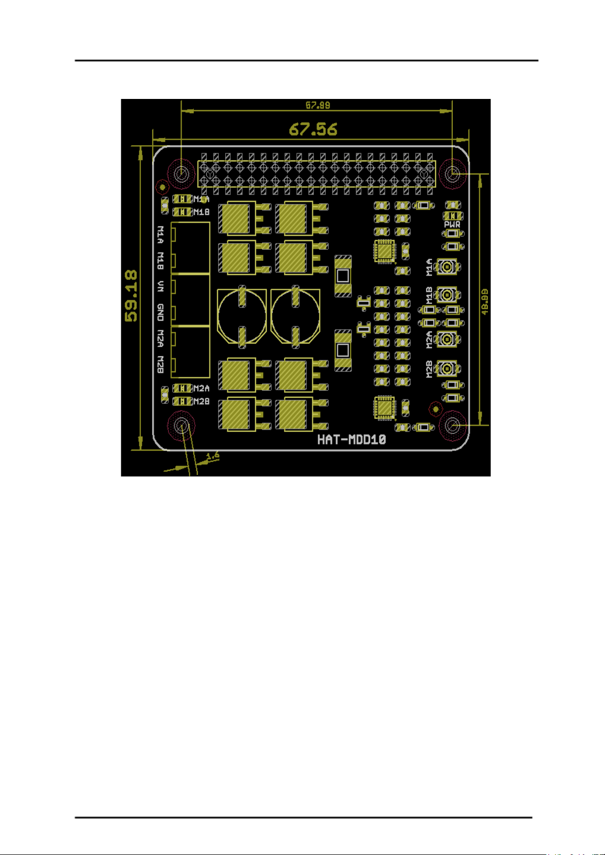
5. DIMENSION
Footprint Dimension
Created by Cytron Technologies Sdn. Bhd. – All Rights Reserved 8
Page 9
ROBOT . HEAD to TOE
Product User’s Manual – HAT-MDD10
6. GETTING STARTED
Hat-MDD10 is compatible with 2 types of PWM operation, which are:
1. Sign-Magnitude PWM – For sign-magnitude PWM operation, 2 different control signals are
used to control the speed and direction of the motor. PWM is feed to the PWM pin to control
the speed while DIR pin is used to control the direction of the motor.
2. Locked-Antiphase PWM – For locked-antiphase PWM operation, only 1 control signal is
needed to control the speed and direction of the motor, while another input is to enable the
driver. PWM pin is connected to logic high while the DIR pin is being feed with the PWM
signal. When the PWM signal has 50% duty cycle, the motor stops running. If the PWM has
less than 50% duty cycle, the motor will turn CW (or CCW depending on the connection). If
the PWM signal has more than 50% duty cycle, motor will turn CCW (or CW depending on
the connection).
Sample connection diagram is as follow:
Created by Cytron Technologies Sdn. Bhd. – All Rights Reserved 9
Page 10

ROBOT . HEAD to TOE
Product User’s Manual – HAT-MDD10
6. WARRANTY
● Product warranty is valid for 12 months.
● Warranty only applies to manufacturing defect.
● Damaged caused by misuse is not covered under warranty
● Warranty does not cover freight cost for both ways.
Prepared by:
Cytron Technologies Sdn. Bhd.
No. 1, Lorong Industri Impian 1,
Taman Industri Impian,
14000 Bukit Mertajam,
Pulau Pinang, Malaysia.
Tel: +604-548 0668
Fax: +604-548 0669
URL: www.cytron.io
Email: [email protected]
Created by Cytron Technologies Sdn. Bhd. – All Rights Reserved 10
 Loading...