

Cytech Comfort I, Ultra Comfort II, ULTRA Comfort II Optimum Installation Manual

Comfort II
Installation
Manual
Comfort, the Intelligent Home System

This page intentionally left blank.

41
Using 12V Supplementary Supplies
.......................
40
12V Auxiliary Supply Outputs (12V and S12V)
.............
40
Using Lamps for Output Testing
............................
37
Output Terminals OP1 - OP8 (JP11-JP14)
..................
36
Negative Applied Detectors
.................................
35
Tamper Input (JP1)
.........................................
31
Zone Input Terminals Z1-Z8 (JP3 - JP6)
...................
29
Telephone Connections
.....................................
27
Siren (JP9)
..................................................
26
Speaker and Strobe (JP10)
.................................
23
Keypad and Door Stations
..................................
22
Cable Routing / Requirements
.............................
22
Factory Restart
.............................................
20
Backup Battery (JP2)
.......................................
20
Transforme
r
................................................
19
Location and Mounting of Panel
............................
18
Shunts/Settings - Analog Section
..........................
17
Shunts/Settings - Digital Section
...........................
17
Connections - Analog Section
..............................
16
Connections - Digital Section
...............................
16
Connections - Analog Section
..............................
16
Key Integrated Circuits (ICs)
..............................
16
Installation Diagram
........................................
16
Section 2 Installation
..................................
12
Design Considerations and Applications
....................
11
Comfort Architecture
.......................................
9
Comfort II Features
..........................................
6
Comfort Documentation
.....................................
5
Ordering Information - Products and Accessories
...........
2
Specifications
................................................
2
Section 1 General Information
.....................
Comfort II Installation Manual

52
Doorbell Chime is too loud
...................................
52
Playback of Recording from the Keypad is Distorted
...............
52
None of the Indicator LEDs on the Keypad are on
.................
51
Cannot Sign in on Keypad
....................................
51
Pressing any key gives a long beep
.............................
51
Keypad keys do not beep when pressed
.........................
51
Keypad Beeps continuously
...................................
51
Keypad/ Door Station Problems
............................
50
Communications Failure
....................................
50
System does not work, and Heatsink is very hot
..................
49
The Red and Green LEDS both come on after 5 seconds:
..........
49
The Green LED remains on after 5 seconds, i.e. does not blink
......
49
The Red and Green Leds do not come on after Power Up
...........
49
Start-up Problems
..........................................
49
Troubleshooting Kit
.........................................
49
Section 4 Troubleshooting
...........................
48
Remember to set Time and Date
...........................
48
Door Station
................................................
48
Voice Station
................................................
47
Remote Phone Access
......................................
47
Local Phone Access
.........................................
47
Answering Machine
.........................................
47
Home Control Menu
........................................
46
Dialout/ Telephone Numbers
...............................
46
Security/ Zones
.............................................
46
Section 3 Testing and Commissioning
..........
45
Quick Start Power-On Checklist
............................
44
RGR04 Ringe
r
...............................................
43
Local Expansion Modules
...................................
42
X10 Connection (MJ1)
......................................
41
Resettable Fuses
...........................................
Comfort II Installation Manual

61
End of Line Resistors
.........................................
60
False Alarm on Disarming
.....................................
59
Use Event Log
..............................................
58
Tracing Alarms
..............................................
58
Engineer Code Lost
..........................................
58
User Code Lost
..............................................
58
Sign-in Codes Lost
..........................................
58
No Voice on Keypad when Arming or Disarming
..................
57
“Call Engineer to Reset” announcement when trying to Arm
........
57
Keypad Disarm has delay before “Security Off”
...................
57
Arm Fail after the Entry Door is closed
..........................
57
Arming/Disarming Problems
................................
56
System Cannot Dial Out
.....................................
56
System Does Not Answer Incoming Call
.........................
56
Special Telecom Services (e.g.. Call Forwarding and Voice Mail)
....
56
The Users Line is always Busy
.................................
55
Customer’s Caller ID Does not work
............................
55
Customer has their own Answering Machine
.....................
55
Telephone Relays click every 10 seconds without getting “Phone
Trouble”
...................................................
55
Parallel Phones at TEL IN
.....................................
54
"Phone Trouble"
.............................................
54
Cannot Sign in on Local Phone
.................................
54
No Dial Tone on Local Phones, incoming call does not ring phones
...
53
House Telephones do not Ring
.................................
53
Phone Problems
.............................................
53
Keypads go into Intercom Mode by themselves
...................
53
Door Station cannot Ring the Telephone
........................
53
Telephone hears only Noise from Keypad/Door Station
............
52
Door Station or Keypad cannot hear voice from telephone
.........
52
Telephone cannot hear Voice Station or Door Station
.............
Comfort II Installation Manual

63
How to recover lost User Codes
................................
63
How to disable Telephone Line Cut detection
.....................
62
How does Comfort handle Telephone line Cut?
...................
62
Can a PIR be used as an Entry Door zone for Final Door Arming?
....
62
Does the system rearm after an alarm?
.........................
62
Is the Siren Duration restarted during Alarm by new zone
activations?
................................................
62
Frequently Asked Questions
................................
61
Zone Trouble
...............................................
Comfort II Installation Manual

Comfort II Installation Manual
1

SECTION 1 GENERAL INFORMATION
Specifications
Zones
w 8 fully programmable zones on Control Panel, expandable to 16 with
Local Expansion Module (LEM) and 64 with Slave Expansion Modules
(SEMs)
w Each zone configurable for 0 or 2 end-of-line resistors
w Up to 32 predefined Zone types to simplify zone configuration
w Surge/Over voltage protection for each zone
Power Supply
w US: 16.5 V 40VA Class II UL Listed transformer should be used.
w Minimum Standby Battery requirement: 12V, 7 AH sealed lead-acid
battery. (UL985: One 7 AH battery for 24 hour standby with 200 mA
auxiliary current, or two 7AH batteries for 24 hour standby with 400 mA
auxiliary current). Reverse protection for battery.
w 1.5 A regulated DC supply with Resettable Fuse protection
w Supervised for Mains failure and low battery
w Built-in protection against deep discharge of battery shuts down system
when battery falls below a threshold, preventing damage to the battery.
w Current-limited (400 mA) battery charging allows system to work while
charging a very weak battery
Auxiliary Supply Outputs
w 12V unswitched supply
w 12V switched supply (programmable reset for latched detectors)
w Note: Both switched and unswitched auxiliary supplies and 8 Outputs
have a combined continuous current limit of 1A. (500 mA for UL
applications)
Alarm Outputs
w Speaker Drive with 20 siren patterns
w Siren Output with programmable siren pulse patterns.
w Strobe output (12v)
w Combined Alarm Output current of 1.5 A max (with battery)
System Supervision
w Low Battery
w Mains failure
w Telephone Line cut
w Individual Zone tamper (open-circuit or short-wiring) with 2 end of line
resistors
w Dedicated 24 hour Tamper input (used for cabinet and siren tamper)
Memory
Comfort II Installation Manual
2

w Nonvolatile memory maintains configuration during total removal of
power
w Event log with 250 events (FS18) or 125 events (FS17) which can be
accessed remotely or locally.
Alarm Types
w 32 programmable alarm types including user-definable alarm types
w Predefined alarm types include Intruder, Fire, Panic, Duress, Arm ,
Disarm etc.. Each alarm type selects a siren pattern, telephone
combination, can trigger a user-defined response, which turns on/off
appliances, lights etc.. Each alarm type can be set to report to any
combination of the telephone numbers
Dialer / Digital Communicator
w 8 programmable telephone numbers. Each alarm type activation can be
programmed to dial to any combination of telephone numbers.
w Each number can be assigned to Central station, voice phone, personal
pager, or recorded voice message.
w Pager automatically displays system ID, alarm type and Zone or User
number (depending on the alarm type)
w 2 Central Monitoring station numbers with individual account numbers.
w Digital communicator formats supported include all major pulse formats
(3x1, 4x1, 3x2, 4x2 at 10 pps, 20 pps and 40 pps), and Contact ID.
Outputs
w 8 open collector outputs on main board, expandable to 16 with Local
Expansion Module, and 64 with Slave Expansion Modules
w Each output can drive external relay or infrared LED for remote control
appliances. RLY02 Relay Modules with 8 or 4 relays are available.
w Selectable Pulsed or Latched output activation.
w Infrared codes (air conditioners, home entertainment) can be sent to
any output.
w Maximum combined output current of 300 mA for all 8 outputs, 150 mA
max for any one output.
w Over voltage and Surge-protected outputs.
X10 Compatibility
w Built-in two-way interface to X10 network via PSC05 (110V 60 Hz)
TW7223 or XM10E (230V 50 Hz) module. X10 modules not supplied
Keypad / Door Station
w Up to 8 Keypads and 3 Door Stations per system (Require auxiliary
Power Supply for more than 4 Keypad/Door station combinations
w Keypad/Door Station current consumption : 15 mA (idle), 120 mA with
siren
w KP04 with LCD, KP03 without LCD
w Indicator LEDs: Home/Trouble, Armed/Alarm, Power Failure/Low
Battery, New Message, Microphone on.
w Voice and siren sounds
Comfort II Installation Manual
3

w Built-in microphone for recording, intercom and alarm verification
w Full-duplex intercom between telephone and Keypads and Door
Stations, and Keypad to Door Station.
w Tamper switch
w Communications Failure Trouble alarm
w Backlighted keys
Telephone Answering machine
w Digital Answering machine with 10 minutes of recorded messages
w 8 programmable mailboxes with individual sign-in codes, or common
mailbox.
w Recorded messages with individual time/date stamps.
w Answering machine is accessible from any phone in the house.
w Call screening option on Keypad
w Recordable greeting message and user names for each mailbox.
w Messages are automatically played back when the mailbox user signs in,
or may be accessed from any telephone. New messages can be
forwarded to a phone or pager for each mailbox.
w Automatically erases the oldest saved message when a new message is
recorded and recording memory is full.
False Alarm Filtering Features
w 2 way voice on Keypad
w Voice Alarm History with Date and Time of zone activation.
w Voice Alarm Tracking in real time of activated zones
w Alert zone types require activation of another zone to trigger a
confirmed alarm
w Local alarm warning option for delay entry time-out prior to full alarm.
w Open- or short-circuit zone condition can be signaled as a trouble
condition (when 2 end-of-line resistors are used)
w Night Mode Delay zone setting.
w Double sign-in of duress code required to generate duress alarm.
Sign-in Codes
w 16 user codes with individual authorization for arm and disarm, local and
remote access, and disarm after alarm. First 8 user codes for mailboxes
w Engineer code for system and security settings.
w Sign-in Tamper alarm for protection against repeated sign-in code
attempts.
Emergency Buttons
w Quick activation of Fire and Panic on keypad.
Test Features
w Battery Test - Immediate or at programmed intervals
w Security Check (walk test) zone activation is announced on Keypad
w Dial test - dials to all programmed telephone numbers, pagers, Central
Stations, audible on Keypad
Comfort II Installation Manual
4

w Siren Test - Momentary activation
w Strobe Test. - turns on and off the strobe.
w Engineer Test Mode - allows engineer to work on the system without
triggering tamper or 24 hour alarms.
Event Log
w 250 Events
w Full voice log, with date/time stamp and voice description of events
w Local or remote access.
w Select 1st event, last event, previous event , next event , next day,
previous day for quick navigation.
w Uploadable to PC using COMFIGURATOR for Windows, may be printed or
saved
Other Features
w Door Station intercom with home or remote phones (requires Door
Station and RGR03 Ringer)
w Voice Reminder Messages capable of dialout to pager and telephone.
w Time Programs
w User-programmable Timers
w Vacation programs
w Remote Programming from any phone with Engineer Sign in code.
Ordering Information - Products and Accessories
w CP9000-EXP : Comfort II with Enclosure, Transformer and User Manual
w LEM01-M2 - Local Expansion Module (8 inputs, 8 Outputs)
w LEM02-M2 - Local Expansion Module (8 inputs, 0 outputs)
w KP03 - Voice Keypad with IR receiver
w KP04 - LCD Keypad with IR receiver
w KT01 - Touchscreen keypad 10 cm
w DP03 - Door Station
w SEM01 - Slave Expansion Module with built-in battery charger
w SEM02 - Slave Expansion Module (requires 12V external supply)
w UCM/IR - Universal Communications Module with IR Learner and RS232
interface for Comfigurator upload/download
w UCM/Ethernet - Universal Communications Module with Ethernet
interface for Comfigurator upload/download
w UCM/CBUS - C-Bus Interface Module
w UCM/EIB - EIB Interface Module
w UCM/GSM - GSM Interface
w UCM/Smartfit - Honeywell Smartfit Interface Module
w UCX01 - RS232 Interface for interface for PC, touchscreens,and
third-party systems. Not for IR Learning or Comfigurator download.
Comfort II Installation Manual
5

w CWM01 - Comfort Webserver Module for connection to Local Area
Network or Internet
w LP01 12 V lamps for testing
w RLY02/4 4 way Relay Module
w RLY02/8 8 way Reed Relay Module
w CSM03/PCB - Dual Current Sensor PCB supports 2 CSM03-CT sensors
w CSM03-CT - Current Transformer, 2 CSM03-CT are connected to 1
CSM03-PCB
w RC01/YE Handheld Remote Control (Yellow) with 50 keys
w RC01/PU Handheld Remote Control (Purple) with 50 keys
w SCS01 - Scene Control Switch with 4 buttons and indicators. Up to 8
SCS/RIO combination in a Comfort Pro or Ultra system
w RIO01 - Remote Input/Output Module with 8 Digital inputs and 8
open-collector Outputs. Up to 8 SCS/RIO combination in a Comfort Pro
or Ultra system
w IRR01 - Infrared Receiver for RIO.
w TWS01 Single Lighting Control Module (for two way switching)
w TWS02 Dual Lighting Control Module (for two way switching)
w IR01W Infrared transmitter cable assembly for short range (round led)
w IR02W Infrared transmitter cable assembly for short range (flat led)
w IRD01 Infrared Dome with Infrared transmitters and Infrared Receiver.
Requires RIO01.
w RGR04 Ringer Module required for Door Station
w ZTS01 Zone Test Switch
w VPG02 Voice Programmer Module
w T-UL - UL-listed Transformer (16.5V, 40VA) manufactured by Macon,
Type ATW-1640
w BT1270 - Battery 12V 7AH
w EOL4.7K - 4.7K End-Of-Line insulated resistors
w EOL2.7K - 2.7K End-Of-Line insulated Resistors
w TB02 - 2 way Terminal Blocks
w TB03 - 3 way Terminal Blocks
w WA485 - 4 way cable for Rs485 connection to UCM modules
Comfort Documentation
Technical Manuals
The Comfort Technical Manuals are meant for installers. They are divided
into several booklets for better organization and to make it easier to find
the desired information.
Comfort Installation Manual
This manual includes the specifications, installation, setup, wiring
requirements, testing/commisioning, troubleshooting, and FAQs.
Comfort II Installation Manual
6

Programming with Comfigurator
Shows how to use the Comfigurator software tool to program Comfort.
Discusses the programming concepts, techniques and programming
strategy.
Comfigurator Reference Manual
This describes the Comfigurator software and shows how to use each
screen and feature. It is essentially the HELP file for Comfigurator.
Programming by Engineer Menu
This shows how to program Comfort using the Engineer Menu by keypad
or telephone.
Programming Worksheet
If you are programming Comfort using the Engineer Menu, the
worksheet is the place where you write down your customer
configuration and programming settings. We strongly recommend that
you do not attempt to install a system without using this worksheet as it
will make your programming much easier, and prevent you from missing
any settings. A detailed record of how each system is configured is
crucial for proper management. Also, keep it updated as any future
changes are made.
Action Codes Reference
A Complete list of Actions and how they are used. Action codes are
commands for Comfort. These are assembled into Responses (sometimes
called “Macros”) to produce multiple operations. Master these and you
can make your Comfort system do what no other system can. Action
Codes can be specified in Comfigurator’s Response Wizard
You can get the system up and running with the default settings, but it is
likely you will want to do some of the clever things which attracted you
to Comfort in the first place. You will need a good grasp of Action Codes
and how they are used in Responses.
Applications Manual
The applications manual shows how to use Action codes and Responses
to program Comfort in commonly used scenarios. This is updated as
new applications and solutions are added.
Training Materials
Check with your Comfort distributor or Cytech Technology for new
Training Materials, like presentations, tutorials, exercises etc. which are
updated from time to time.
Modules
Each of the modules and accessories listed in the previous section comes
with its own manual.
Comfort II Installation Manual
7

For Users
User Manual with Quick Start Guide
The Quick Start Guide gives simple instructions on how to get started
with Comfort. The rest of the User Manual is a detailed users guide for
those who want to make full use of Comfort’s unique capabilities.
Quick Reference Card
This folded card is handy reference to Comfort which can be kept in a
purse or wallet.
Internet
Cytech Technology Web site
Our Web site at http://www.cytech.biz has all the manuals and other
documentation, FAQs, applications, brochures, as well as software which
can be downloaded. Other sections include News, Features, Products,
Distributors, and an interactive demonstration.
Comfort User Groups
Join our user forum on the Internet on Yahoo Groups at
Http://groups.yahoo.com/group/comfort-technical/
Click on Join. This user group is a forum for discussion, comments,
problems, new product announcements and technical support for
Comfort Users.
Comfort II Installation Manual
8

Comfort II Features
The table below shows the features compared to Comfort I Ultra
YesYesYesVoice Download
YesYesYesRS232 Commands
166416User Timers
646464Flags
128256256Counters
NoYesYesRC01 Rooms/Scenes
0128128IR Receive Codes
YesYesNoBranch Instructions
YesYesNoFull Duplex Intercom
Phone/KP/DP
688Codes per Response
1281,0231,023Responses
250250250Event Log (events)
540 bytes
(typ 16 codes)
4096 bytes
typ 120 codes)
4096 bytes
(typ 120 codes)
IR Code Memory (Send)
8
88Vacation Programs
31
3131Zone Types
31
3131Alarm Types
Yes
YesYesLocal Phone Control
Yes
YesYesRemote Phone Access
16
1616User Sign-in Codes
163216Time Programs
8168Reminder Messages
YesYesYesExtended X10 codes (Send)
11616Receive X10 (Housecodes)
16
1616X10 House Codes (Send)
10 minutes
10 minutes10 minutesRecord Time
8 Mailboxes
8 Mailboxes 8 Mailboxes Voicemail
UCM/GSM
UCM/GSMUCM/GSMSMS
8 phone numbers, incl 2 CMSDialout for Alarm
100
600600Commands on Home Control
Menu
10
1010Control Actions per device
10
1010Control Devices per Group
1
66Control Menu Groups
16
128128Max Outputs
0
6464Max Non-alarm Inputs (RIO)
64
6464Max Alarm Inputs
FS31 (64k)FS24 (256 k)FS24 (256K)File System Memory (U4)
“Help”“Week”“Action”Firmware announcement (U1)
Comfort II OptimumComfort II ULTRAComfort I Ultra
Model
Comfort II Installation Manual
9

0158RIO/SCS
333SEM
333DP
888LCD
Comfort II OptimumComfort II ULTRAComfort I Ultra
Model
Comfort II Installation Manual
10
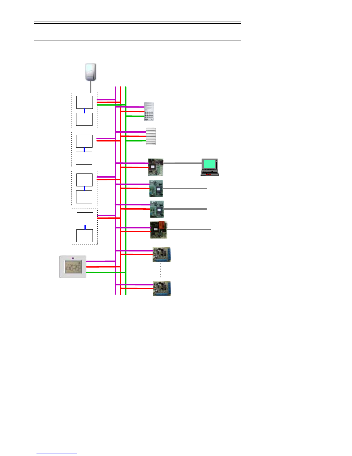
Comfort Architecture
SEM
LE M
Main
LE M
SEM
LE M
SEM
LE M
12V/GND
KA/KB
MIC/VOICE
KP 1 to 8
DP 1 to 3
SEM 1
I/P 17 to 24
O/P 17 to 24
SEM 2
I/P 33 to 40
O/P 33 to 40
SEM 3
I/P 49 to 56
O/P 49 to 56
Input 1 to 8
Output 1 to 8
I/P 9 to 16
O/P 9 to 16
I/P 25 to 32
O/P 25 to 32
I/P 41 to 48
O/P 41 to 48
I/P 57 to 64
O/P 57 to 64
UCM01
RS232
UCM/CBUS
UCM/EIB
CBU S
EIB
X10
Touchscreen
RIO #1
Digital/IR Input 129 to 136
Output 129 to 136
UCM/Ethernet
Ethernet
RIO #8
Digital/IR Input 185 to 192
Output 185 to 192
The above diagram shows how Comfort can be expanded in relation to
its architecture.
The Main Comfort panel contains 8 inputs and 8 open-collector Outputs
with dedicated Tamper Input and Siren, Strobe and Speaker outputs. A
Comfort II Installation Manual
11

Local Expansion Module provides another 8 inputs and 8 outputs (LEM01)
or 8 inputs (LEM02) in the same enclosure, to give a maximum of 16
Inputs and 16 Outputs. The Outputs are open-collector transistors,
capable of driving 12V relays or infrared transmitter LEDs.
The Slave Expansion Module (SEM01 with its own battery charging
circuit, or SEM02 which requires an external power supply) provides
another 8 Inputs and 8 Outputs with dedicated Tamper Input and Siren,
Strobe and Speaker outputs. A Local Expansion Module can be connected
to the SEM to provide another 8 inputs and 8 outputs (LEM01) or 8
inputs (LEM02) in the same enclosure, to give a maximum of 16 Inputs
and 16 Outputs with the Slave.
Up to 3 Slaves (SEM) with their own Local Expansion Module can be
connected to the Main Comfort panel for a maximum of 64 Inputs and 64
(open-collector) Outputs.
Remote Input/Output Modules (RIO) each provide 8 digital or Infrared
Inputs. These RIO digital Inputs cannot be used as alarm inputs like
those of the Main and Slave Expansion Modules. Infrared Receivers
(IRR01) can be connected to any RIO input to allow Remote Controls like
Comfort RC01 and Philips Pronto to send commands to Comfort (received
Infrared Responses). Normally Open switches can also be connected to
each RIO input to activate Responses. Up to 8 RIOs can be connected to
Comfort to provide 64 Digital/IR inputs and a further 128 open-collector
outputs.
With 3 SEMs, 4 LEMs and 8 RIOs Comfort has a maximum capacity of 64
Alarm/Digital Inputs, 64 Digital/IR Inputs, and 128 open-collector
Outputs.
The Universal Communications Module UCM01 provides an RS232
Interface to PCs and serial devices. It is used for upload/download
programming using the Comfigurator software tool, and for interfacing to
third-party software like WizComfort and other systems with serial
interfaces like AMX, Crestron, and Homevision.
Other types of UCM include UCM/EIB for interface to the European
Installation Bus, or Instabus; UCM/CBUS for interface to Clipsal’s C-BUS;
UCM/Ethernet to an Ethernet Local Area network. Up to 8 UCMs can be
connected to a Comfort system.
Design Considerations and Applications
Run Additional Cables
If you require a 6-core cable to a part of a building, run an extra 6 core
cable as well, you never know what may be needed in the future! If
possible, (although not a requirement) use screened cables for
trouble-free installations. The same applies to CAT 5 cables.
Current Consumption
It is very easy to underestimate the load which can be placed on a
system unintentionally. Before starting to run cables, find-out the
Comfort II Installation Manual
12

current draw from all the devices to be attached to the system FIRST. I
t
may be that supplementary power supplies will be needed sooner than
you think. If the standby current is over 850 mA install a Power Supply
Unit (PSU).
Plan for the Future
Comfort is one of the most expandable systems around! Installers can
benefit from ongoing upgrades and modifications as there is so much
‘add-on potential’. Selling to an existing customer is always easier than
finding new customers. A customer may wish to connect to a Central
Station or add security lighting. They may require home control using
X-10 or operate the curtains, or they may just want more detection
points, a camera or Keypad, additional intercoms or even flood
detection!. A little forethought during the initial installation can make
upgrading a system in the future so much easier. Future proof every
installation for Comfort!
Always allow for extra capacity in the cables. If more zones or outputs
are required, run extra cables to the other end of the building so you can
install Keypads. Customers may have already shown an interest in these
things and plan to add them at a later date. If you are already taking
cables in a certain direction, increase the capacity. You may need to
estimate what a customer might need in the future. Some companies
prefer to install Comfort as a 'basic system' and take a planned approach
to their marketing by sending special offers throughout the year to
stimulate the interest in time for their annual inspection and do the
update at the same time.
End of Line Resistors
Use 2 End of Line resistors for added security. You only need a pair of
conductors per zone to give both zone information and tamper
protection. The resistors should be fitted into the detector.
X-10 in New House Builds
The ideal time to integrate Home Control functionality is during the
planning and design stages of new homes so that the cabling between
wall switches and lamp fittings can be configured to use AD10 or LD10
DIN rail modules sited in a separate container near to the Comfort Panel
and possibly the fuse board. Bring the wall-switch cables AND light
fitting cables back to the X10 consumer unit, rather than the usual
convention of running wall-switch cables to the light fitting and the light
fitting to the mains supply. This gives maximum flexibility as you can
still use the wall switch or Comfort to control the light. This is because
the wall switch is actually switching the AD10 module which in turn
switches the mains onto the bulb. Distance and noisy mains supplies can
seriously impact the strength of X-10 signals around a house. Test the
house first, using the UR24 and Radio Transceiver Module. These two
devices can also be used to provide a wireless interface to perform any
of Comfort's Responses. See 'X-10 received codes' in Worksheet Table
32.
Comfort II Installation Manual
13

X-10 house codes can be categorized by their applications. You may
need to switch OFF all of one particular address at once. You could use
X-10 'A' address' as general switching, 'L' for external lights, 'H' for
Heater (i.e. Central Heating) etc.. Never use X-10 to control appliances
which could create a dangerous situation if suddenly switched ON or left
ON for long periods of time
Lighting Control Linked to Security
When someone enters the property through the front door when the
system is armed, the hall or front lights can be switched on if the light
level, (determined by a photocell) is low.
If an Intruder Alarm occurs, the lighting in the violated are may be
turned on so the owner can quickly identify the areas of possible
intrusion.
If a fire is detected, lights in the exit route can be turned on.
Monitoring Outside Movement
Outside PIRs can trigger announcements of programmed descriptions
e.g.. “Front Garden”, “Garage”, “Driveway” on the Keypads.
External movement can be programmed to trigger user-recorded
warning messages like “Please leave the area at once or else...” In
stores, movement in certain aisles may also trigger more friendly
messages.
Several CCTV cameras may be positioned outdoors, connected to a
common monitor, switched by relays depending on which outside PIR
detects movement. Relay Modules with 4 relays are available. When the
Doorbell is pressed, the front door camera could be switched through.
For lighting, the same external PIRs could be used to operate lighting.
The prevailing light level can be determined by using a photocell
connected to a zone, and the corresponding light turned on if it is dark.
One of the 8 timers could be used to switch off the lights a few minutes
later if no further movement is detected. You may also wish to start a
time lapse video machine using a different output (set the record time to
3 minutes at a time).
Wireless Zones
Some installations may require radio control of certain zones such as
panic switches, arming, or maybe even zone shunting. These can be
achieved using stand-alone radio (RF) transmitters and receivers. The
resistors for each zone would normally be fitted across the relays inside
the receiver’s box.
RF transmitters often have 2 to 4 switches and allows customers to have
their Garage Door or Gate to also be controlled from the one transmitter.
This is relatively simple to achieve because Garage Doors are often
manually opened using a normally open bell-type push-switch. To
provide control using a spare channel of the transmitter, simply connect
Comfort II Installation Manual
14

the receivers normally open relay across the bell-push terminals in
parallel.
Automatic Gate Control
Comfort can be connected to control automatic gates using the outputs
and the 12 Volt RLY01 relay board. Often these are triggered by a
pulsing a normally open contact for 1 second using action code 130. The
gate may close after a preset time or when another Pulse command is
given. The Open Gate or door command can be given from the Door
Station menu when used in conjunction with the Door Station
Curtain Control
Comfort can be used to operate some curtain controllers. This can be
achieved using two outputs per curtain controller, one to open and one
to close'. Usually the output is pulsed for about 1 second to trigger the
curtain controller. It is advisable to consider the position of movement
detectors when operating a curtain while the system is armed as this is
capable of causing a false alarm' To avoid this, install the detector in the
corner adjacent to the curtains so that the curtain movement is not in
the detector's field of view or write the curtain ON and Off Responses to
include the shunting of the zone using the bypass action code(75) then
pulse the output to open the curtain then run a 20 second timer and
unbypass the zone (76).
Comfort II Installation Manual
15

SECTION 2 INSTALLATION
Installation Diagram
Refer to the full page Installation diagram supplied with Comfort which
shows all the connections, shunts, and the main Integrated Circuits and
components on the Comfort printed circuit board assembly. This is not
shown here due to lack of space.
The Comfort controller printed circuit board is made up of two sections;
the Digital Section and Analog Section joined by a 28 way connector in
the centre. The Digital section consists of the microcontroller, memory,
Inputs, outputs and logic circuitry while the Analog section consists of
the telephone interface, power supply, Voice and dialing functions.
Key Integrated Circuits (ICs)
U1 - Microcontroller. This IC contains the firmware for all of Comfort’s
embedded behaviour.
U4 - System configuration Nonvolatile Memory (NVM). This is where all
downloaded Programming information for a system setup is stored.
U5 - RS485 Interface IC.
U51 - Digital Signal Processor (DSP) IC. For Comforts voice menu and
messages. It may be reprogrammed for other vocabularies by
downloading a vocabulary using the Comfigurator software tool.
Connections - Analog Section
AC (JP51) - Connected to Transformer secondary 14VAC
BATT (JP52) - 12V Battery Connection for 7AH Sealed Lead-Acid
Rechargeable Battery.
TEL IN (MJ51) - Connection to Public Switched Telephone Network.
TEL OUT (MJ52) - Connection to House phones.
KP MIC/VOICE (JP53) - connection to Keypads
DP MIC/VOICE (JP54) - connection to Door Stations
Connections - Digital Section
X10 (MJ1) - RJ11 socket for connection to X10 PSC05/TW523/TW7223
Interface. DO NOT connect a telephone line to this socket
TAMP/COM (JP1 ) - Connection to Tamper of Panel and Siren/Bell box.
Short the terminal block with wire if tamper Input is not used.
Z1/COM/Z2 (JP3) - Zones 1, 2 Centre ground (3 position terminal block)
Z3/COM/Z4 (JP4 ) - Zones 3, 4 Centre ground (3 position terminal block)
Z5/COM/Z6 (JP5) - Zones 5, 6 Centre ground (3 position terminal block)
Z7/COM/Z8 (JP6) - Zones 7, 8 Centre ground (3 position terminal block)
Comfort II Installation Manual
16

S12V/COM/12V (JP7) - 12V Auxiliary and Switched Supply (3 position
terminal block)
KA/KB (JP8) - RS485 connection to keypads, UCMs and other modules (2
position terminal block)
SRN+/SRN- (JP9) - Siren/Bell Connection (12V), SRN- terminal is the
negative trigger, SRN+ is fixed 12V.
STR/12VF/SPK (JP10) - Speaker and Strobe Connection for Speaker
and 12V Strobe Light. Centre pin is at fixed 12V. STR and SPK go to 0V
when triggered (negative trigger)
OP1/12V/OP2 (JP11) - Output 1 and 2, centre 12V common (3 position
terminal block)
OP3/12V/OP4 (JP12) - Output 3 and 4, centre 12V common (3 position
terminal block)
OP5/12V/OP6 JP13) - Output 3 and 6, centre 12V common (3 position
terminal block)
OP7/12V/OP8 (JP14) - Output 1 and 2, centre 12V common (3 position
terminal block)
LEM (J5) - LEM Connector for ribbon cable.
OP (J12, J13) for the OP01 Output driver plug-in module. This can be
replaced if the outputs are danaged.
RS485 (J6) - 4 way connector for RS485 modules eg UCM, SEM for short
distance only using 4 way cable (WA485)
J1 - 28 way connector for Analog section
J8 to J11 - 2 x 10 female header for mounting of MPU01 upgrade
firmware module
Connections - Analog Section
AC14V (JP51) - Connection for transformer secondary (NOT for Mains
voltage)
TEL IN (MJ51) - to incoming Telephone Line
TEL OUT (MJ52) - to telephones in the home/office
BATT (JP52) - To sealed lead-acid backup battery
KP (MIC/VOICE) to Keypads Mic/Voice
DP (MIC/VOICE) to Door Stations Mic/Voice
GSM (J54) - connection to UCM/GSM Module
RGR (J57) - Ringer Board RGR03-M2 mounting
J51 - 28 way connector to Digital section
Shunts/Settings - Digital Section
ID (J3) - DO NOT SHUNT. These are used as ID selection for the SEM
SRNTMP (J4) - Shunt if Siren Tamper is not required. Siren Tamper gives
an alarm if a siren is not connected
Comfort II Installation Manual
17
 Loading...