

Page 1

KT03
Installation
Manual
Comfort, the Intelligent Home System
Page 2

Page 3
SECTION 1 INTRODUCTION
Introduction
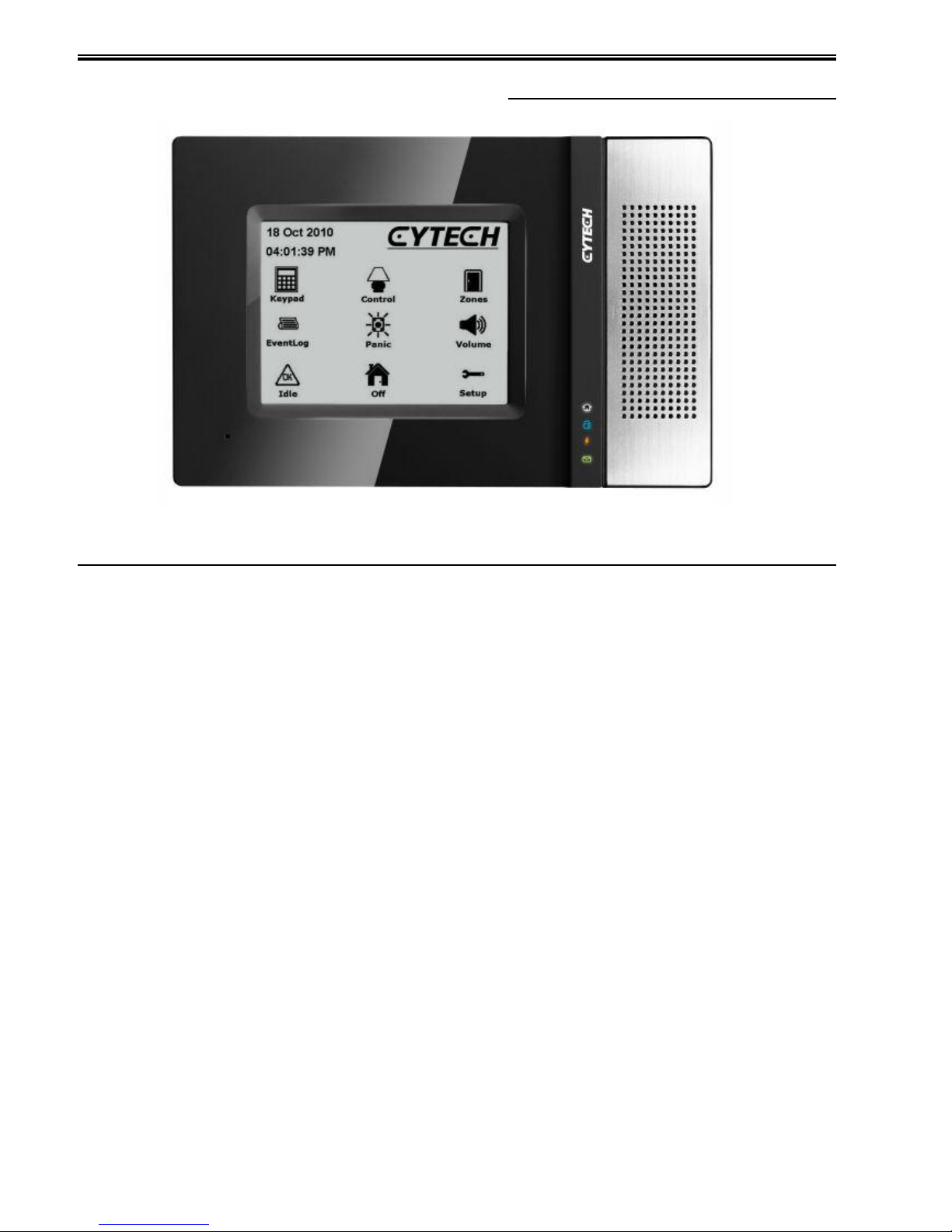
The KT03 has a monochrome 4 inch (10 cm) 320 x 240 resolution LCD with
touchscreen allowing control and visualisation of the Comfort system. The
KT03 can be configured according to the requirements of the user.
Features
Touch-sensitive monochrome LCD display with backlight.
Selectable Orientation - Landscape, Portrait or Landscape Inverted to suit
wall contraints.
Black Translucent, White and Silver faceplates are available.
Speaker for voice announcement, intercom and message playback.
Microphone for message recording and intercom.
Infrared (IR) receiver to receive IR codes from the RC01 handheld remote
control or a universal learning remote control, to control home appliances or
act as a handheld keypad. Note: Translucent Black faceplate is required to
the IR receiver function.
Nonvolatile Flash memory allows hundreds of programmable screens.
Programmable buttons on every page can trigger Responses, simulate
keypad buttons.
Active and Inactive images show status of security zones, Alarms, trouble
conditions, and automation devices.
Status LEDs show the status of alarm and trouble conditions.
64 Schedules to control automation and security independent of Comfort
Time programs
USB port for programming via Comfigurator software.
KT03 Installation Manual
Page 3 of 12
Page 4

Specifications
Overall Dimensions: 170 x 110 x 37.5 mm
LCD Viewing Area: 81.4 x 61 mm
Faceplate dimensions: 176 x 116 mm
Back box dimension: 167 x 111 x 47 mm
Weight: 330g (without back box).
Power supply: 12V 150mA max (when idle) supplied from Comfort
Part Numbers
KT03-BL: KT03 with Black Translucent faceplate. (allows IR receiver)
KT03-AL: KT03 with Silver faceplate (not for IR receiver)
KT03-WI: KT03 with White faceplate. (not for IR receiver)
FR-KT-BL: Spare Black Translucent faceplate with Speaker (no Mic)
FR-KT-AL: Spare Silver faceplate with Speaker (no Mic)
FR-KT-WI: Spare White faceplate with Speaker (no Mic)
Contents
The KT03 consists of the following:
Touch screen assembly in rear housing
Faceplate, removable
Wall Mount box
USB programming cable
4 x partition locking pins for Partition mounting.
4 x mounting screws
6-way green terminal block 3.5 mm pitch.
Extra LED Icon overlays for portrait and Reverse Landscape orientation. The
LED lens for landscape orientation in installed in the KT03 when delivered.
System Requirements
Comfort II ULT/OPT 5.203 and above (preferably 6.XXX)
Comfigurator 3.4.0 and above
UCM 6.008 and above with Ethernet or USB interface for programming
Comfort.
KT03 Installation Manual
Page 4 of 12
Page 5
Connections
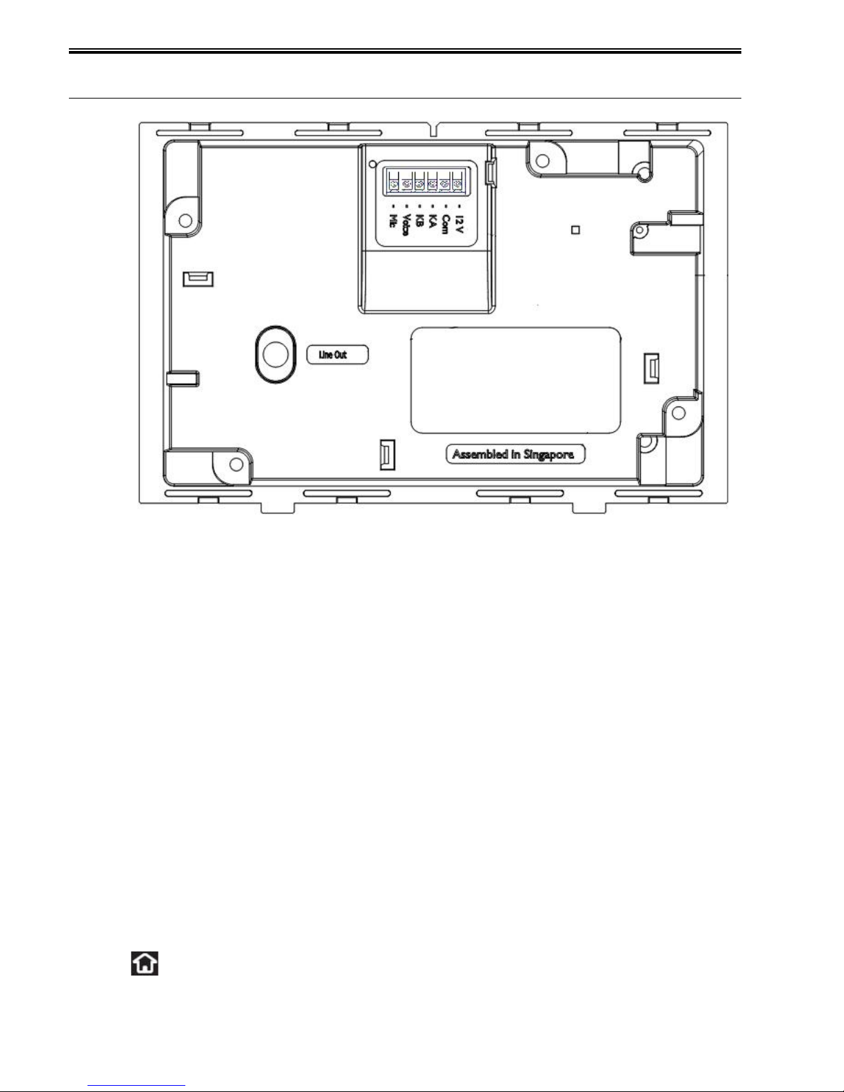
12V - connect to 12V on Comfort (CAT5 Cable)
COM - connect to COM on Comfort. (CAT5 Cable)
KA - connect to KA on Comfort. (CAT5 Cable)
KB - connect to KB on Comfort. (CAT5 Cable)
Voice - connect to KP VOICE on Comfort. (CAT5 Cable)
Mic - connect to KP MIC on Comfort. (CAT5 Cable)
Line Out - connect to external amplifier (optional)
P3 (USB connector), front side after faceplate removed - connect to PC to
transfer KT03 configuration file.
PP3 (PROG), front side after front faceplate removed- 6 pins connector. This
is used for firmware upgrading by UCM programming cable. Note: KT03
Firmware 2.xxx does not use this method of firmware upgrading anymore.
The KT03 should be connected to Comfort by CAT5 cable (preferably
screened to reduce audio noise). The Keypad connections at Comfort can be
shared by all keypads.
Button
SW1 (Reset) front side after front faceplate removed. This button resets the
KT03; it does not change any parameters in Comfort or KT03.
LED Indicators (on front panel)
Off (white) - Steady when Security is OFF (system disarmed), blinking
when there is system trouble (Low Battery, AC Failure, RS485
Communications Failure, Phone Trouble)
KT03 Installation Manual
Page 5 of 12
Page 6

Armed (blue) - Steady when Security is armed, blinking when there is
an active alarm.
AC/Battery (orange) - Steady when AC power is lost, blinking when
Battery is weak
Messages (green) - Steady when there is a new memo (internal)
message, blinking when there is a new external message. Sign in on the
keypad to listen to new messages.
LED Indicators (on PCB)
D12 (Green) - Receive from computer (Comfigurator)
D13 (Red) - Transmit to computer (Comfigurator)
KT03 ID Setting
Comfort is able to support up to 8 keypads, either KP03, KP04, KP05, KP06 or
KT03 in any combination.
The KT03 shares the same ID space as other keypads such as KP03 and
KP04. Do not set any keypad with the same ID as another keypad as this will
cause a conflict and both keypads will not be able to work. When this ID
conflict happens remove the connections from 1 KT03 and set the ID of the
other KT03 which is still connected to a different ID.
In KT03, the ID is set using the KT03 Setup menu. Power up and press the
Setup icon on the home page to go to the Setup Page.
The number keypad will appear. Enter the user code (default 1234#) to
access the setup menu. Go to the ID page and select the ID 1 to 8 of the
unit. If the KT03 is not connected to a Comfort system, the ID can be
changed without entering the user code.
The KT03 ID can also be changed in Comfigurator in KT03 Properties.
KT03 Installation Manual
Page 6 of 12
Page 7

SECTION 2 INSTALLATION
Location
Take note of the following guidelines when selecting a location to mount the
KT03:
KT03 is for indoors use only.
If this is the only Comfort keypad in the premises, the KT03 should be
mounted near the entry door to facilitate arming and disarming of the
security system.
Mount the unit at a suitable height for operating the touchscreen, slightly
below eye level.
The KT03 should not be located where there is excessive humidity, dust or
direct sunlight.
Avoid areas where there may be reflections from windows and light sources
as this may cause unwanted reflections on the LCD.
Mounting Instructions
The KT03 can be mounted in.
1 wooden partition or plasterboard walls using the supplied plastic partition
locking pins.
2 Solid walls of brick and other materials using the supplied wall mount box.
Orientation
The KT03 can be mounted in 3 orientations;
Landscape (normal) with the speaker grille to the right
Portrait (vertical) with the speaker grille at the bottom, or
Landscape (inverted) with the speaker grille to the left.
The Wall mount box has an outline of the touchscreen as a guide to the
correct orientation of the touchscreen assembly to the wall mount box.
The screen images can be designed for any orientation in Comfigurator.
The LED icon overlay on the touchscreen when delivered is for Landscape
(Normal) orientation. If the unit is to be mounted in Portrait or Reverse
Landscape orientation, the LED Icon Overlay on the faceplate must be
changed to the appropriate one (supplied).
To change the Icon Overlay, remove the Front faceplate from the unit, turn it
over and gently peel off the LED Icon Overlay. Remove the adhesive tape
from the new LED Icon Overlay and carefully align it to the correct location
before pressing firmly to fix the lens in place.
KT03 Installation Manual
Page 7 of 12
Page 8

Mounting in Partition Walls
To mount the KT03 in a partition wall:
1 Cut an appropriately sized hole (155 x 99 mm).
2 Insert the supplied screws to the partition locking pins and tighten it just
enough to hold the partition locking pins in place.
3 Place the KT03 on the wall.
4 Tighten the four screws through the four partition locking pins. The pins will
rotate and ultimately clamp the touchscreen assembly to the wall.
Mounting in Solid Walls
To mount the KT03 using the Wall Mount box:
1 Create a hole in the wall of the appropriate size according to the Wall Mount
Box.
2 Pull the cable through the Wall Mount box and place the Wall Mount box into
the wall.
The Wall Mount box must be mounted with the correct orientation
with the Touchscreen assembly. There is an outline of the KT03
engraved on the Wall Mount box which shows the correct orientation
for second fix.
3 Insert the supplied screws into the four holes and tighten them to fix the
Touchscreen assembly to the Wall Mount box.
Attaching the Front faceplate
1 Position the front faceplate over the touch screen with the speaker window
on the right. Hook the top of the front faceplate over the top of the KT03.
2 Press the bottom of the front faceplate with the catches over the bottom of
the KT03 until you hear it snap into place.
Removing the Front faceplate
The front faceplate must be removed in order to reprogram the KT03 via the
USB port.
1 Hold the front faceplate and apply pressure downwards to the bottom of the
KT03.
2 Pull the faceplate away from the bottom side keeping the top side catch in
place. Be gentle with this in order as not to pull away the Speaker wire from
the Speaker mounted on the faceplate.
Firmware Upgrading
The KT03 Firmware can be upgraded using the KT03 USB port and
Comfigurator software. KT03 firmware may be updated from time to time to
introduce new features or to improve performance or fix bugs. Firmware files
with .cbf extension can be downloaded from
http://www.cytech.biz/kt03_firmware.html
In Comfigurator, go to Transfer > Firmware Upgrade > For UCM or KT03
Direct to PC, and select the .cbf file.
KT03 Installation Manual
Page 8 of 12
Page 9
Troubleshooting
RS485 Communications Failed!
“Check the wiring to Comfort or press CHECK ID to go to the ID Settings
Page”
This message appears when there is no communications to KT03. The most
likely reason is the KA/KB wire is not connnected between Comfort and KT03
Possible Communications Error
“Due to Wrong ID or due to Comfort Program Transfer
Please Check ID or go to the ID Settings Page (for Engineer Only)”
This message appears because the KT03 is not polled, because the Number
of Keypads in Comfigurator does not match the KT03 ID setting. Eg Number
of Keypads = 1 in Comfigurator but KT03 ID=2. Either Add Keypad KT03 in
Comfigurator or change the ID in KT03 to the correct setting.
Tamper Alarm Keypad
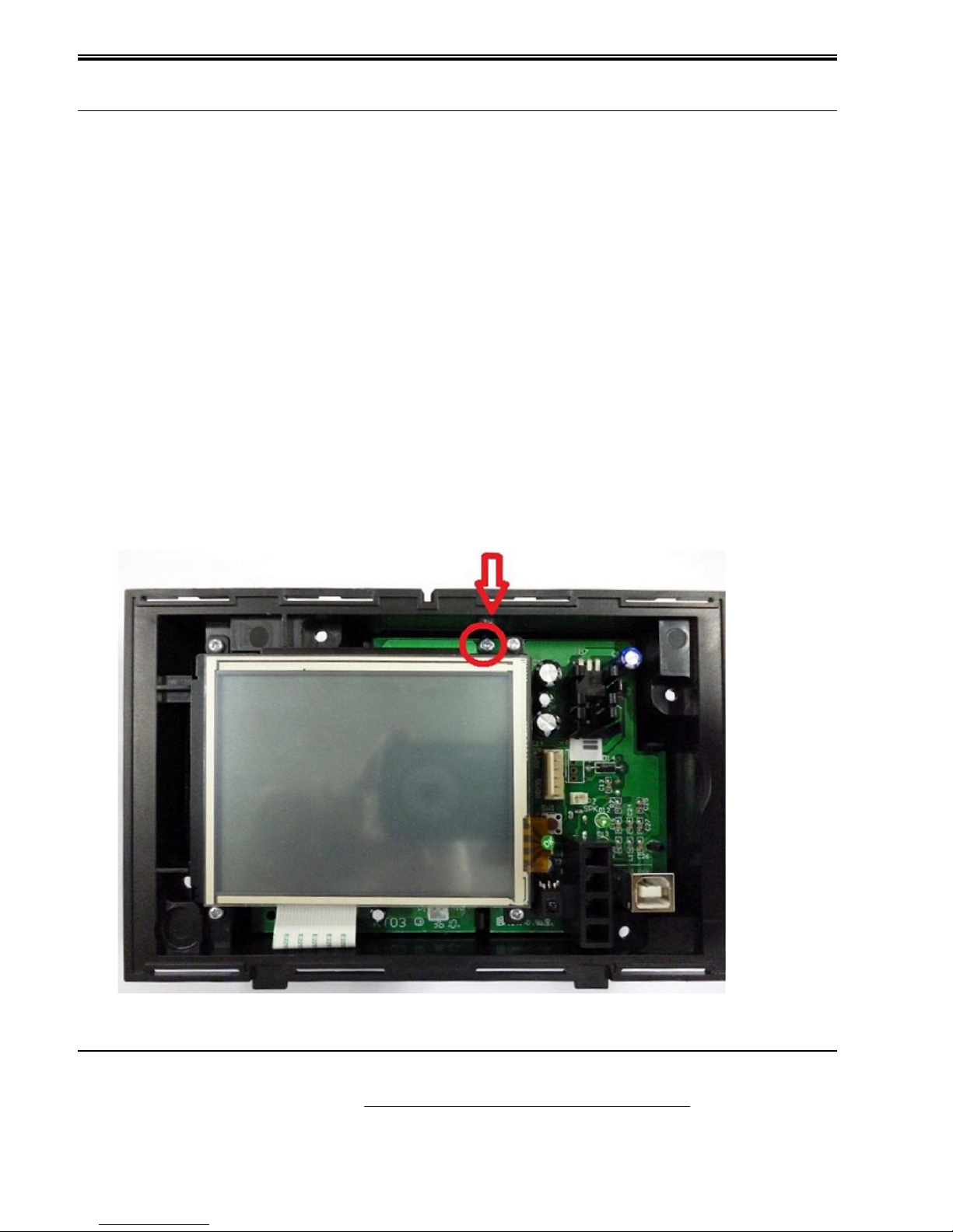
The tamper switch in KT03 may be open. This is behind the KT03 PCB. Check
that the PCB is fully seated onto the plastic catch as shown below.
Programming of KT03
This is covered in a separate manual, the KT03 programming manual which
can be downloaded from http://www.cytech.biz/manuals.html
KT03 Installation Manual
Page 9 of 12
Page 10

KT03 Installation Manual
Page 10 of 12
Page 11

KT03 Installation Manual
Page 11 of 12
Page 12
Document History
Version 1.0.5 - 22 May 2011 Initial Release
Version 1.0.6 - 10 March 2012 Improvements
Version 1.0.7 - 25 March 2012 Added Troubleshooting
Important Note
The printed manual may not always be the most current version. Please
check and download the latest version from
http://www.cytech.biz/manuals.html
The downloaded manual is in A4 size. To print this manual as an A5 Booklet,
on HP PCL printers select Page Scaling = Fit to Printable Area. Select
Properties> Finishing Tab, Document Options = Print on Both Sides, Booklet
Layout = Left Side Binding. Other printers may have different settings to
achieve the same result.
.
KT03 Installation Manual
Page 12 of 12
Copyright Cytech Technology Pte Ltd.
Document Title: KT03 Installation Manual
Version: 1.0.7
Date Last Modified 25 March 2012
web site: http://www.cytech.biz
Email: [email protected]
Forum: http://www.comfortforums.com
 Loading...