


UserInstructions
CyrusSmartPower
IN
C-BUS
R
INPUT
L
CHAIN
Cyrus SmartPower
ab cdefghi1)
MONO OPERATION:
Set ‘mono/stereo’
•
switch to mono.
Connect input to ‘M’.
•
•
Connect speaker
+ve to ‘M+’ and
speaker -ve to ‘M-’.
Refer to manual for details
CAUTION:REPLACE WITH
SAME TYPE FUSE.
ATTENTION:UTILISER UN
FUSIBLE DE RECHANGE DE
MEME TYPE
FUSE: T1A/250V
230V-50/60Hz @ 200W
R
R
+ SPEAKER -
M-
R
R
OUT
MC-BUS
CHAIN INPUT
M
L
MONO
CHAIN
INPUT
IN
R
PRECISION
ELECTRONIC
INSTRUMENT
MADE IN ENGLAND
STEREO
L
- SPEAKER +
L
USE
PSX-R
ONLY
STEREO OPERATION:
Set ‘mono/stereo’
•
switch to stereo.
M+
Connect inputs to ‘L & ’.
•
•
Connect speakers
to ‘-speaker+’ for left &
+speaker-
to ‘ ’ for right.
Refer to manual for details
R
Cyrus CD Player
Fig 1
Fig 2
1% 1^
1&
1$
1#
SmartPower
1!1@
Cyrus FM tuner
R L
Cyrus Pre aCA7.5
Cyrus SmartPower
Fig 3
Left
Right
treble
Right
bass
-
+
+
-
Fig 4a
BI-WIRE
Fig 4b
Input
Left
Input
Right
Input
Right
Input
-
-
-
Left
treble
Left
bass
Left
treble
Right
treble
Fig 4c
-
+
-
Left
Input
Right
Input
Left
treble
-
-
+
Right
treble
-
Left
+
bass
Right
bass
Left
bass
-
-
+
Right
bass
BI-WIRE MONO
BI-AMP
User Instructions Cyrus SmartPower
p
IMPORTANT! Read before operating this equipment!
CAUTION:
to important instructions and safety procedures in this
manual.
ATTENTION:
electrical shock presented by components inside this
roduct. Unauthorised personnel must not open this unit
WARNING:
covers or panels. There are no user serviceable parts in this product.
WARNING:
to rain or moisture.
HEED WARNINGS:
instructions should be adhered to.
READ ALL THE INSTRUCTIONS:
should be read before the product is operated.
RETAIN INSTRUCTIONS:
retained for future reference.
FOLLOW INSTRUCTIONS:
followed.
CLEANING:
liquid or aerosol cleaners. Use a damp cloth for cleaning.
WATER AND MOISTURE:
near a bath tub, wash bowl, kitchen sink, or laundry tub, in a wet basement; or
near a swimming pool and the like. The product must not be exposed to
dripping or splashing and no objects filled with liquids, such as vases, shall be
placed on the product.
HEAT:
radiators, stoves, or any other products (including amplifiers) that produce
heat.
VENTILATION:
to ensure reliable operation of the product and to protect it from overheating
and these openings must not be blocked or covered. The openings should
never be blocked by placing the product on a bed, sofa, rug or similar surface.
This product should not be placed in a built-in installation such as a bookcase
or rack unless proper ventilation is provided or the manufacturer's instructions
have been adhered to.
OBJECT OR LIQUID ENTRY:
product through openings as they may touch dangerous voltage points or
short-out parts that could result in a fire or electric shock.
ACCESSORIES:
bracket, or table. The product may fall, causing serious injury to a child or
adult, and serious damage to the product. Use only with a cart, stand, tripod,
bracket or table recommended by the manufacturer, or sold with the product.
Any mounting of the product should follow the manufacturer's instructions, and
should use a mounting accessory recommended by the manufacturer.
ATTACHMENTS:
manufacturer as they may cause hazards.
MOVING THE PRODUCT:
should be moved with care. Sudden stops, excessive
force, and uneven surfaces may cause the product and
cart to overturn.
POWER SOURCES:
power source indicated on the marking label. If you are not sure of the type of
power supply to your home, consult your product dealer or local power
company. For products intended to operate from battery power, or other
sources, refer to the operating instructions.
OVERLOADING
convenience receptacles. This can result in an increased risk of fire or electric
shock.
The exclamation mark is to draw your attention
The lightning flash warns you of the risk of
.
To reduce the risk of electrical shock do not remove any unit
To reduce the risk of electric shock, do not expose this equipment
All warnings on the product and in the operating
All the safety and operating instructions
The safety and operating instructions should be
All operating and use instructions should be
Unplug this product from the mains before cleaning. Do not use
Do not use this product near water - for example,
The product should be situated away from heat sources such as
Slots and openings in the cabinet are provided for ventilation,
Never push objects of any kind into this
Do not place this product on an unstable cart, stand, tripod,
Do not use attachments not recommended by the product
A product and cart combination
This product should be operated only from the type of
Never overload wall outlets, extension cords, or integral
POWER CORD PROTECTION:
they are not likely to be walked on or pinched by items placed upon
them, paying particular attention to cords at plugs, convenience receptacles,
and the point where they exit from the product.
NAKED FLAMES:
on this product.
LIGHTNING:
when it is left unattended or unused for long periods of time, unplug it from the
wall outlet and disconnect the antenna or cable system. This will prevent
damage to the product due to lightning and power-line surges.
CAUTION! POLARISED CONNECTOR (CANADA and USA):
To prevent electrical shock, match wide blade of plug to wide slot, fully insert.
Do not alter or remove this plug if it does not fit your mains power socket.
Have a suitable socket installed by a competent electrician.
POWER SUPPLY:
Connect the moulded IEC connector of the AC cord supplied plugs into the
power inlet 1@ on the rear of the unit. The mains fuse 1# is on the rear panel
next to the power switch. It must only be replaced as follows:
U.K. / Europe 230V T1A 20mm
N. America / Far East - 115V T2A 20mm
The mains supply requirement for your
label on the rear panel. Before connecting, check that this voltage is the same
as your mains supply.
230V Products: Voltage Range 220V-240V
115V Products: Voltage Range 110V-120V
If you move to an area with a different mains voltage, contact your local
distributor to have your product converted.
No naked flame sources, such as candles, must be placed
For added protection for this product during a lightning storm, or
Power supply cords should be routed so that
or
against
Cyrus SmartPower
is marked on a
Cyrus
NOTE FOR UK CUSTOMERS:
The
SmartPower
mains plug. This plug should not be removed but if it is removed, dispose of it
safely and do not re-use it. To connect a new 13A plug, proceed as follows:
Connect the brown wire to the terminal marked L or coloured red. Connect the
blue wire to the terminal marked N or coloured black. The internal plug fuse
should be 5A.
SERVICING
Do not attempt to service this product yourself as opening or removing covers
may expose you to dangerous voltage or other hazards. Refer all servicing to
qualified service personnel.
CONDITIONS REQUIRING SERVICE:
outlet and refer servicing to qualified service personnel when:
•
•
•
•
•
•
REPLACEMENT PARTS:
service technician has used replacements specified by the manufacturer or
have the same characteristics as the original part. Unauthorised substitutions
may result in fire, electric shock, or other hazards
SAFETY CHECK:
ask the service technician to perform safety checks to determine that the
product is in proper operating condition.
PRODUCT SERVICE CENTRES
For product service or technical advice, contact only authorised
centres. The
is supplied with a power cable terminated by a fused 13A
:
Unplug this product from the wall
When the power supply cord or plug is damaged.
If liquid has been spilled, or objects have fallen into the product.
If the product has been exposed to rain or water.
If the product has been dropped or damaged in any way.
If the product does not operate normally by following the operating
instructions. (Adjust only those controls that are covered by the
operating instructions. Improper adjustment of other controls may
result in damage requiring extensive work by a qualified technician to
restore the product to its normal operation).
When the product exhibits a distinct change in performance.
When replacement parts are required, be sure the
.
Upon completion of any service or repairs to this product,
service
Cyrus
distributors are listed at the end of this instruction manual
Cyrus
GB
GB
1

Cyrus SmartPower User Instructions
Welcome to the world of Cyrus!
Congratulations on your choice of
technology and outstanding quality of manufacture has won countless awards
around the world. We are confident that you will derive great pleasure from
owning a product from one of the most recognised and respected
manufacturers of hi-fi equipment.
Please read these instructions carefully before commencing installation. They
provide full guidance to help you install your
correctly.
Hi-fi products. Our state-of-the-art design
Cyrus
Cyrus SmartPower
safely and
Preparations for Installation
Before installing the
the accessory box.
Guarantee Card (with instruction manual)
•
Power Cable
•
2 MC-Bus phono cables
•
4 speaker plugs
•
After removing these items, please retain the packing.
Install the
temperature, dust or humidity. Never stand the
or on any surface likely to hamper its cooling or ventilation.
SmartPower
SmartPower
in a well ventilated location away from sources of high
check that the following items are included in
SmartPower
under another unit
INSTALLATION
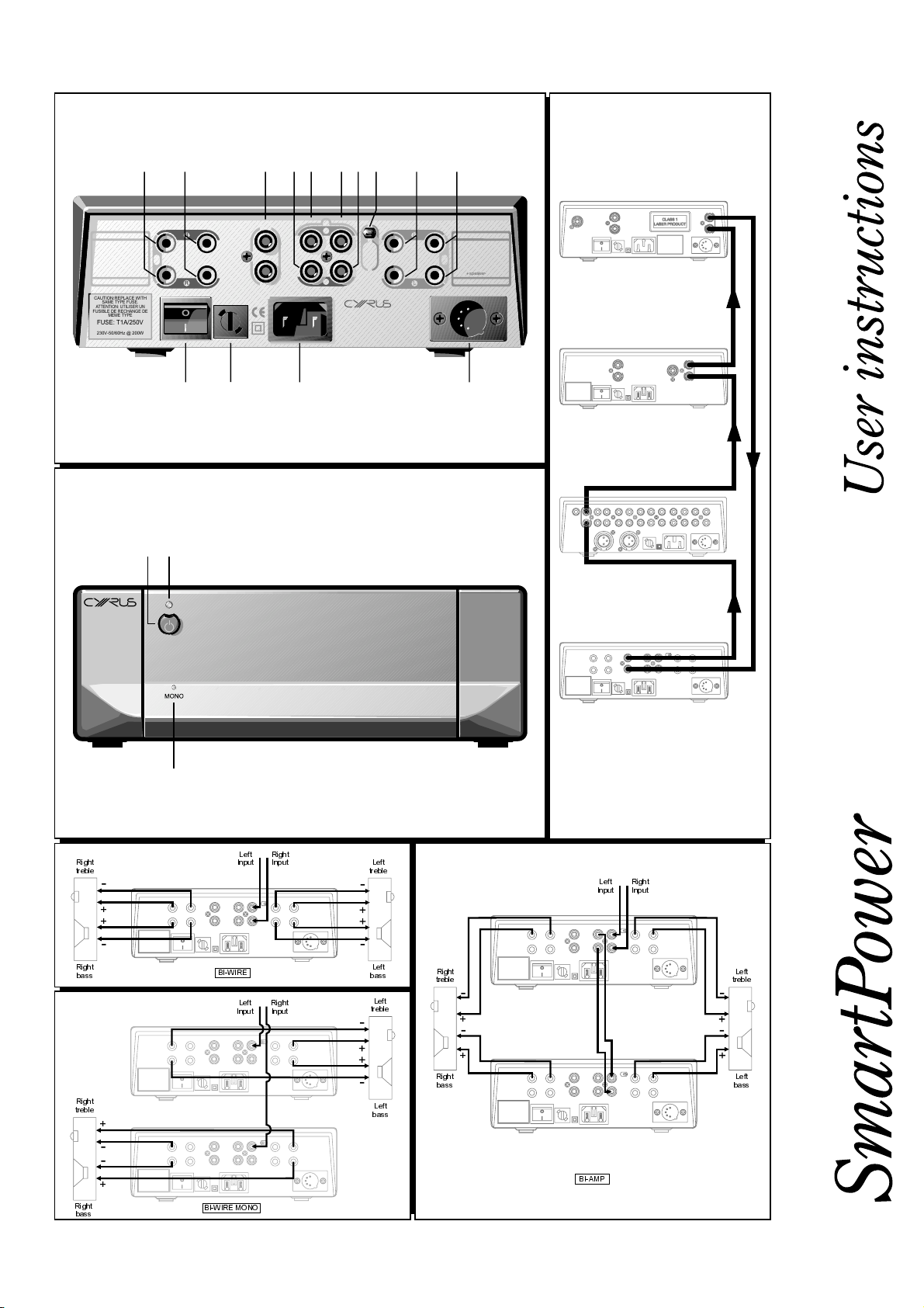
Key to the rear panel drawing
1. Right speaker output + 8. Stereo/Mono selector switch
(- Speaker output mono) 9. Left speaker output -
2. Right speaker output - 10. Left speaker output +
3 MC-Bus Connection (+ Speaker Output mono)
4. Right Chain Output 11. PSX-R Connection
5. Left/Mono Chain Output 12. Power Inlet
6. Left/Mono Input 13. Mains Fuse
7. Right Input 14. Power Switch
(Fig.1)
Connecting to the AC Mains Supply
Connect the socket on the AC Power cable to the Power inlet
the
SmartPower
The mains power switch 1$ on the rear panel of the
on for normal operation, except when left unattended for a long period when it
should be switched off or disconnected from the AC supply
. Now connect the cable to a suitable AC power point.
on the rear panel of
1@
SmartPower
.
should be left
Connecting a Cyrus PSX-R Power Supply (Optional)
Connect the umbilical cord of the
SmartPower 1!
. When correctly fitted, the connector will latch into place.
to the 5-pin input socket of the
PSX-R
Input Connection
Two channel (stereo) operation
Set the STEREO/MONO switch h to Stereo. Connect a stereo phono
interconnect from the output of the preamplifier to the
right inputs
left and right channels correctly ordered.
Single channel (mono) operation
When switched for single channel mono operation, twin
amplifiers are necessary in a stereo system – one for the left and one for the
right channel.
Set the STEREO/MONO switch h on both amplifiers to Mono. Connect a
single phono interconnect from the left output of the preamplifier to the ‘M’
Mono input f of the left channel
preamplifier to the ‘M’ Mono input fof the right channel
and g. Be sure to observe colour coding of the plugs to keep
f
SmartPower
SmartPower's
. Connect the right output of the
SmartPower
left and
SmartPower
.
Loudspeaker Connection
Fitting the speaker plugs
Check for polarity indicators (+ and -) on the loudspeaker cable and fit the
plugs provided. Observe any signal directionality markings indicated on the
cable. If an arrow is printed on the cable it should point toward the
loudspeaker.
If additional or replacement speaker plugs are required for the
ensure that the correct ‘BFA’ type are purchased.
Two channel stereo speaker connections
Connect the left loudspeaker to the rear panel sockets
(black speaker plug) of the
and
i
to the rear panel sockets
the
SmartPower
Dual outputs are provided for the convenient connection of bi-wiring speaker
cables. Figure 4a shows a wiring schematic for a bi-wired stereo system.
Single channel mono speaker connections
Connect the left loudspeaker to the left
marked M+
Repeat this procedure to connect the right channel speaker to the right
channel
using mono amplifiers.
Audio-Visual multi-channel systems
Connect each
channel or single channel instructions above, as appropriate.
.
(red speaker plug) and M- a (black speaker plug).
1)
SmartPower
. Fig 4b shows a wiring schematic for a bi-wired system
SmartPower
SmartPower
red speaker plug) and
a
SmartPower
in turn to the system speakers, following the two
. Connect the right loudspeaker
(black speaker plug) of
b
using the panel sockets
SmartPower
(red speaker plug)
1)
Two channel or Single channel high power operation
The
SmartPower
or as a single channel (mono) amplifier for higher power applications. The
SmartPower
Stereo systems
Stereo systems may be set up with either a single
channel (stereo) operation or twin
operation.
Audio-Visual multi-channel systems
Both two channel and single channel high power modes may be employed for
the multiple channel requirements of audio-visual systems. Two channel and
single channel amplifiers may also be mixed in these systems if preferred, for
example- three
to drive the Front Left, Right and Centre channels and a single Two channel
(stereo) amplifier to drive both the left and right surround channels.
Note:
Ensure all equipment is disconnected from the power before any
connections or disconnections are made.
2
may be configured as either a two channel (stereo) amplifier
is factory set for stereo operation.
set for two
SmartPower
SmartPower
SmartPowers
amplifiers set for single channel (mono) operation
set for single channel (mono)
GB
GB

User Instructions Cyrus SmartPower
Bi-amplification
For convenience of connection in applications such as Bi-Amplification the
Chain outputs e and d allow more than one
a Pre-Amplifier.
The Chain facility can be used with two or more
amping by connecting the Chain output of the first
the next
SmartPower
separate power amplification for the bass and treble units of the loudspeakers.
When adding additional
phono interconnect from the Chain output RCA jacks e and d to the inputs
and g of the new
f
installations, connect the ‘M’ chain output e of each Mono amplifier to the ‘M’
Mono inputs f of the new amplifiers.
When the input connections to the new amplifier are complete, separate
connections may be made to the bass and treble units of the system
speakers. Fig 4c shows a wiring schematic for a bi-amped system using
stereo amplifiers.
. Such a system provides the sonic benefits of totally
SmartPowers
SmartPower
SmartPower
to a system, connect a quality RCA
. For single channel (mono) chain
to be connected to
SmartPowers
SmartPower
for Bi/Tri-
to the inputs of
MC-Bus connection
Connecting the MC-BUS sockets c of the
provides unified system power control. An MC-BUS loop is established by
connecting single phono cables from the MC-BUS output of one unit to the
MC-BUS input of another in a daisy-chain. Complete the loop by returning the
MC-BUS output of the final component to the MC-BUS input of the first (see
example system connections in Fig.3).
With MC-BUS established you can control the power function of the system
from the front panel or remote control of the main
Processor.
SmartPower
in an MC-BUS system
amplifier or Surround
Cyrus
OPERATION
Key to the front panel drawing
15. Standby Switch
16. Standby Light
17. Mono Light
Switching On
The mains power switch 1$ on the rear panel of the
on for normal operation, except when left unattended for a long period when it
should be switched off or disconnected from the AC supply.
When power is applied, the STANDBY key 1% may be used for power control.
The Standby light 1^ shows red when the
when operational.
In addition to manual power control from the STANDBY key, the
also features a music sensing automatic power control which listens for the
presence of an input signal and will switch on if music begins to play. If the
SmartPower
after the music has stopped.
Remote power control can also be enabled by connecting the MC-Bus sockets
of the SmartPower to a
c
Integrated amplifier or Surround decoder. A number of
connected in this way to provide remote standby control of all the system
power amplifiers.
has been activated in this way it will reset to Standby five minutes
(Fig.2)
SmartPower
SmartPower
system which includes a Preamplifier,
Cyrus
is in Standby and green
SmartPowers
should be left
SmartPower
may be
FRONT PANEL INDICATORS
MONO Indicator
The MONO Indicator 1& will glow red if the rear panel STEREO/MONO switch
is set for MONO Operation. This switch can be operated only when the
h
SmartPower
indication system
is in Standby. Operating it at any other time activates the fault
.
GB
GB
3

Cyrus SmartPower User Instructions
TROUBLESHOOTING GUIDE
If your
SmartPower
all connections using the notes in this manual. If problems persist, the
checklists below may help.
If you are in any doubt, consult your dealer.
No sound from either speaker
Preamplifier mute switch is on Deselect Mute
Loudspeakers are disconnected Check speaker connections
Fault indication on the front panel of
your
SmartPower
No sound from one loudspeaker
Does your speaker have fuses? Check speaker, replace fuses
Speaker cables or interconnects
faulty
Mono installations: Check connections are correct to
Poor quality sound in two channel stereo mode
Selector switch incorrectly set to
mono
Poor quality sound in single channel mono mode
Selector switch incorrectly set to
stereo
Speakers plugs not connected to the
correct terminals
is not operating properly, disconnect the power and check
See ‘Fault Indication System’
Check connections, cables - replace
if needed
input and output of both amplifiers.
Set the switch to stereo
Set the switch to mono
Check all speaker connections
carefully
FAULT INDICATION SYSTEM
The
SmartPower
designed to prevent damage to your hi-fi system and help you diagnose a
possible problem. If a fault persists, reset the amplifier via the rear panel
mains switch.
has a powerful protection system and fault indication system
FAULT INDICATIONS
Standby light flashing Green / Yellow
This indicates overload in at least
one channel. If the problem is
temporary (e.g. excessive volume),
normal operation will resume after
ten seconds. If the fault indication
persists, there may be a problem
with the speakers or connections.
Standby light flashing Green
A fault has been reported from the
PSX-R
The
switched off.
Standby light flashing Yellow / Red
The
MONO light flashing
The STEREO/MONO switch has
been changed whilst the amplifier is
operating.
If after taking remedial measures a fault condition remains, you should return
the
Centre.
is disconnected or
PSX-R
SmartPower
SmartPower
has over heated.
to your
Cyrus
Switch off the power at the rear panel
and unplug the speaker cables. If the
fault indication clears when power is
re-applied, check the loudspeakers,
cables and plugs for loose strands of
wire causing a possible short circuit.
Switch off the power to the
SmartPower
on again. If the problem does not
clear, return both units to your
distributor for checking.
Check there is power to the
and check the PSX-R connection to
the
Check the ventilation around the
SmartPower.
down before re-applying power.
Return the switch to its original
position.
appointed dealer or an authorised Service
and the
SmartPower.
Allow the unit to cool
PSX-R
Switch
Cyrus
PSX-R
WARRANTY
The warranty card enclosed should be completed by the Dealer and the
purchaser and returned to
No Dealer or Distributor may vary the terms of this warranty which is personal
to the original Purchaser and is not transferable.
Please retain the sales receipt as proof of purchase.
Warranty claims must wherever possible be made through the Dealer from
whom the equipment was purchased.
This warranty excludes:
Damage caused through neglect, accident, misuse, wear and tear, or
•
through incorrect installation, adjustment or repair by unauthorised
personnel. Any unauthorised servicing will result in loss of guarantee.
Liability for damage or loss occurring in transit to or from the purchaser.
•
Consequential damage, loss or injury, arising from or in conjunction with
•
this equipment.
Equipment for attention under warranty should be consigned return carriage
paid. If returned equipment is found to comply with the published specification,
reserves the right to raise a charge.
CYRUS
The above conditions do not affect your statutory rights as a consumer.
or its Distributor within 8 days of purchase.
CYRUS
SPECIFICATIONS
Power Supply
Voltage: ...........................................................................As plate on rear of unit
Power Consumption
Standby ..........................................................................................................6W
ON (No Load) ...............................................................................................23W
ON (2 x 60W/Ch)........................................................................................185W
Safety Requirements...........................................................................EN 60065
Enclosure
Dimensions (WxHxD)............................................................215 x 75 x 365mm
Weight ........................................................................................................4.3Kg
Material...................................................................................... Die cast chassis
Audio Performance
Input Sensitivity (60W/8Ω)..............................RCA............................... 413mV
Input Impedance ............................................. RCA ..................................20k
Channel Balance ........................................................................................0.1dB
Frequency Response ..................................... (-3dB)..................... 1Hz-100kHz
Signal to Noise Ratio (A-WTD)........................ (Unwtd)............................102dB
(Ref 60W) (A-wtd) .............................112dB
Signal to Noise Ratio (A-WTD)........................ (Unwtd)..............................85dB
(Ref 1W) (A-wtd) ...............................94dB
Output Power Stereo (Internal PSU) ............... 8 Ohms...............................60W
Output Power Mono (Internal PSU)................. 8 Ohms .............................105W
Output Power Stereo (with PSX-R)................. 8 Ohms ...............................60W
Output Power Mono (with PSX-R)................... 8 Ohms.............................125W
THD+N (@ 2/3 full power)............................... (20Hz-20kHz)...................0.01%
1kHz...............................0.004%
Cyrus reserves the right to change specifications without notice. E&OE.
Ω
GB
4
GB

Gebrauchsanleitung Cyrus SmartPower
WICHTIGE HINWEISE! Unbedingt vor Benutzung des
Gerätes lesen!
VORSICHT:
besonders wichtige Bedienungs- und Sicherheitshinweise in dieser
Anleitung lenken.
ACHTUNG:
elektrischen Schlages durch Bauteile im Innern des Gerätes hin.
Öffnen des Gerätes nur durch fachkundiges Personal.
Warnung:
Abdeckungen oder Gehäusewände dieses Geräts nicht entfernt werden. Das
Produkt enthält keine vom Benutzer zu wartenden Teile.
Warnung:
Gerät weder Regen noch Feuchtigkeit ausgesetzt werden.
BEACHTEN SIE DIE VORSICHTSHINWEISE:
und in der Gebrauchsanleitung müssen beachtet werden.
LESEN SIE ALLE ANLEITUNGEN:
Betrieb müssen vor der Benutzung des Gerätes gelesen werden.
BEWAHREN SIE DIE ANLEITUNGEN AUF:
zum Betrieb müssen zum Nachlesen aufbewahrt werden.
BEFOLGEN SIE DIE ANWEISUNGEN:
Betrieb müssen befolgt werden.
REINIGUNG:
Reinigungsmittel oder Sprays verwenden. Das Gerät mit einem angefeuchteten
Tuch reinigen.
WASSER UND FEUCHTIGKEIT:
Nähe von Wasser, z. B. Badewanne, Waschbecken, Spüle, Waschkübel, im
feuchten Keller oder in der Nähe eines Swimmingpools oder dergleichen. Das
Gerät darf niemals tropfenden oder spritzenden Flüssigkeiten ausgesetzt werden.
Stellen sie keinesfalls Vasen oder andere flüssigkeitsgefüllte Behälter auf das
Gerät.
WÄRME:
Heizungskörpern, Heizgeräten, Öfen oder von anderen wärmeerzeugenden
Produkten (einschließlich Verstärkern) aufgestellt werden.
LÜFTUNG:
den ausfallsicheren Betrieb des Produkts sicherstellt und es vor übermäßiger
Erwärmung schützt. Diese Öffnungen dürfen nicht blockiert oder verdeckt werden.
Aus dem Grund darf das Produkt nicht auf ein Bett, ein Sofa, einen Teppich oder
eine ähnliche weiche Oberfläche gestellt werden. Das Produkt eignet sich nicht für
den Einbau in ein Bücherregal oder ein Gestell, es sei denn, für eine
ausreichende Belüftung ist gesorgt und die Anweisungen des Herstellers werden
eingehalten.
EINDRINGEN VON GEGENSTÄNDEN ODER
Öffnungen dürfen keinerlei Gegenstände in das Gerät eingeschoben werden, da
diese gefährliche Spannungspunkte berühren oder Teile kurzschließen könnten,
was einen Brand oder elektrischen Schlag verursachen kann.
ZUBEHÖR:
Ständer, Stativ oder Tisch oder bringen Sie es nicht an einer instabilen Halterung
an. Es kann herunterfallen, wobei Personen verletzt werden und Schäden am
Produkt entstehen können. Verwenden Sie nur Rollwagen, Ständer, Stative,
Halterungen oder Tische, die vom Hersteller empfohlen oder die mit dem Produkt
verkauft werden. Bei der Wandmontage des Produkts sind die Anweisungen des
Herstellers zu befolgen und das vom Hersteller empfohlene Zubehör ist zu
verwenden.
ZUSATZGERÄTE:
empfohlen werden, da Gefahren entstehen können.
TRANSPORT:
wird, ist Vorsicht geboten. Durch plötzliches Anhalten,
übermäßige Gewaltanwendung und unebenen Boden kann der
Wagen mit dem Produkt umstürzen.
NETZSPANNUNG:
angegebenen Netzspannung betrieben werden. Wenn Sie nicht wissen, welche
Netzspannung bei Ihnen vorliegt, wenden Sie sich an Ihren Fachhändler oder Ihr
Elektrizitätswerk. Hinweise zu den Produkten, die mit Batterie oder anderen
Stromquellen betrieben werden, entnehmen Sie der Bedienungsanleitung.
ÜBERLAST:
dürfen nicht überlastet werden, da dies die Gefahr eines Brandes oder
elektrischen Schlages verursachen kann.
Das Ausrufungszeichen soll Ihre Aufmerksamkeit auf
Das Blitzzeichen weist Sie auf die Gefahr eines
Um die Gefahr eines elektrischen Schlages zu vermeiden, dürfen die
Um die Gefahr eines elektrischen Schlages zu vermeiden, darf dieses
Alle Vorsichtshinweise am Produkt
Alle Anweisungen zur Sicherheit und zum
Die Anweisungen zur Sicherheit und
Alle Anweisungen zur Sicherheit und zum
Vor der Reinigung den Netzstecker ziehen. Keine flüssigen
Verwenden Sie dieses Produkt nicht in der
Das Produkt darf nicht in der Nähe von Wärmequellen wie
Die Schlitze und Öffnungen im Gehäuse dienen zur Belüftung, welche
FLÜSSIGKEITEN:
Stellen Sie dieses Produkt nicht auf einen instabilen Rollwagen,
Verwenden Sie keine Zusatzgeräte, die nicht vom Hersteller
Wenn das Produkt auf einem Wagen transportiert
Dieses Produkt darf nur mit der auf dem Geräteschild
Wandsteckdosen, Verlängerungskabel oder integrierte Steckdosen
Durch die
NETZKABELSCHUTZ:
Darüberlaufen oder Einklemmen durch Gegenstände verhindert wird. Besonders
ist auf die Abschnitte des Kabels in der Nähe eines Steckers, einer Steckdose
oder der Austrittsstelle aus dem Gerät zu achten.
OFFENE FLAMME:
das Gerät gestellt werden.
BLITZSCHUTZ:
unbeaufsichtigt oder unbenutzt bleibt, ziehen Sie als zusätzliche
Schutzmaßnahme den Netzstecker und trennen Sie die Antenne oder das
Kabelsystem. Damit werden Schäden durch Blitz oder Spannungsstöße
verhindert.
VORSICHT! GEPOLTER STECKER (NUR IN DEN USA UND KANADA):
Zur Verhinderung eines elektrischen Schlages muss der flache Steckerstift in den
breiten Schlitz der Steckdose eingesteckt werden. Den Stecker ganz einstecken.
Wenn der Stecker nicht in Ihre Netzsteckdose passt, dürfen Sie diesen nicht
ändern oder abtrennen. Lassen Sie von einem ausgebildeten Elektriker eine
geeignete Steckdose installieren.
Netzkabel müssen so verlegt werden, dass ein
Keine offenen Flammenquellen wie z. B. Kerzen dürfen auf
Bei Gewittern oder wenn das Produkt längere Zeit
NETZVERSORGUNG:
Der eingekerbte IEC-Stecker des mitgelieferten Netzkabels gehört in den
entsprechenden Anschluss 1@ auf der Rückseite des Geräts. Die Netzsicherung 1#
befindet sich ebenfalls auf der Rückseite neben dem Netzschalter. Sie darf
ausschließlich durch folgende Typen ersetzt werden:
Großbritannien / Europa - 230 V T1A 20 mm
Nordamerika / Fernost - 115 V T2A 20 mm
Die vorgeschriebene Betriebsspannung ist auf einem rückseitigen Aufkleber
angegeben. Stellen Sie vor dem Anschluss sicher, daß diese Ihrem örtlichen
Stromnetz entspricht, z. B.
230V Produkte: Spannungsbereich von 220 V-240 V
115V Produkte: Spannungsbereich von 110 V-120 V
Wenn Sie in eine andere Region mit unterschiedlicher Netzspannung umziehen,
wenden Sie sich an Ihren Cyrus Vertrieb, um die Anpassung des Geräts
vorzunehmen.
REPARATUREN:
Versuchen Sie nicht, dieses Produkt selbst zu reparieren oder die Verkleidungen
zu entfernen, da Sie sich dadurch Hochspannung oder anderen Gefahren
aussetzen würden. Überlassen Sie alle Reparaturen den Fachleuten.
BEDINGUNGEN, DIE REPARATUREN ERFORDERN:
Netzstecker und beauftragen Sie den Kundendienst mit der Reparatur des
Gerätes, wenn:
•
Netzkabel oder -stecker beschädigt sind
• Flüssigkeit oder Gegenstände in das Gerät eingedrungen sind
•
das Gerät Regen oder Wasser ausgesetzt wurde
• das Gerät heruntergefallen oder anderweitig beschädigt ist
• das Gerät unter Befolgung der Bedienungsanleitung nicht normal
funktioniert. Verstellen Sie nur die Regler, die in der
Bedienungsanleitung beschrieben werden. Das unsachgemäße
Verstellen von anderen Reglern kann Schäden verursachen und
aufwendige Reparaturen durch einen qualifizierten Techniker erfordern,
um das Gerät wieder in seinen normalen Betriebszustand zu versetzen.
•
das Produkt eine deutliche Leistungsminderung aufweist - in dem Fall ist
eine Reparatur notwendig.
ERSATZTEILE:
dass der Techniker Ersatzteile verwendet, die vom Hersteller angegeben werden
oder die die gleichen Eigenschaften wie die Originalteile aufweisen. Unzulässige
Ersatzteile können Brände, elektrischen Schlag oder andere Gefahren
verursachen.
SICHERHEITSKONTROLLE:
Wartungs- oder Reparaturarbeiten Sicherheitskontrollen durchzuführen, um den
ordnungsgemäßen Betriebszustand des Gerätes zu bestätigen.
KUNDENDIENSTZENTRALEN
Wenn Ersatzteile erforderlich sind, sollten Sie sich vergewissern,
Bitten Sie den Techniker, im Anschluss an
:
Wenden Sie sich bei Fragen zum Produktservice oder bei technischen Problemen
nur an autorisierte Cyrus-Kundendienstzentralen. Eine Liste der Hauptzentralen
finden Sie auf der hinteren Umschlagseite dieser Bedienungsanleitung.
Ziehen Sie den
D
D
5

Cyrus SmartPower Gebrauchsanleitung
Willkommen in der
Vielen Dank, daß Sie sich für Produkte aus der Cyrus-Serie entschieden
haben. Mit „state-of-the-art“ Konzeptionen und hervorragender Produktqualität
konnten wir weltweit zahllose Preise gewinnen. Wir sind sicher, dass Ihnen
dieses Gerät – von einem der anerkanntesten HiFi-Hersteller – immer viel
Freude bereiten wird.
Lesen Sie bitte diese Anweisungen sorgfältig durch, bevor Sie mit der
Installation beginnen. So können Sie Ihren Cyrus SmartPower sicher und
korrekt in Betrieb nehmen.
Cyrus
Welt!
Vorbereitung der Installation
Bevor Sie Ihren SmartPower in Betrieb nehmen, überprüfen Sie bitte, ob sich
die folgenden Teile in der Zubehör-Schachtel befinden:
Garantiekarte (mit Bedienungsanleitung)
•
Netzkabel
•
2 x Cinch-Kabel für MC-BUS Verbindung
•
4 Lautsprecherstecker
•
Bewahren Sie die Verpackung nach dem Auspacken auf.
Bauen Sie Ihren SmartPower an einem ausreichend belüfteten Platz auf – in
angemessener Entfernung von starken Wärmequellen, geschützt vor Staub
und Feuchtigkeit. Stellen Sie den SmartPower niemals unter ein anderes
Gerät oder auf irgendeine Oberfläche, die die Kühlung durch Verstopfen der
Ventilationsöffnungen behindern könnte.
INSTALLATION
Erklärung der Nummern auf der Rückseite des SmartPower:
1. Rechter Lautsprecher (+) 8.
und Mono-Lautsprecher ( - ) 9. Linker Lautsprecher ( - )
2. Rechter Lautsprecher ( - ) 10. Linker Lautsprecher (+)
MC-BUS-Anschluss
3
4. Parallel-Ausgang rechts 11.
5. Parallel-Ausgang links / Mono 12.
6. Eingang links / Mono 13.
7. Eingang rechts 14.
(siehe Abbildung 1 des Faltblattes)
STEREO / MONO-Umschalter
und Mono-Lautsprecher (+)
Cyrus-PSX-R-Anschluss
Stromanschluss
Netzsicherung
Netzschalter
Anschluss an die Netzversorgung
Stecken Sie die Buchse des mitgelieferten Netzkabels in den rückseitigen
Netzanschluss 1@ des SmartPower. Dann stecken Sie den Netzstecker in die
Steckdose.
Der Netzschalter 1$ auf der Rückseite des SmartPower sollte normalerweise
eingeschaltet bleiben, es sei denn Sie nutzen das Gerät über längere Zeit
nicht. In diesem Fall sollten Sie ausschalten oder den Netzstecker ziehen.
Anschluss eines
Verbinden Sie das festangelötete Kabel des PSX-R mit der fünfpoligen
Cannon-Buchse des Cyrus Power. Bei korrekter Ausrichtung rastet der
Stecker mit einer Lasche ein.
Cyrus PSX-R
Netzteils
Signaleingänge
Zweikanalbetrieb (Stereo)
Stellen Sie den STEREO/MONO Schalter h auf Stereo. Verbinden Sie den
Ausgang des Vorverstärkers über eine Stereo-Tonleitung mit dem linken und
rechten Eingängen f and g des SmartPower. Achten Sie auf die
Farbcodierung der Stecker, um die Kanäle nicht zu vertauschen.
High-Power Mono-Betrieb
Werden die SmartPower-Einheiten als Mono-Geräte betrieben, sind zur
Stereo-Wiedergabe zwei Verstärker erforderlich - einer für den linken und
einer für den rechten Kanal.
Stellen Sie den STEREO/MONO Schalter h bei beiden Geräten auf Mono.
Verbinden Sie den Ausgang des linken Kanals am Vorverstärker über eine
einzelne Tonleitung mit dem ‘M’ Mono Eingang f des für den linken Kanal
vorgesehenen SmartPower. Verbinden Sie den Ausgang des rechten Kanals
am Vorverstärker über eine einzelne Tonleitung mit dem ‘M’ Mono Eingang
des für den rechten Kanal vorgesehenen SmartPower.
Lautsprecher-Anschluss
Lautsprecher-Stecker befestigen
Orientieren Sie sich über Polaritätsmarkierungen (+ und -) auf dem
Lautsprecherkabel und montieren Sie die mitgelieferten Stecker. Beachten Sie
eine eventuell vorgegebene Signalfluss-Richtung auf dem Lautsprecherkabel.
Entsprechende Pfeile sollten in Richtung Lautsprecher zeigen.
Sollten Sie weitere Lautsprecherstecker für den SmartPower benötigen,
achten Sie beim Kauf auf die passende Type ‘BFA’.
Lautsprecher-Anschluss für Stereo-Betrieb
Verbinden Sie den linken Lautsprecher mit den Klemmen 1) (roter Stecker)
(schwarzer Stecker) am SmartPower. Verbinden Sie den rechten
und
i
Lautsprecher mit den Klemmen a (roter Stecker) und
am SmartPower.
Zum bequemen Anschluss von Bi-Wiring sind die Lautsprecher-Ausgänge
doppelt vorhanden. Abb. 4a zeigt die Verkabelung eines Stereo-Sytems mit
Bi-Wiring.
Lautsprecher-Anschluss für Mono-Einkanal-Betrieb
Verbinden Sie den linken Lautsprecher mit dem für den linken Kanal
vorgesehenen SmartPower. Benutzen Sie die mit M+ 1) bezeichneten
Ausgangsklemmen (roter Stecker) und M- a (schwarzer Stecker).
Verbinden Sie den rechten Lautsprecher auf die gleiche Weise mit dem für
den rechten Kanal vorgesehenen SmartPower.
eines Stereo-Sytems mit Bi-Wiring unter Verwendung von Mono-Verstärkern.
Abb. 4b zeigt die Verkabelung
Mehrkanal-AV-Anlagen
Verbinden Sie jede der SmartPower -Einheiten mit dem zugeordneten
Lautsprecher, und gehen Sie dabei sinngemäß so vor, wie in den beiden
vorstehenden Abschnitten beschrieben.
(schwarzer Stecker)
b
f
Stereo-Systeme
Stereo-Systeme können mit einem einzelnen SmartPower im Zweikanal-
Betrieb (Stereo) oder mit zwei SmartPower-Einheiten im Doppel-Mono-Betrieb
aufgebaut werden.
Mehrkanal-AV-Anlagen
Für mehrkanalige AV-Anlagen stehen ebenfalls beide Möglichkeiten zur Wahl:
normaler Stereo-Betrieb oder Doppel-Mono-Betrieb mit erhöhter Leistung. In
solchen Anlagen können beide Betriebsarten auch gemischt eingesetzt
werden: High-Power Mono-Betrieb z.B. für jeden der drei Frontkanäle (links,
Mitte, rechts) und ein einzelner Zweikanal (Stereo)-Verstärker für die beiden
rückwärtigen Surround-Kanäle.
Hinweis:
Anschlussarbeiten ausführen!
Trennen Sie die Netzverbindung aller Geräte, während Sie
6
D
D

Gebrauchsanleitung Cyrus SmartPower
Bi-Amping"
"
Zur Erleichterung der Verkabelung bei besonderen Betriebsarten wie "BiAmping" gestatten die Parallel-Ausgänge e und d den Anschluss von mehr
als einem SmartPower an den steuernden Vorverstärker.
Das "Durchschleifen" des Eingangssignals ermöglicht den Anschluss von zwei
oder mehr SmartPower-Einheiten für Bi- oder Tri-Amping. Die ParallelAusgänge des ersten SmartPower werden mit den Eingängen des nächsten
SmartPower verbunden.. Ein solches System bringt die klanglichen Vorteile
total getrennter Leistungsverstärkung für Tief- und Hochtöner der angeschlossenen Lautsprecher zur Geltung.
Wenn weitere SmartPower-Einheiten angeschlossen werden sollen, werden
die Parallel-Ausgänge e und d mit den Eingängen f und g des neuen
SmartPower verbunden. Bei Mono-Einkanal-Betrieb wird zum "Durchschleifen" des Vorverstärker-Signals der M’ Mono Parallel-Ausgang e des
jeweiligen Mono-Verstärkers mit dem ‘M’ Mono Eingang f des neuen
Verstärkers verbunden.
Wenn die Eingänge des neuen Verstärkers richtig angeschlossen sind,
können die separaten Leitungsverbindungen zu den Tief- und Hochtönern der
Lautsprecher hergestellt werden. Abb. 4c zeigt die Verkabelung eines
Systems mit "Bi-Amping" unter Verwendung von Stereo-Endverstärkern.
MC-BUS-Anschlüsse
Die Einbeziehung der MC-BUS-Buchsen c am SmartPower in ein MC-BUS
System ermöglicht ein zentrales Schalten der gesamten Anlage. Eine MCBUS-Schleife kann mit einfachen (Mono-) Tonleitungen hergestellt werden,
indem der MC-BUS-Ausgang eines Gerätes mit dem MC-BUS Eingang des
nächsten Gerätes verbunden wird. Die Schleife ist geschlossen, wenn der
MC-BUS-Ausgang des letzten Gerätes und der MC-BUS-Eingang des ersten
Gerätes miteinander verbunden sind. (Siehe Anschlussbeispiel in Abb. 3.)
Der vollständig verkabelte MC-BUS gestattet das zentrale Ein- und Ausschalten der gesamten Anlage von der Frontplatte oder der Fernbedienung
eines Cyrus-Verstärkers oder Surround-Prozessors aus.
Betrieb
Erklärung der Zahlen auf der Frontplatte des Cyrus SmartPower
15. Standby-Taste
16. Standby-Anzeige
17. Mono-Anzeige
(siehe Seite 2 der Ausklappseite)
Einschalten
Der Netzschalter 1$ an der Rückseite des SmartPower sollte bei normaler
Benutzung des Gerätes stets eingeschaltet bleiben. Bei längerer Abwesenheit
jedoch sollte das Gerät ausgeschaltet oder vom Netz getrennt werden.
Bei eingeschaltetem Netz kann die STANDBY-Taste 1% zum Ein- und
Ausschalten benutzt werden. Die Standby-Anzeige 1^ leuchtet rot, wenn der
SmartPower in 'Standby' ist, und wechselt zu grün, sobald er eingeschaltet
wird.
Neben der STANDBY-Taste verfügt der SmartPower noch über eine signal-
gesteuerte Einschalt-Automatik, die das Eintreffen eines Musiksignals zum
Einschalten des Verstärkers nutzt. Wurde der SmartPower auf diese Weise
aktiviert, schaltet er sich auch fünf Minuten nach dem Ende der Wiedergabe
wieder auf Standby.
Ein- und Ausschalten per Fernbedienung ist möglich, wenn zuvor die MCBUS-Buchsen c des SmartPower mit einem Cyrus-System verbunden
wurden, das entweder einen Vorverstärker, einen Vollverstärker oder einen
Surround-Decoder enthält. Auch weitere SmartPower-Einheiten können auf
diese Weise angeschlossen und in die Fernschaltung der Gesamtanlage mit
einbezogen werden.
ANZEIGELEUCHTEN AN DER FRONTPLATTE
Mono-Anzeige
Die Mono-Anzeige 1& leuchtet rot, wenn der STEREO / MONO - Schalter
an der Rückseite des Gerätes in Stellung MONO steht. Dieser Schalter darf
nur betätigt werden, wenn der SmartPower sich im 'Standby'-Zustand
befindet. Andernfalls wird das Fehler-Erkennungssystem aktiviert.
h
D
D
7

Cyrus SmartPower Gebrauchsanleitung
HINWEISE ZUR FEHLERSUCHE
Sollte Ihr Cyrus Power nicht korrekt arbeiten, ziehen Sie bitte den Netzstecker
ab und überprüfen Sie sämtliche Anschlüsse unter Zuhilfenahme der
Bedienungsanleitung. Sollte der Fehler bestehen bleiben, hilft vielleicht die
folgende Fehlersuche.
Im Zweifelsfall wenden Sie sich bitte an Ihren Händler.
Kein Ton aus beiden Lautsprechern
Die Mute-Taste des Vorverstärkers ist
aktiviert
Lautsprecher sind nicht angeschlossen Lautsprecher-Anschlüsse überprüfen
Fehler-Indikation auf der Frontplatte
Ihres SmartPower
Kein Ton aus einem der Lautsprecher
Sind die Lautsprecher mit Sicherungen
ausgestattet?
Lautsprecheranschlüsse oder Kabel
beschädigt
Mono-Betrieb Prüfen Sie, ob die Ein- und Ausgänge
Schlechte Tonqualität in Betriebsart Stereo
Wahlschalter steht auf MONO Auf STEREO umschalten
Schlechte Tonqualität bei Mono-Einkanal-Betrieb
Wahlschalter steht auf STEREO Auf MONO schalten
Lautsprecher nicht an die richtigen
Klemmen angeschlossen
Dekativieren Sie Muting
Siehe „Fehler-Indikator“
Prüfen Sie die Lautsprecher – ersetzen
Sie die Sicherungen falls nötig
Prüfen Sie die Anschlüsse und Kabel,
ersetzen Sie diese falls nötig
beider Verstärker richtig angeschlossen sind
Überprüfen Sie sorgfältig alle
Lautsprecheranschlüsse
FEHLER-INDIKATOR
Der SmartPower besitzt ein einzigartiges, leistungsfähiges Schutz- und
Fehlererkennungssystem. Es wurde geschaffen, um den Verstärker und die
angeschlossenen Geräte wirkungsvoll vor Beschädigungen zu bewahren und
bei der Fehlerfindung zu helfen. Nach der Anzeige eines Fehlers auf der
Frontplatte, müssen Sie das Fehlererkennungssystem durch Betätigung des
Hauptschalters auf der Rückseite zurückstellen.
FEHLER-ANZEIGE
Standby - Leuchte blinkt grün / gelb
Das zeigt eine Überlastung in einem
oder beiden Kanälen an. Wenn es sich
um ein temporäres Problem handelt
(z. B. zu weit aufgedrehte Lautstärke),
geht der Cyrus Power nach 10
Sekunden wieder in normalen Betrieb
über. Bleibt das Problem bestehen,
handelt es sich wahrscheinlich um
einen Fehler des Lautsprechers oder
seiner Anschlüsse.
Standby - Leuchte blinkt grün
Ein Fehler wird am PSX-R angezeigt. In diesem Fall schalten Sie beiden
Das PSX-R ist abgeschaltet oder nicht
angeschlossen.
Standby - Leuchte blinkt gelb / rot
Das zeigt eine Überhitzung des Cyrus
Power an.
Das MONO - Lämpchen blinkt
Das zeigt an, dass der STEREO-/
MONO-Umschalter während des
Betriebs betätigt wurde.
Schalten Sie die Netzversorgung auf
der Rückseite des SmartPower ab und
ziehen Sie die Lautsprecherkabel.
Erlicht der Fehler-Indikator nun beim
Wiedereinschalten der Netzspannung,
checken Sie Ihre Lautsprecher,
Lautsprecherkabel und
Anschlussstecker nach Fehlern.
Möglicherweise haben blanke Litzen
einen Kurzschluss verursacht.
Geräten kurz den Strom ab und dann
wieder an. Wenn daraufhin der Fehler
nicht verschwindet, bringen Sie beide
Komponenten zur Überprüfung bei
Ihrem Cyrus-Fachhändler.
Checken Sie die Stromversorgung des
PSX-R und die Verbindung zwischen
PSX-R und SmartPower.
Überprüfen Sie Luftzufuhr des Geräts
und gestatten ihm eine Abkühlpause,
bevor Sie es wieder in Betrieb
nehmen.
Stellen Sie die ursprüngliche Einstellung wieder her.
Sollte trotz dieser Hilfe der Fehler bestehen bleiben, bringen Sie Ihren
SmartPower bitte zu Ihrem autorisierten Cyrus-Händler oder -ServiceZentrum.
GARANTIE
Die Garantie tritt nur in Kraft, wenn die beigefügte Garantiekarte vom Händler und
Käufer ausgefüllt und innerhalb von 8 Tagen nach dem Kauf an den CYRUS
Vertrieb zurückgeschickt wird. Die Garantie beinhaltet nicht:
I) Alle Schäden, die durch Unfall, falschen Gebrauch, Verschleiß oder durch
falsche Installation, Einstellung oder Reparatur durch unautorisiertes Personal
verursacht wurden.
II) Haftung für Beschädigung oder Verlust während des Transportes vom und
zum Käufer.
Ansprüche müssen, wenn möglich, über den Händler geltend gemacht werden,
bei dem die Ware gekauft wurde, oder, falls zweckmäßiger, über einen anderen
autorisierten CYRUS Händler.
CYRUS haftet nicht für eventuelle Sach- oder Personenschäden, die durch den
Gebrauch dieser Geräte oder in Verbindung mit diesen Geräten entstanden sind.
Die Transportkosten (zum Händler und zurück) sind vom Käufer zu tragen.
Stellt sich bei der Überprüfung eines Gerätes heraus, dass es den angegebenen
technischen Spezifikationen entspricht, behält sich CYRUS das Recht vor,
Überprüfung und Rücktransport in Rechnung zu stellen. Diese Garantie gilt nur für
Erstbesitzer.
Kein Händler oder Vertreiber hat das Recht, Bestandteile dieser Geräte zu
verändern. Jede nicht autorisierte Reparatur führt zum Verlust der Garantie. Wir
empfehlen Ihnen eindringlich, die Kaufbelege Ihrer Cyrus Geräte für eventuelle
Garantiefälle aufzubewahren.
TECHNISCHE DATEN
Netzversorgung
Spannung: ................................................ laut Plakette auf der Geräterückseite
Leistungsaufnahme
Standby .........................................................................................................6 W
EIN (ohne Last) ...........................................................................................23 W
EIN (2 x 50 W / Kanal)...............................................................................185 W
Sicherheitsbestimmungen...................................................................EN 60065
Gehäuse
Abmessungen (BxHxT) ........................................................215 x 75 x 365 mm
Gewicht...................................................................................................... 4.3 kg
Material.................................................................................Druckguss-Chassis
AUDIO-WIEDERGABE
Eingangsempfindlichkeit (60 W / 8 Ω).................... .............................. 413 mV
Eingangsimpedanz.................................................. .................................20 k
Kanalbalance........................................................... .................................0,1 dB
Frequenzgang .........................................................(-3 dB) ........1 Hz - 100 kHz
Geräuschspannungsabstand...................................(unbewertet) ............102 dB
(Bezug: 60 W).........................................................(A-bewertet).............112 dB
Geräuschspannungsabstand...................................(unbewertet) ..............83 dB
(Bezug: 1W).............................................................(A-bewertet)...............94 dB
Ausgangsleistung Stereo (Internes Netzteil)...........8 Ohm ........................60 W
Ausgangsleistung Mono (Internes Netzteil).............8 Ohm ......................105 W
Ausgangsleistung Stereo (mit PSX-R)....................8 Ohm .......................60 W
Ausgangsleistung Mono (mit PSX-R)......................8 Ohm ......................125 W
Klirrfaktor (2/3 Leistung) ..........................................(20 Hz - 20 kHz) ......0,01 %
(1 kHz)...................0,004 %
Cyrus behält sich das Recht vor, alle technischen Spezfikationen ohne
vorherige Ankündigung zu ändern. E & OE.
Ω
D
8
D

Instrucciones de uso Cyrus SmartPower
IMPORTANTE: LÉASE ANTES DE UTILIZAR EL
EQUIPO
PRECAUCIÓN:
atención sobre la existencia de importantes instrucciones en este
manual.
ATENCION:
descarga eléctrica que pueden presentar determinados
componentes del interior de la unidad. La unidad sólo deberá
abrirse por personal autorizado.
AVISO:
panel de la unidad. En este producto no hay piezas utilizables por el usuario.
AVISO:
lluvia o humedad.
OBSERVE LOS AVISOS:
uso.
LEA TODAS LAS INSTRUCCIONES:
uso antes de utilizar el producto.
GUARDE LAS INSTRUCCIONES:
uso para futuras consultas.
SIGA LAS INSTRUCCIONES:
uso.
LIMPIEZA:
limpiarlo. No use productos de limpieza líquidos o en aerosol. Utilice un paño
húmedo para la limpieza.
AGUA Y HUMEDAD:
sótano húmedo, piscina o lugar parecido). El producto no debe exponerse a
goteos o salpicaduras, ni usarse como soporte de objetos que contengan líquido
(tiestos, jarrones...).
CALOR:
radiadores, estufas u otros aparatos que generen calor (incluidos los
amplificadores).
VENTILACIÓN:
asegurar un correcto funcionamiento y protegerlo contra sobrecalentamientos.
Estas aberturas no se deberán bloquear, por ejemplo situándolo sobre una cama,
sofá, alfombra o superficie similar. Tampoco se instalará el producto en un lugar
cerrado, como una librería o un armario, a menos que se disponga la ventilación
adecuada o se hayan seguido las instrucciones del fabricante.
ENTRADA DE OBJETOS O LÍQUIDOS:
el equipo a través de las aberturas, pues podrían entrar en contacto con puntos
de tensión peligrosos o cortocircuitar determinadas piezas que podrían ocasionar
un incendio o una descarga eléctrica.
ACCESORIOS:
ya que podría caerse y causar lesiones graves a un niño o a un adulto, así como
dañar seriamente el propio producto. Utilice únicamente los carros, estantes,
trípodes, soportes o mesas que recomiende el fabricante o acompañen al
producto. Para el montaje del producto se seguirán las instrucciones del
fabricante y se usará el accesorio recomendado.
SOPORTES:
recomendados por el fabricante del producto.
TRASLADO DEL EQUIPO:
soportes con ruedas deberá realizarse con cuidado. Las
paradas bruscas, el exceso de fuerza y las superficies
desiguales pueden provocar la caída del conjunto.
FUENTES DE ALIMENTACIÓN:
fuente de alimentación indicada en la etiqueta. Si no está seguro del tipo de
alimentación de su casa, consulte al proveedor del producto o a la compañía
eléctrica local. En el caso de los productos que se vayan a alimentar por pilas u
otras fuentes, consulte las instrucciones de uso.
SOBRECARGA:
conectores múltiples, ya que podría ocasionar un riesgo de incendio o de
descarga eléctrica.
El signo de exclamación pretende llamar su
El símbolo del relámpago le avisa del riesgo de
Para reducir el riesgo de descarga eléctrica, no retire ninguna cubierta o
Para reducir el riesgo de descarga eléctrica, no exponga el equipo a la
Tanto en los productos como en las instrucciones de
Lea todas las instrucciones de seguridad y
Conserve las instrucciones de seguridad y
Siga todas las instrucciones de funcionamiento y
Desenchufe este producto del suministro de alimentación antes de
No use este producto cerca del agua (bañera, fregadero,
El producto se colocará alejado de cualquier fuente de calor, como
El equipo incorpora ranuras y aberturas de ventilación para
No introduzca objetos de ningún tipo en
No coloque el producto en un carro, estante, trípode o soporte,
Para evitar riesgos, no utilice soportes que no hayan sido
El traslado del equipo sobre
Este producto se utilizará exclusivamente con la
No sobrecargue los enchufes murales, cables alargadores o
PROTECCIÓN DEL CABLE DE ALIMENTACIÓN:
tenderán de manera que no puedan ser pisados o aprisionados por los objetos
que se coloquen sobre o contra ellos, prestando especial atención a los puntos de
conexión a las tomas y de salida del equipo.
EXPOSICIÓN A LA LLAMA:
que generen llama directa (velas, etc.).
TORMENTAS:
eléctrico, o cuando se deje desatendido o inactivo durante períodos prolongados
de tiempo, desenchúfelo de la toma mural y desconecte el sistema de antena o
cable. De esta forma, el producto no resultará dañado por los relámpagos o las
fluctuaciones de la línea eléctrica.
¡PRECAUCIÓN! CONECTOR POLARIZADO (SÓLO EE.UU. y CANADÁ):
Para evitar descargas eléctricas, haga coincidir la patilla ancha del enchufe con la
ranura ancha, e insértela a fondo. No modifique ni retire este enchufe si no encaja
en la toma de alimentación. Solicite a un electricista cualificado la instalación de
un enchufe apropiado.
Como medida de seguridad durante las tormentas con aparato
Sobre este producto no deberán colocarse objetos
Los cables de alimentación se
CONEXIÓN DE ALIMENTACIÓN
El conector IEC moldeado del cable de red facilitado se conecta a la toma de
corriente 1@ del panel posterior de la unidad. El fusible de red 1# se encuentra en
el panel posterior, junto al interruptor de encendido. Sólo deberá sustituirse de la
siguiente manera:
Reino Unido/Europa - 230 V T1A/20 mm
Norteamérica/Extremo Oriente - 115 V T2A/20 mm
Los requisitos de alimentación de la fuente Cyrus SmartPower se indican en una
etiqueta en el panel posterior. Antes de conectar, compruebe que la tensión
indicada coincide con su suministro de red, es decir:
Productos de 230 V: ........................ Margen de tensión 220-240 V
Productos de 115 V: ....................... Margen de tensión 110-120 V
Si se traslada a una zona con diferente tensión de red, consulte a su distribuidor
Cyrus para proceder a la conversión de la unidad.
MANTENIMIENTO
No realice tareas de servicio técnico en el equipo por su cuenta, pues al abrir o
retirar las cubiertas puede exponerse a tensiones peligrosas y otros riesgos.
Cualquier tarea de mantenimiento deberá ser realizada por personal
especializado.
CIRCUNSTANCIAS QUE REQUIEREN MANTENIMIENTO:
producto de la toma mural y solicite asistencia técnica especializada:
• Cuando el cable de alimentación o la toma estén dañados.
• Si se han introducido líquidos u objetos en el producto.
• Si el producto ha estado expuesto a la lluvia o al agua.
• Si el producto ha sufrido una caída o algún tipo de daño.
Si el producto no funciona correctamente aun siguiendo las instrucciones
de uso. Ajuste únicamente los controles indicados en las instrucciones de
uso. El ajuste indebido de otros controles podría ocasionar daños, y
normalmente requerirá el esfuerzo de un técnico especializado para
restablecer su normal funcionamiento.
• Cuando el producto exhiba un cambio acusado en su rendimiento.
PIEZAS DE REPUESTO
el técnico de mantenimiento utilice los recambios especificados por el fabricante o
de las mismas características que la pieza original. Las sustituciones no
autorizadas podrían ocasionar incendios, descargas eléctricas y otros riesgos.
COMPROBACIÓN DE SEGURIDAD:
mantenimiento o reparación de este producto, solicite al técnico que efectúe las
comprobaciones de seguridad que determinen que el producto está en perfectas
condiciones de uso
: Cuando necesite piezas de repuesto, compruebe que
A la conclusión de cualquier trabajo de
.
Desconecte el
SERVICIO TÉCNICO
Si desea asistencia técnica o formular alguna consulta, póngase en contacto
exclusivamente con los centros de servicio Cyrus autorizados. En la cubierta
posterior de este manual encontrará una lista de los principales centros de
servicio técnico.
E
E
9

Cyrus SmartPower Instrucciones de uso
Bienvenido al mundo
Le damos la enhorabuena por confiar en los equipos Cyrus de alta fidelidad.
Nuestra avanzada tecnología de diseńo y alta calidad de fabricación nos han
reportado incontables premios en todo mundo.
Confiamos en que disfrute de un producto desarrollado por uno de los
fabricantes de Hi-Fi más respetados.
Lea atentamente las siguientes instrucciones antes de proceder a la
instalación.
Serán su mejor aliado a la hora de instalar correctamente el SmartPower.
Cyrus
Preparación
Antes de instalar el SmartPower, compruebe que la caja de accesorios contiene
los siguientes elementos:
Tarjeta de garantía (con el manual de instrucciones)
•
Cable de alimentación
•
2 cables "phono" para la conexión MC-BUS
•
4 conectores de altavoz
•
Una vez extraídos de la caja, conserve el embalaje.
Instale el SmartPower en un lugar debidamente ventilado, lejos de fuentes de
calor, polvo o humedad. No sitúe nunca el SmartPower debajo de otro equipo ni
encima de superficies en las que se pueda obstaculizar la ventilación.
INSTALACIÓN
Panel posterior del amplificador SmartPower:
1. Salida altavoz derecha + 8. Selector estéreo/mono
(salida altavoz mono -) 9. Salida altavoz izquierda -
2. Salida altavoz derecha - 10. Salida altavoz izquierda +
3 Conexión MC-BUS (salida altavoz mono +)
4. Salida cadena derecha 11. Conexión PSX-R
5. Salida cadena izquierda/mono 12. Entrada de alimentación
6. Entrada izquierda/mono 13. Fusible de red
7. Entrada derecha 14. Interruptor de encendido
(véase la figura 1 de la hoja desplegable)
Conexión de alimentación
El conector IEC moldeado del cable de red facilitado se conecta a la toma de
corriente 1@ del panel posterior de la unidad.
El interruptor de encendido 1$ está situado en el panel posterior del
SmartPower (véase la figura 1, ilustración del panel posterior). Este
interruptor deberá dejarse normalmente activado, a no ser que la unidad vaya
a permanecer inactiva durante un período prolongado. En tal caso, deberá
apagarse el interruptor o desconectarse la unidad del suministro de c.a.
Conexión de una unidad Cyrus PSX-R
Conecte el cable umbilical de la fuente PSX-R a la entrada Cannon de
5 contactos del SmartPower. Si se inserta correctamente, el conector deberá
quedar perfectamente asegurado.
Funcionamiento en alta potencia por uno o dos canales
El SmartPower puede configurarse como amplificador de dos canales
(estéreo) o de un canal (mono) en las aplicaciones de mayor demanda de
potencia. El SmartPower se entrega configurado para el funcionamiento en
estéreo.
Equipos estéreo
Los equipos estéreo pueden configurarse con una sola unidad SmartPower
ajustada para dos canales (estéreo), o con dos unidades SmartPower
ajustadas para el funcionamiento por un canal (mono).
Equipos audiovisuales multicanal
Ambos modos operativos de alta potencia, tanto para uno como para dos
canales, pueden usarse en las aplicaciones multicanal de los equipos
audiovisuales. Si es preciso, los sistemas también admiten combinaciones de
canal simple y único. Por ejemplo, tres amplificadores SmartPower para el
accionamiento en mono de los canales frontal izquierdo, derecho y central, y
un amplificador de dos canales (estéreo) para los envolventes derecho e
izquierdo.
Atención:
realizar ninguna conexión o desconexión.
Compruebe que todos los equipos están desenchufados antes de
Conexión de entrada
Operación con dos canales (estéreo)
Sitúe el interruptor STEREO/MONO h en la posición "Stereo". Conecte un
cable de audio estéreo entre la salida del preamplificador y las entradas
derecha e izquierda
de los conectores para que los canales derecho e izquierdo queden
correctamente alineados.
Operación con un canal (mono)
Para el funcionamiento en monofónico por un solo canal, se necesitarán dos
amplificadores SmartPower en un sistema estéreo: uno para el canal derecho
y otro para el izquierdo.
Sitúe el interruptor STEREO/MONO h de ambos amplificadores en la
posición "Mono". Conecte un cable de audio simple entre la salida izquierda
del preamplificador y la entrada mono ‘M’ f del SmartPower encargado del
canal izquierdo. Y conecte la salida derecha del preamplificador a la entrada
mono ‘M’ f del SmartPower derecho.
del SmartPower. Respete los códigos de colores
f y g
Conexión de altavoces
Acoplamiento de los conectores de altavoz
Observe las marcas de polaridad (+ y -) del cable de altavoz e instale los
conectores facilitados. Advierta si existe alguna indicación de direccionalidad en
el cable. Si hay una flecha grabada en el cable, deberá dirigirse hacia el altavoz.
En caso de necesitar conectores de altavoz adicionales o de recambio para el
SmartPower, asegúrese de comprarlos del tipo "BFA" apropiado.
Conexiones de altavoz estéreo (dos canales)
Conecte el altavoz izquierdo a los terminales
(negro) del panel posterior del SmartPower. Y el altavoz derecho a los
terminales a (rojo) y
La unidad incorpora salidas dobles para facilitar la conexión de los cables de
altavoz en configuraciones de bicableado. La figura 4a ilustra el esquema de
conexión de un sistema estéreo bicableado.
Conexiones de altavoz mono (un canal)
Conecte el altavoz izquierdo al SmartPower izquierdo a través de los
terminales del panel M+ 1) (conector de altavoz rojo) y M- a (negro).
Repita este procedimiento para conectar el altavoz derecho al SmartPower
del canal derecho. La figura 4b ilustra el esquema de conexión de un sistema
bicableado con amplificadores monofónicos.
Sistemas audiovisuales multicanal
Conecte los SmartPower por orden a los altavoces del sistema, siguiendo las
instrucciones correspondientes ya explicadas para uno o dos canales.
(negro) del panel posterior del SmartPower.
b
(conector de altavoz rojo) y
1)
i
10
E
E

Instrucciones de uso Cyrus SmartPower
Biamplificación
Para facilitar la conexión en aplicaciones tales como la biamplificación, las
salidas "Chain" e y d permiten conectar más de una unidad SmartPower a
un preamplificador.
La opción "Chain" puede usarse con dos o más unidades SmartPower para la
biamplificación o triamplificación mediante la conexión de la salida "Chain" del
primer SmartPower a las entradas del siguiente. Una configuración de este
tipo ofrece las ventajas acústicas de contar con una amplificación totalmente
independiente para las unidades de graves y agudos de los altavoces.
Cuando añada nuevas unidades SmartPower a un sistema, conecte un cable
de audio RCA de alta calidad desde las salidas RCA "Chain" e y d hasta las
entradas f y g del nuevo SmartPower. En el caso de las instalaciones en
cadena a través de un único canal (mono), conecte la salida encadenada ‘M’
de cada amplificador monofónico a las entradas ‘M’ f de los nuevos
e
amplificadores.
Una vez completadas las conexiones de entrada al nuevo amplificador,
pueden realizarse conexiones independientes a las unidades de graves y
agudos de los altavoces del sistema. La figura 4c muestra el esquema de
conexión para un sistema biamplificado con etapas estéreo.
Conexión MC-BUS
La conexión de los terminales MC-BUS c del SmartPower en un sistema
MC-BUS proporciona el control unificado del encendido de todos los
componentes. Un bucle MC-BUS se establece conectando cables de audio
simples entre la salida MC-BUS de una unidad y la entrada MC-BUS de otra
integrada en la cadena. El bucle se cierra conectando la salida MC-BUS del
último componente a la entrada MC-BUS del primero (véase un ejemplo de
conexión de sistema en la figura 3).
Una vez establecida la conexión MC-BUS, podrá controlar el encendido del
sistema desde el panel frontal o desde el mando a distancia del amplificador
principal Cyrus o procesador de sonido envolvente.
FUNCIONAMIENTO
Panel frontal del SmartPower:
15. Interruptor de espera
16. Indicador de espera
17. Indicador Mono
(figura 2 de la hoja desplegable)
Encendido
El interruptor de alimentación 1$ del panel posterior del SmartPower deberá
dejarse normalmente activado, a no ser que la unidad vaya a permanecer
desatendida un periodo de tiempo prolongado, en cuyo caso deberá apagarse
o desconectarse de la red.
Con suministro de corriente, el botón STANDBY 1% puede utilizarse como
botón de encendido. El indicador luminoso 1^ luce en rojo cuando el
SmartPower se encuentra en el modo de espera, y en verde cuando está
operativo.
Además del control de encendido manual con el botón STANDBY, el
SmartPower incorpora un control de encendido automático por detección de
música que, ante la presencia de una señal de entrada, activará la unidad en
cuanto la música comience a reproducirse. Si el SmartPower se activa de
esta manera, regresará al modo de espera cinco minutos después de
detenerse la música.
También puede utilizarse el control remoto del encendido mediante la
conexión de los terminales MC-BUS c del SmartPower a un sistema Cyrus
que incluya un preamplificador, un amplificador integrado o un descodificador
de sonido envolvente. En este caso podrá conectar varias unidades
SmartPower para habilitar el control remoto del encendido de todos los
amplificadores del sistema.
INDICADORES DEL PANEL FRONTAL
Indicador MONO
El indicador MONO 1& lucirá en rojo si el interruptor STEREO/MONO h del
panel posterior está ajustado para el funcionamiento en mono. Este interruptor
sólo puede accionarse cuando el SmartPower se encuentra en el modo de
espera. Su accionamiento en cualquier otro momento activará el sistema de
indicación de anomalías.
E
E
11

Cyrus SmartPower Instrucciones de uso
GUÍA PARA LA SOLUCIÓN DE PROBLEMAS
Si el SmartPower no funciona correctamente, desconéctelo y revise con
cuidado todas las conexiones, siguiendo las observaciones facilitadas en este
manual. Si el problema persiste, los siguientes puntos pueden ayudar a
resolverlo.
En caso de duda, consulte a su distribuidor.
No hay sonido en ningún altavoz
El amplificador está apagado o en
espera
Altavoces desconectados Revise las conexiones
Indicación de error en el panel frontal
del SmartPower
No hay sonido en un altavoz
¿Tiene fusible el altavoz? Revise los altavoces, sustituya los
Cables de altavoz o conexiones
defectuosas
Instalaciones Mono Revise las conexiones de entrada y
Escasa calidad de sonido en el modo estéreo (dos canales)
Selector incorrectamente ajustado a
mono
Escasa calidad de sonido en el modo monofónico (un canal)
Selector incorrectamente ajustado a
estéreo
Conectores de altavoz no insertados
en los terminales correctos
Desactive el modo de espera
(Indicador en verde)
Véanse “Indicaciones de error”
fusibles si es preciso
Revise las conexiones y cables, y
sustitúyalos si es necesario
salida de ambos amplificadores
Sitúelo en la posición estéreo
Sitúelo en la posición mono
Revise atentamente todas las
conexiones de altavoz
INDICACIONES DE ERROR
El SmartPower posee un avanzado sistema de protección e identificación de
anomalías, diseñado para evitar daños en su equipo de alta fidelidad y
ayudarle a diagnosticar problemas. Si el problema persiste, reinicie el
amplificador.
INDICACIONES DE ERROR
Luz de espera intermitente en verde/amarillo
Indica sobrecarga en al menos un
canal. Si el problema es temporal
(volumen excesivo…), se
restablecerá el funcionamiento
normal en diez segundos. Si la
indicación continúa, puede haber un
problema con los altavoces o las
conexiones.
Luz de espera intermitente en verde
Anomalía indicada por la unidad
PSX-R
La unidad PSX-R está desconectada
o apagada.
Luz de espera intermitente en amarillo/rojo
Sobrecalentamiento del SmartPower.
Luz MONO intermitente en rojo
Se ha cambiado la posición del
interruptor STEREO/MONO con el
amplificador en funcionamiento.
Si la anomalía persiste después de adoptar las medidas correctoras, deberá
retornar el SmartPower al distribuidor Cyrus designado o a un Centro de
Servicio autorizado.
Apague la unidad desde el panel
posterior y desconecte los cables de
altavoz. Si desaparece la indicación
al volver a encender, revise los
altavoces, cables y conectores por si
hay hilos sueltos que estén
ocasionando un cortocircuito.
Apague el SmartPower y la PSX-R, y
vuelva a encenderlos. Si el problema
persiste, lleve ambas unidades a su
distribuidor Cyrus para que las
revise.
Compruebe que está conectada al
suministro y al SmartPower.
Compruebe la ventilación en torno al
SmartPower. Espere a que se enfríe
antes de volver a conectar.
Sitúe el interruptor en su posición
original.
GARANTÍA
La tarjeta de garantía adjunta deberá ser cumplimentada por el Vendedor y el
Comprador, y remitida a CYRUS o distribuidor en un plazo de 8 días a partir
de la fecha de compra. Ningún Vendedor ni Distribuidor podrá variar las
condiciones de la presente garantía, considerada personal e intransferible
para el comprador original.
Conserve la factura como justificante de compra.
Las reclamaciones al amparo de la presente garantía habrán de realizarse
siempre que sea posible a través del Vendedor a quien se adquirió el equipo.
Esta garantía no cubre:
Los daños ocasionados por negligencia, accidente, uso indebido o
•
desgaste, así como por la instalación, ajuste o reparación incorrectos por
personal no autorizado. La asistencia técnica sin autorización supondrá la
anulación de la garantía.
Responsabilidad por pérdida o daños ocasionados durante el transporte
•
hasta o desde el domicilio del comprador.
Pérdidas o daños materiales o personales derivados del uso directo o
•
indirecto del equipo.
El equipo atendido al amparo de la presente garantía deberá ser consignado
a portes pagados. Si el equipo resulta cumplir las especificaciones
publicadas, CYRUS se reserva el derecho a reclamar los gastos pertinentes.
Las anteriores condiciones no afectan a sus derechos estatutarios como
cliente.
ESPECIFICACIONES
Alimentación
Tensión:.............................................................. véase placa en panel posterior
Consumo
Espera ...........................................................................................................6 W
Encendido (sin carga)..................................................................................23 W
Encendido (2 x 60 W/canal) ......................................................................185 W
Requisitos de seguridad......................................................................EN 60065
Carcasa
Dimensiones (anch. x alt. x prof.)......................................... 215 x 75 x 365 mm
Peso ..........................................................................................................4,3 kg
Material.................................................................................... Chasis moldeado
CARACTERÍSTICAS DE AUDIO
Sensibilidad de entrada (60 W / 8 Ω) .....................................................
Impedancia de entrada..............................................................................20 k
Balance entre canales...............................................................................0,1 dB
Respuesta en frecuencia................................. (-3 dB).................. 1 Hz-100 kHz
Relación señal/ruido (A-WTD)......................... (sin pond.).......................102 dB
(Ref. 60 W) (pond. A).........................112 dB
Relación señal/ruido (A-WTD)......................... (sin pond.).........................85 dB
(Ref. 1 W) (pond. A)...........................94 dB
Salida de potencia (aliment. interna)...............8 ohmios (estéreo).............60 W
Salida de potencia (aliment. interna)...............8 ohmios (mono)..............105 W
Salida de potencia (PSX-R) ............................ 8 ohmios (estéreo).............60 W
Salida de potencia (PSX-R) ............................8 ohmios (mono)..............125 W
THD+N (@ 2/3 de plena potencia).................. (20 Hz-20 kHz).................0,01%
1 kHz..............................0,004%
La Compañía se reserva el derecho de cambiar estas especificaciones sin previo
aviso.
413 mV
Ω
12
E
E

Brugervejledning Cyrus SmartPower
VIGTIGT! Læs dette før du tilslutter apparatet
FORSIGTIG:
da der så er vigtige sikkerheds-instruktioner du skal følge i
denne manual.
OBS:
stød. Ikke autoriseret personale må ikke reparere et sådan
produkt.
ADVARSEL:
aftage svøbet af denne enhed, da der alligevel ikke er nogle dele, der kan
serviceres inden i.
ADVARSEL:
regn eller fugt.
OBS:
LÆS ALLE INSTRUKTIONER:
produkt bør læses før apparatet tages i brug.
GEM INSTRUKTIONERNE:
fremtidig brug.
FØLG INSTRUKTIONERNE:
følges.
RENGØRING:
Brug ikke midler, der er flydende eller på spray. Brug en fugtig klud når du
rengører.
VAND OG FUGT:
bad, vaskebalje, køkkevask, i en våd eller fugtig kælder, swimmingpool osv.
Apparatet må ikke stå i nærheden af objekter med vand, som fx vaser, der
kan dryppe ned i apparatet.
VARME:
radiatorer eller andre produkter (fx forstærkere), som afgiver varme.
VENTILLATION:
sikre at apparatet fungerer optimalt, og for at hindre overophedning. Derfor
må disse åbninger ikke blokeres. Åbningerne skal altid være åbne, så derfor
bør apparatet ikke stilles på fx en sofa, seng eller lignende overflade.
Apparatet bør heller ikke stilles ind i lukkede rum, som fx en bogreol, med
mindre der er plads nok til at der er godt med luft hele vejen rundt om
apparatet.
VAND ELLER GENSTANDE:
stikke genstande ned i apparatets åbninger, da apparatet kan tage skade og
du risikerer elektrisk stød.
TILBEHØR:
der vipper eller lignende. Produktet risikerer at falde på gulvet, og i værste
fald kan det ramme børn eller voksne, ligesom produktet kan tage alvorlig
skade. Brug kun standere eller borde, der er anbefalet af producenten og følg
deres instruktioner i, hvordan apparatet skal sættes op og tilsluttes.
EKSTRA TILBEHØR:
apparatet, med mindre proucenten kan anbefale det.
FLYTNING AF PRODUKTET:
til at flytte produktet bør du være forsigtig, da selv små
bump kan gøre stor skade på appratet.
Når du ser dette symbol skal du være forsigtig,
Lynet advarer dig om at der er fare for at få elektrisk
For at nedbringe faren for at få stød, skal du ikke åbne eller
For at undgå elektrisk stød, må denne enhed ikke udsættes for
Alle advarsler og instruktioner omkring dette produkt skal overholdes.
Alle sikkerheds og instruktioner omkring dette
Sikkerheds og brugsinstruktioner bør gemmes til
Alle brugs- og sikkerheds-instruktioner skal
Tag netstikket ud af stikkonktaten før apparatet rengøres.
Du bør ikke bruge apparatet nær vand – fx i nærheden af
Apparatet bør ikke stilles i nærheden af varme apparater, så som
Alle åbninger og udfræsninger i apparetet er lavet for at
Du må ikke under nogle omstændigheder
Stil ikke dette apparat på et usikkert underlag, som fx et bord,
Du bør aldrig bruge ekstra udstyr sammen med
Bruger du en transportvogn
SIKRING AF NETKABEL:
træde på dem, eller sådan at skarpe genstande ikke kan stilles oven på dem.
Du bør være ekstra opmærksom netkables ender, hvor stik er monteret,
enten i stikkontakten eller i apparatet.
ÅBEN ILD:
LYNNEDSLAG:
til apparatet ud af stikkontakten når der er tordenvejr. Ligesom det samme
gælder hvis du er bortrejst i længere tid. På den måde sikre du apparatet mod
lyn eller andre uforudsete hændelser mens du fx er på ferie.
Der må ikke stilles ting, som fx stearinlys oven på apparatet.
For at være på den sikre side er det bedst at tage netstikket
STRØMFORSYGNING:
Tilslut netkabel til apparatet.
U.K. / Europa 230V T1A 20mm
N. America / Fjern Østen - 115V T2A 20mm
Strømtilslutningen for din
bagpanelet. Før du tilslutter, bør undersøge om den er sat til de volt, der
benytes i dit land.
230V Produkter: Kan bruges med 220V-240V
115V Produkter: Kan bruges med 110V-120V
Flytter du til et andet land bør du kontakte din lokale
konvertere produktet.
SERVICE
Du bør ikke selv prøve at reparere eller lave service på apparatet ved at åbne
coveret eller svøbet, da du vil kunnne få stød eller ødelægge apparatet. Få en
autoriseret forhandler til at foretage reparationer.
NÅR PRODUKTER SKAL TIL SERVICE:
apparatet og få lavet service hos et kvalificeret værksted, når:
• Netkablet eller stikket herpå er i stykker.
• Hvis væske eller genstande er hældt eller tabt ned i produktet.
• Hvis produktet har været udsat for regn eller vand.
• Hvis produktet er tabt eller på anden måde skadet.
• Hvis produktet ikke fungerer som det skal ifølge brugervejledningen.
• Når apparatet opfører sig helt anderledes end normalt.
RESERVEDELE:
bruger nøjagtigt de samme, eller nogle, der har helt identiske elektriske
egenskaber som de orginale dele. Bruges der ikke kompatible reservedele
kan det risikere at være skyld i elektrisk stød eller brand.
SIKKERHEDS-TJEK:
bed teknikeren om at gennemgå apparatet, så du er sikker på at det fungerer
som det skal.
:
(Drej kun på de knapper, der refereres til i brugervejledningen.
Uhensigtsmæssig betjening af apparatet kan resultere i at apparatet
bliver ødelagt så meget at det kræver stort arbejde af tekniker at
rette fejlen, og at få apparatet til at køre som normalt).
Netkabler bør lægges/placeres så man ikke kan
(Se Fig.1)
SmartPower
Når du skal bruge reservedele, så sørg for at teknikeren
Når apparatet har været til service eller reparation, så
er markeret med en label på
distributør, der kan
Cyrus
Du skal tage netstikket ud af
PRODUKT SERVICE CENTRE
Behøver du teknisk information eller service, bør du kun kontakte
autoriserede
service centre.
Cyrus
distributøren har en liste over dem.
Cyrus
STRØMTILSLUTNING:
labelen. Hvis du er i tvivl om, hvilken type du skal bruge, bør du kontakte din
forhandler eller lokale el-selskab. Er der tale om apparater, der bruger batteri,
skal du referere til den med leverede brugervejledning.
OVERBELASTNING:
stikdåser, da det øger risikoen for at få stød eller i værste fald kan starte en
brand.
DK
DK
Dette apparat bør kun tilsluttes strøm som angivet på
Du bør aldrig overbelaste et strømudtag, netkabler eller
13

Cyrus SmartPower Brugervejledning
Velkommen til
Tillykke med at du har valgt et
og teknologi samt enestående kvalitet har gjort at vi gennem mange år har
modtaget mange priser fra hele verden. Og vi er sikre på at også du vil
værdsætte produktet og se, hvorfor det er blandt de mest anerkendte hifiprodukter i verden.
Læs venligst instruktionerne før du tilslutter apparatet. Den vil kunne guide dig
i alle apparates funktioner, så du får tilsluttet din
og sikreste måde.
Cyrus!
Cyrus
hi-fi produkt. Vores state-of-the-art design
SmartPower
på den rigtige
Før tilslutningen
Før du tilslutter
kassen, der følger med apparatet.
• Netkabel
• 2 MC-Bus kabler
• 4 højttaler stik
Når du har taget stumperne fra kassen, så gem kassen.
Du bør stille
omgivelser uden for meget støv eller fugt. Du bør aldrig stille
under et andet apparat eller på en overflade, der kan forhindre køling.
SmartPower
SmartPower
TILSLUTNING
Tallene refererer til tegningen:
1. Udgang højre højttaler + 8. Stereo/mono omskifter
(- højttalerudgang mono) 9. Venstre højttaler udgang -
2. Højre højttalerudgang - 10. Venstre højttaler udgang +
3 MC-BUS System Tilslutning (+ højttalerudgang mono)
4. Højre kæde udgang 11. PSX-R Tilslutning
5. Venstre/mono kæde udgang 12. Strømtilslutning
6. Venstre/mono indgang 13. Sikringsholder
7. Højre indgang 14. Netafbryder
skal du undersøge om nedenstående dele er med i
væk fra enheder med høj varme, og i ventilerede
:
(Se Fig 1)
SmartPower
Tilslutning af strøm
På bagsiden af
anden ende tilsluttes stikkontakten.
Hovedafbryder 1$ på bagsiden af
med mindre du tager på ferie eller lign. i en længere periode. I så fald bør den
slukkes.
SmartPower
kan du tilslutte det medfølgende netkabel. Den
SmartPower
skal været tændt konstant –
Indgangene
To kanals (stereo) lyd
Indstil STEREO/MONO knappen h til Stereo. Forbind med et stereo phono til
phono kabel fra udgangen i forforstærkeren til
indgange f og g. Sørg for at følge farvekoderne, så højre og venstre kanal
tilsluttes korrekt..
Enkeltkanals (mono) lyd
Når du har valgt enkeltkanals mono lyd, skal du bruge to
forstærkere i et stereosystem – en til den venstre kanal og en til den højre.
Indstil STEREO/MONO knappen h på begge forstærkere til MONO. Tilslut et
enkelt phono kabel fra den venstre udgang på forforstærkeren til ‘M’ Mono
indgang f i den venstre kanal i
forforstærkeren til ‘M’ Mono indgangen f i den højre kanal i
SmartPower
SmartPower's
. Tilslut den højre udgang fra
venstre og højre
SmartPower
SmartPower
.
Højttaler tilslutninger
Sådan tilsluttes højttalerstikkene
Se efter polarisation indikatorer (+ and -) på højttalerkablet og sæt de
medfølgende stik på. Se efter om der er pile, der indikerer strømretningen på
kablet. Hvis det er tilfældet skal pilene pege mod højttaleren.
Hvis du udskrifter eller bruger andre stik end dem, der følger med
SmartPower så sørg for at bruge de korrekte ‘BFA’ typer.
To-kanals højttalertilslutning
Tilslut den venstre højttaler til bagpanelet udgang 1) (rødt højttalertik) og i
(sort højttalertik)
udgang (rødt højttalerstik) og b
Der er lavet dobbelte udgange til normal bi-wiring af højttalere. I fugur 4a kan
du se hvordan et stereo system tilsluttes som bi-wiring.
Enkeltkanals tilslutning
Tilslut den venstre højttaler til
1) (rødt højttalerstik) og M- a (sort højttalerstik).
Gentag proceduren med højre kanal.. Fig 4b viser skematisk hvordan du laver
bi-wiring med mono-forstærkere.
Audiovisuelle multi-kanal systemer
Tilslut hver
forstærkere, som beskrevet ovenover.
SmartPower
SmartPower
. Tilslut den højre højttaler til bagpanelet højre
(sort højtaleretik) fra
SmartPower
alt efter om du bruger to- eller enkeltkanals
SmartPower
via bagpanelets udtag kaldet M+
.
Tilslutning af Cyrus PSX-R strømforsyning
Tilslut specialkablet fra
tilsluttet vil det glide ind på plads.
To- eller enkeltkanals operation
SmartPower
som enkeltkanals (mono) forstærker når der skal bruges mere effekt. Fra
fabrikken er
Stereo systemer
Stereo systemer kan sættes sammen med enten et enkelt
to kanals (stereo) lyd eller dobbelte
lyd.
Audio-visuelle multikanal systemer
Både to- og enkeltkanals mulighederne kan begge bruges sammen med
audio/visuelle multikanals systemer. To- og enkeltkanals forstærkere kan
også mikses i disse systemer, hvis det ønskes. For eksempel: tre
SmartPower
frontkanaler plus centerkanalen og en enkelt tokanals (stereo) forstærker til at
trække begge surround (bag) højttalere.
OBS:
tilslutter eller tager kabler ud af systemerne..
kan konfigureret til brug som to-kanals (stereo) forstærker eller
SmartPower
forstærkere til en kanal (mono) som trækker højre- og venstre
Sørg for at alle apparater er slukket og at netstikket er taget ud, før du
til 5-pins indgangen i
PSX-R
sat til stereo.
SmartPowers
SmartPower
sæt til enkeltkanals (mono)
1!. Korrekt
SmartPower
sæt til
14
DK
DK

Brugervejledning Cyrus SmartPower
Brug af to forstærkere
For at lette tilslutningen af fx flere forstærkere tillader kædens udgange e og
d at mere end én
Funktionen kan bruges med to eller flere
ved at tilslutte kædens udgang fra den første
næste
SmartPower
separate forstærkere til bas og diskantenhederne i systemets højttalere.
Når du tilslutter ekstra
phonokabel af høj kvalitet fra kædens udgang e og d til indgang f og g of
på den nye
‘M’ udgang e fra hver Mono forstærker til ‘M’ Mono indgange f på de nye
forstærkere.
Når indgangene til de nye forstærkere er tilsluttet, kan separate tilslutninger
laves til bas og diskant-enhederne i højttalersystemet. Fig 4c viser skematisk,
hvordan du tilslutter flere forstærkere i systemet.
SmartPower
. Et sådan system giver en overdådig lyd, idet, der er
SmartPower
tilsluttes en forforstærker.
SmartPowers
SmartPower
SmartPowers
. Ved enkeltkanal (mono) installation, skal du tilslutte
til et system, skal du bruge et
til Bi/Tri-forstærkning
til indgangen i den
MC-Bus tilslutning
Når du tilslutter MC-BUS c fra
kontrol og kan tænde og slukke alle apparater. Du lavere et MC-BUS loop ved
at tilsluttet et enkelt phonokabel fra MC-BUS udgangen fra enheden til MCBUS indgangen af en anden kæde. Du færdiggør loopet ved at returnere MCBUS udgangen fra det sidste apparat til MC-BUS indgangen i det første (se
ekstemplet med tilslutninger i Fig.3).
Når MC-BUS er etableret kan du styre tænd/sluk funktionen i hele systemet
fra frontpanelet eller fjernbetjeningen fra hovedforstærkeren. Enten en
forstærker eller Surround Processor.
SmartPower
i et MC-BUS system, får du fuld
Cyrus
Indikatorer
Sådan læses tegningen af panelet
15. Standby knap
16. Standby lysindikator
17. Mono lysindikator
(Fig.2)
Sådan tænder du
Hovedafbryderen 1$ på bagpanelet af
tændt, på nær når du ikke skal bruge apparatet i længere tid. Så skal den
slukkes og netkablet skal tages ud.
Når der er strøm på kan STANDBY knappen 1% bruges den til at tænde og
slukke med. Standby lyset 1^ lyser rødt når
grønt når den er tændt.
Ud over at kunne tænde manuelt via STANDBY knappen, har
også en automatisk funktion, der betyder at den tænder så snart der er et
musiksignal. Den “lytter” konstant på indgangssignalet og tænder, hvis der er
musik. Hvis den har tændt på denne måde vil den automatisk gå på Standby
igen fem minutter efter musikken er stoppet.
Du kan også tænd/slukke via fjernbetjeningen, via tilslutning på MC-Bus
tilslutning c på SmartPower i et
integreret forstærker eller surround dekoder. Der kan tilsluttes flere
SmartPowers
forstærkere i systemet
på denne måde for at kunne styre tænd/sluk på alle effekt-
SmartPower
system som har en forforstærker,
Cyrus
skal normalt altid være
SmartPower
er på Standby og
SmartPower
Front panelets lamper
MONO Indicator
MONO Indicator 1& vil lyse rødt, hvis bagpanelets STEREO/MONO knap h er
sat på MONO. Denne knap kan kun bruges når
Bruger du den på hvilket som helst andet tidspunkt end beskrevet vil det
resultere i en fejl indikator i systemet.
SmartPower
er i Standby.
DK
DK
15

Cyrus SmartPower Brugervejledning
FEJLFINDINGS GUIDE
Hvis din
strømmen og fjerne netkablet.
Hvis du er i tvivl skal du henvende dig til din forhandler.
Ingen lyd
Mute er slået til Slå Mute fra.
Højttalerne er ikke tilsluttet Check højttalertilslutningerne
Der er en fejlindikator på fronten af
SmartPower
Den ene højttaler spiller ikke
Er der sikringer i dine højttalere?
Højttalerkabler / fejl på signalkabler. Check alle forbindelser og udskift,
Mono installation: Check at tilslutningerne er lavet
Dårlig lyd i tokanals stereo
Omskifterknappen er sat forkert til
mono
Dårlig lyd i enkanals mono
Omskifterknappen er sat forkert til
stereo
Højttalerstikkene er ikke sat i de
rigtige bøsninger
SmartPower
løsningen på et problem. Alle fejl-indikatorer kan ses via Standby lyset på
fronten.
SmartPower
har et unikt fejlsøgningssystem, der kan hjælpe dig til at finde
ikke fungerer som den skal, skal du slukke for
Se ‘Fejlfinding”
Undersøg og udskift sikring.
hvis nødvendigt.
korrekt til ind- og udgange i begge
forstærkere.
Sæt knappen til stereo
Sæt knappen til mono
Check alle tilslutninger
Fejlfinding
Standby lyset blinker Grønt / Gult
Det betyder at der er overbelastning i
mindst en kanal. Hvis problemet er
midlertidigt, fx ved meget høj
volumen, vil alt blive normalt når der
er skruet ned og gået ti sekunder.
Hvis problemet fortsætter kan der
være et problem med
højttalertilslutningerne.
Standby lyset blinker grønt
Der er opdaget en fejl i
er ikke tilsluttet eller ikke
PSX-R
tændt.
Standby lyset blinker Gult / Rødt
SmartPower
MONO lyset blinker
STEREO/MONO knappen er blevet
ændret efter forstærkeren er tændt.
Hvis der stadig er problemer skal du levere
forhandler.
er overophedet. Check at ventilationen omkring
PSX-R
Sluk for strømmen på bagpanelet og
tag kablet ud af højttalerne. Hvis
fejllampen holder op med at blinke,
når du tilslutter strømmen igen,
check da at kabler og stik ikke sidder
løse og derved måske har lavet en
kortslutning.
Sluk for strømmen på
og
problemet ikke forsvinder skal du
tage begge apparater med til din
Cyrus
undersøgt.
Check at der er strøm på
sørg for at PSX-R tilslutningen til
SmartPower
SmartPower er tilstrækkelig. Sørg for
at den er kølet ned, før du tænder
igen
Tryk knappen tilbage til den
oprindelige position.
Tænd for dem igen. Hvis
PSX-R.
forhandler og få den
er i orden.
.
SmartPower
SmartPower
PSX-R
til din
og
Cyrus
GARANTI
Gem venligst din kvittering, da den er dit garantibevis.
Alle garantireparationer eller lignende skal så vidt muligt altid foregå gennem
den forhandler, der har stået for salget.
Garantien omfatter ikke:
• Skade på grund af misligeholdelse, uheld, forkert brug, nedslidning, eller
på grund af forkert tilslutning eller justering af ikke autoriseret
forhandler/reparatør. Enhver form for ikke autoriseret service, vil betyde
at garantien bortfalder.
• Skader sket under transport fra forhandler til køber.
• Skade som følge af eller opstået under forbindelse med apparatet.
Udstyr, der skal laves under garanti skal sendes som modtager betaler. Hvis
returnerede produkter ikke sendes følge de skrevne specifikationer vil
kunne gøre krav på at hæve prisen.
CYRUS
Ovenstående betingelser påvirker ikke din almindelige ret som køber.
SPECIFIATIONER
Strømforsyning
Volt: ................................................................Står på bagsiden af forstærkeren
Strømforbrug
Standby ......................................................................................................... 6W
ON (Uden lyd) ............................................................................................. 23W
ON (2 x 60W/Ch)....................................................................................... 185W
EMC & sikkerhedsgodkendelser ..........................................................EN60065
Indpakning
Dimensioner (BxHxD)............................................................215 x 75 x 365mm
Vægt.......................................................................................................... 4.6Kg
Materiale................................................................................ Formstøbt chassis
Audio
Indgangsfølsomhed (60W/8Ω ) ....................... ....................................... 413mV
Indgangsimpedans.......................................... ..........................................20kΩ
Kanal balance............................................................................................ 0.1dB
Frekvensgang (-3dB)....................................... (-3dB).....................1Hz-100kHz
Signal/støjforhold............................................. (U-vejet).......................... 102dB
(60W) (A-vejet).......................... 112dB
Signal/støjforhold............................................. (U-vejet)............................ 85dB
(1W) (A-vejet) ............................ 94dB
Udgangseffekt stereo (Egen forsygning) ........8 Ohms.............................. 60W
Udgangseffekt mono (egen forstyning)........... 8 Ohms............................ 105W
Udgangseffekt stereo (med PSX-R)................ 8 Ohms.............................. 60W
Udgangseffekt mono (med PSX-R)................. 8 Ohms............................ 125W
THD+N (2/3 power) ......................................... (20Hz-20kHz) ..................0.01%
Cyrus kan til hver en tid ændre specifikationerne uden yderligere varsel.
1kHz...............................0.004%
16
DK
DK

Distributor List Cyrus SmartPower
CYRUS ELECTRONICS
Spitfire Close, Ermine Business Park, Huntingdon, PE29 6XY
Tel: +44 (0) 1480-435577, Fax: +44 (0) 1480-437715
E-mail: info@cyrusaudio.com Internet: www.cyrusaudio.com
AUSTRALIA: Crestmore Pty Ltd.
PO Box 199, North Turramurra, NSW 2074
Tel: +61 29 482 3922 Fax: +61 29 482 3699
Email: crestmore@ans.com.au
AUSTRIA:
Georg-Büchner-Strasse 4
D-61476 Kronberg im Taunus
Tel: +49 (0) 700 077 77 77-1 Fax: +49 (0) 700 077 77 77-2
BELGIUM:
Waversesteenweg 1600, Chaussée de Wavre, Oudergem , 1160
Tel: + 32 2 736 5000 Fax: + 32 2 735 3816
CROATIA: SONATEL doo
A Heinza 3, 10 000 Zagreb
Tel: +385 1 463 3419 Fax: +385 1 463 3434
CZECH REPUBLIC: DATART International
Pernerova 35, Praha 8 - 186 00, Karlin
Tel: +42 0 221897 111/275 Fax: +42 0 221897 171
DENMARK: SAS Scandinavia
Industrivej 30, Brondby, DK 2605
Telephone: + 45 4343 1777 Fax: + 45 4343 1767
FINLAND: La Gamma Syntesis OY
Käräjäpolku 13, 14300 Renko, Finland
FRANCE: Audio Marketing Services
1 Rue Jean Perrin, Le Blanc Mesnil, Paris, 93150
Tel: + 33 1 55 81 00 70, Fax: + 33 1 48 67 51 96
Email: Info@AudioMarketingServices.fr
GERMANY: TePax GmbH
Georg-Büchner-Strasse 4
D-61476 Kronberg im Taunus
Tel: +49 (0) 700 077 77 77-1 Fax: +49 (0) 700 077 77 77-2
HOLLAND: TES Nederland BV
Coenecoop 81A, 2741 PH, Waddinxveen
Tel: + 31 182612669, Fax: + 31 182614765
Email: info@tesnl.demon.nl
HUNGARY: Infovox KFT
Terez Korut 31, 1067 Budapest
Tel: + 36 1 332 5578, Fax: + 36 1 302 2515
ICELAND: Radiobaer EHF
Armula 38, PO Box 8933, 128 Reykjavik
Tel: + 354 553 1133 Fax: + 354 588 4099
IRELAND: Audio Vision Import Ltd
Acoustic House, John F Kennedy Drive, Nass Road, Dublin 12
Tel: +353 1 450 4855 Fax: +353 1 450 4870
TePax GmbH
Belram Hi-Fi nv/sa
ITALY: MPI Electronic srl
Via de Amicis 10/12, Cornaredo 20010, Milan
Tel: + 39 02 936 1101 Fax: + 39 02 935 62336
KOREA: Sungmin Acoustics Co Ltd
2nd Floor, #559-32, Dobong-Dong, Dobong-Gu, Seoul, 132-010
Tel: + 822 34922586 Fax: + 822 34922588
NEW ZEALAND: Crestmore Pty Ltd
Unit A4, 1066 Great South Road, Mt. Wellington, Auckland
Tel: + 64 9 270 4001 Fax: + 64 9 270 4007
NORWAY: SAS Scandinavia
Industrivej 30, Brondby, DK 2605, Denmark
Tel: + 45 4343 1777 Fax: + 45 4343 1767
POLAND:
al. Armii Ludowej, 13 Warszawa, 00-632
Tel: + 48 228254879 Fax: + 48 226481665
PORTUGAL:
Rua Veloso Salgado 971-C, 4450 Leca Palmeira
Tel: + 351 2 9968246 Fax: + 351 2 9968248
RUSSIA: NEXT Company
Granatniy per 3-2, Moscow, 103889
Tel: + 7 095 290 6007 or 3109 Fax: + 7 095 2902579
SINGAPORE: Asia Sound Equipment(s) Pte Ltd
1 Coleman Street, #4-49/62 The Adelphi, 179803
Tel: + 65 2596120 Fax: + 65 2596617
SLOVENIA: Bofex doo
Ljubljana, Smartinska 152, Hala 5, Ljubljana, 61000
Tel: + 386 611873511 Fax: + 386 61445 478
SOUTH AFRICA: Hif Fi Specialists (Pty) Ltd
155 Durbon Road, Bellville, 7530
Tel: + 27 219461441 Fax: + 27 219464364
SPAIN: EAR SA
Heraclio Fournier 5, Vitoria, 01006
Tel: + 34 945 14 11 10 Fax: + 34 945 13 53 75
SWEDEN:
Industrivej 30, Brondby, DK 2605, Denmark
Telephone: + 45 4343 1777 Fax: + 45 4343 1767
SWITZERLAND: Montana Audio Systems GmbH
Allmendstrasse 14, CH 8320, Fehraltorf
Tel +41 1 955 0101 Fax +41 1 955 0303
Email: info@montana-audio.ch
Misja Audio
Diper-Comecio
SAS Scandinavia
17

Cyrus SmartPower Distributor List
NOTES
18
 Loading...