

Page 1

Cyrus Pre vs2
abcdefghi1)
USE
CD
L
CD
R
LON Y
-RPSX
OUT
MC-BUS
I
TP OUT
PRE OUT
L
PRE OUT TP OUT
RR
TAPE
L
MP3
LINKAUX/PHAVTU
MP3TAPE
AV TULINK AUX/PH
HEADPHONES
MADE IN ENGLAND
1!1@1#1$1%
(a)
(b)
(c)
(a)
(b)
(c)
Fig 3
LHC = RHC
RHC =+1dB
LHC Only
Fig 4
User Instructions
-2dB
0dB
Fig 1
bac d e f
MUTE PHONES
CD
TU
AV
AUX/PH LINK MP3 TAPE
1@ ghi1)1!1#
Pre vs2
(a)
Cyrus CD Player
Cyrus FM Tuner
TPOUTLPREOUTLTAPE
OUT
PREOUT TPOUT
MC-BUS
RR
I
+2dB
MUTE
MP3
LINKAUX/PHAVTU
MP3TAPE
AV TULINK AUX/PH
HEADPHONES
Cyrus Pre vs2
Fig 5
Fig 6
CD
L
CD
MADEIN ENGLAND
R
USE
LONY
-RPSX
Fig 2
Cyrus Power amplifier
Pre vs2
Page 2

User Instructions Cyrus Pre vs2
BLANK PAGE
GB
GB
1
Page 3
Cyrus Pre vs2 User Instructions
f
IMPORTANT! Read before operating this equipment!
CAUTION: The exclamation mark is to draw your attention
to important instructions and safety procedures in this
manual.
ATTENTION: The lightning flash warns you of the risk o
electrical shock presented by components inside this
product. Unauthorised personnel must not open this unit
WARNING: To reduce the risk of electrical shock do not remove any unit
covers or panels. There are no user serviceable parts in this product.
WARNING: To reduce the risk of electric shock, do not expose this
equipment to rain or moisture.
HEED WARNINGS: All warnings on the product and in the operating
instructions should be adhered to.
READ ALL THE INSTRUCTIONS: All the safety and operating instructions
should be read before the product is operated.
RETAIN INSTRUCTIONS: The safety and operating instructions should be
retained for future reference.
FOLLOW INSTRUCTIONS: All operating and use instructions should be
followed.
CLEANING: Unplug this product from the mains before cleaning. Do not use
liquid or aerosol cleaners. Use a damp cloth for cleaning.
WATER AND MOISTURE: Do not use this product near water - for example,
near a bath tub, wash bowl, kitchen sink, or laundry tub, in a wet basement; or
near a swimming pool and the like. The product must not be exposed to
dripping or splashing and no objects filled with liquids, such as vases, shall be
placed on the product.
HEAT: The product should be situated away from heat sources such as
radiators, stoves, or any other products (including amplifiers) that produce
heat.
VENTILATION: Slots and openings in the cabinet are provided for ventilation,
to ensure reliable operation of the product and to protect it from overheating
and these openings must not be blocked or covered. The openings should
never be blocked by placing the product on a bed, sofa, rug or similar surface.
This product should not be placed in a built-in installation such as a bookcase
or rack unless proper ventilation is provided or the manufacturer's instructions
have been adhered to.
OBJECT OR LIQUID ENTRY: Never push objects of any kind into this
product through openings as they may touch dangerous voltage points or
short-out parts that could result in a fire or electric shock.
ACCESSORIES: Do not place this product on an unstable cart, stand, tripod,
bracket, or table. The product may fall, causing serious injury to a child or
adult, and serious damage to the product. Use only with a cart, stand, tripod,
bracket or table recommended by the manufacturer, or sold with the product.
Any mounting of the product should follow the manufacturer's instructions,
and should use a mounting accessory recommended by the manufacturer.
ATTACHMENTS: Do not use attachments not recommended by the product
manufacturer as they may cause hazards.
MOVING THE PRODUCT: A product and cart combination
should be moved with care. Sudden stops, excessive
force, and uneven surfaces may cause the product and
POWER SOURCES: This product should be operated only from the type of
power source indicated on the marking label. If you are not sure of the type of
power supply to your home, consult your product dealer or local power
company. For products intended to operate from battery power, or other
sources, refer to the operating instructions.
OVERLOADING: Never overload wall outlets, extension cords, or integral
convenience receptacles. This can result in an increased risk of fire or electric
shock.
.
POWER CORD PROTECTION: Power supply cords should be routed so that
they are not likely to be walked on or pinched by items placed upon
them, paying particular attention to cords at plugs, convenience receptacles,
and the point where they exit from the product.
NAKED FLAMES: No naked flame sources, such as candles, must be placed
on this product.
LIGHTNING: For added protection for this product during a lightning storm, or
when it is left unattended or unused for long periods of time, unplug it from the
wall outlet and disconnect the antenna or cable system. This will prevent
damage to the product due to lightning and power-line surges.
CAUTION! POLARISED CONNECTOR (CANADA and USA):
To prevent electrical shock, match wide blade of plug to wide slot, fully insert.
Do not alter or remove this plug if it does not fit your mains power socket.
Have a suitable socket installed by a competent electrician.
or against
POWER SUPPLY: (Refer to Fig.1)
Connect the moulded IEC connector of the AC cord supplied plugs into the
power inlet 1# on the rear of the unit. The mains fuse 1$ is on the rear panel
next to the power switch. It must only be replaced as follows:
U.K. / Europe 230V....................... T800mAL/250V 20mm
N. America 115V........................... T1.25AL/250V 20mm
The mains supply requirement for your Pre vs2 is marked on a label on the
rear panel. Before connecting, check that this voltage is the same as your
mains supply.
230V Products: Voltage Range 220V-240V
115V Products: Voltage Range 110V-120V
If you move to an area with a different mains voltage, contact your local Cyrus
distributor to have your product converted.
NOTE FOR UK CUSTOMERS:
The Pre vs2 is supplied with a power cable terminated by a fused 13A mains
plug. This plug should not be removed but if it is removed, dispose of it safely
and do not re-use it. To connect a new 13A plug, proceed as follows: Connect
the brown wire to the terminal marked L or coloured red. Connect the blue
wire to the terminal marked N or coloured black. The internal plug fuse should
be 5A.
SERVICING:
Do not attempt to service this product yourself as opening or removing covers
may expose you to dangerous voltage or other hazards. Refer all servicing to
qualified service personnel.
CONDITIONS REQUIRING SERVICE: Unplug this product from the wall
outlet and refer servicing to qualified service personnel when:
• When the power supply cord or plug is damaged.
• If liquid has been spilled, or objects have fallen into the product.
• If the product has been exposed to rain or water.
• If the product has been dropped or damaged in any way.
• If the product does not operate normally by following the operating
instructions. (Adjust only those controls that are covered by the
operating instructions. Improper adjustment of other controls may
result in damage requiring extensive work by a qualified technician
to restore the product to its normal operation).
• When the product exhibits a distinct change in performance.
REPLACEMENT PARTS: When replacement parts are required, be sure the
service technician has used replacements specified by the manufacturer or
have the same characteristics as the original part. Unauthorised substitutions
may result in fire, electric shock, or other hazards.
SAFETY CHECK: Upon completion of any service or repairs to this product,
ask the service technician to perform safety checks to determine that the
product is in proper operating condition.
PRODUCT SERVICE CENTRES
For product service or technical advice, contact only authorised Cyrus service
centres. The Cyrus distributors are listed at the end of this instruction manual.
GB
2
GB
Page 4

User Instructions Cyrus Pre vs2
Welcome to the world of Cyrus!
Congratulations on your choice of Cyrus Hi-fi products. Our state-of-the-art
design technology and outstanding quality of manufacture has won countless
awards around the world. We are confident that you will derive great pleasure
from owning a product from one of the most recognised and respected
manufacturers of hi-fi equipment.
Please read these instructions carefully before commencing installation. They
provide full guidance to help you install your Pre vs2 safely and correctly.
Preparations for Installation
Before installing the Pre vs2 check that the following items are included in the
accessory box.
• Warranty Card (with instruction manual)
• Power Cable
• Remote Handset
• 2 MC-Bus cables
After removing these items, please retain the packaging.
Install the Pre vs2 in a well ventilated location away from sources of high
temperature, dust or humidity. Never stand the Pre vs2 under another unit or
on any surface likely to obstruct its cooling or ventilation.
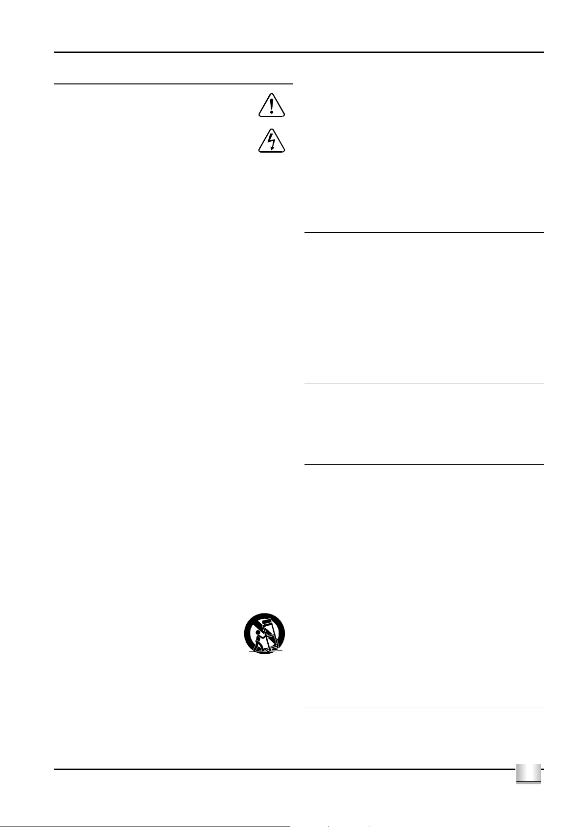
INSTALLATION (Refer to Fig 1):
Key to the rear panel drawing:
1. MC-Bus System Connection 9. Tuner Input
2. Pre-Amplifier Output 10. CD Input
3. Tape Recorder Output 11. PSX-R Connection
4. Tape Input 12. Headphone Output
5. MP3 Input 13. Power Inlet
6. Link Input 14. Mains Fuse Holder
7. Aux/PH Input 15. Power Switch
8. AV Input
Connecting to the AC Mains Supply
Connect the socket on the AC Power cable to the Power inlet 1# on the rear panel
of the Pre vs2. Now connect the cable to a suitable AC power point.
The mains power switch 1% on the rear panel of the Pre vs2 should be left on
for normal operation, except when left unattended for a long period when it
should be switched off or disconnected from the AC supply.
Connecting Tape/Disc recorders
To connect the tape recorder you will need two phono cables. Connect one
cable from the Output or Playback sockets of the tape deck to the TAPE Input
d of the Pre vs2 and a second cable from the Input or Record sockets of the
tape deck to the Tape Record Output - TP OUT c sockets of the Pre vs2.
Connecting Headphones
The headphones socket 1@ is a standard 6.35mm (¼") stereo jack socket for
connection to a pair of headphones. Headphones may be permanently
connected to the amplifier and selected when required with the front panel
switch.
MC-BUS System (Refer to figs 1 & 6)
Connecting the MC-BUS sockets a of the Pre vs2 in an MC-BUS system
provides unified system control. An MC-BUS loop is established by
connecting single phono cables from the MC-BUS output of one unit to the
MC-BUS input of another in a daisy-chain. Complete the loop by returning the
MC-BUS output of the final component to the MC-BUS input of the first.
With MC-BUS established you can control the power function of the entire
system from the Pre vs2, from the front panel or remote control. Selecting
'CD' from the front panel will switch on the Pre vs2, the Cyrus power amplifier
and a Cyrus CD player. When the Pre vs2 is set to Standby, the entire system
will also switch off.
When a Cyrus Surround Processor is in the MC-BUS loop, setting of the
volume calibration level will take place automatically when Pre vs2’s AV input
is selected. Refer to the handbook for the Surround Processor for further
details.
External Power Supply - PSX-R
The PSX-R is a unique DC power supply which will upgrade the sonic
performance of your Pre vs2. When a Pre vs2 / PSX-R combination is
installed, analogue and signal related sections of the Pre vs2 are powered
from this clean, stable power source while other requirements are supplied
internally. This ensures complete isolation of control circuits and sensitive
analogue sections reducing AC mains-borne noise and power supply ripple.
To connect the PSX-R to the Pre vs2 plug the connector on the umbilical cord
of the PSX-R into the Multi-Pole socket on the rear of the Pre vs2 (1! Fig.1)
You will need a mains supply for both units.
Connecting a Power Amplifier
Connect a phono cable from the Pre-amplifier Output sockets b to the input
of your power amplifier.
Connecting Signal Inputs
Connect a phono cable between each component and the sockets as marked
on the rear panel. Ensure left and right channels are correctly connected. The
Pre vs2 has inputs for CD Player - CD
decoder - AV h and three auxiliary inputs – AUX/PH g, LINK f and MP3 e
which can be used to connect a wide variety of products. Check the
specification of these products before connecting to your Pre vs2.
1), a tuner - TU i, a Home Theatre
Connecting a Turntable
The Pre vs2 is a line level amplifier. To play a turntable through your unit an
external phono pre-amplifier is required.
GB
GB
3
Page 5

Cyrus Pre vs2 User Instructions
OPERATION (Refer to fig 2)
Key to the front panel drawing:
1. Mute Switch
2. Standby Switch
3. Standby Light
4. Headphone Switch
5. Remote Eye
6. Level Control
7. TAPE Tape Monitor
8. MP3 Input
9. LINK Input
10. AUX/PH Input
11. Video (AV) Input
12. Tuner Input
13. CD Input
Power
When power is applied, the STANDBY key b is used for power control. The
Standby light c shows green when the Pre vs2 is operating and glows red
when in standby mode. The Pre vs2 will switch from standby to on, when any
input key h-1# is selected.
In regular use the Pre vs2 should be connected permanently to the mains
power supply. When left unattended for a long period (vacations etc) it should
be disconnected from the AC supply.
When the Pre vs2 is switched to Standby, all settings for input selection and
Volume/Balance are retained.
Selecting an Input
The INPUT SELECT keys h-1# switch selected input sources. When an input
key is selected, the red indicator above the key will turn on.
Tape/Disc Playback and Recording
Playback: You can play back a recording by selecting the appropriate key
TAPE g. When TAPE is selected the indicator above the selected key will
light in addition to the selected source. To cancel TAPE, press the TAPE key
again. If the tape recorder has a three-head facility, selecting the TAPE key
will monitor the recording directly from the third head, whilst recording.
Recording: To record, select an input to record with the relevant Key h-s
and follow the recording instructions in your tape deck manual.
Programmable Input Sensitivity (Refer to fig 4)
You may find an audible difference in level when switching from one input to
another due to the differing outputs of your source components. The unique
calibration memory of the Pre vs2 can be programmed to match the sensitivity
of all inputs with reference to the CD input. To program an offset:
1. Select CD input and set the volume control to a comfortable listening
level.
2. Select the desired input and hold the input key down. The volume
display switches to show input offset.
3. Adjust the level to the same audible volume as the CD player. The
display will read the offset applied.
4. Press the input key again to store this setting.
Repeat Steps 2 - 4 for each input to set the appropriate sensitivity level.
Fig. 4 shows settings for Input Sensitivity levels set -2 dB, 0dB and +2dB
relative to the CD input respectively.
Volume and Balance (Refer to fig 3)
The LEVEL CONTROL f of the Pre vs2 performs the dual functions of
volume and balance.
Volume: In normal mode the LEVEL CONTROL controls the volume in 1dB
steps. The light ring around the knob is calibrated to show the current
loudness level. When the volume is at minimum the first indicator on the light
ring will be RED. As the volume increases a GREEN light moves clockwise
around the ring. The volume setting is stored when the unit is set to standby.
Press the MODE control key on the remote control to change the
Balance:
mode of the front panel LEVEL CONTROL f to that of Left/Right Balance.
The light ring works in "reverse video" with the unlit section indicating the
position of L-R balance. You can alter L-R balance by up to +/-4dB or switch
one channel off when the control is turned to an extreme.
Mute
Pressing the MUTE Key a will fade the volume to minimum level without
disturbing the existing setting. When muted the RED minimum level indicator
will light as well as the existing GREEN light to show that the output is muted.
Move the volume knob up or press the Mute key to fade back up to the
original volume setting.
Listening to headphones
To listen to headphones, press the PHONES key d. The MUTE light at the
bottom of the light ring will now glow orange. The speakers will now be muted
for headphone listening. Press the PHONES key
loudspeaker operation.
NOTE: The PHONES key d only operates when headphones are connected
to the rear panel socket of the Pre vs2.
Caution: If you have been listening to headphones at high volume, be sure to
turn the level down before you switch to normal loudspeaker operation.
d again to restore
GB
4
GB
Page 6

User Instructions Cyrus Pre vs2
A
A
A
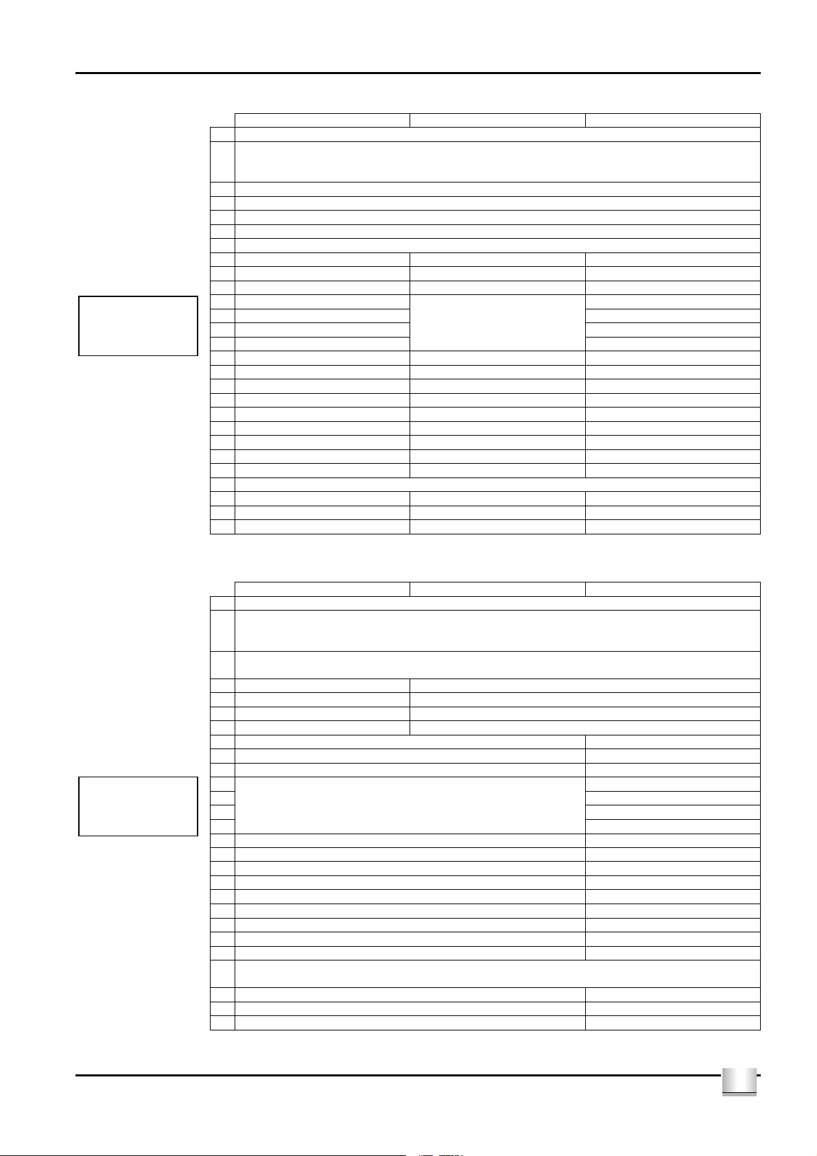
OPERATION WITH THE AVRS7.2 REMOTE CONTROL
The Pre vs2 is supplied with the Cyrus AVRS7.2 remote control which will
control Cyrus CD players, DVD players, tuners and surround sound decoders
in addition to the Pre vs2.
AVRS7.2 System select keys
System select keys
Commands may be sent to different Cyrus system components by selecting
the appropriate system select key on the handset. These keys are marked
CD, TU/DAB, AV, AV-S and SETUP. The CD, TU/DAB, AV, AV-S keys will
flash when any command is transmitted to show which type of product is
under control. Commands to a Surround Decoder from the SETUP system
will flash the AV-S indicator.
• Pressing CD will send commands to a Cyrus CD player. This key will
also switch on an amplifier and select the CD input.
• Pressing TU/DAB will send commands to DAB radios or FM Tuners.
This key will also switch on a DAB radio or FM Tuner and select the TU
input of an amplifier. To change between DAB or FM operation, hold
down the TU/DAB key for 3 seconds until the light changes colour. The
key will light green when set for DAB commands or red when set for FM
tuner commands. NOTE:- The FM band of a DAB radio is not selected
in this way, the BAND key is used for this purpose.
• Pressing AV will send commands to a DVD player. This key will also
switch on a DVD player and select the AV input of an amplifier.
The amplifier will respond to the volume, balance, mute and input keys when
any of the above systems are selected.
NOTE - The AV-S and SETUP keys are not used to control a stereo system.
b
d
h
i
1$
1%
1^
1*
1(
2)
2@
2$
2%
CD TU/DAB AV
MPLIFIER DVD
IN
ZOOM
NGLE
ADJ- ADJ+
DISP
12
456
789
SETUP
V
SETUP
OK
OFF
AV-S
a
c
e
f
NIGHT
g
DSP
1)
1!
1@
1#
1&
3
T-C
0
MENU
TREBLEBASS
LIPSYNC NOISEMODE
2!
2#
2^
2&
Multi-channel Surround Sound Systems
The AV-S and SETUP keys of the AVRS7.2 will control a Cyrus surround
decoder. If you own a Cyrus decoder which was not originally supplied with
an AVRS7.2 remote control, a full copy of the AVRS7.2 instruction sheet is
available on the Cyrus website www.cyrusaudio.com.
Full Remote Command Listing
A full listing of the command set available from the AVRS7.2 is listed in the
table opposite.
GB
GB
5
Page 7
Cyrus Pre vs2 User Instructions
CD MODE DAB MODE TU MODE (FM)
1 Power off all systems
CD, DAB, TU or AV COMMAND MODE SELECT
Amplifier, CD, DAB, FM tuner, DVD power on
Amplifier input select
Cursor keys for navigating the on-
screen menu options
Scan down
*early Cyrus CD players will respond to Play/Stop only
Amplifier, CD, DAB
and FM tuner
commands
2
3 AV SURROUND COMMAND MODE SELECT – see table overleaf
4 Stereo amp/preamp input select
5 Stereo amp/preamp balance select
6 Stereo amp/preamp volume control
7 Stereo amp/preamp mute
8 - Select station on display -
9 Audio phase invert - 10 Next/previous track Display next/previous station Next/previous preset
11 Next track Next preset
12 Search forward Scan up
13 Previous track Previous preset
14 Search reverse
15 - OK key to select menu options 16 Display off Display mode Display off
17 Play/pause/stop* Play/pause for replay from memory card 18 Display mode Timer record mode 19 Numeric keypad Numeric keypad Preset select
20 Memory store Preset information Preset store
21 - - 22 - - 23 - Menu select 24 AV SETUP MODE SELECT – see table below
25 - Record to memory card 26 - DAB/FM/Memory card band select 27 - Mono/stereo when playing FM Stereo/mono
Amplifier, DVD and
AV -Surround
commands
AV (DVD & amp) MODE AV-S (DVD & decoder) MODE AV-SETUP MODE
1 Power off all systems
2
3
4 Amplifier input select +/- Surround decoder input select +/-
5 Amplifier balance mode -
6 Amplifier volume control Surround decoder volume control
7 Amplifier mute Surround decoder mute
8 DVD Quick access zoom -
9 DVD Quick access angle 10 DVD Next/previous chapter/title Decoder Night & DSP functions
11 12 Adj +
13 14
15 OK key to select DVD menu options 16 DVD On-screen display 17 DVD transport functions 18 - 19 DVD Chapter/title direct access Speaker select keys
20 DVD Program store 21 DVD Title or Chapter mode 22 DVD Player setup Bass control select
23 DVD Disc menu Treble control select
24
25 - Mode select
26 - Lipsync adjust
27 - Decoder noise mode
Cursor keys for navigating the DVD on-screen menu options
CD, DAB, TU or AV COMMAND MODE SELECT
Amplifier, CD, DAB, FM tuner, DVD power on
Amplifier input select
AV-S COMMAND MODE SELECT
DVD and Surround decoder power on
Adj -
AV SETUP MODE SELECT
Surround decoder power on
GB
6
GB
Page 8
User Instructions Cyrus Pre vs2
TROUBLESHOOTING GUIDE
If your Pre vs2 is not operating properly, disconnect the power and check
carefully all connections.
If you are in any doubt, consult your dealer.
No sound
Pre vs2 in Standby Bring unit out of Standby
(Standby light - GREEN)
Power Amplifier switched off or in
Standby
Bring unit out of Standby
(Standby light - GREEN)
Mute is on (RED light on Vol. Ring) Deselect Mute
Tape Monitor on (RED tape light)
No sound from one loudspeaker
De-select Tape 2
BAL control at extreme limit Centralise Balance
Does your speaker have fuses? Check speaker, replace fuses
Speaker cables / interconnects faulty Check connections, cables -
replace if needed
Spurious noises from speakers
Interconnects or connections faulty Check, replace where necessary
No response from any keys
Switch off at rear panel, wait one minute and switch on.
The problem should clear
SPECIFICATIONS
WARRANTY
The warranty card enclosed should be completed by the Dealer and the
purchaser and returned to CYRUS or its Distributor within 8 days of
purchase. No Dealer or Distributor may vary the terms of this warranty,
which is personal to the original Purchaser and is not transferable.
Please retain the sales receipt as proof of purchase.
Warranty claims must wherever possible be made through the Dealer
from whom the equipment was purchased.
This warranty excludes:
• Damage caused through neglect, accident, misuse, wear and tear,
or through incorrect installation, adjustment or repair by
unauthorised personnel. Any unauthorised servicing will result in
loss of warranty.
• Liability for damage or loss occurring in transit to or from the
purchaser.
• Consequential damage, loss or injury, arising from or in conjunction
with this equipment.
Equipment for attention under warranty should be consigned return
carriage paid. If returned equipment is found to comply with the
published specification, CYRUS reserves the right to raise a charge.
The above conditions do not affect your statutory rights as a consumer.
Power Supply
Voltage:...........................................................................As plate on rear of unit
Power Consumption
Standby..........................................................................................................6W
ON..................................................................................................................9W
EMC & Safety Compliance (230V) ................................................................CE
EMC & Safety Compliance (115V) ...............................................FCC, cCSAus
Enclosure
Dimensions (WxHxD)............................................................ 215 x 75 x 365mm
Weight........................................................................................................3.7Kg
Material .....................................................................................Die cast chassis
Audio Performance
Input Sensitivity........................................................................................500mV
Input Impedance .......................................................................................40kΩ
Output Voltage ...........................................................................................0.94V
Max output voltage..........................................................................................9V
Output Impedance .......................................................................................50Ω
Frequency Response (-3dB)..................................................... 0.04Hz, 700kHz
Signal to Noise Ratio (unWTD).................................................................105dB
THD+N, 1kHz........................................................................................<0.003%
Cyrus reserves the right to change all specifications without notice. E &OE
GB
GB
7
Page 9

Cyrus Pre vs2 Gebrauchsanleitung
f
r
WICHTIGE HINWEISE! Unbedingt vor Benutzung des
Gerätes lesen!
VORSICHT:Das Ausrufungszeichen soll Ihre Aufmerksamkeit au
besonders wichtige Bedienungs- und Sicherheitshinweise in diese
Anleitung lenken.
ACHTUNG: Das Blitzzeichen weist Sie auf die Gefahr eines
elektrischen Schlages durch Bauteile im Innern des Gerätes hin.
Öffnen des Gerätes nur durch fachkundiges Personal.
Warnung: Um die Gefahr eines elektrischen Schlages zu vermeiden, dürfen die
Abdeckungen oder Gehäusewände dieses Geräts nicht entfernt werden. Das
Produkt enthält keine vom Benutzer zu wartenden Teile.
Warnung: Um die Gefahr eines elektrischen Schlages zu vermeiden, darf dieses
Gerät weder Regen noch Feuchtigkeit ausgesetzt werden.
BEACHTEN SIE DIE VORSICHTSHINWEISE: Alle Vorsichtshinweise am Produkt
und in der Gebrauchsanleitung müssen beachtet werden.
LESEN SIE ALLE ANLEITUNGEN: Alle Anweisungen zur Sicherheit und zum
Betrieb müssen vor der Benutzung des Gerätes gelesen werden.
BEWAHREN SIE DIE ANLEITUNGEN AUF: Die Anweisungen zur Sicherheit und
zum Betrieb müssen zum Nachlesen aufbewahrt werden.
BEFOLGEN SIE DIE ANWEISUNGEN: Alle Anweisungen zur Sicherheit und zum
Betrieb müssen befolgt werden.
REINIGUNG: Vor der Reinigung den Netzstecker ziehen. Keine flüssigen
Reinigungsmittel oder Sprays verwenden. Das Gerät mit einem angefeuchteten
Tuch reinigen.
WASSER UND FEUCHTIGKEIT: Verwenden Sie dieses Produkt nicht in der Nähe
von Wasser, z. B. Badewanne, Waschbecken, Spüle, Waschkübel, im feuchten
Keller oder in der Nähe eines Swimmingpools oder dergleichen. Das Gerät darf
niemals tropfenden oder spritzenden Flüssigkeiten ausgesetzt werden. Stellen sie
keinesfalls Vasen oder andere flüssigkeitsgefüllte Behälter auf das Gerät.
WÄRME: Das Produkt darf nicht in der Nähe von Wärmequellen wie
Heizungskörpern, Heizgeräten, Öfen oder von anderen wärmeerzeugenden
Produkten (einschließlich Verstärkern) aufgestellt werden.
LÜFTUNG: Die Schlitze und Öffnungen im Gehäuse dienen zur Belüftung, welche
den ausfallsicheren Betrieb des Produkts sicherstellt und es vor übermäßiger
Erwärmung schützt. Diese Öffnungen dürfen nicht blockiert oder verdeckt werden.
Aus dem Grund darf das Produkt nicht auf ein Bett, ein Sofa, einen Teppich oder
eine ähnliche weiche Oberfläche gestellt werden. Das Produkt eignet sich nicht für
den Einbau in ein Bücherregal oder ein Gestell, es sei denn, für eine ausreichende
Belüftung ist gesorgt und die Anweisungen des Herstellers werden eingehalten.
EINDRINGEN VON GEGENSTÄNDEN ODER FLÜSSIGKEITEN: Durch die
Öffnungen dürfen keinerlei Gegenstände in das Gerät eingeschoben werden, da
diese gefährliche Spannungspunkte berühren oder Teile kurzschließen könnten,
was einen Brand oder elektrischen Schlag verursachen kann.
ZUBEHÖR: Stellen Sie dieses Produkt nicht auf einen instabilen Rollwagen,
Ständer, Stativ oder Tisch oder bringen Sie es nicht an einer instabilen Halterung
an. Es kann herunterfallen, wobei Personen verletzt werden und Schäden am
Produkt entstehen können. Verwenden Sie nur Rollwagen, Ständer, Stative,
Halterungen oder Tische, die vom Hersteller empfohlen oder die mit dem Produkt
verkauft werden. Bei der Wandmontage des Produkts sind die Anweisungen des
Herstellers zu befolgen und das vom Hersteller empfohlene Zubehör ist zu
verwenden.
ZUSATZGERÄTE: Verwenden Sie keine Zusatzgeräte, die nicht vom Hersteller
empfohlen werden, da Gefahren entstehen können.
TRANSPORT: Wenn das Produkt auf einem Wagen transportiert
wird, ist Vorsicht geboten. Durch plötzliches Anhalten, übermäßige
Gewaltanwendung und unebenen Boden kann der Wagen mit dem
Produkt umstürzen.
NETZSPANNUNG: Dieses Produkt darf nur mit der auf dem Geräteschild
angegebenen Netzspannung betrieben werden. Wenn Sie nicht wissen, welche
Netzspannung bei Ihnen vorliegt, wenden Sie sich an Ihren Fachhändler oder Ihr
Elektrizitätswerk. Hinweise zu den Produkten, die mit Batterie oder anderen
Stromquellen betrieben werden, entnehmen Sie der Bedienungsanleitung.
ÜBERLAST: Wandsteckdosen, Verlängerungskabel oder integrierte Steckdosen
dürfen nicht überlastet werden, da dies die Gefahr eines Brandes oder elektrischen
Schlages verursachen kann.
NETZKABELSCHUTZ: Netzkabel müssen so verlegt werden, daß ein
Darüberlaufen oder Einklemmen durch Gegenstände verhindert wird. Besonders
ist auf die Abschnitte des Kabels in der Nähe eines Steckers, einer Steckdose
oder der Austrittsstelle aus dem Gerät zu achten.
OFFENE FLAMME: Keine offenen Flammenquellen wie z. B. Kerzen dürfen auf
das Gerät gestellt werden.
BLITZSCHUTZ: Bei Gewittern oder wenn das Produkt längere Zeit unbeaufsichtigt
oder unbenutzt bleibt, ziehen Sie als zusätzliche Schutzmaßnahme den
Netzstecker und trennen Sie die Antenne oder das Kabelsystem. Damit werden
Schäden durch Blitz oder Spannungsstöße verhindert.
VORISICHT! GEPOLTER STECKER (NUR IN DEN USA UND KANADA):
Zur Verhinderung eines elektrischen Schlages muß der flache Steckerstift in den
breiten Schlitz der Steckdose eingesteckt werden. Den Stecker ganz einstecken.
Wenn der Stecker nicht in Ihre Netzsteckdose paßt, dürfen Sie diesen nicht ändern
oder abtrennen. Lassen Sie von einem ausgebildeten Elektriker eine geeignete
Steckdose installieren.
NETZVERSORGUNG: (siehe Abbildungen 1)
Der eingekerbte IEC-Stecker des mitgelieferten Netzkabels gehört in den
entsprechenden Anschluß 1# auf der Rückseite des Geräts. Die Netzsicherung 1$
befindet sich ebenfalls auf der Rückseite neben dem Netzschalter. Sie darf
ausschließlich durch folgende Typen ersetzt werden:
Großbritannien / Europa ...................230V T800mAL/250V 20 mm
Nordamerika......................................115V T1.25AL/250V 20 mm
Die vorgeschriebene Betriebsspannung ist auf einem rückseitigen Aufkleber
angegeben. Stellen Sie vor dem Anschluß sicher, daß diese Ihrem örtlichen
Stromnetz entspricht, z. B.
230V Produkte: Spannungsbereich von 220V-240V
115V Produkte: Spannungsbereich von 110V-120V
Wenn Sie in eine andere Region mit unterschiedlicher Netzspannung umziehen,
wenden Sie sich an Ihren Cyrus Vertrieb, um die Anpassung des Geräts
vorzunehmen.
REPARATUREN:
Versuchen Sie nicht, dieses Produkt selbst zu reparieren oder die Verkleidungen
zu entfernen, da Sie sich dadurch Hochspannung oder anderen Gefahren
aussetzen würden. Überlassen Sie alle Reparaturen den Fachleuten.
BEDINGUNGEN, DIE REPARATUREN ERFORDERN: Ziehen Sie den
Netzstecker und beauftragen Sie den Kundendienst mit der Reparatur des
Gerätes, wenn:
• Netzkabel oder -stecker beschädigt sind
• Flüssigkeit oder Gegenstände in das Gerät eingedrungen sind
• das Gerät Regen oder Wasser ausgesetzt wurde
• das Gerät heruntergefallen oder anderweitig beschädigt ist
• das Gerät unter Befolgung der Bedienungsanleitung nicht normal
funktioniert. Verstellen Sie nur die Regler, die in der
Bedienungsanleitung beschrieben werden. Das unsachgemäße
Verstellen von anderen Reglern kann Schäden verursachen und
aufwendige Reparaturen durch einen qualifizierten Techniker erfordern,
um das Gerät wieder in seinen normalen Betriebszustand zu versetzen.
• das Produkt eine deutliche Leistungsminderung aufweist - in dem Fall ist
eine Reparatur notwendig.
ERSATZTEILE: Wenn Ersatzteile erforderlich sind, sollten Sie sich vergewissern,
daß der Techniker Ersatzteile verwendet, die vom Hersteller angegeben werden
oder die die gleichen Eigenschaften wie die Originalteile aufweisen. Unzulässige
Ersatzteile können Brände, elektrischen Schlag oder andere Gefahren
verursachen.
SICHERHEITSKONTROLLE: Bitten Sie den Techniker, im Anschluß an
Wartungs- oder Reparaturarbeiten Sicherheitskontrollen durchzuführen, um den
ordnungsgemäßen Betriebszustand des Gerätes zu bestätigen.
KUNDENDIENSTZENTRALEN:
Wenden Sie sich bei Fragen zum Produktservice oder bei technischen Problemen
nur an autorisierte Cyrus-Kundendienstzentralen. Eine Liste der Hauptzentralen
finden Sie auf der hinteren Umschlagseite dieser Bedienungsanleitung.
D
8
D
Page 10

Gebrauchsanleitung Cyrus Pre vs2
Willkommen in der Cyrus Welt!
Vielen Dank, daß Sie sich für Produkte aus der Cyrus-Serie entschieden
haben. Mit „state-of-the-art“ Konzeptionen und hervorragender
Produktqualität konnten wir weltweit zahllose Preise gewinnen. Wir sind
sicher, daß Ihnen dieses Gerät – von einem der anerkanntesten HiFiHersteller – immer viel Freude bereiten wird.
Lesen Sie bitte diese Anweisungen sorgfältig durch, bevor Sie mit der
Installation beginnen. So können Sie Ihren Pre vs2 sicher und korrekt in
Betrieb nehmen.
Vorbereitung der Installation
Bevor Sie Ihren Pre vs2 in Betrieb nehmen, überprüfen Sie bitte, ob sich die
folgenden Teile in der Accessory-Schachtel befinden:
• Garantiekarte (mit Bedienungsanleitung)
• Netzkabel
• Fernbedienung
• 2 x Cinch-Kabel für MC-BUS Verbindung
Bewahren Sie die Verpackung nach dem Auspacken auf.
Bauen Sie Ihren Pre vs2 an einem ausreichend belüfteten Platz auf – in
angemessener Entfernung von starken Wärmequellen, geschützt vor Staub
und Feuchtigkeit. Stellen Sie den Pre vs2 niemals unter ein anderes Gerät
oder auf irgendeine Oberfläche, die die Kühlung durch Verstopfen der
Ventilationsöffnungen behindern könnte.
INSTALLATION (siehe Abbildung 1)
Erklärung der Nummern auf der Rückseite des Pre vs2:
1. MC-BUS-System Anschluß 9. Tuner-Eingang
2. Vorverstärker-Ausgang 10. CD-Eingang
3. Tape-Ausgang 11. PSX-R-Anschluß
4. Tape-Eingang 12. Kopfhöreranschluß
5. MP3-Eingang 13. Netzeingang
6. Link-Eingang 14. Hauptsicherung
7. Aux/PH-Eingang 15. Netzschalter
8. AV-Eingang
Anschluß an die Netzversorgung
Stecken Sie die Buchse des mitgelieferten Netzkabels in den rückseitigen
Netzanschluß 1# des Pre vs2. Dann stecken Sie den Netzstecker in die
Steckdose.
Der Netzschalter 1% auf der Rückseite des Pre vs2 sollte normalerweise
eingeschaltet bleiben, es sei denn Sie nutzen das Gerät über längere Zeit
nicht. In diesem Fall sollten Sie ausschalten oder den Netzstecker ziehen.
Anschluß an einen Endverstärker
Verbinden Sie den Ausgang "PRE OUT" b über eine handelsübliche
Tonleitung (Cinch-Kabel) mit den Eingangsbuchsen Ihres Endverstärkers.
Anschluß der Signalquellen
Verbinden Sie die Cinch-Anschlußkabel Ihrer anderen Geräte mit den
Buchsen auf der Rückseite des Pre vs2, wie in der Zeichnung der
Anschlußbuchsen beschrieben. Achten Sie dabei immer darauf, daß die
Stecker für die jeweiligen Kanäle korrekt eingesteckt werden. Der Pre vs2
verfügt über Anschlußmöglichkeiten für einen CD-Spieler = CD 1), einen
Tuner = TU i, einen Heimkino-Decoder = AV h und drei ReserveEingängen = AUX/PH g, LINK f und MP3 e. Bitte überprüfen Sie die
technischen Daten dieser Geräte, bevor Sie diese an den Pre vs2
anschließen.
Anschluß eines Plattenspielers
Der Pre vs2 besitzt keinen Phono-Eingang. Zum Anschluß eines
Plattenspielers wird deshalb eine externe Phonostufe benötigt.
Anschluß von Tape/Disc Recordern
Zum Anschluß eines Taperecorders sind zwei Cinch-Kabel erforderlich.
Verbinden Sie ein Kabel von der Output oder Playback Buchse des
Recorders mit dem TAPE-Input d des Pre vs2 und das zweite Kabel von der
Input oder Record Buchse des Recorders mit den Aufnahme Ausgang – TP
OUT c Buchsen des Pre vs2.
Anschluß eines Kopfhörers
Die Kopfhörerbuchse 1@ ist eine Standard 6.35 mm Klinkenbuchse zum
Anschluß eines Stereokopfhörers. Der Kopfhörer kann permanent mit dem
Verstärker verbunden bleiben und über den Schalter auf der Gerätefront
aktiviert werden.
MC-Bus Systemverbindung (siehe Abbildungen 1 und 6)
Über die MC-Bus-Buchsen a können Sie Ihre verschiedenen CyrusKomponenten so miteinander verbinden, daß die Geräte zentral gesteuert
werden. Zum Aufbau einer MC-Bus-Kette verbinden Sie mit einzelnen CinchKabeln den MC-Bus-Ausgang der ersten mit dem MC-Bus Eingang der
nächsten Cyrus-Komponente, bis Sie am Eingang der ersten CyrusKomponente die Schleife vollenden.
Sind die Verbindungen hergestellt, können Sie an der Frontplatte des Pre vs2
oder über die Fernbedienung alle Komponenten ein- und ausschalten. Wenn
Sie den CD-Eingang des Pre vs2 wählen, dann schalten Sie damit den Pre
vs2, die Cyrus-Endstufe und den Cyrus CD-Spieler ein. Schalten Sie den Pre
vs2 in den Standby-Modus, dann schalten die anderen Komponenten
ebenfalls ab.
Wenn ein Cyrus surround Decoder in die MC-Bus-Verbindung eingeschleift
ist und der AV-Eingang gewählt wurde, dann erfolgt eine automatische
Lautstärke-Kalibrierung
Bedienungsanleitung des Cyrus surround Decoder nach.
. Weitere Details lesen Sie bitte in der
Externes geregeltes Netzteil PSX-R
Das PSX-R ist ein geregeltes externes Zusatznetzteil, das sowohl die
Klangqualität Ihres Pre vs2 als auch seine Stromabgabefähigkeit steigert.
Das PSX-R versorgt alle analogen und signalrelevanten Bereiche des Pre
vs2 mit reiner, äußerst stabiler Gleichspannung, während alle übrigen
Sektionen intern versorgt werden. Das isoliert die empfindlichen AnalogSektionen gegen Störimpulse aus der Steuerungselektronik und aus dem
Netz sowie verbleibende Brummspannung aus dem Netzteil.
Um das PSX-R mit dem Pre vs2 zu betreiben, stecken Sie das fest montierte
Kabel des PSX-R in die mehrpolige Buchse auf der Rückseite des Pre vs2
(1!, Abb. 1). Sie müssen beide Komponenten mit dem Netz verbinden.
D
D
9
Page 11

Cyrus Pre vs2 Gebrauchsanleitung
BEDIENUNG (siehe Abbildung 2)
Erklärung der Nummern auf der Frontplatte des Pre vs2
1. Mute-Taste 8. MP3-Taste
2. Standby-Taste 9. LINK-Taste
3. Standby-Leuchte 10. AUX/PH-Taste
4. PHONES - Kopfhörer - Taste 11. Video-AV-Taste
5. Infrarot-Empfänger 12. Tuner-Taste
6. Lautstärke-Regler 13. CD-Taste
7. TAPE-Tape Monitor-Taste
Einschalten (siehe Abbildung 2)
Wenn der Verstärker mit dem Netz verbunden ist, dient die Standby-Taste b
zum Ein- und Ausschalten. Die Standby-Leuchte c leuchtet rot, wenn der
Verstärker ausgeschaltet ist und grün, wenn er arbeitet. Der Pre vs2 schaltet
sich auch ein, wenn eine der Eingangsquellen Taste h–1# gewählt wird.
Der Netzschalter befindet sich auf der Rückseite. Dieser Schalter sollte
normalerweise immer eingeschaltet sein. Wenn das Gerät jedoch längere
Zeit nicht in Gebrauch ist, sollten Sie es abschalten oder vom Netz trennen.
Schalten Sie Ihr Gerät über die Standby-Taste aus, bleiben alle zuletzt
gewählten Einstellungen bis zum nächsten Gebrauch erhalten.
Eingangswahl
Mit den Eingangs-Tasten h–1# können Sie den gewünschten Eingang
wählen. Ein rotes Lämpchen über diesen Tasten signalisiert, welcher
Eingang gewählt wurde.
Tape/Disc Wiedergabe und Aufnahme
Wiedergabe: Durch betätigen der TAPE Taste g können Sie eine Aufnahme
abspielen. Zusätzlich zur angewählten Quelle leuchtet das Indikatorlämpchen
oberhalb der TAPE Taste, wenn diese gedrückt wurde. Durch erneutes
drücken der TAPE Taste wird dessen Funktion deaktiviert. Verfügt der
Taperecorder über ein Dreikopf-System, kann die Aufnahme nach betätigen
der TAPE Taste, während der Aufnahme über den dritten Tonkopf abgehört
werden.
Aufnahme: Um aufzunehmen, wählen Sie eine Signalquelle mittels der
entsprechenden Tasten h-1# und folgen den Anweisungen Ihrer
Taperecorder Gebrauchsanleitung.
Hören über Kopfhörer
Um den Kopfhörer zu aktivieren, drücken Sie die PHONES Taste d. Die
MUTE-Anzeige am unteren Ende des Lichtrings leuchtet jetzt orange und die
Lautsprecher werden ausgeblendet. Um die Lautsprecher wieder zu
aktivieren, drücken Sie nochmals die PHONES Taste
ANMERKUNG: Die PHONES Taste d reagiert nur wenn ein Kopfhörer mit
dem rückseitigen Anschluß des Pre vs2 verbunden ist.
Achtung: Sollten Sie im Kopfhörerbetrieb mit großer Lautstärke hören, stellen
Sie diese unbedingt vor dem Umschalten auf Lautsprecherbetrieb wieder auf
normalen Pegel.
d.
Programmierbare Eingangsempfindlichkeit
(siehe Abbildung 4)
Schalten Sie von einem Eingang zum nächsten, variiert die Lautstärke wegen
der unterschiedlichen Ausgangspegel der angeschlossenen Komponenten
immer ein wenig. Um diesen Effekt zu kompensieren, können Sie mit dem
Kalibrierungsspeicher des Pre vs2 alle Eingangsempfindlichkeiten bezogen
auf den CD-Eingang kompensieren. Um eine Anpassung der Eingänge
vorzunehmen, gehen Sie bitte wie folgt vor:
1. Wählen Sie den CD-Eingang und stellen den Drehregler auf
Zimmerlautstärke.
2. Wählen Sie den Eingang der justiert werden soll und halten Sie die
Taste gedrückt bis die Lautstärkeanzeige auf EmpfindlichkeitsKalibrierung umschaltet.
3. Gleichen Sie nun die Lautstärke des gewählten Eingangs an die
Lautstärke des CD-Spielers an. Sie können den Abgleich an der
Lautstärkeanzeige ablesen.
4. Speichern Sie die Kalibrierung indem Sie den schon vorher gewählten
Eingang erneut drücken.
Wiederholen Sie die Schritte 2-4, um weitere Eingänge zu justieren.
Abb. 5(a) - 5(c) zeigen Einstellungen für Eingangsempfindlichkeiten, die auf -
2 dB, 0 dB und + 2dB (ausgehend vom CD-Player) eingestellt wurden.
Lautstärke- und Balance-Einstellung (siehe Abbildung 3)
Der Drehknopf f am Pre vs2 dient sowohl der Lautstärke- als auch der
Balance-Einstellung.
Lautstärke: Im normalen Betrieb ändert der Drehregler f die Lautstärke in
1-dB-Schritten von minimaler bis maximaler Lautstärke. Der Leuchtring hinter
dem Drehknopf stellt eine kalibrierte Lautstärkeskala dar und verändert sich
proportional zum gewählten Pegel. Wenn der Regler auf Minimum steht,
leuchtet lediglich die erste Diode des Leuchtrings rot. Wenn das Gerät mit der
Standby-Taste abgeschaltet wurde, bleibt die zuletzt gewählte Lautstärke
gespeichert.
Balance: Drücken Sie die BALANCE Taste auf der Fernbedienung
Funktion des Lautstärke Einstellers auf der Gerätefront f auf Balance
umzustellen.
In dieser Betriebsart können Sie sowohl die Balance um bis zu +/- 4 dB nach
links oder rechts verschieben, als auch bei weiterem Drehen des Knopfs bis
zum äußeren Ende einen Kanal komplett abschalten. Der Balance-Modus
wird fünf Sekunden nach Loslassen des Drehknopfs automatisch verlassen.
Er kann auch vorher durch nochmaliges Drücken der Balance-Taste
abgeschaltet werden.
f um die
Muting
Die Betätigung der Mute-Taste a blendet die Lautstärke auf Minimal-Pegel,
ohne die bestehende Lautstärke-Einstellung zu verändern. Wurde die MuteTaste betätigt, leuchtet die rote Minimum-Anzeige der Lautstärke-Skala
zusätzlich auf. Durch leichtes Drehen des Lautstärke-Knopfs oder erneutes
Betätigen der Mute-Taste wird die Mute-Funktion aufgehoben und
automatisch die vorher gewählte Lautstärke wieder hergestellt.
10
D
D
Page 12

Gebrauchsanleitung Cyrus Pre vs2
A
A
A
BEDIENUNG DER FERNBEDIENUNG AVRS7.2
Zum Lieferumfang des Pre vs2 gehört die Fernbedienung Cyrus AVRS7.2, mit
der zusätzlich zum Verstärker, CD-Player, DVD-Player, Tuner und SurroundSound-Decoder gesteuert werden können.
Systemauswahltasten auf der AVRS7.2
Systemauswahltasten
Durch Auswahl der entsprechenden Systemauswahltaste auf dem Handset
können Befehle an verschiedene Cyrus Systemkomponenten gesendet werden.
Diese Tasten sind mit CD, TU/DAB, AV, AV-S und SETUP gekennzeichnet. Die
CD-, TU/DAB-, AV- und AV-S-Tasten blinken, wenn ein Befehl gesendet wird,
und geben hierdurch an, welche Komponente gerade gesteuert wird. Werden
Befehle vom SETUP-System an einen Surround-Decoder gesendet, blinkt die
AV-S-Anzeige.
• Wenn CD gedrückt wird, werden Befehle an einen Cyrus CD-Player
gesendet. Diese Taste dient auch zum Einschalten eines Verstärkers
und zur Auswahl des CD-Eingangs.
• Wenn TU/DAB gedrückt wird, werden Befehle an DAB-Radios oder
UKW-Tuner gesendet. Diese Taste dient auch zum Einschalten eines
DAB-Radios oder eines UKW-Tuners und zur Auswahl des TUEingangs eines Verstärkers. Wenn Sie zwischen DAB und UKW
umschalten möchten, halten Sie die TU/DAB-Taste 3 Sekunden lang
gedrückt, bis sich die Farbe der LED ändert. Die Taste leuchtet grün,
wenn sie für DAB-Befehle eingestellt ist, und rot, wenn sie für UKWTuner-Befehle eingestellt ist. HINWEIS: Das UKW-Band eines DABRadios wird nicht auf diese Weise ausgewählt; für diesen Zweck wird
die BAND-Taste verwendet.
• Wenn AV gedrückt wird, werden Befehle an einen DVD-Player
gesendet. Diese Taste dient auch zum Einschalten eines DVD-Players
und zur Auswahl des AV-Eingangs eines Verstärkers.
Der Verstärker reagiert auf die Volume-, Balance-, Mute- und Input-Tasten,
wenn eines der obigen Systeme ausgewählt wurde.
HINWEIS: Die AV-S- und SETUP-Tasten werden nicht zur Steuerung eines
Stereosystems verwendet.
b
d
h
i
1$
1%
1^
1*
1(
2)
2@
2$
2%
CD TU/DAB AV
MPLIFIER DVD
IN
ZOOM
NGLE
OK
ADJ- ADJ+
DISP
12
456
789
0
SETUP
V
LIPSYNC NOISEMODE
SETUP
MENU
TREBLEBASS
OFF
AV-S
a
c
e
f
NIGHT
g
DSP
1)
1!
1@
1#
1&
3
T-C
2!
2#
2^
2&
Mehrkanal-Surround-Sound-Systeme
Die AV-S- und SETUP-Tasten auf der AVRS7.2 steuern einen Cyrus
Surround-Decoder. Wenn Sie einen Cyrus Decoder besitzen, der
ursprünglich nicht mit einer Fernbedienung des Typs AVRS7.2 ausgeliefert
wurde, können Sie sich die vollständige Anleitung zur AVRS7.2 von der
Cyrus Website unter www.cyrusaudio.com herunterladen.
Überblick über alle auf der Fernbedienung zur
Verfügung stehenden Befehle
In der Tabelle auf der gegenüberliegenden Seite ist der vollständige auf der
AVRS7.2 zur Verfügung stehende Befehlssatz aufgeführt.
D
D
11
Page 13

Cyrus Pre vs2 Gebrauchsanleitung
CD-MODUS DAB-MODUS TU-MODUS (UKW)
1 Alle Systeme ausschalten
AUSWAHL DES BEFEHLSMODUS CD, DAB, TU oder AV
Verstärker, CD, DAB, UKW-Tuner, DVD einschalten
Auswahl des Verstärkereingangs
Cursortasten zum Durchlaufen der
Menüoptionen auf dem Bildschirm
Scan down (Suchlauf nach unten)
OK-Taste zur Auswahl von
Menüoptionen
Abspielen/Pause für Wiedergabe von
Memory-Karte
Auswahl des DAB/UKW/Memory-Karten-
Bands
*ältere Cyrus CD-Player reagieren nur auf „Abspielen/Stopp“
-
-
-
Befehle für
Verstärker, CD,
DAB und UKWTuner
2
3 AUSWAHL DES AV SURROUND-BEFEHLSMODUS – siehe Tabelle auf der nächsten Seite
4 Auswahl des Stereo-Verstärker-/Vorverstärker-Eingangs
5 Auswahl der Balance für Stereo-Verstärker/Vorverstärker
6 Auswahl der Lautstärke für Stereo-Verstärker/Vorverstärker
7 Stummschaltung (Mute) Stereo-Verstärker/Vorverstärker
8 - Auswahl des Senders auf dem Display -
9 Audiophase umkehren - 10 Nächster/vorheriger Titel/Track Nächsten/vorherigen Sender anzeigen Nächster/vorheriger Preset-Speicherplatz
11 Nächster Titel/Track Nächster Preset-Speicherplatz
12 Titelsprung vorwärts Scan up (Suchlauf nach oben)
13 Vorheriger Titel/Track Vorheriger Preset-Speicherplatz
14 Titelsprung rückwärts
15 16 Display aus Display-Modus Display aus
17 Abspielen/Pause/Stopp*
18 Display-Modus Timer-Aufnahmemodus -
19 Numerisches Tastenfeld Numerisches Tastenfeld Preset-Speicherplatz auswählen
20 Speicher Preset-Speicherplatz-Informationen Preset speichern
21 - - 22 - - 23 - Menüauswahl 24 AUSWAHL DES AV SETUP-MODUS – siehe Tabelle unten
25 - Aufnahme auf Memory-Karte -
26 27 - Mono/Stereo beim Hören von UKW Stereo/Mono
Befehle für
Verstärker, DVD
und AVSurround
AV (DVD & Verstärker) -MODUS AV-S (DVD & Decoder) -MODUS AV-SETUP-MODUS
1 Alle Systeme ausschalten
2
3
4 Auswahl des Verstärkereingangs +/- Auswahl des Eingangs für Surround-Decoder +/-
5 Balance-Modus Verstärker -
6 Lautstärkeregler Verstärker Lautstärkeregler Surround-Decoder
7 Stummschaltung (Mute) Verstärker Stummschaltung (Mute) Surround-Decoder
8 DVD Quick-Access-Zoom -
9 DVD Quick-Access-Winkel 10 DVD Nächstes/vorheriges Kapitel / Nächster/vorheriger Titel Nacht- & DSP-Funktionen für Decoder
11 12 Regler +
Cursortasten zum Durchlaufen der DVD-Menüoptionen auf dem Bildschirm
13 14
15 OK-Taste zur Auswahl von DVD-Menüoptionen 16 DVD-Display auf dem Bildschirm 17 DVD-Transportfunktionen 18 - 19 Direktzugriff auf DVD-Kapitel/Titel Lautsprecher-Auswahltasten
20 DVD-Programmspeicher 21 DVD-Titel- oder Kapitelmodus 22 DVD-Player-Einrichtung Bassregler
23 DVD Disc-Menü Höhenregler
24
25 - Modusauswahl
26 - Lipsync-Regler
27 - Decoder-Rauschmodus
AUSWAHL DES BEFEHLSMODUS CD, DAB, TU oder AV
Verstärker, CD, DAB, UKW-Tuner, DVD einschalten
Auswahl des Verstärkereingangs
AUSWAHL DES BEFEHLSMODUS AV-S
DVD und Surround-Decoder einschalten
Regler -
AUSWAHL DES AV SETUP-MODUS
Surround-Decoder einschalten
12
D
D
Page 14

Gebrauchsanleitung Cyrus Pre vs2
TECHNISCHE DATEN
Netzteil
Betriebsspannung:..........................................siehe Plakette auf der Rückseite
Leistungsaufnahme
Standby....................................................................................................... (6W)
AN ...............................................................................................................(9W)
EMC & Sicherheit konform mit (230V)........................................................... CE
EMC & Sicherheit konform mit (115V)...........................................FCC/cCSAus
Gehäuse
Abmessungen (BxHxT)......................................................... 215 x 75 x 365mm
Gewicht .....................................................................................................3.7 kg
Material ...................................................................................Druckgußchassis
Audio-Wiedergabe
Eingangsempfindlichkeit..........................................................................500mV
Eingangsimpedanz ...................................................................................40kΩ
Ausgangspegel ..........................................................................................0.94V
Frequenzgang (-3dB)................................................................ 0.04Hz, 700kHz
Geräuschspannungsabstand (A-bewertet)............................................ 105dBA
Klirrfaktor...............................................................................................<0.003%
Cyrus behält sich das Recht vor, alle technischen Spezfikationen ohne vorherige
Ankündigung zu ändern. E & OE.
GARANTIE
Die Garantie tritt nur in Kraft, wenn die beigefügte Garantiekarte vom Händler und
Käufer ausgefüllt und innerhalb von 8 Tagen nach dem Kauf an den CYRUS
Vertrieb zurückgeschickt wird. Keinem Händler oder Vertreiber ist es gestattet die
Bedingungen dieser Garantie zu verändern, die nur für den Erstbesitzer gilt.
Bitte bewahren Sie die Rechnung als Kaufnachweis auf.
Ansprüche müssen, wenn möglich, über den Händler geltend gemacht werden,
bei dem die Ware gekauft wurde.
Die Garantie beinhaltet nicht:
• Alle Schäden, die durch Unfall, falschen Gebrauch, Verschleiß oder durch
falsche Installation, Einstellung oder Reparatur durch unautorisiertes
Personal verursacht wurden. Alle nicht autorisierten Service-Eingriffe
haben den Garantieverlust zur Folge.
• Haftung für Beschädigung oder Verlust während des Transportes vom und
zum Käufer.
• CYRUS haftet nicht für eventuelle Sach- oder Personenschäden, die durch
den Gebrauch dieser Geräte oder in Verbindung mit diesen Geräten
entstanden sind.
Die Transportkosten (zum Händler und zurück) sind vom Käufer zu tragen.Stellt
sich bei der Überprüfung eines Gerätes heraus, daß es den angegebenen
technischen Spezifikationen entspricht, behält sich CYRUS das Recht vor,
Überprüfung und Rücktransport in Rechnung zu stellen.
Die hier angegebenen Bedingungen schränken Ihre Rechte als Käufer nicht ein
D
D
13
Page 15

Cyrus Pre vs2 Instrucciones de uso
IMPORTANTE! ¡LEASE ANTES DE HACER
FUNCIONAR ESTE EQUIPO!
PRECAUCIÓN: El signo de exclamación es para llamar su atención
sobre importantes instrucciones contenidas en este manual.
ATENCION: El símbolo del relámpago le avisa del riesgo de
descarga eléctrica que pueden presentar determinados componentes
en el interior de la unidad. No debe abrirse la unidad por personal no
autorizado.
AVISO: Para reducir el riesgo de una descarga eléctrica, no saque ninguna
cubierta o panel de la unidad. En este producto no hay piezas utilizables por
el usuario.
AVISO: Para reducir el riesgo de una descarga eléctrica, no exponga el
equipo a la lluvia o humedad.
OBSERVE LOS AVISOS: Se observarán todos los avisos de los productos y
de las instrucciones de funcionamiento.
LÉASE TODAS LAS INSTRUCCIONES: Se leerán todas las instrucciones
de seguridad y de funcionamiento antes de operar el producto.
GUARDE LAS INSTRUCCIONES: Se guardarán las instrucciones de
seguridad y de funcionamiento por si importa en el futuro.
SIGA LAS INSTRUCCIONES: Se seguirán todas las instrucciones de
funcionamiento y uso.
LIMPIEZA: Desenchufe este producto de la red de alimentación antes de
limpiar. No use limpiadores líquidos o de aerosol. Use un paño húmedo para
la limpieza.
AGUA Y HUMEDAD: No use este producto cerca del agua; por ejemplo,
cerca del baño, de una jofaina, de un fregadero de la cocina o del lavadero,
en un entresuelo húmedo; o cerca de una piscina o lugar parecido. El
producto no debe exponerse a goteos o salpicaduras, ni usarse como
soporte de objetos que contengan líquido (tiestos, jarrones...).
CALOR: El producto se colocará lejos de cualquier fuente de calor, como
radiadores, contadores térmicos, estufas u otros productos (incluyendo
amplificadores) que produzcan calor.
VENTILACIÓN: El aparato tiene ranuras y aberturas para la ventilación, a fin
de asegurar el funcionamiento correcto del producto y protegerlo contra el
recalentamiento. No se bloquearán o taparán estas aberturas, especialmente
colocando el producto en una cama, sofá, alfombra o superficie parecida.
Tampoco se colocará el producto en un montaje construido, como una
librería o estante a menos que se facilite la ventilación adecuada o se hayan
seguido las instrucciones del fabricante.
ENTRADA DE UN OBJETO O LÍQUIDO: Nunca introduzca un objeto de
cualquier tipo en este producto a través de las aberturas, pues podrían
tocarse puntos de tensión peligrosos o cortocircuitar ciertas piezas que
podrían causar un incendio o una descarga eléctrica.
ACCESORIOS: No coloque este producto en un carro, estand, trípode,
soporte, podría caerse el producto y ocasionar lesiones graves a un niño o a
un adulto y dañar considerablemente el producto. Use únicamente un carro,
estand, trípode, soporte o mesa recomendado por el fabricante o vendido con
el producto. Todo montaje del producto seguirá las instrucciones del
fabricante y para ello se usará un accesorio de montaje recomendado por el
fabricante.
FIJACIONES: No use fijaciones que no hayan sido recomendadas por el
fabricante del producto pues podría ocasionar peligros.
DESPLAZAMIENTO DEL PRODUCTO: Una combinación de
producto y carro se moverá con cuidado. Las paradas rápidas,
excesiva fuerza y superficies desiguales pueden originar el
vuelco de la combinación de producto y carro.
FUENTES DE ALIMENTACIÓN: Este producto se hará funcionar solamente
con el tipo de fuente de alimentación indicado en la etiqueta. Si no está
seguro del tipo de fuente de alimentación de su casa, consulte con el
concesionario del producto o compañía eléctrica local. Para aquellos
productos que se quieran operar desde una alimentación por batería, u otras
fuentes, refiérase a las instrucciones de funcionamiento.
SOBRECARGA: No sobrecargue los conectores murales, cables de
extensión o tomacorrientes integrales ya que puede resultar en un riesgo de
incendio o descarga eléctrica.
PROTECCIÓN DEL CORDÓN DE ALIMENTACIÓN: Los cordones de
alimentación se tenderán de manera que no puedan ser pisados o
pellizcados por artículos que se coloquen encima de ellos o contra ellos,
prestando especial atención a los cordones en las tomas, tomacorrientes y
puntos por donde salen del producto.
EXPOSICIÓN A LA LLAMA: Sobre este producto no deberán colocarse
objetos que generen llama directa (velas, etc.).
RELÁMPAGOS: Para mayor protección de este producto durante una
tormenta con relámpagos o cuando se deje desatendido o no se utilice
durante un período largo de tiempo, desenchúfelo del conector mural y
desconecte el sistema de la antena o cable. Esto evitará dañar el producto
debido a los relámpagos o sacudidas de la línea eléctrica.
¡PRECAUCIÓN! CONECTOR POLARIZADO (EE.UU. y CANADÁ
SOLAMENTE): Para evitar una descarga eléctrica, iguale la hoja del
enchufe a la ranura ancha, totalmente insertada. No altere o saque este
enchufe si no encaja en el enchufe de la alimentación de la red. Un
electricista competente debería instalarle un enchufe adecuado.
CONEXIÓN DE ALIMENTACIÓN (véase la figura 1)
El conector IEC moldeado del cable de red facilitado se conecta a la toma de
corriente 1# del panel posterior de la unidad. El fusible de red 1$ se
encuentra en el panel posterior, junto al interruptor de encendido. Sólo
deberá sustituirse de la siguiente manera:
Reino Unido/Europa .....................230V T800mAL/250V 20mm
Norteamérica ................................115V T1.25AL/250V 20mm
Los requisitos de alimentación de la fuente Pre vs2 se indican en una
etiqueta en el panel posterior. Antes de conectar, compruebe que la tensión
indicada coincide con su suministro de red, es decir:
Productos de 230V:.......................Margen de tensión 220-240V
Productos de 115V:.......................Margen de tensión 110-120V
Si se traslada a una zona con diferente tensión de red, consulte a su
distribuidor Cyrus para proceder a la conversión de la unidad.
MANTENIMENTO
No intente efectuar un servicio de este producto usted solo, pues al abrir o
sacar las cubiertas puede exponerse a tensiones peligrosas u otros peligros.
Deje todo trabajo de mantenimiento a personal especializado.
CONDICIONES QUE REQUIEREN MANTENIMIENTO: Desconecte el
producto del conector mural y deje el trabajo de mantenimiento a personal
especializado:
• Cuando el cordón de la fuente de alimentación o la toma estén
dañados.
• Si se ha vertido líquido, o han caído objetos en el producto.
• Si se ha expuesto el producto a la lluvia o agua.
• Si se ha dejado caer o se ha dañado el producto de alguna forma.
• Si el producto no funciona con normalidad al seguir las instrucciones
de funcionamiento. Ajuste únicamente los controles cubiertos por las
instrucciones de funcionamiento puesto que un ajuste inadecuado de
otros controles podría ocasionar daños y normalmente requerirá
amplio trabajo por parte de un técnico especializado para reponer el
producto a su funcionamiento normal.
• Cuando el producto tiene muestras claras de un cambio distintivo en
su rendimiento.
PIEZAS DE RECAMBIO: Cuando se necesiten piezas de recambio,
asegúrese de que el técnico de mantenimiento ha usado los recambios
especificados por el fabricante o tiene las mismas características que la pieza
original. Las sustituciones no autorizadas pueden resultar en un incendio,
descarga eléctrica u otros peligros.
COMPROBACIÓN DE SEGURIDAD: Al terminarse cualquier trabajo de
mantenimiento o reparación de este producto, pida al técnico de
mantenimiento que efectúe unas comprobaciones de seguridad a fin de
determinar que el producto está en condiciones adecuadas de
funcionamiento.
CENTROS DE MANTENIMIENTO DEL PRODUCTO
Para mantenimiento del servicio o asesoría técnica, contacte sólo centros de
mantenimiento Cyrus autorizados. Los centros principales se listan en la
cubierta posterior de este manual de instrucción.
14
E
E
Page 16

Instrucciones de uso Cyrus Pre vs2
Bienvenido al mundo Cyrus!
Le damos la enhorabuena por confiar en los aparatos Hi-fi Cyrus. Nuestra
tecnología de diseńo de vanguardia y nuestra alta calidad de fabricacion nos
han asegurado incontables premios en todo mundo.
Confiamos que Vd. Disfrute igualmente de un producto fabricado por uno de
los más respetados fabricantes de Hi-fi.
Por favor lea estas intrucciones con cuidado antes de comenzar la
instalación.
Son su mejor guía para instalar el Pre vs2 correctamente.
Preparación
Antes de instalar el Pre vs2, compruebe que la caja de accesorios contiene los
siguientes elementos:
• Tarjeta de garantía (con el manual de instrucciones)
• Cable de alimentación
• Mando a distancia
• 2 cables MC-Bus
Una vez extraídos de la caja, conserve el embalaje.
Instale el Pre vs2 en un lugar debidamente ventilado, lejos de fuentes de calor,
polvo o humedad. No sitúe nunca el Pre vs2 debajo de otro equipo ni encima de
superficies en las que se pueda obstaculizar la ventilación.
INSTALACIÓN (véase la figura 1)
Identificación de los números del panel posterior del amplificador Pre vs2:
1. Conexión del sistema MC-BUS 9. Entrada sintonizador
2. Salida preamplificador 10. Entrada CD
3. Salida grabadora de cinta 11. Conexión PSX-R
4. Entrada de cinta 12. Toma de auriculares
5. Entrada MP3 13. Toma de corriente
6. Entrada LINK 14. Fusible de red
7. Entrada AUX/PH 15. Interruptor de encendido
8. Entrada AV
Conexión de alimentación
El conector IEC moldeado del cable de red facilitado se conecta a la toma de
corriente 1# del panel posterior de la unidad.
El interruptor de encendido 1% está situado en el panel posterior del Pre vs2
(véase la figura 1, ilustración del panel posterior). Este interruptor deberá
dejarse normalmente activado, a no ser que la unidad vaya a permanecer
inactiva durante un período prolongado. En tal caso, deberá apagarse el
interruptor o desconectarse la unidad del suministro de c.a.
Conectando Auriculares
El conector de auriculares es ún conector estéro estándard 6,35mm (¼”) para
la conexión de un par de auriculares. Los auriculares pueden estar
permanentemente conectados al amplificador y seleccionarse cuando se
precise con el conmutador del panel frontal.
Conexión de sistema MC-Bus
(Véanse las figuras 1 a 6)
La conexión de los terminales MC-Bus b del Pre vs2 a un sistema MC-Bus
proporciona el control unificado del sistema. Conectando en cadena unos cables
de audio sencillos entre la salida MC-Bus de una unidad y la entrada MC-Bus de
la siguiente, se establecerá un bucle MC-Bus. Complete el bucle conectando la
salida MC-Bus del último componente a la entrada MC-Bus del primero.
Con la conexión MC-BUS establecida, puede controlar el encendido de todo el
sistema desde el Pre vs2, tanto desde el panel frontal como desde el mando a
distancia. Si selecciona "CD" en el panel frontal, se encenderán el Pre vs2, un
amplificador de potencia Cyrus y un reproductor de CD Cyrus. Cuando el Pre vs2
entre en espera, también lo hará la totalidad del sistema.
Si en el bucle MC-BUS hay insertada una unidad Cyrus AV8 o AV5, el ajuste del
nivel de calibración del volumen se producirá de forma automática en cuanto se
seleccione la entrada VI del Pre vs2. Para más detalles, consulte el manual del
procesador Surround Cyrus .
Fuente de alimentación regulable Cyrus PSX-R
La unidad PSX-R es una exclusiva fuente de alimentación de c.c. que mejorará
las prestaciones acústicas del Pre vs2 y su gestión de corriente. Con una
combinación Pre vs2/PSX-R instalada, las secciones analógicas y las
relacionadas con señales del Pre vs2 se alimentan de esta fuente nítida y estable,
mientras el resto de requisitos se suministran a nivel interno. De esta forma se
garantiza un completo aislamiento de los circuitos de control y las sensibles
secciones analógicas, reduciendo el ruido generado en la red y las ondulaciones
del suministro.
Para conectar la fuente de alimentación PSX-R al Pre vs2, acople el conector del
cable umbilical de la PSX-R a la toma multipolar de la parte posterior del Pre vs2
[1!, fig. 1]. Ambas unidades necesitarán suministro de red.
Conexión de las entradas de señal
Conecte un cable de audio entre cada uno de los componentes y las
entradas correspondientes del panel posterior. Procure conectar
debidamente los canales derecho e izquierdo. El Pre vs2 dispone de
entradas para reproductor de CD [CD 1)], sintonizador [TU i],
descodificador de cine en casa [AV h] y tres auxiliares [AUX/PH g, LINK f
y MP3 e], que pueden utilizarse para conectar una gran variedad de
productos. Compruebe las especificaciones técnicas de estos productos
antes de conectarlos al Pre vs2.
Conectando un Giradiscos
El Pre vs2 es un amplificador de nivel de línea. Para poder conectar un
giradiscos se precisa un pre-amplificador externo de fono.
Conectando grabadoras de Cinta/Disco
Para conectar la grabadora de cinta se necesitan dos cables fono. Conecte
un cable desde la salida o conectores de reproducción de la cassette a la
correspondiente entrada de cinta – TAPE del Pre vs2 y un segundo cable
desde la entrada o conectores de grabación de la cassette a la salida de
grabación – TP OUT del Pre vs2.
E
E
15
Page 17

Cyrus Pre vs2 Instrucciones de uso
FUNCIONAMIENTO (véase la figura 2)
Identificación de los números del panel frontal del amplificador Pre vs2:
1. Interruptor de silenciamiento 8. MP3 - Entrada
2. Interruptor de espera 9. LINK - Entrada
3. Indicador de espera 10. AUX/PH - Entrada
4. PHONES - Auriculares 11. Entrada de vídeo (AV)
5. Sensor remoto 12. Entrada de sintonizador
6. Control de nivel 13. Entrada de CD
7. TAPE - Monitor de Cinta
Encendido (Ahora consulte la figura 2, ilustración del panel frontal)
En un uso normal del Pre vs2, con suministro permanente de corriente, el
botón de espera b puede emplearse para encender y apagar la unidad. El
indicador de espera lucirá de color rojo cuando el Pre vs2 se encuentre en
posición de espera, y de color verde cuando esté en funcionamiento.
En el uso habitual, el Pre vs2 debería conectarse permanentemente al
suministro de energía de red. Cuando no se vaya a hacer funcionar durante
un largo período de tiempo (vacaciones, etc.) debería desconectarse del
suministro de c.a.
En el modo de espera se conservan todos los ajustes de selección de entrada y
de volumen y balance.
Selección de una entrada
Los botones INPUT SELECT h-1# seleccionan las distintas fuentes de entrada.
Cuando se selecciona una entrada, se ilumina el indicador rojo situado encima del
botón.
Reproducción y Grabación Cinta/Disco
Reproducción: Puede reproducirse una grabación seleccionando TAPE.
Cuando se selecciona TAPE, el indicador situado encima de la tecla
seleccionada. Para cancelar TAPE, pulse TAPE otra vez.
Grabación: Seleccione una entrada para grabar con el botón
correspondiente y siguiendo las instrucciones de grabación del manual de su
cassette.
Escucha con auriculares
Para la escucha con auriculares, pulse el botón PHONES. La luz MUTE
situada en la parte inferior de la banda luminosa se vuelve naranja. Los
altavoces se enmudecen y se escucha con auriculares. Pulse el botón
PHONES de nuevo para restaurar el functionamiento de los altavoces.
Nota: El botón PHONES opera solamente cuando los auriculares están
conectados al conector del panel trasero del Pre vs2.
Aviso: Si ha estado escuchando con auriculares a alto volumen, asegúrese
de bajarlo antes de pasar a la escucha con altavoces.
Sensibilidad de entrada programable
(Véase la figura 4 de la hoja desplegable)
Quizás perciba una acusada variación de nivel cuando cambie de una entrada a
otra, debido a la diferencia de salida de los componentes fuente. La exclusiva
memoria de calibración del Pre vs2 puede programarse en función de la
sensibilidad de las entradas con respecto a la de CD. Para programar una
compensación:
1. Seleccione la entrada de CD y ajuste el control de volumen a un nivel
confortable.
2. Seleccione la entrada deseada y mantenga pulsado su botón. La lectura de
volumen pasará a reflejar el ajuste de compensación de entrada.
3. Ajuste el nivel al mismo volumen audible que el reproductor de CD. La
pantalla indicará la compensación aplicada.
4. Pulse de nuevo el botón de entrada para memorizar este ajuste.
Repita los pasos 2 a 4 con cada entrada para ajustar el nivel de sensibilidad
adecuado.
Las figuras 5(a)-5(c) muestran respectivamente los ajustes para unos niveles de
sensibilidad de entrada de -2 dB, 0 dB y +2 dB con respecto a la entrada de CD.
Control de volumen y balance
(Véase la figura 3 de la hoja desplegable)
El control de nivel LEVEL CONTROL f del Pre vs2 ajusta tanto el volumen como
el balance.
Volumen: En el modo normal, el control de nivel regula el volumen en pasos de
1 dB. El anillo luminoso que rodea el mando está calibrado para indicar el nivel
acústico de cada momento. Cuando el volumen se encuentra en la posición
mínima, el primer indicador del anillo luminoso aparecerá en rojo. Según se vaya
elevando el volumen, una luz verde se irá desplazando alrededor del anillo. El
ajuste de volumen se conserva siempre cuando la unidad entra en el modo de
espera.
Pulse el botón de control de Balance del mando a distancia para
Balance:
cambiar el modo de control de nivel del panel frontal a balance
izquierda/derecha. El anillo luminoso funciona en "vídeo invertido", es decir, la
sección apagada indica la posición del balance derecha/izquierda. Puede alterar
el balance en un máximo de ±4 dB, así como desactivar por completo un canal
llevando el control hasta el extremo. El mando restablecerá el control del volumen
tras 5 segundos de inactividad.
Silenciamiento
Pulsando el botón MUTE a se reducirá el volumen al mínimo sin alterar el ajuste
existente. Cuando está silenciada la unidad, el indicador de nivel mínimo de color
rojo permanece encendido, al igual que la luz verde que haya iluminada,
indicando que la salida está interrumpida. Mueva el mando de volumen o pulse el
botón de silenciamiento para restablecer el nivel de volumen original.
16
E
E
Page 18

Instrucciones de uso Cyrus Pre vs2
A
A
A
FUNCIONAMIENTO CON EL MANDO A DISTANCIA
AVRS7.2
El Pre vs2 se suministra con el mando a distancia Cyrus AVRS7.2 que
controlará los reproductores de CD, reproductores de DVD, sintonizadores y
descodificadores de sonido surround Cyrus además del Pre vs2.
Teclas de selección de sistema AVRS7.2
Teclas de selección de sistema
Pueden enviarse instrucciones a diferentes componentes del sistema Cyrus
seleccionando la tecla de selección de sistema apropiada en el mando. Estas
teclas están marcadas como CD, TU/DAB, AV, AV-S y SETUP. Las teclas
CD, TU/DAB, AV, AV-S se iluminarán de forma intermitente cuando se
transmita cualquier instrucción para indicar qué tipo de producto se está
controlando. Las instrucciones hacia un descodificador de Surround desde el
sistema SETUP harán que el indicador AV-S se encienda de forma
intermitente.
• Al pulsar CD se enviarán instrucciones a un reproductor de CD Cyrus.
Esta tecla también conectará un amplificador y seleccionará la entrada
CD.
• Al pulsar TU/DAB se enviarán instrucciones a los aparatos de radio
DAB o Sintonizadores de FM. Esta tecla también conectará un aparato
de radio DAB o Sintonizador de FM y seleccionará la entrada TU de un
amplificador. Para cambiar entre funcionamiento DAB o FM, mantenga
pulsada la tecla TU/DAB durante 3 segundos hasta que la luz cambie
de color. La tecla se iluminará en color verde cuando esté ajustada
para instrucciones de DAB o rojo cuando esté ajustada para
instrucciones de sintonizador de FM. NOTA:- La banda de FM de un
aparato de radio DAB no se selecciona de esta forma; para ello se
usan la tecla BAND.
• Al pulsar AV se enviarán instrucciones a un reproductor de DVD. Esta
tecla también conectará un reproductor de DVD y seleccionará la
entrada AV de un amplificador.
El amplificador responderá a las teclas de entrada de volumen, equilibrio,
reducción de volumen al mínimo y entrada cuando se seleccione cualquiera
de los sistemas anteriores.
NOTA – Las teclas AV-S y SETUP no se utilizan para controlar un sistema
estéreo.
b
d
h
i
1$
1%
1^
1*
1(
2)
2@
2$
2%
CD TU/DAB AV
MPLIFIER DVD
IN
ZOOM
NGLE
ADJ- ADJ+
DISP
12
456
789
SETUP
V
SETUP
OK
OFF
AV-S
a
c
e
f
NIGHT
g
DSP
1)
1!
1@
1#
1&
3
T-C
0
MENU
TREBLEBASS
LIPSYNC NOISEMODE
2!
2#
2^
2&
Sistemas de Sonido Surround Multicanal
Las teclas AV-S y SETUP del AVRS7.2 controlarán un descodificador de
surround Cyrus. Si tiene un descodificador Cyrus que no se suministrara
originalmente con un mando a distancia AVRS7.2, se dispone de una copia
completa de la hoja de instrucciones del AVRS7.2 en el sitio web de Cyrus,
www.cyrusaudio.com.
Listado Completo de Instrucciones del Mando a
Distancia
En la tabla siguiente se obtiene un listado completo del conjunto de
instrucciones disponibles del AVRS7.2.
E
E
17
Page 19

Cyrus Pre vs2 Instrucciones de uso
MODO CD MODO DAB MODO SINTONIZADOR (FM)
1 Apagado de todos los sistemas
2
3 SELECCIÓN DE MODO DE INSTRUCCIONES DE AV SURROUND – ver la tabla al dorso
4 Selección de entrada de amp / preamp estéreo
5 Selección de equilibrio de amp / preamp estéreo
6 Control de volumen de amp / preamp estéreo
7 Reducción de volumen al mínimo de amp / preamp estéreo
8 - Selección de emisora en la pantalla -
9 Inversión de fase de audio - 10 Pista siguiente / anterior Visualizar la emisora siguiente / anterior Preajuste siguiente / anterior
11 Pista siguiente Preajuste siguiente
12 Búsqueda hacia delante Búsqueda hacia delante
13 Pista anterior Preajuste anterior
14 Búsqueda hacia atrás
15 - Tecla OK para seleccionar las opciones de menú 16 Apagado de la pantalla Modo de visualización Apagado de la pantalla
Instrucciones de amplificador, CD,
17 Reproducción / pausa / parada *
DAB y sintonizador de FM
18 Modo de visualización Modo de registro de reloj 19 Teclado numérico Teclado numérico Selección de preajuste
20 Almacenamiento en memoria Información de preajuste Almacenamiento de preajuste
21 - - 22 - - 23 - Selección de menú 24 SELECCIÓN DE MODO DE AJUSTE DE AV – ver la tabla siguiente
25 - Registro en la tarjeta de memoria 26 27 - Mono / estéreo al reproducir FM Estéreo / mono
SELECCIÓN DE MODO DE INSTRUCCIONES DE CD, DAB, TU o AV
Teclas de cursor para navegar en las opciones de
menú de la pantalla
Búsqueda hacia atrás
Reproducción / pausa para reproducción desde la
Selección de banda de la tarjeta de DAB / FM /
* los reproductores de CD Cyrus anteriores sólo responderán a Reproducción / parada
-
-
MODO AV (DVD y amp) MODO AV-S (DVD y descodificador) MODE DE AJUSTE DE AV
1
2
3
4
Selección de entrada de amplificador +/- Selección de entrada de descodificador de surround +/-
5
Modo de equilibrio de amplificador -
6
Control de volumen de amplificador Control de volumen de descodificador de surround
Reducción de volumen al mínimo de
7
8
9
10
11
12
Teclas de cursor para navegar en las opciones de menú en pantalla de DVD
13
14
15
16
17
Instrucciones de Amplificador, DVD y
18
AV - Surround commands
19
20
21
22
23
24
25
26
27
Tecla OK para seleccionar las opciones de menú de DVD -
Zoom de acceso rápido de DVD -
Ángulo de acceso rápido de DVD -
Capítulo / título siguiente / anterior de DVD Funciones DSP y nocturna de descodificador
Visualización en pantalla de DVD -
Funciones de transporte de DVD -
Acceso directo a capítulo / título de DVD Teclas de selección de altavoces
Almacenamiento de programas de DVD -
Modo de título o capítulo de DVD -
Ajuste de reproductor de DVD Selección de control de bajos
Apagado de todos los sistemas
SELECCIÓN DE MODO DE INSTRUCCIONES DE CD, DAB, TU o AV
SELECCIÓN DE MODO DE INSTRUCCIONES DE AV-S
Reducción de volumen al mínimo de descodificador de surround
-
Aj +
-
Aj -
--
Menú de disco de DVD Selección de control de agudos
SELECCIÓN DE MODO DE AJUSTE DE AV
- Selección de modo
-
- Modo de ruido de descodificador
Ajuste de sincronización del sonido con las
18
E
E
Page 20

Instrucciones de uso Cyrus Pre vs2
SOLUCIÓN DE PROBLEMAS
Si advierte que el Pre vs2 no funciona correctamente, desconecte la alimentación
y revise detenidamente todas las conexiones observando las indicaciones del
manual. Si el problema persiste, quizás le sirvan de ayuda los siguientes puntos.
En caso de duda, póngase en contacto con su distribuidor.
No hay sonido
Amplificador apagado o en espera Desactive el modo de espera (luz
Silenciamiento activado (luz roja
en el anillo del mando de volumen)
Monitorización de cinta activado
(luz de sección de cinta de color rojo)
No hay sonido en un altavoz
Balance ajustado en un extremo Centre el balance
¿Tiene fusibles el altavoz? Revise el altavoz, sustituya los fusibles
Error en cables/conexiones de altavoz Revise los cables y conexiones.
Ruidos parásitos en altavoces
Cables o conexiones defectuosas Revisar y sustituir si es preciso
No responde ningún botón
Apague la unidad del panel posterior, espere un minuto y enciéndala de nuevo. El
problema deberá quedar resuelto.
verde)
Desactive el silenciamiento
Accione la fuente
Sustituir si es necesario
ESPECIFICACIONES
Alimentación
Tensión: ..................................................................Véase placa en panel posterior
Consumo
Espera....................................................................................................................6W
Encendido..............................................................................................................9W
EMC & Requisitos de seguridad (230V).................................................... CE
EMC & Requisitos de seguridad (115V)....................................FCC/cCSAus
Carcasa
Dimensiones (anch. x alt. x prof.)..............................................215 x 75 x 365 mm
Peso .................................................................................................................. 3.7Kg
Material...........................................................................................Chasis moldeado
GARANTÍA
La tarjeta de garantía adjunta deberá ser cumplimentada por el Vendedor y el
Comprador, y remitida a CYRUS o a su Distribuidor antes de 8 días a partir de la
fecha de compra. Ningún Vendedor ni Distribuidor podrá variar las condiciones de
la presente garantía, considerada personal e intransferible para el comprador
original.
Conserve la factura de compra como justificante.
Las reclamaciones al amparo de la presente garantía habrán de realizarse
siempre que sea posible a través del Vendedor a quien se adquirió el equipo.
Esta garantía no cubre:
• Los daños ocasionados por negligencia, accidente, uso indebido o
desgaste, así como por la instalación, ajuste o reparación incorrectos por
personal no autorizado. La prestación de un servicio sin autorización
supondrá la anulación de la garantía.
• Responsabilidad por pérdida o daños ocasionados durante el transporte
hasta o desde el domicilio del comprador.
• Pérdidas o daños materiales o personales derivados del uso directo o
indirecto del equipo.
El equipo atendido al amparo de la presente garantía deberá ser consignado a
portes pagados. Si el equipo resulta cumplir las especificaciones publicadas,
CYRUS se reserva el derecho a reclamar los gastos pertinentes.
Las anteriores condiciones no afectan a sus derechos estatutarios como cliente.
Características de audio
Sensibilidad de entrada ...........................................................................500mV
Impedancia de entrada......................................................................... 40kOhm
Nivel de salida.....................................................................................0.94V rms
Impedancia de salida ................................................................................. 50Ω
Respuesta en Frecuencia (-3 dB)............................................. 0.04Hz, 700kHz
Relación S/R (A-WTD)........................................................................... 105dBA
THD+ruido 1kHz ...................................................................................<0,003%
Cyrus reserva el derecho de cambiar las eespecificaciones sin previo aviso. E & OE
E
E
19
Page 21

Cyrus Pre vs2 Manuel d’utilisation
r
personne
autorisé ne doit pas ou
cet appare
IMPORTANT ! A lire avant l’utilisation de l’appareil !
MISE EN GARDE : Le point d’exclamation est là pour attire
votre attention sur les instructions importantes et les
procédures de sécurité de ce manuel.
ATTENTION : L’éclair vous avertie des risques de chocs
électriques présentés par les composants internes. Le
l non
AVERTISSEMENT : Pour éviter tout risque d’électrocution ne retirez aucun
couvercle ni panneau de l’appareil. Ce produit ne comporte aucune pièce
réparable par l’utilisateur.
AVERTISSEMENT: Pour éviter tout risque d’électrocution, n’exposez pas cet
équipement à la pluie ni à l’humidité.
TENEZ COMPTE DES AVERTISSEMENTS : Tous les avertissements sur le
produit et dans le mode d’emploi doivent être observés.
LISEZ TOUTES LES INSTRUCTIONS : Toutes les instructions de sécurité et
de fonctionnement doivent être lues avant d’utiliser le produit.
CONSERVEZ LES INSTRUCTIONS : Les instructions de sécurité et de
fonctionnement doivent être gardées pour référence ultérieure.
SUIVEZ LES INSTRUCTIONS : Toutes les instructions de sécurité et de
fonctionnement doivent être observées.
NETTOYAGE: Débranchez l’appareil du secteur avant le nettoyage. N’utilisez
pas de produits de nettoyage liquides ou en aérosol. Utilisez un chiffon
humide pour le nettoyage.
EAU ET HUMIDITÉ : N’utilisez pas ce produit près de l’eau – par exemple,
près d’une baignoire, d’un lavabo, d’un évier, dans un sous-sol humide, près
d’une piscine ou d’un lieu similaire. L’appareil ne doit pas être exposé à des
projections d’eau et aucun objet contenant un liquide, tel un vase, ne doit être
placé sur l’appareil.
CHALEUR : Le produit doit être éloigné de toute source de chaleur telle que
des radiateurs, des cuisinières, ou tout autre produit (dont les amplificateurs)
qui génèrent de la chaleur.
VENTILATION : Les fentes et les ouvertures sur le châssis sont prévues pour
la ventilation, pour assurer le fonctionnement fiable du produit et pour le
protéger contre toute surchauffe; et ces ouvertures ne doivent pas être
obturées ni couvertes. Les ouvertures ne doivent jamais être bloquées en
plaçant le produit sur un lit, un sofa, un tapis ou une surface similaire. Ce
produit ne doit pas être placé dans une installation encastrée comme une
bibliothèque à moins qu’une ventilation adéquate ne soit assurée ou que les
instructions du fabricant aient été observées.
INSERTION D’OBJETS OU DE LIQUIDE : N’insérez jamais d’objets
d’aucune sorte à l’intérieur de l’appareil à travers les ouvertures car ceux-ci
pourraient toucher des points de tension dangereux ou de court-circuiter des
pièces, d’où un risque d’incendie ou d’électrocution.
ACCESSOIRES : Ne placez pas ce produit sur un meuble, un socle, un
trépied, un support ou une table instable. L’appareil risque de tomber et de
causer des blessures graves à un enfant ou un adulte, et de causer un
endommagement important du produit. Utilisez uniquement un meuble, un
socle, un trépied, un support ou une table recommandée par le fabricant, ou
vendus avec le produit. L’installation de l’appareil doit être conforme aux
instructions du fabricant et doit être effectuée avec un accessoire de montage
recommandé par le fabricant.
FIXATIONS : N’utilisez pas de fixations non recommandées par le fabricant
du produit car leur utilisation représente un risque.
DÉPLACEMENT : Le produit sur un meuble à roulettes doit
être déplacé avec précaution. Des arrêts soudains, une force
excessive et des surfaces irrégulières représentent un risque
de basculement pour le produit et le meuble à roulettes.
SOURCE D’ALIMENTATION : Ce produit doit être utilisé uniquement à partir
du type de source d’alimentation indiqué sur l’étiquette de marquage. Si vous
n’êtes pas sûr(e) du type d’alimentation que vous avez, consultez votre
revendeur ou votre compagnie d’électricité. Pour les produits destinés à
fonctionner sur piles, ou d’autres sources, consultez le mode d’emploi.
SURCHARGE : Ne surchargez pas les prises murales, les cordons
d’extensions ou les multiprises. Cela augmenterait les risques d’incendie ou
d’électrocution.
PROTECTION DU CORDON D’ALIMENTATION : Les cordons de
raccordement doivent être placés de façon à ce qu’il ne soit pas possible de
marcher dessus ou que ceux-ci ne soient pas pincés par des objets placés
sur eux ou contre eux, et veillez tout particulièrement aux fiches des câbles
en leur points de contacts avec les appareils.
vrir
il.
FLAMMES NUES : Aucune source de flammes nues, tel une bougie, ne doit
être placée sur l’appareil.
FOUDRE : Pour une plus grande protection de ce produit contre la foudre ou
lorsque le produit est laissé sans surveillance ou encore inutilisé pendant de
longues périodes, débranchez-le de la prise murale et débranchez l’antenne
ou le système de câblage. Ceci va éviter tout endommagement du produit lié
à la foudre ou aux surtensions.
MISE EN GARDE ! CONNECTEURS POLARISÉS (CANADA et USA) :
Pour éviter les chocs électriques, introduisez la lame la plus large de la fiche
du cordon secteur dans la borne correspondante de la prise de courant et
poussez jusqu’au fond. Ne modifiez pas et ne changez pas cette fiche si elle
ne convient pas à votre prise de courant. Faites-vous installer une prise
adéquate par un électricien compétent.
ALIMENTATION : (Voir Fig.1)
Branchez le connecteur moulé IEC du cordon d’alimentation fourni dans la
prise d’alimentation située à l’arrière de l’appareil. Le fusible principal est sur
le panneau arrière près de l’interrupteur d’alimentation. Il doit seulement être
remplacé comme suit :
Europe 230V .................................T800mAL/250V 20mm
Amérique du Nord 115V ...............T1.25AL/250V 20mm
L’alimentation nécessaire à votre Pre vs2 est indiqué sur une étiquette sur le
panneau arrière. Avant branchement, vérifiez que ce voltage est le même que
celui de votre alimentation.
Produits en 230V: Variation de Tension 220V-240V
Produits en 115V: Variation de Tension 110V-120V
Si vous déménagez dans un pays utilisant une tension différente, contactez
votre distributeur Cyrus local pour faire modifier votre appareil.
RÉPARATION :
N’essayez pas de réparer ce produit vous-même car l’ouverture ou la dépose
des couvercles peuvent vous exposer à des électrocutions dangereuses ou à
d’autres risques. Confiez tout travail de réparation à un personnel d’entretien
qualifié.
CONDITIONS RÉCLAMANT UNE RÉPARATION : Débranchez votre
appareil de la prise murale et confiez sa réparation au personnel qualifié dans
les cas suivants :
• Lorsque le cordon ou la fiche de raccordement sont endommagés.
• Si un liquide ou un objet sont tombés dans l’appareil.
• Si l’appareil a été exposé à la pluie ou à l’eau
• Si l’appareil est tombé ou a été endommagé d’une manière
quelconque.
• Si l’appareil ne fonctionne pas normalement en suivant le mode
d’emploi. (Ajustez uniquement les commandes qui sont couvertes
par le mode d’emploi car un ajustage incorrect des autres
commandes peut causer un endommagement et va souvent
réclamer un travail important de la part du technicien qualifié pour
remettre le produit dans son état de fonctionnement normal.)
• Lorsque le produit présente une nette dégradation de ses
performances.
PIÈCES DE RECHANGE : Lorsque des pièces de rechange s’avèrent
nécessaires, veillez à ce que le technicien d’entretien possède les pièces de
rechange spécifiées par le fabricant ou qu’elles possèdent les mêmes
caractéristiques que les pièces d’origine. Des remplacements non autorisés
présentent un risque d’incendie, d’électrocution ou d’autres dangers.
CONTRÔLE DE SÉCURITÉ : Après tout entretien ou toute réparation
effectué sur ce produit, demandez au technicien d’entretien de procéder aux
contrôles de sécurité pour vérifier que le produit est en bon état de
fonctionnement.
CENTRES DE RÉPARATION DU PRODUIT
Pour toute réparation du produit ou tout conseil technique, contactez
uniquement les centres de réparation agréés Cyrus. Les distributeurs Cyrus
sont répertoriés à la fin de ce manuel d’utilisation.
20
F
F
Page 22

Manuel d’utilisation Cyrus Pre vs2
Bienvenue dans le monde de Cyrus !
Félicitations pour votre choix des produits Hi-Fi Cyrus. Notre utilisation de la
technologie de dernière génération et notre qualité de fabrication
exceptionnelle a remporté d’innombrable récompenses autour du monde.
Nous espérons que vous serez très satisfait de détenir un appareil d’un des
fabricants de matériel hi-fi les plus reconnus et respectés.
Veuillez lire attentivement ces instructions avant de commencer l’installation.
Celles-ci vous fournirons toutes les informations nécessaires pour vous aider
à installer votre Pre vs2 correctement et en toute sécurité.
Préparations pour l’installation
Avant d’installer le Pre vs2 vérifiez que les éléments suivants sont inclus dans
la boîte d’accessoires.
• La carte de garantie (avec le manuel d’utilisation)
• Le cable d’alimentation
• La télécommande
• 2 câbles de modulation MC-BUS
après avoir enlevé ces éléments, veuillez garder l’emballage.
Installez le Pre vs2 dans un endroit bien ventilé éloigné des sources de haute
chaleur, de poussière ou d’humidité. Ne placez jamais le Pre vs2 sous un
autre appareil ou une quelconque surface pouvant obstruer son
refroidissement ou sa ventillation.
INSTALLATION (Voir Fig. 1) :
Légende du schéma du panneau arrière :
1. Système de Connexion MCBUS
2. Sortie Pré-Amplificateur
3. Sortie Magnétophone
4. Entrée Magnétophone
5. Entrée MP3
6. Entrée LINK
7. Entrée AUX/PH
8. Entrée AV
9. Entrée Tuner
10. Entrée CD
11. Connexion PSX-R
12. Prise Casque
13. Prise de courant
14. Support de fusible principal
15. Interrupteur
Connexion de l’Alimentation
Branchez le cable d’alimentation à la prise d’alimentation 1# sur le panneau arrière du
Pre vs2. Branchez ensuite le cable d’alimentation à la prise de courant.
L’interrupteur d’alimentation principal 1% situé sur le panneau arrière du Pre vs2 peut
être laissé en position de marche en permanence. Quand l’appareil n’est pas
utilisé pour une longue période, l’interrupteur doit alors être en position d’arrêt
ou l’appareil débranché du secteur.
Connexion de magnétophones à cassettes ou à disques
Pour connecter le magnétophone vous aurez besoin de deux câbles de
modulation. Connectez un câble de la sortie “Output” ou “Lecture” de la
platine à l’entrée magnétophone TAPE
l’entrée “Input” ou “Enregistrement” de la platine vers la sortie magnétophone
– TP OUT
c – du Pre vs2.
d - du Pre vs2 et un second câble de
Connexion d’un Casque
La prise casque 1@ est au format standard “jack stéréo” de 6.35mm (¼"). Le
casque peut être branché en permanence à l’amplificateur et sélectionné
quand cela est désiré avec le sélecteur du panneau avant.
Système MC-BUS (Voir fig. 1 & 6)
La connexion de la prise MC-BUS a du Pre vs2 à un sytème MC-BUS
permet un contrôle unifié du système. Une boucle MC-BUS est en place en
connectant un câble de modulation simple à la sortie MC-BUS d’un appareil
vers l’entrée MC-BUS d’un autre appareil, et ainsi de suite. La boucle est
terminée en reliant la sortie MC-BUS du dernier appareil à l’entrée MC-BUS
du premier.
Avec une connexion MC-BUS mis en place vous pouvez contrôler l’allumage
de tous le système à partir du Pre vs2, sur le panneau avant ou la
télécommande. Sélectionner l’entrée “CD” sur le panneau avant allumera le
Pre vs2, le amplificateur de puissance et le lecteur de Cyrus. Quand le Pre
vs2 est mis en veille, tout le système s’enteindra.
Si un module d’effet sonore Cyrus est dans la boucle MC-BUS, le réglage du
niveau de calibration du volume se mettra automatiquement en place quand
l’entrée AV du Pre vs2 sera sélectionnée. Reportez vous au manuel de l’AV8
ou du AV5 pour plus de détails.
Alimentation Régulée Externe - PSX-R
La PSX-R est une alimentation unique qui améliorera les performances
sonores de votre Pre vs2 et accroîtra sa transmission de courant. Quand une
combinaison Pre vs2 / PSX-R est installée, les signaux analogiques et les
sections apparentées du Pre vs2 sont alimentées à partir de cette source de
puissance stable et propre, tandis que les autres besoins sont alimentés de
façon interne. Cela assure une isolation complète des circuits de contrôle et
des sections analogiques sensibles en réduisant le bruit du secteur et
l’ondulation de l’alimentation.
Pour connecter la PSX-R au Pre vs2 branchez la prise du cordon de la PSX-
R dans la prise Multi-Pôles à l’arrière du Pre vs2 (Fig.1). Vous aurez besoin
d’une prise de courant pour chaque appareil.
Connexion à un Ampli de Puissance
Reliez par un câble de modulation la sortie du préamplificateur b à l’entrée
de votre ampli de puissance.
Connexion des Entrées
Branchez un câble de modulation entre chaque appareil et les entrées
comme indiqué sur le panneau arrière. Vérifiez que les canaux gauche et
droit sont correctement branchés. Le Pre vs2 a des entrées pour un lecteur
de CD
1), un tuner i, un décodeur Home Cinéma h et trois entrées
auxiliaires AUX/PH g LINK f et MP3 e qui peuvent être utilisées pour
connecter une large variété de produits. Vérifiez les spécifications des ces
appareils avant de les brancher à votre Pre vs2.
Connexion d’une Platine
Le Pre vs2 est un amplificateur de niveau de ligne. Pour utiliser votre platine
disque avec votre appareil vous aurez besoin d’un pré-amplificateur phono
externe.
F
F
21
Page 23

Cyrus Pre vs2 Manuel d’utilisation
FONCTIONNEMENT (Voir fig. 2)
Légende du schéma du panneau avant :
1. Silence
2. Veille
3. Indicateur de Veille
4. Casque
5. Œil de la Télécommande
6. Controle de Niveau
7. Monitoring de Bande TAPE
8. Entrée MP3
9. Entrée LINK
10. Entrée AUX/PH
11. Entrée Vidéo (AV)
12. Entrée Tuner
13. Entrée CD
Marche
Le bouton de Veille b sert à controler l’allumage. L’indicateur de veille c est
vert quand le Pre vs2 fonctionne et est rouge quand il est en veille. Le Pre
vs2 s’allume quand une des touches d’entrée (
h à 1#) est sélectionnée.
L’interrupteur du Pre vs2 peut être laissé en position de marche en
permanence. Quand l’appareil n’est pas utilisé pendant une longue période,
l’interrupteur doit être alors en position d’arrêt ou/et l’appareil débranché du
secteur.
Quand le Pre vs2 passe en mode de veille, tous les réglages de choix
d’entrée ou de volume/balance sont gardés.
Sélection d’une Entrée
Les touches de sélection d’entrée (h à 1#) permettent de choisir la source
d’entrée. Quand une touche d’entrée est sélectionnée, l’indicateur rouge au
dessus de la touche s’allume.
Lecture et Enregistrement de Cassettes/Disques
Lecture : Vous pouvez écouter un enregistrement en sélectionnant la touche
adéquate TAPE g. Quand TAPE est sélectionné l’indicateur au dessus de la
touche s’allumera en plus de la source choisie. Pour annuler TAPE, pressez
la touche TAPE encore. Si le magnétophone a trois têtes, sélectionner TAPE
permettra de contrôler l’enregistrement directement depuis la troisième tête,
pendant l’enregistrement.
Enregistrement : Pour enregistrer, sélectionnez une entrée à enregistrer
avec les touches d’entrée (h à s) et suivez les instructions d’enregistrement
dans le manuel de votre magnétophone.
Volume et Balance (Voir fig 3)
Le contrôle de niveau f du Pre vs2 permet de contrôler à la fois le volume et
la balance.
Volume : En mode normal, le contrôle de niveau contrôle le volume par pas
de 1dB. L’anneau d’indicateurs lumineux autour du bouton est calibré pour
indiquer le niveau sonore. Quand le volume est au minimum, le premier
indicateur sera rouge. Au fur et à mesure que le volume augmente, un
indicateur vert tourne dans le sens des aiguilles d’une montre tout autour du
bouton. Le réglage du volume est enregistré quand l’appareil est mis en
veille.
Balance :
le mode de contrôle de niveau du panneau avant en mode de balance
gauche/droite. L’anneau d’indicateurs lumineux fonctionne en “vidéo
inversée” avec la partie non allumée indiquant la position gauche/droite de la
balance. Vous pouvez modifier la balance gauche/droite jusqu’à +/-4dB ou
éteindre un canal en tournant le bouton à un extrême.
Pressez la touche de balance sur la télécommande pour changer
Silence
Presser la touche de silence a abaissera le volume au niveau minimum sans
changer les réglages. En mode de silence l’indicateur lumineux rouge de
niveau minimum sera allumé ainsi que l’indicateur vert de niveau sonore pour
indiquer que le son est coupé. Augmentez le volume ou pressez la touche de
silence pour remonter au niveau sonore antérieur.
Ecoute avec un Casque
Pour écouter au casque, pressez la touche casque d. L’indicateur de silence
en bas de l’anneau d’indicateurs lumineux s’allumera maintenant en orange.
Le niveau sonore des enceintes sera coupé pour l’écoute au casque. Pressez
la touche casque à nouveau pour restorer le niveau sonore des enceintes.
NOTE : La touche casque fonctionne seulement si un casque est branché à l’
arrière du Pre vs2.
Attention : Si vous avez écouté au casque à un niveau sonore élevé, pensez
à baisser le volume avant de restaurer le niveau sonore des enceintes.
Sensibilité d’Entrée Programmable (Voir fig. 4)
Dans tous les sytèmes audio, le volume audible des enceintes varie toujours
un peu en niveau quand on passe d’une source à une autre. Cela est dû à la
différence de sensibilité des sorties de chaque appareil. Pour remédier à cela,
le système unique de mémorisation de la calibration du Pre vs2 peut être
programmé pour mémoriser une correction de volume pour toutes les
entrées. La référence sera l’entrée CD. Pour programmer la sensibilité
d’entrée suivez les 4 étapes suivantes :
1. Sélectionnez l’entrée CD et réglez le volume à un niveau confortable
d’écoute.
2. Sélectionnez l’entrée à programmer et pressez la touche jusqu’à ce que
l’afficheur du volume change pour indiquer que vous êtes en mode de
compensation d’entrée.
3. Ajustez le contrôle de niveau pour atteindre le même volume audible
que celui du lecteur de CD. L’affichage indiquera la compensation
appliquée.
4. Enregistrez la compensation en sélectionnant l’entrée une nouvelle fois
Répétez l’opération pour chaque appareil.
Fig. 5(a) - 5(c) montrent les réglages des niveaux de sensibilité d’entrée
réglés à -2 dB, 0dB et +2dB par rapport à l’entrée CD.
22
F
F
Page 24

Manuel d’utilisation Cyrus Pre vs2
A
A
A
FONCTIONNEMENT AVEC LA TELECOMMANDE
AVRS7.2
Le Pre vs2 est vendu avec la télécommande Cyrus AVRS7.2 qui contrôle les
lecteurs de CD et de DVD, les tuners et les décodeurs de surround sound
Cyrus, plus le Pre vs2.
AVRS7.2 - Touches de Sélection du Système
Touches de sélection du système
Les commandes peuvent être transmises aux différents éléments du système
Cyrus en sélectionnant la touche appropriée sur la télécommande. Ces
touches sont marquées CD, TU/DAB, AV, AV-S et SETUP. Les touches CD,
TU/DAB, AV, AV-S clignotent lorsqu'une commande est transmise afin
d'indiquer quel type d'élément est sous commande. Les commandes
transmises à un décodeur surround à partir d'un système SETUP font
clignoter l'indicateur AV-S.
• Presser la touche CD transmet les commandes à un lecteur de CD
Cyrus. Cette touche allume aussi l'amplificateur et sélectionne l'entrée
CD.
• Presser la touche TU/DAB transmet les commandes aux radios DAB ou
aux tuners FM. Elle allume aussi une radio DAB ou un tuner FM et
sélectionne l'entrée TU d'un amplificateur. Pour passer de DAB à FM ou
inversement, continuer à appuyer sur la touche TU/DAB pendant 3
secondes jusqu'à ce que le voyant change de couleur. La touche est
verte en réglage de commandes DAB, ou rouge en réglage de
commandes FM. REMARQUE : on ne sélectionne pas la bande FM
d'une radio DAB de cette façon, mais avec la touche BAND.
• Presser AV transmet les commandes à un lecteur DVD. Cette touche
allume aussi un lecteur de DVD et sélectionne l'entrée AV d'un
amplificateur.
L'amplificateur réagit aux touches de volume, de balance, de silence et
d'entrée lorsqu'un des systèmes ci-dessus est sélectionné.
REMARQUE : Les touches AV-S et SETUP ne servent pas à contrôler un
système stéréo.
b
d
h
i
1$
1%
1^
1*
1(
2)
2@
2$
2%
CD TU/DAB AV
MPLIFIER DVD
IN
ZOOM
NGLE
ADJ- ADJ+
DISP
12
456
789
SETUP
V
SETUP
OK
OFF
AV-S
a
c
e
f
NIGHT
g
DSP
1)
1!
1@
1#
1&
3
T-C
0
MENU
TREBLEBASS
LIPSYNC NOISEMODE
2!
2#
2^
2&
Systèmes Surround Sound Multi-Canal
Les touches AV-S et SETUP de AVRS7.2 contrôlent un décodeur surround
Cyrus. Si vous avez un décodeur Cyrus qui n'avait pas à l'origine été fourni
avec une télécommande AVRS7.2, vous pouvez télécharger une copie du
mode d'emploi de AVRS7.2 sur le site de Cyrus - www.cyrusaudio.com.
Liste complète des Contrôles de la Télécommande
Une liste complète des commandes possibles avec le AVRS7.2 est présentée
sur le tableau ci-contre.
F
F
23
Page 25

Cyrus Pre vs2 Manuel d’utilisation
Commandes
amplificateur, CD,
DAB et tuner FM
MODE CD MODE DAB (radiodiffusion
1 Eteint tous les éléments du système
2
3 SELECTION MODE COMMANDE AV SURROUND – voir tableau au verso
4 Sélection entrée amp/préamp stéréo
5 Sélection balance amp/préamp stéréo
6 Commande volume amp/préamp stéréo
7 Silence amp/préamp stéréo
8 - Affichage de la station sélectionnée -
9 Inversion phase audio - 10 Morceau suivant/précédent Affiche station suivante/précédente Préréglage suivant/précédent
11 Morceau suivant Préréglage suivant
12 Recherche avant Scan avant
13 Morceau précédent Préréglage précédent
14 Recherche arrière
15 16 Affichage éteint Mode affichage Affichage éteint
17 Lecture/pause/stop*
18 Mode affichage Mode d'enregistrement horloge -
19 Bloc de touches numériques Bloc de touches numériques Sélection préréglage
20 Stock mémoire Information pré-réglée Stockage préréglage
21 - - 22 - - 23 - Sélection menu 24 SELECTION MODE REGLAGE AV – voir tableau ci-dessous
25 - Enregistrement sur carte de mémoire -
26 27 - Mono/stéréo en FM Stéréo/mono
SELECTION MODE COMMANDE CD, DAB, TU ou AV
Amplificateur, CD, DAB, tuner FM, DVD allumés
Touches curseur pour naviguer entre
Touche OK pour sélectionner les
Lecture/pause pour repasser à partir de
*Les anciens lecteurs de CD Cyrus répondront uniquement aux commandes lecture/stop
numérique)
Sélection entrée amplificateur
les options du menu affiché
options de menu
la carte mémoire
Sélection de bande carte
mémoire/DAB/FM
MODE TU (FM)
Scan arrière
-
-
-
Commandes
Amplificateur, DVD
et AV -Surround
MODE AV (DVD & amp) MODE AV-S (DVD & décodeur) MODE AV-SETUP
1 Eteint tous les éléments du système
2
3
4 Sélection entrée amplificateur +/- Sélection entrée décodeur surround +/-
5 Mode balance amplificateur -
6 Commande volume amplificateur Commande volume décodeur surround
7 Silence amplificateur Silence décodeur surround
8 Zoom accès rapide DVD -
9 Angle accès rapide DVD 10 Chapitre/titre précédent/suivant DVD Fonctions nuit & DSP décodeur
11 12 Adj +
Touches curseur pour navigueur entre les options du menu affichées DVD
13 14
15 Touche OK pour sélectionner les options du menu DVD 16 Affichage DVD sur écran 17 Fonctions transport DVD 18 - 19 Accès direct chapitre/titre DVD Touches de sélection enceintres
20 Stockage programme DVD 21 Mode titre ou chapitre DVD 22 Réglage lecteur DVD Sélection contrôle des basses
23 Menu disques DVD Sélection contrôle des aigus
24
25 - Sélection mode
26 - Ajustement lipsync
27 - Mode bruit décodeur
SELECTION MODE COMMANDE CD, DAB, TU ou AV
Amplificateur, CD, DAB, tuner FM, DVD allumés
Sélection entrée amplificateur
SELECTION MODE COMMANDE AV-S
DVD et décodeur surround allumés
Adj -
SELECTION DE MODE REGLAGE AV
Décodeur surround allumé
24
F
F
Page 26

Manuel d’utilisation Cyrus Pre vs2
GUIDE DES PROBLÈMES
Si votre Pre vs2 ne fonctionne pas correctement, déconnectez l’alimentation
et vérifiez attentivement toutes les connexions.
Si vous avez un doute, consultez votre revendeur.
Aucun son
L’Amplificateur est eteint ou en veille Allumez l’appareil ou sortez le du
mode de veille (Lumière de veille –
VERTE)
L’appareil est en mode Silence
(Lumière rouge autour du Volume)
Le Monitoring de bande est séléctionné
(Lumière de magnétophone rouge)
La source ne fonctionne pas (ex. le
lecteur de CD n’est pas en lecture)
Dé-sélectionnez le mode Silence
Dé-sélectionnez Magnétophone
Voir ‘Système d’information
d’erreurs’
Aucun son d’une enceinte
Contrôle de Balance tournée à un
extrême
Centrez la Balance
Vos enceintes ont-elles des fusibles ? Vérifiez les enceintes, remplacez
les fusibles
Câbles d’enceintes / de modulation
défectueux
Vérifiez les connexions, les cables
- remplacez si nécessaire
Bruits anormaux venant des enceintes
Câbles de modulation ou connecteurs
défectueux
Vérifiez, remplacez où c’est
nécessaire
Aucune réponse d’aucune touche
Eteignez l’appareil à l’arrière, attendez une minute et rallumez.
Le problème devrait avoir disparu
Si l’erreur perdure, retournez le Pre vs2 (avec la PSX-R si vous en utilisez
une) à votre revendeur agréé Cyrus ou à un centre de réparation agréé.
GARANTIE
La carte de garantie jointe doit être complétée par le Revendeur et
l’acheteur et retournée à CYRUS ou son Distributeur dans les 8 jours de
l’achat. Aucun Revendeur ou Distributeur ne peut changer les termes de
la garantie, qui est personnelle à l’acheteur original et n’est pas
transférable.
Veuillez garder la facture comme preuve d’achat.
Les demandes de garantie doivent être faites autant que possible au
Revendeur où le produit a été acheté.
La garantie exclue :
• Les dommages causés par négligence, accident, mauvaise
utilisation, ou du fait d’une installation incorrecte, d’une modification
ou d’une réparation par un personnel non autorisé. Toute
intervention par un service non agréé entrainera la perte de la
garantie.
• La responsabilité pour dommages ou pertes dus au transport de ou
vers l’acheteur.
• Toute conséquence dommageable, perte ou blessure, causée par
ou en conjonction avec cet équipement.
Les coûts du transport (aller et retour) des appareils sous garantie
envoyés pour réparation sont à la charge du client. Si l’appareil retourné
se trouve correspondre aux normes du constructeur, CYRUS se réserve
le droit de facturer les frais occasionés.
The above conditions do not affect your statutory rights as a consumer.
SPÉCIFICATIONS
Alimentation
Voltage...................................................................................................230 V
Consommation d’énergie
Veille ..........................................................................................................6W
ON..............................................................................................................9W
Norme de Sécurité........................................................................... EN60065
Boîtier
Dimensions (LxHxP) ..........................................................215 x 75 x 365mm
Poids ......................................................................................................3.7Kg
Matériaux ...........................................................................Chassis en alliage
Performances Audio
Sensibilité d’Entrée ..............................................................................500mV
Impédance d’Entrée .............................................................................. 40kΩ
Niveau Sortie..........................................................................................0.94V
Impédance ...............................................................................................50Ω
Bande Passante (-3dB)..........................................................0.04Hz, 700kHz
Rapport Signal Bruit.............................................................................. 105dB
THD+N (Pre-Amp) 1kHz................................................................... <0.003%
Cyrus se réserve le droit de changer ces caractéristiques sans préavis. E &OE
F
F
25
 Loading...