


UserInstructions
CyrusFM7

Cyrus FM7
1 English

INTRODUCTION Cyrus FM7
Congratulations on the purchase of your Cyrus FM7
Tuner. This piece of equipment is a precision
manufactured state-of-art product, constructed to the
highest standards and specifications. This manual contains
installation and operating instructions to enable the user to
connect up and operate the tuner correctly, thus ensuring
the greatest satisfaction and long term use. This
instruction manual is divided into seven sections:
• Cautions
• Installation
• Operation
• Additional Information
• Trouble Shooting
• Specifications
• Guarantee
CAUTION
POLARISED CONNECTOR (115V PRODUCTS ONLY)
To prevent electrical shock, match wide blade of plug to wide
slot and fully insert
Attention: Pour éviter les chocs électriques, introduire la lame la
plus large de la fiche dans la borne correspondante de la prise et
pousser jusqu'au fond.
To enable you to make full use of the comprehensive
facilities of the tuner we suggest that you read these
sections which will explain the fundamental operations of
the unit.
English
2

Cyrus FM7 CAUTIONS
Your Cyrus FM7 Tuner is factory set to operate from a
fixed mains supply voltage, which is marked on a label at
the rear of the unit. Before connecting, check that this
voltage is the same as your mains supply, i.e.
230V Products Voltage Range 220V-240V
115V Products Voltage Range 110V-120V
UNPACKING
Always follow the instruction handbook and retain it in a
safe place for future reference.
Before proceeding with installing the Cyrus FM7, ensure
that the following items are included in the accessory box:
• Instruction Manual
• Power Cable
• Interconnect Lead
• Guarantee Card
After removing these items, please retain the packing for
future use.
LOCATION
Install the tuner in a well ventilated location where it will
not be exposed to high temperature or humidity.
Avoid installing the tuner in a location which is exposed
to direct rays of the sun, or near to hot appliances or
radiators. Placing and using the tuner for long periods on
heat-generating sources will affect performance and may
damage the cabinet. Installation in a damp or dusty
environment may result in malfunction or accident.
RE-LOCATING
The FM7 is supplied ready for use in your location. Care
has been taken to ensure that the power supply
requirements and de-emphasis response are correctly set.
Consult your Mission distributor to arrange for conversion
of your FM7 should you move to another area.
PRECAUTIONS REGARDING INSTALLATION
It is important not to allow any liquid or foreign object fall
into this unit. When routing the power cord avoid running
it over or near sharp objects.
If the tuner is not to be used for a long period of time,
unplug the unit from the mains power supply.
This unit contains no user serviceable parts, therefore
never
remove any panels from the unit or attempt to
service the unit. In the unlikely event of failure, please
refer to qualified service personnel.
3
English

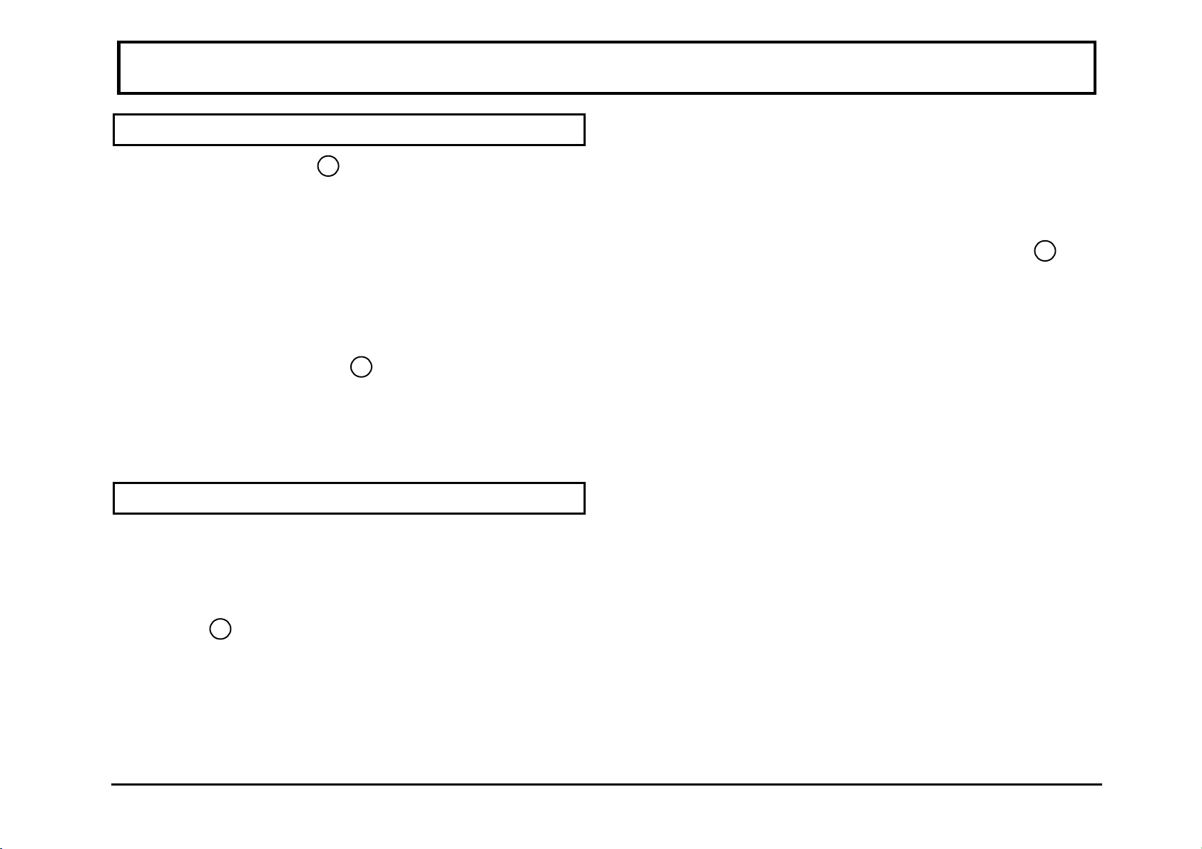
INSTALLATION Cyrus FM7
1. Audio Output
2. Antenna Input
3. MC-BUS System Connection
4. Power Switch
5. Mains Fuse
6. Power Inlet
English
Fig.1 Tuner (rear view)
4

Cyrus FM7 INSTALLATION
POSITIONING THE UNIT
The Cyrus FM7 may be positioned as a free standing unit
or alongside another piece of audio equipment. Never
stand the unit on top of a power amplifier, which may
generate heat. The Cyrus FM7 Tuner must always sit
horizontally on a flat firm surface.
CONNECTING THE UNIT
The Mains Supply
The moulded IEC connector of the mains lead supplied
should be plugged in to the power inlet
6
on the rear of
the unit.
The mains fuse
5
is located on the rear panel next to the
power switch. It must only be replaced with the following
types:
U.K. / Europe - 230V T100mA/20mm
N. America / Far East - 115V T200mA/20mm
In the U.K., the FM7 comes with the mains plug fitted. In
the unlikely event that the plug fuse should need replacing
ensure that it is only replaced with a 3 Amp Fuse.
Connecting to an Amplifier
Using the interconnect lead provided connect one set of
the phono plugs to their corresponding audio outputs on
the rear of the tuner
1
. The other end of the lead should
then be connected to the tuner input of your amplifier. If
there is no tuner input available any line level input may
be suitable. Ensure that the left and right channel sense are
correct between the tuner and the amplifier.
Connection of an External Aerial
This socket
2
is for use with a 75Ω external FM aerial.
The quality of the aerial you use will directly affect the
performance of your tuner. We would therefore advise
that you contact an aerial installation expert in your local
area or consult your dealer. In areas where FM cable
transmission is available the signal strength should be
generally quite adequate.
MC-BUS System Connection
This is an optional connection
3
which enhances and
expands the capability of specific Cyrus products,
including your FM7. Through the MC-BUS and certain
ancillary equipment a highly functional integrated system
with full remote control ability may be set up.
5
English

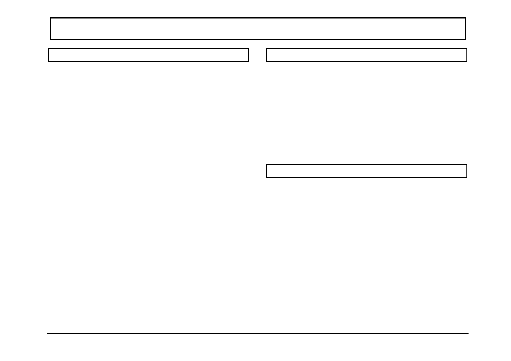
OPERATION Cyrus FM7
1. Standby Light
2. Fine
3. Remote Eye
4. Manual Tune
5. Presets (1-7)
6. Seek
7. Standby Switch
English
Fig. 2 Tuner (front view)
6
Cyrus FM7 OPERATION
POWER
The mains power switch
4
is located on the rear panel of
the tuner (refer to figure 1, rear panel drawing on page 4).
This switch should be left on for normal operation, except
when left unattended for a long period. In this case the
mains power should be switched off or the product
disconnected from the AC supply.
Refer now to figure 2, front panel drawing on page 6.
When the tuner is in regular use and power is permanently
applied, the STANDBY key
7
can be used to switch the
unit on and off. The standby light will show red when the
tuner is in standby and green when operating. The FM7
will also switch on if a preset station is selected.
SELECTING A BROADCAST STATION
To stop scanning press the SEEK key.
Manual Tuning
Manual tuning can be used to set to a known station
frequency or to lock to a weak transmitter, not detected in
auto tuning. Rotate the MANUAL tuning control
4
until
the required frequency is shown on the frequency display.
The frequency will change in steps of 0.1MHz, which is
the standard broadcast channel spacing for FM
transmission. When a station is correctly tuned to, the lock
indicator will be displayed. The signal strength can then
be read from the bargraph display (refer to page 9 for
detail).
Auto Tuning
Auto tuning will search automatically for stations with a
usable signal strength. To begin searching, press the
SEEK key
6
and the tuner will scan up the frequency
range, locking to the next available station. Another press
will continue station scan. The station frequency and
signal strength can be read from the display. If the station
detected is already stored as a tuner preset, the preset
location will also be shown on the display.
7
English

OPERATION Cyrus FM7
FINE TUNING A BROADCAST
Certain commercial radio stations and some cable
broadcasts are prone to imprecision in their transmitted
carrier frequency. This may cause distortion and will
detract from ultimate sound quality. In such instances and
for precise station alignment, fine station tuning is made
available.
Fine Tuning
To fine tune a broadcast station, first locate your station
using either AUTO or MANUAL tuning. Ensure that the
lock indicator on the display is showing. Press the FINE
key
2
. Now the manual tuning control can fine tune the
station in steps of just 10kHz. Whilst fine tuning, the
bargraph display switches to show a "magic eye" tuning
meter. For precise station tuning the black bars on each
side of the display should be of equal length. Press the
FINE key again to cancel fine tuning mode. Note that fine
tuning will cancel automatically if no adjustment is made
within a 5 second period. For more detail on fine tuning
refer to page 10.
PRESET STATION STORAGE
Seven preset memories are readily available on the front
panel which may be programmed with your favourite
stations.
Storing a Preset Station
To store a preset station, first locate the station using
either AUTO or MANUAL tuning methods as described
before, followed by fine tuning if necessary. Press and
hold a PRESET key for about two seconds until the
display blinks. The station is now stored in this preset
location. The memory of the FM7 will retain preset
stations indefinitely and requires no back up-batteries.
Note that the same station stored in two locations will
always show the lowest preset number on the display
indicating double storage of the same frequency. In this
case one of the preset locations can be re-programmed.
Tuning to a Preset Station
To recall a station from the preset memory, press the
desired PRESET key briefly. If no station is present, the
frequency digits will read zero and the search arrows will
flash briefly.
English
8

Cyrus FM7 OPERATION
Front Panel Display
1. Lock Indicator
.........................
This symbol indicates that the tuner has locked to a
station.
2. The Bargraph
a. Signal Meter Mode
..............
This symbol indicates the received signal strength of a
tuned station.
b. Magic Eye Mode
..................
(Fine tuning only)
The magic eye indicates the accuracy with which the unit
is tuned to the transmitted frequency. The display
illustrated shows optimised tuning.
3. Search Indicator
.........................................
The arrow is displayed when the tuner is searching up for
the next station.
4. Stereo
.........................................................................
This symbol indicates when a broadcast station is
transmitting in stereo.
5. Frequency Display
..................................
This shows the nominal broadcast frequency that the unit
is currently tuned to. In fine mode, a further digit is
displayed for 10kHz resolution.
6. Preset Number ........................................................
This digit shows the current preset number.
9
English

ADDITIONAL INFORMATION Cyrus FM7
µ
KNOW YOUR
FM7
The Bargraph
The signal strength bargraph and "magic eye" tuning
indicator of the FM7 can be used for accurate assessment
of signal quality at the antenna terminals. At Mission, our
automated test procedure enables each segment of the
display bargraph to be individually calibrated for signal
strength and tuning deviation. The calibration data is then
stored in a digital memory for recall each time power is
applied to the tuner.
When reading signal strength, the bargraph reads from 20
dBµV to 60dBµ V in 2dBµV steps.
Optimised Fine Tuning
De-tuned + 30kHz De tuned - 40 kHz
The Frequency Display
The FM7 frequency display will always read the
published nominal station frequency. An exception to this
is when fine tuning is selected when an extra digit
displays 10kHz steps for ultra accurate tuning. This can
now be stored.
When this station is selected the FM7 will display the
rounded frequency to match the advertised nominal
frequency.
Other Features
The Signal Meter Scale (dB
V)
When set for fine tuning however, the bargraph will
indicate station deviation in steps of 10kHz (two segments
per step). The following illustrations show different
examples of tuning alignment.
English
10
The FM7 is equipped with a high performance active pilot
tone suppression circuit. This ensures superb rejection of
subcarrier related spuriae, whilst providing a direct path
for audio signals.
Four power regulators supply the RF, PLL, Audio and
Control circuit modules of the FM7 independently.

Cyrus FM7 ADDITIONAL INFORMATION
CYRUS REMOTE COMMANDER
The Cyrus Remote Commander which is available as an
optional extra, is a unified handset designed to
complement the full range of Cyrus electronics including
your FM7. The distinctive Cyrus Commander replaces
individual product handsets where supplied, with a view
to providing additional functionality and enhanced
ergonomics.
TUNER MAINTENANCE
There are no serviceable parts in the Cyrus FM7, so there
is no reason to remove any of the panels. After
disconnecting the power supply, the cabinet may be
cleaned using a chamois leather, slightly moistened with
water. DO NOT use cleaning agents containing alcohol,
spirits, ammonia or abrasives.
THE MISSION/CYRUS GROUP MANUFACTURE:
• Loudspeakers
• Loudspeaker Stands
• Loudspeaker Cables
• Compact Disc Players
• D-to-A Converters
• Amplifiers
• Tuners
• Regulated Audio Power Supplies
• Isoplat (Vibration Isolation Platform)
11
English

TROUBLE SHOOTING Cyrus FM7
TROUBLE SHOOTING GUIDE
If you suspect that your FM7 is not operating to
specification, please read through this section before
returning the tuner to your local dealer.
No Sound from either Speaker
• Check that the amplifier is on.
• Check the tuner input of your amplifier is selected.
• Check the interconnect cable is connected correctly,
on both FM7 and the amplifier.
No Lights or Display
• Check that the power switch on the rear panel is
turned on.
No Display
• If you have a remote handset, then press the
DISPLAY key to turn the display on again.
FM7
will not Tune to Stations in SEEK Mode
• Make sure that the antenna is connected to the
75Ohm socket on the rear panel and that stations can
be tuned manually.
All Stations have High Background Noise
• Check the correct connection of your antenna. If the
problem persists there may be a bad connection in
the antenna connector.
Some Stations have High Background Noise
• These may be weaker or more distant stations and
therefore may require adjustment to the antenna
direction for optimum reception.
• Do bear in mind that there is a big difference in the
sensitivity of FM antennae available on the market,
and that your current antenna may need upgrading.
• Proximity to appliances with potential for high
frequency radiation may cause interference with high
quality reception in certain frequency bands. If you
own CD players, computers and similar devices
experiment by removing them from the mains and rechecking the noisy station.
No Stereo Indication
• Check other stations for stereo reception. the
particular broadcast may be in mono. For example
speech, commentary, etc.
English
12
Cyrus FM7 SPECIFICATION
AUDIO PERFORMANCE
Audio Output (95% mod. mono 1kHz) ..................775mV
Sensitivity (75 Ohm Input)
Mono, 50dB S/N ...................................................12dBµV
Stereo, 50dB S/N...................................................30dBµV
Selectivity................................................................... 55dB
Capture Ratio ............................................................1.5dB
IF Suppression............................................................90dB
Image Frequency Suppression................................... 80dB
Pilot Tone Suppression ..............................................68dB
Stereo Separation .....................................................>50dB
S/N Ratio, mono/stereo (CCIR-ARM) .................83/76dB
POWER SUPPLY
Voltage
See the plate attached to the rear of the unit
Power Consumption
Standby ......................................................................... 4W
ON.............................................................................. 7.6W
Safety Requirements................................................IEC 65
CABINET
Dimensions (WxHxD).........................215 x 73 x 360 mm
Weight....................................................................... 2.7Kg
Material............................................ Magnesium alloy and
Aluminium alloy
The company reserves the right to change this specification without prior notice.
1kHz THD @ 50kHz DEV. (A-WTD)
mono/stereo...................................................... 0.05/0.08%
Aerial Input ............................................... 75 Ohm coaxial
13
English
Part No. TU-MANUL/Iss.03-9412 File:7CEN5331.WIM

GUARANTEE Cyrus FM7
This guarantee only becomes effective if the guarantee
card enclosed is completed by the Dealer and the
purchaser and returned to MISSION or Distributor within
8 days of purchase.
This guarantee excludes:
i) All damage caused through accident, misuse, wear
and tear, neglect or through incorrect installation,
adjustment or repair by unauthorised personnel.
ii) Liability for damage or loss occurring in transit to or
from the purchaser.
Claims under this guarantee must, whenever possible, be
made through the Dealer from whom the equipment was
purchased or if that is not convenient, through another
authorised MISSION/CYRUS dealer.
MISSION shall not be liable for any consequential
damage, loss or injury whatsoever, arising from or in
conjunction with this equipment.
The cost of carriage (to or from the Dealer) shall be borne
by the purchaser.
This guarantee is personal to the original Purchaser and is
not transferable.
If equipment is found on examination to comply with the
published specification, MISSION reserves the right to
make a charge for examination and for return carriage.
No Dealer or Distributor has any authority to vary the
terms of this guarantee.
Any unauthorised servicing will result in loss of
guarantee.
We strongly recommend that you retain the sales receipt
for your CYRUS equipment in case of any warranty claim.
The above conditions do not affect your statutory rights as
a consumer.
English
14

Cyrus FM7 NOTES
Use the following table to record your local FM stations and their corresponding locations stored in your FM7
Preset
Number Frequency Station Name
Preset
Number Frequency Station Name
15
English
 Loading...