

Cyrus CD6s Service Manual

SERVICE MANUAL
SPECIFICATIONS
Audio output 2.1Vrms
Frequency response 20Hz-20kHz
Distortion <0.002%, (ref. 1kHz, 0dB)
S/N ratio 110dBA
Dynamic range >100dB (20Hz-20kHz)
Channel separation >110dB (1kHz), >90dB (20kHz)
Digital output Optical SPDIF
Clock jitter <100ps
Dimensions (H x W x D) 73 x 215 x 360 (mm), 2.8 x 8.4 x14.1 (inches)
Weight 3.1kg
CYRUS CD6s
CD PLAYER
17
59:57
CD 6 s
CYRUS CD6s SERVICE CAUTIONS
© Cyrus Audio Ltd Mar 2006 Cyrus CD6s Service Manual Issue 1
These two symbols shown are displayed prominently on the Cyrus CD6s base
cover label. They indicate that the following cautions must be observed by all
personnel-
CAUTION: TO REDUCE THE RISK OF ELECTRICAL SHOCK, DO NOT REMOVE COVER OR BACK.
THERE ARE NO USER SERVICEABLE PARTS INSIDE THE PRODUCT.
ALWAYS REFER SERVICING TO QUALIFIED SERVICE PERSONNEL.
CAUTION! LIVE MAINS VOLTAGES!
When undertaking any work on the CD6s, engineers should observe that exposed live
mains voltages exist on the PCB attached to the mains inlet socket. For safety, this area
must be securely insulated with insulation tape during all repair work.
STATIC PRECAUTIONS
When servicing any Cyrus product, adequate care must be taken during any service work
to observe static precautions, particularly when storing, handling or fitting replacement
components. The following guidelines must be observed –
• Check that all component purchases are delivered in static-safe packaging.
• Store all components in a static-safe environment.
• Always wear a grounding strap and work on a grounded bench when handling
components or servicing a product. Static damage may not be immediately obvious
and may result in a delayed action component/product failure.

CYRUS CD6s SERVICE CAUTIONS
© Cyrus Audio Ltd Mar 2006 Cyrus CD6s Service Manual Issue 1
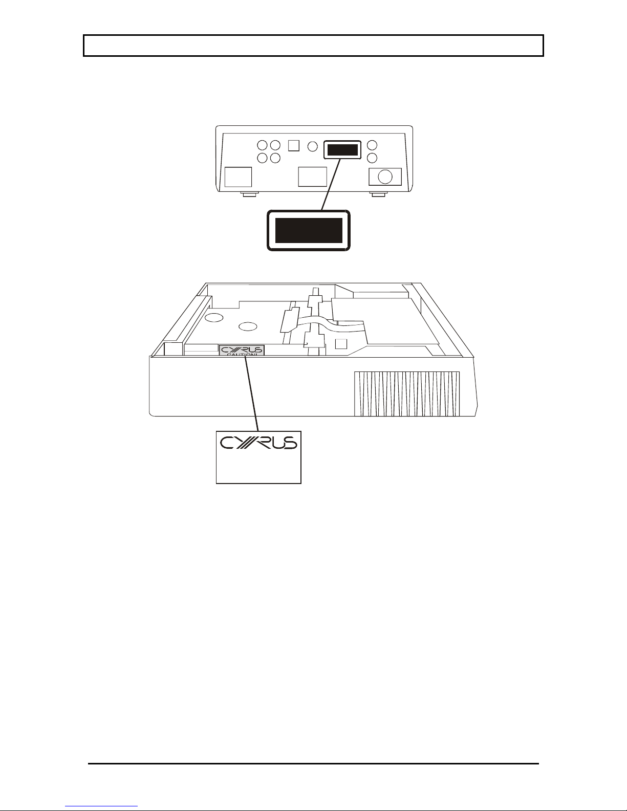
The notice below shows the position of caution labels which alert the service technician to the
presence of a laser device –
CLASS 1
CLASS 1
LASER PRODUCT
LASER PRODUCT
CAUTION!
VISIBLE AND INVISIBLE LASER
RADIATION WHEN OPEN. AVOID
DIRECT EXPOSURE TO BEAM

CYRUS CD6s SERVICE MANUAL INDEX
© Cyrus Audio Ltd Nov 2006 1 Cyrus CD6s Service Manual Issue 2
INDEX
SMD component replacement......................2
Type identification .......................................4
Block diagram ..............................................5
Technical description ...................................6
Fault finding/disassembly ............................8
Alignment...................................................10
Control software.........................................11
Use with a PSX-R.......................................12
MCBus operation .......................................13
Chassis parts drawing.................................14
Chassis parts list......................................... 16
Front panel parts drawing/list..................... 17
PCB parts lists ............................................18
Circuit diagrams .........................................26

CYRUS CD6s SMD COMPONENT REPLACEMENT
© Cyrus Audio Ltd Nov 2006 2 Cyrus CD6s Service Manual Issue2
Handling
SMD resistors and capacitors are widely used in the Cyrus range of products. When handling
SMD components, certain precautions should be observed-
Handling SMD resistors and capacitors
• Always store SMD components in their original packaging or in a cool dry environment.
• Always handle SMD resistors and capacitors with tweezers or a vacuum pencil.
• Never handle SMD resistors and capacitors with fingers.
• Hold the SMD component by the body, not by the ends.
• Do not use SMD resistors or capacitors if the ends are dirty or discoloured.
• Do not use SMD resistors or capacitors if they have been dropped on the floor- they may be
internally damaged.
• Always use replacement components of the correct size and shape. SMD components are
available in many different packages. Where possible, order original parts from Cyrus.
Handling SMD ICs
• Always store these components in their original packaging or in a cool dry environment.
• Always handle SMD transistors and ICs with tweezers or a vacuum pencil.
• Never handle SMD transistors and ICs with fingers.
• Ensure that the connection pins of larger multi-pin ICs are not deformed or damaged before
fitting.
Measuring circuits with SMD capacitors and resistors
• Avoid using sharp, pointed probes directly on the component end caps.
• Measure voltages from the PCB pad next to the component.
Static precautions
SMD components, particularly ICs, may be damaged by the static levels present in the
workshop. Damage caused by static may not immediately cause component failure but could
cause partial damage and a possible failure in the future. Observing these simple SMD
precautions will avoid product failures related to static damage-
• Always wear a grounded wristband when replacing any electronic components.
• Always store components in their original packaging or conductive plastic bags.
• Never store components in plastic trays or bags without protection.
Soldering/desoldering SMD components
• Never re-use old SMD components after de-soldering!
• Always apply solder heat directly to the contact area. Avoid over-heating adjacent
components.
• Always repair SMD PCBs with the correct tools. SMD components can only be replaced
with a hot air pencil or soldering iron designed for SMD components, preferably with
temperature control.
• Keep the soldering temperature as low as possible. 260ºC is recommended for SMD rework.
Most SMD components will withstand 260ºC for 5 to 10 seconds
• Use tin/lead/silver solder which has a lower melting point (about 179ºC). Tin/lead/silver
solder paste or small gauge solder (26SWG) is recommended.

CYRUS CD6s SMD COMPONENT REPLACEMENT
© Cyrus Audio Ltd Nov 2006 3 Cyrus CD6s Service Manual Issue 2
• When using solder paste a pressure dispenser should be used to ensure the correct amount of
solder is applied to each pad.
• Solder paste should not be used with direct heating methods as the solder between
component pins may not be melted.
• If necessary, remove excess solder paste with solder braid.
Removing SMD resistors and capacitors from the PCB with a soldering iron
1. Fit the soldering iron with a tip large enough to bridge both ends of the component.
2. Place the soldering iron so that its flat tip will heat both ends of the component at once.
3. When the solder melts, remove the component with tweezers.
4. Allow the PCB to cool for a few minutes, removing any excess solder with desoldering
braid.
Fitting replacement SMD resistors and capacitors to the PCB with a soldering iron
1. Apply a little flux to the connections.
2. Place the component in position.
3. Tin the soldering iron, bring the tip into contact with the PCB pad and flow solder to the
joint. Avoid bringing the soldering iron tip directly into contact with the component.
Removing SMD ICs from the PCB
1. Using fine tipped side cutters or tweezer cutters, snip all the leads of the device and remove
the IC body.
2. Desolder the leads from the PCB pads.
3. Clean up the PCB with solder braid.
Removing SMD ICs with a hot air SMD tool
1. Fit a suitable size tip for the IC being removed.
2. Heat the IC evenly until the solder melts.
3. Remove the IC with tweezers.
Fitting replacement ICs to the PCB with a soldering iron
1. Check that the pins of the IC are not distorted.
2. Using tweezers, position the IC over the footprint.
3. Check that all the IC pins are correctly aligned with the pads.
4. With a very fine tip soldering iron, solder in the pins at the corners of the IC.
5. Re-check the alignment and correct if necessary.
6. When the alignment is OK, solder the remaining pins of the IC to the PCB.
CYRUS CD6s TYPE IDENTIFICATION
© Cyrus Audio Ltd Nov 2006 4 Cyrus CD6s Service Manual Issue2
Rating label
Each Cyrus CD6s carries a rating label on the rear panel, which includes details of the
following:
Nominal power voltage
This will be either 230V For use on nominal 220V - 240V AC mains supply.
115V For use on nominal 110V - 120V AC mains supply.
Power consumption
The power consumption figure is indicated under normal working conditions.
Serial number
Each Cyrus CD6s carries a serial number code, which identifies the following-
• Type of product
• Market destination
• Build number
• Paint finish (colour)
The serial number is on the baseplate. It is therefore important to ensure that a baseplate
removed from a product is re-fitted to the same product. In any communications with Cyrus
Service or Quality departments it is essential that the full serial number is quoted so that original
specification parts and service information may be supplied.
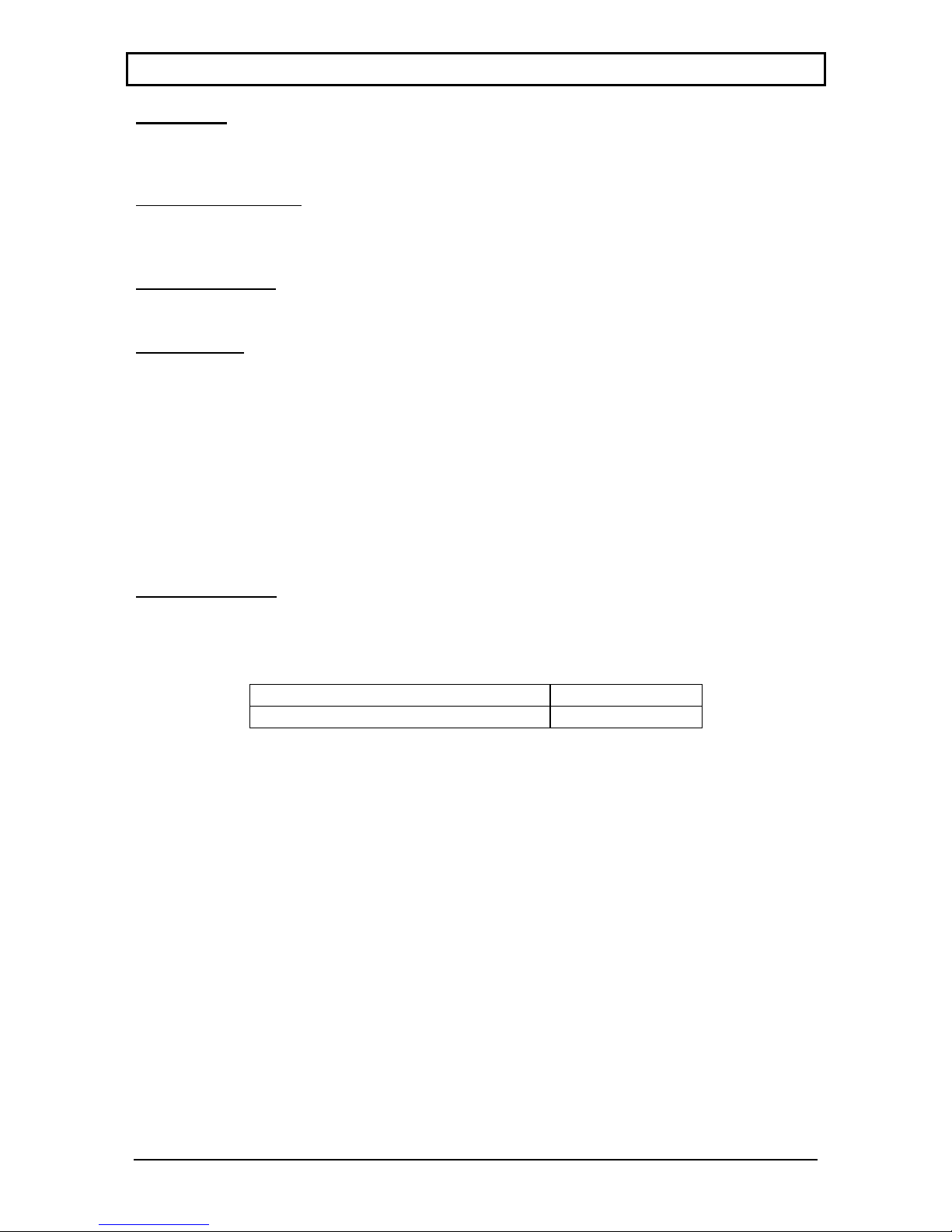
PCB Identification
The Cyrus CD6s PCB is marked with a design revision number and this number should be
quoted in all correspondence to the service department when requesting technical advice or
requesting spare parts. The table below shows the PCB markings.
Revision number PCB marking
Main board revision 2 IS101332
CYRUS CD6s BLOCK DIAGRAM
© Cyrus Audio Ltd Nov 2006 5 Cyrus CD6s Service Manual Issue 2
RAD
FOC
MOT
AM2088
AM2088
TDA1300
SAA7327
BCLK
BCLK
WCLK
WCLK
DATA
DATA
XCLK
DSA
KEYS
IR
DISPLAY DATA
SPI
H8/3644
Microcontroller
74HC14
Buffer
74HC4046
PLL
74HCT86
Data buf fer
and
74HC574
Latch
L
R
DAC
PCM1738
LCD
IR
Keys
IC502
IC204
IC202
IC201
/Reset
IC503
DS1811R-15
IC301
IC501
MC BUS
SPDIF ( )
OPTICAL
IC101
AK4103
Main PCBServo
PCB

CYRUS CD6s TECHNICAL DESCRIPTION
© Cyrus Audio Ltd Nov 2006 6 Cyrus CD6s Service Manual Issue2
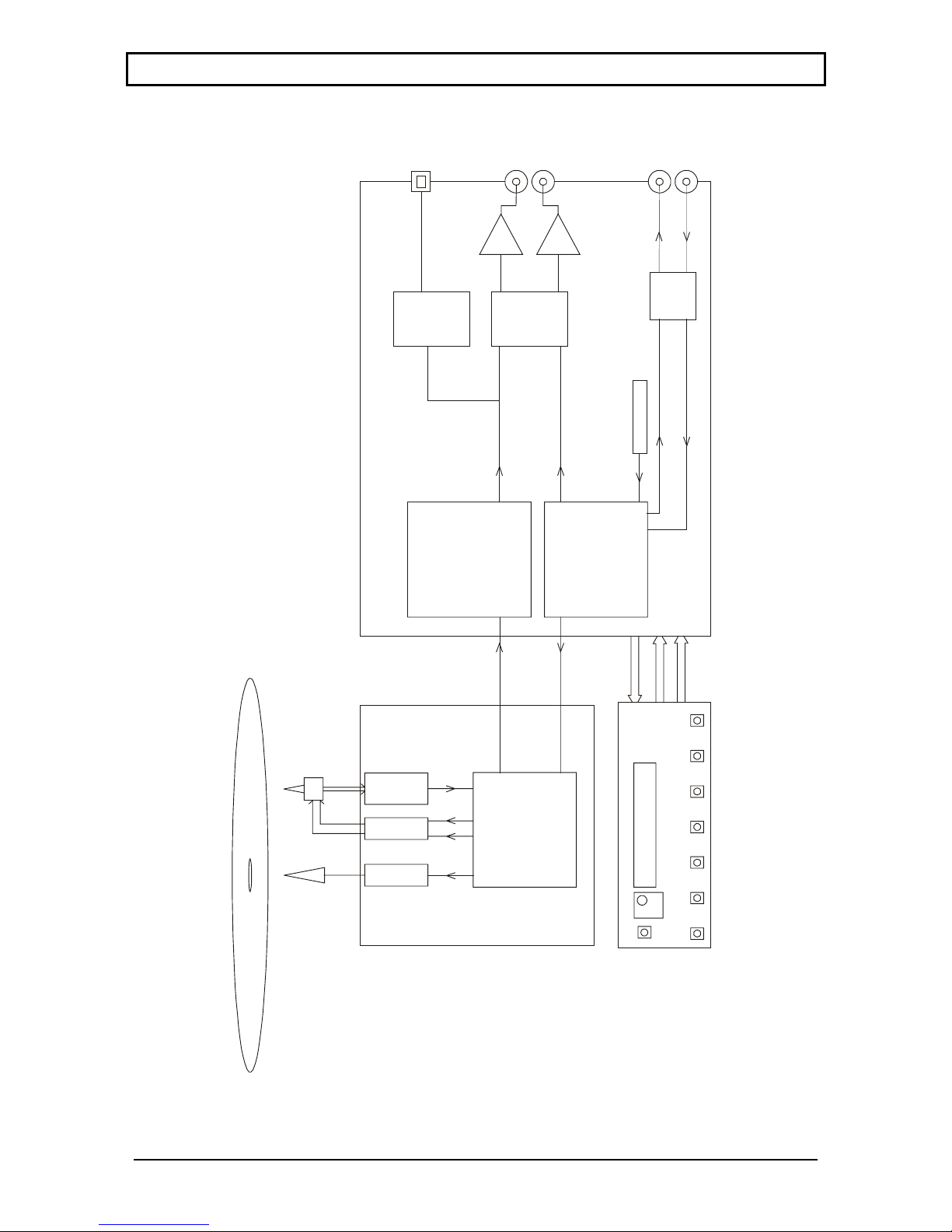
Cyrus CD6s PCB assemblies
The following is a brief description of the two internal PCBs found in the CD6s.
The servo PCB is located just under the base plate, this includes the CD tray motor and sled
drivers, the laser servo microcontroller and CD decoder.
The main PCB is mounted under the servo PCB in the base of the chassis and contains
regulated power supplies, DtoA converter, optical SPDIF output and the user interface
microcontroller.
Microprocessor control system
System control for the CD6s is provided by microcontroller IC502 (H8/3644). The
microcontroller accepts external user commands (IR handset, front panel keys and MCBus loop)
and translates them into instructions that operate the CD mechanism, via the servo PCB.
The microcontroller communicates with the servo PCB via the bi-directional serial data bus
(marked ‘DSA’ on the circuit diagrams), where the operational status of the CD mechanism is
communicated back to the microcontroller and displayed on the LCD.
IC503 (DS1811R-15) is a power supply voltage supervisor for the microcontroller. If the power
supply voltage drops below 4.3V it will reset the microcontroller.
Control Software
The software contained in the microcontroller is electrically programmed into the internal flash
memory when the CD6s are manufactured. This software may be updated at an authorised
Cyrus service centre as later versions are released.
Note. If IC502 is replaced for any reason, new software must be installed after the replacement
microcontroller is fitted.
The software version may be checked from the front panel of the CD6s by using the following
key sequence -
1. Connect power to the CD6s and set to Standby (power light red).
2. Press and hold the Standby key.
3. The software version and release date will be shown on the display.
Disc reading/decoder module and servo PCB
The disc reading laser pickup is a Philips VAM1202/12 mounted in a motor driven tray loader,
which receives its operating commands via the servo PCB.
Note. The laser pickup and servo PCB are not serviceable items. If either of these parts is
defective it must be replaced with original parts from the Cyrus spares department.
Digital to Analogue conversion
The digital audio data from the servo PCB is fed to the main PCB via cable assembly CON102.
The data is then buffered by IC201 (74HCT86) and reformatted by IC202 (74HC574) before
being input to the DAC (IC301 (PCM1728)). The balanced DAC outputs are passed through I/V
converters IC302/3 (BA5523) and then buffered by IC304 (OPA2134) to the left and right audio
outputs.

CYRUS CD6s TECHNICAL DESCRIPTION
© Cyrus Audio Ltd Nov 2006 7 Cyrus CD6s Service Manual Issue 2
The DAC master clock is generated by the PLL circuit IC204 (74HC4046) and divided by shift
register IC205 (74HC161). O/P Pin11 (÷16) XCLK/8 = 2.1168MHz.
O/P Pin14 (÷2) XCLK = 19.99344MHz.
The DAC regulated power supplies are derived from the low voltage secondary windings: +5V
(VR604) and +3.3V (VR301).
Digital Optical output
The reformatted data from IC202 (74HC574) is converted to SPDIF format by the digital audio
output encoder IC101 (AK4103) then fed to the optical output (TOTX101).
Power supplies
The internal regulated power supplies for the Cyrus CD6s are derived from the high and low
voltage secondary windings from a single toroidal transformer.
The low voltage windings supply regulated +5V supplies to digital circuitry including the PLL,
DtoA converter, microcontroller and CD mechanism.
The high voltage windings supply regulated ±15V supplies to the analogue audio stages and a
+9V supply to the servo control motors for CD mechanism.
Front panel display
The front panel display is a backlit LCD module mounted in a moulding behind the front panel.
The LCD module is driven by signals from microcontroller IC502 pins 52 and 53 (LCD_DATA
and LCD_SCLK). IC502 also reads back an analogue voltage encoded from keys pressed on the
front panel (via KEYS_IN1 pin 64), and remote control information from the eye via line
REMOTE_IN pin 43.
 Loading...