

Page 1

UserInstructions
Cyrus7
Page 2
Cyrus 7
aabbccddeeffgghhii1)1)1!
TP1 IN
TP2 IN
L
R
AV
AU2AU1AVTU
TP1 INTP2 IN
PRECISION
ELECTRONIC
INSTRUMENT
HEADPHONES
ENGLAND
AU1 AU2 TP1 TP2
MADE IN
+
CAUTION:REPLACE WITH
SAME TYPE FUSE.
ATTENTION: UTILISER UN
FUSIBLE DE RECHANGE DE
FUSE: T1A/250V
230V-50/60Hz @ 200W
Fig 1
1
BI-WIRE
R-CH
2
MEME TYPE
BI-WIRE R-CH
OUT
MC-BUS
-
NI
MUTE PHONES
CD
PRE OUT
L
PRE OUT TP OUT
R
TU
TP OUT
1@
CD
L
USE
CD
R
LON Y
-RPSX
AV TUAU2 AU1
1$1%1^1&
BI-WIRE L-CH
1
BI-WIRE
-
+
L-CH
2
1#
(a)
(b)
(c)
Fig 4
LHC = RHC
RHC =+1dB
LHC Only
(a)
Fig 5
-2dB
(b)
0dB
(c)
Cyrus 7
Fig 2
f
e
b
c
1)
1!
1@
1#
1#
1@
1!
Commander
CD
AU1TUAU2AVTP
123
47586
9
0STORE
OFF
MUTE
d
1%
h
g
a
1^
1$
1&
1*
1(
2)
(a)
Cyrus CD Player
Cyrus FM Tuner
TPOUT
PREOUTLTP2IN
BI-WIRER-CH
OUT
L
1
BI-WIRE
+
R-CH
2
CAUTION:REPLACEWITH
SAMETYPE FUSE.
ATTENTION:UTILISERUN
FUSIBLEDE RECHANGE DE
MEMETYPE
FUSE:T1A/250V
230V-50/60Hz@ 200W
MC-BUS
TP1INTP2IN
PREOUT TPOUT
R-R
NI
TP1IN
AU2AU1AVTU
PRECISION
ELECTRONIC
INSTRUMENT
HEADPHONES
MADEIN
ENGLAND
+2dB
MUTE
L
AV TUAU2 AU1
R
USE
LONY
-RPSX
CD
CD
BI-WIRE
-
L-CH
Fig 6
Fig 7
BI-WIREL-CH
1
+
2
Fig 3
Cyrus 7
Cyrus Power
Cyrus 7
Page 3
User Instructions Cyrus 7
IMPORTANT! Read before operating this equipment!
CAUTION:
to important instructions and safety procedures in this
manual.
ATTENTION:
electrical shock presented by components inside this
product. Unauthorised personnel must not open this unit
WARNING:
covers or panels. There are no user serviceable parts in this product.
WARNING:
equipment to rain or moisture.
HEED WARNINGS:
instructions should be adhered to.
READ ALL THE INSTRUCTIONS:
should be read before the product is operated.
RETAIN INSTRUCTIONS:
retained for future reference.
FOLLOW INSTRUCTIONS:
followed.
CLEANING:
liquid or aerosol cleaners. Use a damp cloth for cleaning.
WATER AND MOISTURE:
near a bath tub, wash bowl, kitchen sink, or laundry tub, in a wet basement; or
near a swimming pool and the like. The product must not be exposed to
dripping or splashing and no objects filled with liquids, such as vases, shall be
placed on the product.
HEAT:
radiators, stoves, or any other products (including amplifiers) that produce
heat.
VENTILATION:
to ensure reliable operation of the product and to protect it from overheating
and these openings must not be blocked or covered. The openings should
never be blocked by placing the product on a bed, sofa, rug or similar surface.
This product should not be placed in a built-in installation such as a bookcase
or rack unless proper ventilation is provided or the manufacturer's instructions
have been adhered to.
OBJECT OR LIQUID ENTRY:
product through openings as they may touch dangerous voltage points or
short-out parts that could result in a fire or electric shock.
ACCESSORIES:
bracket, or table. The product may fall, causing serious injury to a child or
adult, and serious damage to the product. Use only with a cart, stand, tripod,
bracket or table recommended by the manufacturer, or sold with the product.
Any mounting of the product should follow the manufacturer's instructions,
and should use a mounting accessory recommended by the manufacturer.
ATTACHMENTS:
manufacturer as they may cause hazards.
MOVING THE PRODUCT:
should be moved with care. Sudden stops, excessive
force, and uneven surfaces may cause the product and
POWER SOURCES:
power source indicated on the marking label. If you are not sure of the type of
power supply to your home, consult your product dealer or local power
company. For products intended to operate from battery power, or other
sources, refer to the operating instructions.
OVERLOADING:
convenience receptacles. This can result in an increased risk of fire or electric
shock.
The exclamation mark is to draw your attention
The lightning flash warns you of the risk of
.
To reduce the risk of electrical shock do not remove any unit
To reduce the risk of electric shock, do not expose this
All warnings on the product and in the operating
All the safety and operating instructions
The safety and operating instructions should be
All operating and use instructions should be
Unplug this product from the mains before cleaning. Do not use
Do not use this product near water - for example,
The product should be situated away from heat sources such as
Slots and openings in the cabinet are provided for ventilation,
Never push objects of any kind into this
Do not place this product on an unstable cart, stand, tripod,
Do not use attachments not recommended by the product
A product and cart combination
This product should be operated only from the type of
Never overload wall outlets, extension cords, or integral
POWER CORD PROTECTION:
they are not likely to be walked on or pinched by items placed upon
them, paying particular attention to cords at plugs, convenience receptacles,
and the point where they exit from the product.
NAKED FLAMES:
on this product.
LIGHTNING:
when it is left unattended or unused for long periods of time, unplug it from the
wall outlet and disconnect the antenna or cable system. This will prevent
damage to the product due to lightning and power-line surges.
CAUTION! POLARISED CONNECTOR (CANADA and USA):
To prevent electrical shock, match wide blade of plug to wide slot, fully insert.
Do not alter or remove this plug if it does not fit your mains power socket.
Have a suitable socket installed by a competent electrician.
No naked flame sources, such as candles, must be placed
For added protection for this product during a lightning storm, or
POWER SUPPLY:
Connect the moulded IEC connector of the AC cord supplied plugs into the
power inlet 1% on the rear of the unit. The mains fuse 1^ is on the rear panel
next to the power switch. It must only be replaced as follows:
U.K. / Europe 230V T1A 20mm
N. America / Far East - 115V T2A 20mm
The mains supply requirement for your Cyrus 7 is marked on a label on the
rear panel. Before connecting, check that this voltage is the same as your
mains supply.
230V Products: Voltage Range 220V-240V
115V Products: Voltage Range 110V-120V
If you move to an area with a different mains voltage, contact your local Cyrus
distributor to have your product converted.
Power supply cords should be routed so that
(Refer to Fig.1)
or
against
NOTE FOR UK CUSTOMERS:
The Cyrus 7 is supplied with a power cable terminated by a fused 13A mains
plug. This plug should not be removed but if it is removed, dispose of it safely
and do not re-use it. To connect a new 13A plug, proceed as follows: Connect
the brown wire to the terminal marked L or coloured red. Connect the blue
wire to the terminal marked N or coloured black. The internal plug fuse should
be 5A.
SERVICING
Do not attempt to service this product yourself as opening or removing covers
may expose you to dangerous voltage or other hazards. Refer all servicing to
qualified service personnel.
CONDITIONS REQUIRING SERVICE:
outlet and refer servicing to qualified service personnel when:
•
•
•
•
•
•
REPLACEMENT PARTS:
service technician has used replacements specified by the manufacturer or
have the same characteristics as the original part. Unauthorised substitutions
may result in fire, electric shock, or other hazards.
SAFETY CHECK:
ask the service technician to perform safety checks to determine that the
product is in proper operating condition.
PRODUCT SERVICE CENTRES
For product service or technical advice, contact only authorised Cyrus service
centres. The Cyrus distributors are listed at the end of this instruction manual.
:
Unplug this product from the wall
When the power supply cord or plug is damaged.
If liquid has been spilled, or objects have fallen into the product.
If the product has been exposed to rain or water.
If the product has been dropped or damaged in any way.
If the product does not operate normally by following the operating
instructions. (Adjust only those controls that are covered by the
operating instructions. Improper adjustment of other controls may
result in damage requiring extensive work by a qualified technician
to restore the product to its normal operation).
When the product exhibits a distinct change in performance.
When replacement parts are required, be sure the
Upon completion of any service or repairs to this product,
GB
GB
1
Page 4
Cyrus 7 User Instructions
Welcome to the world of
Congratulations on your choice of Cyrus Hi-fi products. Our state-of-the-art
design technology and outstanding quality of manufacture has won countless
awards around the world. We are confident that you will derive great pleasure
from owning a product from one of the most recognised and respected
manufacturers of hi-fi equipment.
Please read these instructions carefully before commencing installation. They
provide full guidance to help you install your Cyrus 7 safely and correctly.
Cyrus!
Preparations for Installation
Before installing the Cyrus 7 check that the following items are included in the
accessory box.
•
Warranty Card (with instruction manual)
•
Power Cable
•
Remote Handset
•
4 Loudspeaker Plugs
After removing these items, please retain the packaging.
Install the Cyrus 7 in a well ventilated location away from sources of high
temperature, dust or humidity. Never stand the Cyrus 7 under another unit or
on any surface likely to obstruct its cooling or ventilation.
INSTALLATION
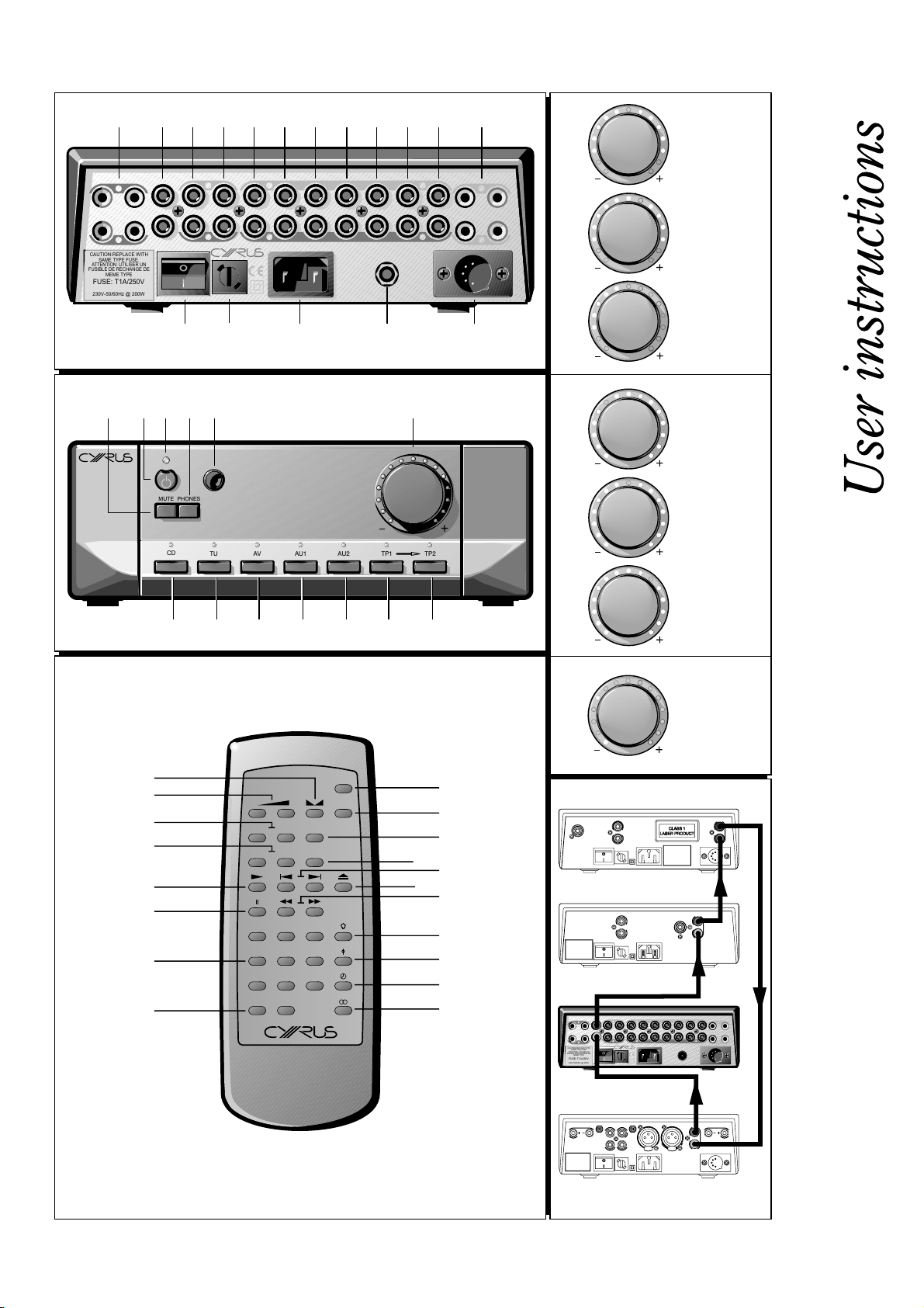
Key to the rear panel drawing:
1. Right Speaker Output
2. MC-BUS System Connection
3. Pre-Amplifier Output
4. Tape Recorder Output
5. Tape 2 Input
6. Tape 1 Input
7. Aux 2 Input
8. Aux 1 Input
(Refer to Fig 1):
9. AV Input
10. Tuner Input
11. CD Input
12. Left Speaker Output
13. PSX-R Connection
14. Headphone socket
15. Power Inlet
16. Mains Fuse Holder
17. Power Switch
Connecting to the AC Mains Supply
Connect the socket on the AC Power cable to the Power inlet 1% on the rear panel
of the Cyrus 7. Now connect the cable to a suitable AC power point.
The mains power switch 1& on the rear panel of the Cyrus 7 should be left on
for normal operation, except when left unattended for a long period when it
should be switched off or disconnected from the AC supply.
Connecting Signal Inputs
Connect a phono cable between each component and the sockets as marked
on the rear panel. Ensure left and right channels are correctly connected. The
Cyrus 7 has inputs for CD Player –CD 1!, a tuner - TU 1), a Home Theatre
decoder - AV i and two auxiliary inputs – AU1 h and AU2 g which can be
used to connect a wide variety of products. Check the specification of these
products before connecting to your Cyrus 7.
Connecting a Turntable
The Cyrus 7 is a line level amplifier. To play a turntable through your unit an
external phono pre-amplifier is required.
Connecting Tape/Disc recorders
A tape recorder may be connected to the Cyrus 7 in two ways- if a full tape
monitor circuit is required (for three-head cassette decks etc) connect the
tape recorder to TP2. If tape monitor is not required connection to the TP1
input is recommended.
To connect the tape recorder you will need two phono cables. Connect one
cable from the Output or Playback sockets of the tape deck to the appropriate
Tape Input – TP1 IN f or TP2 IN e of the Cyrus 7 and a second cable from
the Input or Record sockets of the tape deck to the Tape Record Output - TP
OUT d sockets of the Cyrus 7.
NOTE:- If the main system tape recorder is connected to TP2, a second tape
recorder may additionally be connected to TP1 for replay only. This facility
enables tape copies to be made from TP1 to TP2.
Connecting Headphones
The headphones socket t is a standard 6.35mm (¼") stereo jack socket for
connection to a pair of headphones. Headphones may be permanently
connected to the amplifier and selected when required with the front panel
switch.
Connecting Loudspeakers
Fit the supplied plugs to the loudspeaker cables making sure to line up + and
- at each end. Most cables have polarity indicators and may also be marked
for directionality. The + and - terminals of the Cyrus 7 must be connected to
the corresponding + and - terminals of the loudspeakers.
Ensure that the connections are secure, then connect the left and right
loudspeakers to the rear panel sockets a and 1@ of the Cyrus 7.
NOTE: The dual output sockets of the Cyrus 7 are provided for convenient
connection of bi-wiring speaker cables.
MC-BUS System
Connecting the MC-BUS sockets b of the Cyrus 7 in an MC-BUS system
provides unified system control. An MC-BUS loop is established by
connecting single phono cables from the MC-BUS output of one unit to the
MC-BUS input of another in a daisy-chain. Complete the loop by returning the
MC-BUS output of the final component to the MC-BUS input of the first.
With MC-BUS established you can control the power function of the entire
system from the Cyrus 7, from the front panel or remote control. Selecting
'CD' from the front panel will switch on the Cyrus 7, the Cyrus Power and a
Cyrus CD player. When the Cyrus 7 is set to Standby, the entire system will
also switch off.
When a Cyrus Surround Processor is in the MC-BUS loop, setting of the
volume calibration level will take place automatically when Cyrus 7’s AV input
is selected. Refer to the handbook for AV-master or AV5 for further details.
External Regulated Power Supply -
The PSX-R is a unique DC power supply which will upgrade the sonic
performance of your Cyrus 7 and enhance its current drive. When a Cyrus 7 /
PSX-R combination is installed, analogue and signal related sections of the
Cyrus 7 are powered from this clean, stable power source while other
requirements are supplied internally. This ensures complete isolation of
control circuits and sensitive analogue sections reducing AC mains-borne
noise and power supply ripple.
To connect the PSX-R to the Cyrus 7 plug the connector on the umbilical cord
of the PSX-R into the Multi-Pole socket on the rear of the Cyrus 7 (1# Fig.1)
You will need a mains supply for both units.
NOTE- When you add a Cyrus PSX-R to your system it is essential for your
Cyrus 7 to be modified by your dealer or an authorised Cyrus service
organisation. Connecting the Cyrus PSX-R to a Cyrus 7, which is not correctly
modified will result in a fault condition displayed on the Cyrus 7. (see page 4
for further details).
(Refer to figs 1 & 7)
PSX-R
GB
2
GB
Page 5
User Instructions Cyrus 7
OPERATION
Key to the front panel drawing:
1. Mute Switch
2. Standby Switch
3. Standby Light
4. Headphone Switch
5. Remote Eye
6. Level Control
7. TP2 Tape Monitor
(Refer to fig 2)
8. TP1 Input
9. AU2 Input
10. AU1 Input
11. Video (AV) Input
12. Tuner Input
13. CD Input
Power
When power is applied, the STANDBY key b is used for power control. The
Standby light c shows green when the Cyrus 7 is operating and glows red
when in standby mode. The Cyrus 7 will switch from standby to on, when any
input key h-1# is selected.
When the Cyrus 7 is switched on from the rear panel mains switch, it will
perform a self-test and wait in Standby mode.
When the Cyrus 7 is switched to Standby, all settings for input selection and
Volume/Balance are retained.
Selecting an Input
The INPUT SELECT keys h-1# switch selected input sources. When an input
key is selected, the red indicator above the key will turn on.
Tape/Disc Playback and Recording
Playback:
TP1 h (for a tape recorder connected to TP1) or TP2 g (for a tape recorder
connected to TP2). When TP2 is selected the indicator above the selected
key will light in addition to the selected source. To cancel TP2, press the TP2
key again. If the tape recorder has a three-head facility, selecting the TP2 key
will monitor the recording directly from the third head, whilst recording.
Recording:
and follow the recording instructions in your tape deck manual.
Copying:
to a tape recorder connected to the TP2 circuit of the Cyrus 7.
Note: You cannot record from Tape 2 to Tape 1.
Volume and Balance
The LEVEL CONTROL f of the Cyrus 7 performs the dual functions of
volume and balance.
Volume:
steps. The light ring around the knob is calibrated to show the current
loudness level. When the volume is at minimum the first indicator on the light
ring will be RED. As the volume increases a GREEN light moves clockwise
around the ring. The volume setting is stored when the unit is set to standby.
Balance:
change the mode of the front panel LEVEL CONTROL f to that of Left/Right
Balance. The light ring works in "reverse video" with the unlit section
indicating the position of L-R balance. You can alter L-R balance by up to +/4dB or switch one channel off when the control is turned to an extreme.
You can play back a recording by selecting the appropriate key
To record, select an input to record with the relevant Key i-s
Tape copies may be made when playing a tape from the TP1 input
(Refer to fig 4)
In normal mode the LEVEL CONTROL controls the volume in 1dB
Press the BALANCE control key on the remote control f to
Mute
Pressing the MUTE Key a will fade the volume to minimum level without
disturbing the existing setting. When muted the RED minimum level indicator
will light as well as the existing GREEN light to show that the output is muted.
Move the volume knob up or press the Mute key to fade back up to the
original volume setting.
Listening to headphones
To listen to headphones, press the PHONES key d. The MUTE light at the
bottom of the light ring will now glow orange. The speakers will now be muted
for headphone listening. Press the PHONES key d again to restore
loudspeaker operation.
NOTE: The HEADPHONES key d only operates when headphones are
connected to the rear panel socket of the Cyrus 7.
Caution:
If you have been listening to headphones at high volume, be sure to
turn the level down before you switch to normal loudspeaker operation.
Bi-amping / Tri-amping
The pre-amplifier output of the Cyrus 7 may be used in conjunction with
added power amplifiers to upgrade your loudspeaker system through Biamping or Tri-amping. The Cyrus range of power amplifiers is recommended
for this application.
Programmable Input Sensitivity
You may find an audible difference in level when switching from one input to
another due to the differing outputs of your source components. The unique
calibration memory of the Cyrus 7 can be programmed to match the
sensitivity of all inputs with reference to the CD input. To program an offset:
1. Select CD input and set the volume control to a comfortable listening
level.
2. Select the desired input and hold the input key down. The volume
display switches to show input offset.
3. Adjust the level to the same audible volume as the CD player. The
display will read the offset applied.
4. Press the input key again to store this setting.
Repeat Steps 2 - 4 for each input to set the appropriate sensitivity level.
Fig. 5(a) - 5(c) shows settings for Input Sensitivity levels set -2 dB, 0dB and
+2dB relative to the CD input respectively.
CYRUS AUDIO COMMANDER
To insert the batteries. Remove the battery cover on the rear of the handset.
Insert 2 AA batteries observing all the polarity markings. Replace the
compartment cover.
Operating the
Key to the Audio Commander drawing (Fig. 3)
Keys 1 -8 operate the
1. Select the AV input
2. Select CD or TU inputs
If you have a Cyrus CD Player or Cyrus FM7 Tuner, pressing a key will
switch the appropriate unit on together with the Cyrus 7.
3. Select AU1 or AU2 input
4. Select TP1 (hold key to select TP2)
5. Adjust Volume
6. Select BALANCE
7. Select MUTE
8. Switch OFF all Cyrus units
If CD or TU inputs have been selected with the Audio Commander, the
following keys 10-20 will control a Cyrus CD Player or the Cyrus
FM7/FM7.5 Tuner-
10. Select Play .................................................................. Cyrus CD Players
11. Select Pause ...............................................................Cyrus CD Players
12. Numeric Keypad...................................Cyrus CD Players & FM7/FM7.5
13. Store a Program .......................................................... Cyrus CD Players
Store a Preset .............................................................Cyrus FM7/FM7.5
14. Select FAST FWD / REV ............................................ Cyrus CD Players
Auto tune - SEEK UP / DOWN....................................Cyrus FM7/FM7.5
15. Select STOP / EJECT .................................................Cyrus CD Players
16. Select NEXT/PREVIOUS track ...................................Cyrus CD Players
Select Preset UP / DOWN ..........................................Cyrus FM7/FM7.5
17. Switch Display On / Off ........................Cyrus CD Players & FM7/FM7.5
18. Set Absolute Phase............................................. Cyrus dAD3 CD Player
Set Repeat .......................................................... Cyrus dAD1 CD player
19. Select Elapsed Time / Time remaining ....................... Cyrus CD Players
20. Select MONO / STEREO ............................................Cyrus FM7/FM7.5
Audio Commander
Cyrus
Cyrus 7
(Refer to fig 5)
(Refer to Fig 3)
GB
GB
3
Page 6
Cyrus 7 User Instructions
TROUBLESHOOTING GUIDE
If your Cyrus 7 is not operating properly, disconnect the power and check
carefully all connections.
If you are in any doubt, consult your dealer.
No sound
Amplifier switched off or in Standby
Mute is on (RED light on Vol. Ring)
Tape Monitor on (RED tape light)
Source not working
(e.g. CD not playing)
No sound from one loudspeaker
BAL control at extreme limit
Does your speaker have fuses?
Speaker cables / interconnects faulty
Spurious noises from speakers
Interconnects or connections faulty
No response from any keys
Switch off at rear panel, wait one minute and switch on.
The problem should clear
The Cyrus 7 has a unique fault indication system to help you to diagnose
problems. All fault indications appear on the Standby light on the front panel.
Fault indications at first installation of a Cyrus 7 with a PSX-R
Flashing Green
The Cyrus 7 is modified for
PSX-R but the PSX-R is not properly
connected
A PSX-R is connected to a Cyrus 7
which has not been modified to take
the PSX-R
Fault Indications during use
Flashing Green and Yellow
An overload condition usually
caused by excessive level or a
problem with your loudspeakers
Flashing Green
A fault condition has been reported
from the PSX-R
Flashing Red
An internal problem with Cyrus 7 or
PSX-R
Remote control not working
Remote control not operating
Remote control will not operate a
Cyrus CD player or tuner
If a fault condition still remains, return the Cyrus 7 (together with the PSX-R if
you are using one) to your Cyrus appointed dealer or an authorised Service
Centre.
Bring unit out of Standby
(Standby light - GREEN)
Deselect Mute
De-select Tape 2
See ‘Fault Indication System’
Centralise Balance
Check speaker, replace fuses
Check connections, cables -
replace if needed
Check, replace where necessary
Check PSX-R is plugged into Cyrus
7 and that both units are connected
to the mains
Unplug PSX-R, check Cyrus 7. If
Cyrus 7 works OK, return to dealer
for modification
Reduce level or Unplug speakers
amplifier should restore
Switch off power to both units, wait
one minute, switch on - amplifier
should restore
Switch off and on - amplifier should
restore
Check batteries
CD or TU button must be pressed
before sending a command
WARRANTY
The warranty card enclosed should be completed by the Dealer and the
purchaser and returned to CYRUS or its Distributor within 8 days of
purchase. No Dealer or Distributor may vary the terms of this warranty,
which is personal to the original Purchaser and is not transferable.
Please retain the sales receipt as proof of purchase.
Warranty claims must wherever possible be made through the Dealer
from whom the equipment was purchased.
This warranty excludes:
Damage caused through neglect, accident, misuse, wear and tear,
•
or through incorrect installation, adjustment or repair by
unauthorised personnel. Any unauthorised servicing will result in
loss of warranty.
Liability for damage or loss occurring in transit to or from the
•
purchaser.
Consequential damage, loss or injury, arising from or in conjunction
•
with this equipment.
Equipment for attention under warranty should be consigned return
carriage paid. If returned equipment is found to comply with the
published specification, CYRUS reserves the right to raise a charge.
The above conditions do not affect your statutory rights as a consumer
SPECIFICATIONS
Power Supply
Voltage: .......................................................................... As plate on rear of unit
Power Consumption
Standby .....................................................................................................(12W)
ON (No Load) ............................................................................................ (23W)
ON (2 x 50W/Ch)..................................................................................... (185W)
EMC & Safety Compliance............................................................................. CE
Enclosure
Dimensions (WxHxD) ............................................................ 215 x 75 x 365mm
Weight ....................................................................................................... 4.6Kg
Material......................................................................................Die cast chassis
Audio Performance
Input Sensitivity (50W/8Ω).............................. Line................................ 200mV
Input Impedance ............................................. Line.................................100kΩ
Frequency Response (-3dB) ........................... Line ......................... 4Hz, 90kHz
Signal to Noise Ratio (A-WTD) ....................... Line............................... 102dBA
Power Output (both channels driven).............. 8 Ohms.............................. 60W
THD+N (Pre-Amp) 1kHz ................................. Line............................. <0.002%
THD+N (1kHz, 2/3 power)............................... 8 Ohms....................... <0.003%
(both channels driven)
Cyrus reserves the right to change all specifications without notice. E &OE
.
GB
4
GB
 Loading...