

Page 1

CY8CKIT-042-BLE
Bluetooth® Low Energy (BLE)
Pioneer Kit Guide
Doc. # 001-93731 Rev. **
Cypress Semiconductor
198 Champion Court
San Jose, CA 95134-1709
Phone (USA): 800.858.1810
Phone (Intnl): +1.408.943.2600
www.cypress.com
Page 2

Copyrights
© Cypress Semiconductor Corporation, 2014. The information contained here in is sub ject to change wi thout no tice. Cypress
Semiconductor Corporation assumes no responsibility for the us e of any circuitry othe r than circuitry embodied in a Cypress
product. Nor does it convey or imply any license under patent or other rights. Cypress products are not warranted nor
intended to be used for medical, life support, life saving, critical control or sa fety applicati ons, unless pursu ant to an express
written agreement with Cypress. Furthermore, Cypress does not authorize its products for use as critical components in lifesupport systems where a malfunction or failure may reasonably be expected to result in significant injury to the user. The
inclusion of Cypress products in life-support systems application implies that the manufacturer assumes all risk of such use
and in doing so indemnifies Cypress against all charges.
Any Source Code (software and/or firmware) is owned by Cypress Semiconductor Corporation (Cypress) and is protected by
and subject to worldwide patent protection (United States and foreign), United States copyright laws and international treaty
provisions. Cypress hereby grants to licensee a personal, non-exclusive, non-transferable license to copy, use, modify, create
derivative works of, and compile the Cypress Source Code and derivative works for the sole purpose of creating custom software and or firmware in support of licensee product to be used only in conjunction with a Cypress integrated circuit as specified in the applicable agreement. Any reproduction, modification , translation, compilation, or representation of this Source
Code except as specified above is prohibited without the express written permission of Cypress.
Disclaimer: CYPRESS MAKES NO WARRANTY OF ANY KIND, EXPRESS OR IMPLIED, WITH REGARD TO THIS
MATERIAL, INCLUDING, BUT NOT LIMITED TO, THE IMPLIED WARRANTIES OF MERCHANTABILITY AND FITNESS
FOR A PARTICULAR PURPOSE. Cypress reserves the right to make changes without further notice to the materials
described herein. Cypress does not assume any liability arising out of the application or use of any product or circuit
described herein. Cypress does not authorize its products for use as critical components in life-support systems where a
malfunction or failure may reasonably be expected to result in significant injury to the user. The inclusion of Cypress’ product
in a life-support systems application implies that the manufacturer assumes all risk of such use and in doing so indemnifies
Cypress against all charges.
Use may be limited by and subject to the applicable Cypress software license agreement.
CySmart, F-RAM, PRoC, Programmable System-on-Chip, and PSoC Creator are trademarks and PSoC and CapSense are
registered trademarks of Cypress Semiconductor Corporation. All other products and company names mentioned in this
document may be the trademarks of their respective holders.
2
Purchase of I
Philips I
C components from Cypress or one of its sublicensed Associated Companies conveys a license under the
2
C Patent Rights to use these components in an I2C system, provided that the system conforms to the I2C Standard
Specification as defined by Philips. As from October 1st, 2006 Philips Semiconductors has a new trade name - NXP
Semiconductors.
Flash Code Protection
Cypress products meet the specifications contained in their particular Cypress Datasheets. Cypress believes that its family of
products is one of the most secure families of its kind on the market today, regardless of how they are used. There may be
methods, unknown to Cypress, that can breach the code protection features. Any of these methods, to our knowledge, would
be dishonest and possibly illegal. Neither Cypress nor any other semiconductor manufacturer can guarantee the security of
their code. Code protection does not mean that we are guaranteeing the product as “unbreakable.”
Cypress is willing to work with the customer who is concerned about th e integrity of their co de. Code p rotecti on is constantly
evolving. We at Cypress are committed to continuously improving the code protection features of our products.
CY8CKIT-042-BLE Bluetooth® Low Energy (BLE) Pioneer Kit Guide, Doc. # 001-93731 Rev. ** 2
Page 3

Contents
Safety Information 7
1. Introduction 9
1.1 Kit Contents..................................... ... ... ....................................... ... ... ... .... ..................9
1.2 Board Details ................................... ... ... ... .... ... ...................................... .... ... ... ... .... ...10
1.3 PSoC Creator™.........................................................................................................13
1.4 Getting Started...........................................................................................................14
1.5 Additional Learning Resources..................... ... ... ... ... .... ... ... ... .... ... ... ... ... .... ... ... ... .... ...14
1.6 Technical Support......................................................................................................16
1.7 Documentation Conventions......................................................................................16
1.8 Acronyms...................................................................................................................17
1.5.1 Beginner Resources.......................................................................................14
1.5.2 Application Notes...........................................................................................14
1.5.3 PSoC Creator Example Projects....................................................................15
1.5.4 Component Datasheets .................................................................................15
1.5.5 Bluetooth Learning Resources.......................................................................15
1.5.6 Learning From Peers .....................................................................................15
1.5.7 Other Related Resources...............................................................................16
2. Software Installation 19
2.1 Before You Begin.......................................................................................................19
2.2 Install Software ..........................................................................................................19
2.3 Uninstall Software......................................................................................................22
3. Kit Operation 23
3.1 Theory of Operation..................... .... ... ... ... .... ... ...................................... .... ... ... ... .... ...23
3.2 BLE Pioneer Kit USB Connection..............................................................................25
3.3 Placing Modules on Baseboard.................................................................................25
3.4 Programming and Debugging BLE Device................................................................26
3.5 Dongle Connection....................................................................................................29
3.6 USB-UART Bridge................................................................. .... ... ... ... ... .... ... ... ... .... ...31
3.7 USB-I2C Bridge.........................................................................................................32
3.8 Updating the Onboard Programmer Firmware ..........................................................34
3.9 Measure Coin-cell Power Consumption ....................................... ... ... ... .... ................34
4. Example Projects 37
4.1 Using Example Projects.............................................................................................37
4.2 Kit Test............ .... ... ... ... ... ....................................... ... ....................................... ... .......42
4.2.1 Project Description............................................................................ ... ... .... ...42
4.2.2 Hardware Connections...................................................................................43
4.2.3 Flow Chart......................................................................................................44
4.2.4 Verify Output..................................................................................................45
CY8CKIT-042-BLE Bluetooth® Low Energy (BLE) Pioneer Kit Guide, Doc. # 001-93731 Rev. ** 3
Page 4

Contents
4.3 CapSense Slider and LED.........................................................................................46
4.3.1 Project Description.................................. .... ... ... ... ....................................... ...46
4.3.2 Hardware Connections ..................................................................................48
4.3.3 Flow Chart .....................................................................................................49
4.3.4 Verify Output..................................................................................................50
4.4 CapSense Proximity..................................................................................................62
4.4.1 Project Description.................................. .... ... ... ... ....................................... ...62
4.4.2 Hardware Connections ..................................................................................63
4.4.3 Flow Chart .....................................................................................................65
4.4.4 Verify Output..................................................................................................66
4.5 BLE Central Mode.....................................................................................................72
4.5.1 Project Description.................................. .... ... ... ... ....................................... ...72
4.5.2 Hardware Connections ..................................................................................74
4.5.3 Flow Chart .....................................................................................................75
4.5.4 Verify Output..................................................................................................76
4.6 BLE Dongle and LED Control....................................................................................79
4.6.1 Project Description.................................. .... ... ... ... ....................................... ...79
4.6.2 Hardware Connections ..................................................................................79
4.6.3 Flow Chart .....................................................................................................80
4.6.4 Verify Output..................................................................................................81
5. Hardware 83
5.1 Pioneer Baseboard....................................................................................................83
5.1.1 PSoC 5LP......................................................................................................83
5.1.2 Power System................................................................................................83
5.1.3 Programming Interface ..................................................................................89
5.1.4 Expansion Connectors...................................................................................90
5.1.5 USB Mini-B Connector...... ... ... ... .... ... ... ... .... ...................................... ... .... ... ...94
5.1.6 CapSense Circuit...........................................................................................95
5.1.7 Pioneer Board LEDs......................................................................................97
5.1.8 Push Buttons .................................................................................................98
5.1.9 Cypress Ferroelectric RAM (F-RAM).............................................................99
5.1.10 Serial Interconnection Between PSoC 5LP and Bluetooth Module .............100
5.1.11 Bluetooth Module Headers ..........................................................................102
5.2 BLE Module Board ..................................................................................................103
5.2.1 PSoC 4 BLE or PRoC BLE..........................................................................103
5.2.2 Bluetooth Module Headers (20-Pin and 24-Pin Headers)........... ... ... ...........104
5.2.3 Wiggle Antenna ...........................................................................................105
5.2.4 Antenna Matching Network.. ... ... .... .......................................... ... .................106
5.2.5 BLE Passives...............................................................................................107
5.2.6 Test Points .................... .... ... ... ....................................... ... ... .... ... .................108
5.3 BLE Dongle Board...................................................................................................108
5.3.1 Power System..............................................................................................108
5.3.2 PRoC BLE ...................................................................................................109
5.3.3 Wiggle Antenna ...........................................................................................109
5.3.4 Antenna Matching Network.. ... ... .... .......................................... ... .................109
5.3.5 USB Type A Plug....... ... .... ... ... ... .... ... ... ....................................... ... ... ... .... ....110
5.3.6 System Status LED and Power LED............................................................ 111
5.3.7 User LED ..................................................................................................... 111
5.3.8 Push Buttons ............................................................................................... 112
4 CY8CKIT-042-BLE Bluetooth® Low Energy (BLE) Pioneer Kit Guide, Doc. # 001-93731 Rev. **
Page 5

Contents
6. Advanced Topics 113
6.1 Using PSoC 5LP as USB-UART Bridge ..................................................................113
6.2 Using PSoC 5LP as USB-I2C Bridge ......................................................................124
6.3 Developing Applications for PSoC 5LP ...................................................................132
6.3.1 Building a Bootloadable Project for PSoC 5LP. ... ... ... .... ... ... ... ... .... ... ... ... .... .132
6.3.2 Building a Normal Project for PSoC 5LP......................................................141
6.4 PSoC 5LP Factory Program Restore Instructions ...................................................142
6.4.1 PSoC 5LP is Programmed with a Bootloadable Application........................142
6.5 Using FM24V10 F-RAM...........................................................................................148
6.5.1 Address Selection........................................................................................149
6.5.2 Write/Read Operation ..................................................................................149
6.6 CySmart iOS Application .........................................................................................150
6.7 CySmart PC Tool.....................................................................................................158
A. Appendix 167
A.1 Schematics ..............................................................................................................167
A.2 Board Layout ...... ... ... ... ... ....................................... ... .... ... ... ... .... ... ... ... ... .... ... ...........175
A.3 Bill of Materials (BOM).............................................................................................183
Revision History 195
CY8CKIT-042-BLE Bluetooth® Low Energy (BLE) Pioneer Kit Guide, Doc. # 001-93731 Rev. ** 5
Page 6

Contents
6 CY8CKIT-042-BLE Bluetooth® Low Energy (BLE) Pioneer Kit Guide, Doc. # 001-93731 Rev. **
Page 7

Safety Information
The CY8CKIT-042-BLE boards contain electrostatic discharge (ESD)
sensitive devices. Electrostatic charges readily accumulate on the
human body and any equipment, which can cause a discharge without
detection. Permanent damage may occur on devices subjected to
high-energy discharges. Proper ESD precautions are recommended
to avoid performance degradation or loss of functionality. Store unused
CY8CKIT-042-BLE boards in the protective shipping package.
End-of-Life/Product Recycling
The end-of-life cycle for this kit is five years from the date of
manufacture mentioned on the back of the box. Contact your nearest
recycler to discard the kit.
The CY8CKIT-042-BLE Bluetooth Low Energy (BLE) Pioneer Kit is intended for use as a
development platform for hardware or software in a laboratory environment. The board is an open
system design, which does not include a shielded enclosure. For this reason, the board may cause
interference with other electrical or electronic devices in close proximity. In a domestic environment,
this product may cause radio interference. In such cases, the user may be requir ed to take adequate
preventive measures. Also, this board should not be used near any medical equipment or RF
devices.
The CY8CKIT-042-BLE Bluetooth Low Energy (BLE) Pioneer Kit is intended for use as a
development, demonstration and evaluation platform for hardware or software in a laboratory
environment. The kit is not intended for general consumer use. It generates, uses and can radiate
radio frequency energy. It has not been tested for compliance with the limits applicable under any
standard. Operation of the equipment may cause interference with radio communications, in which
case the user at his own expense will be required to take whatever measures may be required to
correct this interference. Cypress recommends that the kit only be used in a shielded room.
Attaching additional wiring to this product or modifying the product ope ration from the factory default
may affect its performance and cause interference with other apparatus in the immediate vicinity. If
such interference is detected, suitable mitigating measures should be taken.
CY8CKIT-042-BLE Bluetooth® Low Energy (BLE) Pioneer Kit Guide, Doc. # 001-93731 Rev. ** 7
Page 8

Safety Information
General Safety Instructions
ESD Protection
ESD can damage boards and associated components. Cypress recommends that the user perform
procedures only at an ESD workstation. If an ESD workstation is not available, use appropriate ESD
protection by wearing an antistatic wrist strap attached to a grounded metal object.
Handling Boards
CY8CKIT-042-BLE boards are sensitive to ESD. Hold the board only by its edges. After removing
the board from its box, place it on a grounded, static-free surface. Use a conductive foam pad if
available. Do not slide the board over any surface.
Battery Care and Use
■ Use the correct size and type of battery specified in this guide.
■ Keep battery contact surfaces and battery compartment contacts clean by rubbing them with a
■ Remove the battery from a device when it is not expected to be in use for several months.
■ Make sure that you insert the battery into your device properly, with the + (plus) and – (minus)
■ Do not place the battery next to metallic objects such as keys and coins.
■ Never throw the battery into fire.
■ Do not open up the battery.
■ Do not short the battery.
■ Do not subject the battery to high temperatures or high humidity.
■ Store the battery in a dry place.
■ Do not recharge a battery unless it is marked “rechargeable.”
clean pencil eraser or a rough cloth each time you replace batteries.
terminals aligned correctly.
Battery Disposal
Batteries can be safely disposed of with normal household waste. Never dispose of batteries in fire
because they can explode.
It is important not to dispose of large amounts of batteries in a group. Used batteries are often not
completely “dead.” Grouping used batteries together can bring these “live” batteries into contact with
one another, creating safety risks.
8 CY8CKIT-042-BLE Bluetooth® Low Energy (BLE) Pioneer Kit Guide, Doc. # 001-93731 Rev. **
Page 9

1. Introduction
Thank you for your interest in the CY8CKIT-042-BLE Bluetooth® Low Energy (BLE) Pioneer Kit. This
kit is designed to showcase the functionality and ease of use of PSoC
devices while developing Bluetooth Low Energy (Bluetooth Smart) app lications. Cypress's BLE solution provides an easy-to-use, intuitive GUI to configure the BLE protocol stack using a BLE component available in the Cypress standard integrated development environment (IDE), PSoC Creator.
The CySmart PC tool allows emulation of a central device and quick access to peripheral connections and debugging. The solution provides a true single-chip solution with an integrated balun,
Cypress's industry-leading capacitive sensing technology, an analog front end (AFE) for biometric
sensors, and digital peripherals suited to a wide variety of applications. Designed for flexibility, this kit
offers footprint compatibility with several third-party Arduino™ shields. The kit includes a provision to
populate an extra header to support Digilent
features a CapSense
program and debug header, an F-RAM, and USB-UART/I
1.1 Kit Contents
®
®
4 BLE and PRoC™ BLE
®
Pmod™ peripheral modules. In addition, the board
slider, an RGB LED, a push-button switch, an integrated USB programmer, a
2
C bridges.
The BLE Pioneer Kit contains the following, as shown in Figure 1-1.
■ BLE Pioneer Baseboard preloaded with the CY8CKIT-142 PSoC 4 BLE Module
■ CY5671 PRoC BLE Module
■ CY5670 CySmart USB Dongle
■ Quick start guide
■ USB standard A to mini-B cable
■ Four jumper wires (4 inch) and two proximity sensor wires (5 inch)
■ Coin cell
CY8CKIT-042-BLE Bluetooth® Low Energy (BLE) Pioneer Kit Guide, Doc. # 001-93731 Rev. ** 9
Page 10

Introduction
Figure 1-1. Kit Contents
If any part of the kit is missing, contact your nearest Cypress sales office for help: www.cypress.com/
go/support.
1.2 Board Details
The BLE Pioneer Baseboard consists of the blocks shown in Figure 1-2.
1. RGB LED
2. BLE module reset button
3. CapSense proximity header
4. User button
5. CapSense slider
6. LDO 1.9 V~5 V
7. Arduino compatible I/O header (J2)
8. Arduino compatible power header (J1)
9. Digilent Pmod compatible I/O header (J5)
10.Cyp re ss F-R A M 1 Mb (F M2 4 V10 -G)
11.PSoC 5LP I/O header (J8)
12.PSoC 5LP - programmer and debugger (CY8C5868LTI-LP039)
13.Coin cell holder (bottom side)
14.USB conn ec to r (J1 3)
15.Power LED
16.Status LED
10 CY8CKIT-042-BLE Bluetooth® Low Energy (BLE) Pioneer Kit Guide, Doc. # 001-93731 Rev. **
Page 11

17.System power supply jumper (J16)
18.Arduino compatible I/O header (J3)
19.Arduino compatible I/O header (J4)
20.BLE power supply jumper (J15)
21.BLE module headers (J10/J11)
Figure 1-2. BLE Pioneer Baseboard Markup
Introduction
CY8CKIT-042-BLE Bluetooth® Low Energy (BLE) Pioneer Kit Guide, Doc. # 001-93731 Rev. ** 11
Page 12
Introduction
(/%7%%"
1@1@
1@1@
1@1@
1@1@
1@1@
1@1@
1@1@
1@1@
1@1@
1@1@
7%%3(/%
1@1@
1@1@
1@1@
1@73&'
1@1@
1@1@
1@1@
93&41@
(/%1@
7%%%1@
7%%
(/%
1@
8JHHMF
BOUFOOB
,)[
DSZTUBM
CPUUPNTJEF
$NPE
$UBOL
"OUFOOB
NBUDIJOH
OFUXPSL"./
$:$-2*#-
14P$#-&EFWJDF
14P$
#-&NPEVMF
IFBEFS+
14P$
#-&NPEVMF
IFBEFS+
QJO6"35
IFBEFS
4"3CZQBTT
DBQBDJUPS
CPUUPNTJEF
(/%7%%"
1@1@
1@1@
1@1@
1@1@
1@1@
1@1@
1@1@
1@1@
1@1@
1@1@
7%%3(/%
1@1@
1@1@
1@1@
1@73&'
1@1@
1@1@
1@1@
93&41@
(/%1@
7%%%1@
7%%
(/%
8JHHMF
BOUFOOB
$NPE
$UBOL
"OUFOOB
NBUDIJOH
OFUXPSL"./
.)[
DSZTUBM
$:#--29*
13P$#-&EFWJDF
13P$
#-&NPEVMF
IFBEFS+
13P$
#-&NPEVMF
IFBEFS+
QJO6"35
IFBEFS
4"3CZQBTT
DBQBDJUPS
CPUUPNTJEF
1@
1@
1@
.)[
DSZTUBM
,)[
DSZTUBM
CPUUPNTJEF
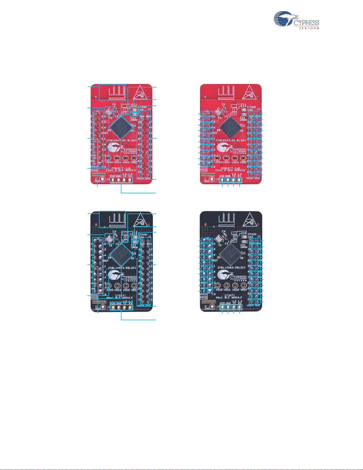
Figure 1-3 shows a markup of the onboard components, where red BLE module denotes the PSoC 4
BLE module and black BLE module denotes the PRoC BLE module.
Figure 1-3. BLE Module Markup
12 CY8CKIT-042-BLE Bluetooth® Low Energy (BLE) Pioneer Kit Guide, Doc. # 001-93731 Rev. **
Page 13
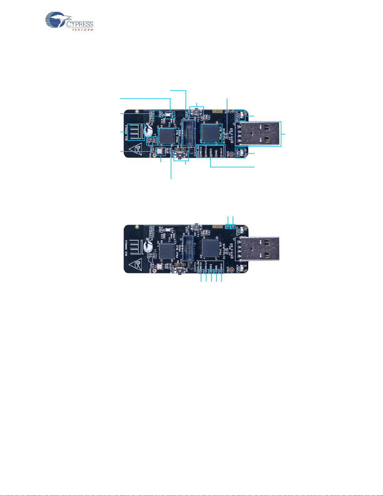
The Dongle board consists of the blocks shown in Figure 1-4.
13P$#-&
SFTFUCVUUPO
$:#--29*
13P$#-&EFWJDF
14P$-1
QSPHSBNNJOHUFTUQPJOUT
$:$-5*-1
14P$-1QSPHSBNNFS
BOEEFCVHHFS
6TFSCVUUPO
1PXFS-&%
64#QMVH
4UBUVT-&%
8JHHMF
BOUFOOB
"OUFOOB
NBUDIJOH
OFUXPSL
"./
.)[DSZTUBM
6TFS-&%
13P$FYUFSOBMQSPHSBNNJOHIFBEFS
,)[
DSZTUBM
CPUUPNTJEF
48%*0
48%$-,
93&4
(/%
7#64
1@
1@
Figure 1-4. BLE Dongle Markup
Introduction
1.3 PSoC Creator™
PSoC Creator is a state-of-the-art, easy-to-use integrated design environment (IDE). It introduces
revolutionary hardware and software co-design, powered by a library of preverified and
precharacterized PSoC Components™.
With PSoC Creator, you can:
■ Drag and drop PSoC Components to build a schematic of your custom design
■ Automatically place and route components and configure GPIOs
■ Develop and debug firmware using the included component APIs
PSoC Creator also enables you to tap into an entire tool e cosystem wit h integrate d compiler ch ains
and production programmers for PSoC devices.
For more information, visit www.cypress.com/psoccreator.
CY8CKIT-042-BLE Bluetooth® Low Energy (BLE) Pioneer Kit Guide, Doc. # 001-93731 Rev. ** 13
Page 14

Introduction
1.4 Getting Started
This guide will help you get acquainted with the BLE Pioneer Kit:
■ The Software Installation chapter on page 19 describes the installation of the kit software. This
includes the PSoC Creator IDE for development and debu gging applications, PSoC Programmer
for programming hex files, and the CySmart PC Tool for BLE host emulation.
■ The Kit Operation chapter on page 23 describes the major features of the BLE Pioneer Kit and
functionalities such as programming, debugging the USB-UART and USB-I
■ The Example Projects chapter on page 37 describes multiple PSoC 4 BLE and PRoC BLE code
examples that will help you understand how to create your own BLE application using the BLE
component and device.
■ The Hardware chapter on page 83 details the hardware content of the kit and the hardware
operation.
■ The Advanced Topics chapter on page 113 explains the functionality of some features of the kit,
such as the USB-UART bridge, USB-I
■ The Appendix on page 167 provides schematics, board layouts, and the bill of materials (BOM).
2
C bridge, F-RAM, iOS app, and CySmart PC Tool.
1.5 Additional Learning Resources
Visit www.cypress.com/go/psoc4ble and www.cypress.com/procble for additional learning resources
in the form of datasheets, technical reference manuals, and application notes.
2
C bridges.
Visit www.cypress.com/go/cysmart for information on the CySmart PC tool.
1.5.1 Beginner Resources
PSoC Creator Traini ng: www.cypress.com/go/creatorstart/creatortraining
1.5.2 Application Notes
Visit www.cypress.com/appnotes to view a growing list of application notes for PSoC 3, PSoC 4,
PSoC 4 BLE, PRoC BLE, and PSoC 5LP.
14 CY8CKIT-042-BLE Bluetooth® Low Energy (BLE) Pioneer Kit Guide, Doc. # 001-93731 Rev. **
Page 15

1.5.3 PSoC Creator Example Projects
These simple example projects demonstrate how to configure and use PSoC Creator co mponents.
To open an example proje ct in PSoC Creator, go to File > Example Project (see Figure 1-5) and
choose the required example project.
Figure 1-5. PSoC Creator Example Projects
Introduction
1.5.4 Component Datasheets
Right-click a component and select Open Datasheet (see Figure 1-6). Visit this page for the BLE
component datasheet.
Figure 1-6. Opening Component Datasheet
1.5.5 Bluetooth Learning Resources
The Bluetooth Developer Portal provides material by the Special Interest Group (SIG) for learning
various aspects of the Bluetooth Low Energy protocol and systems. Some of them are:
■ Training videos
■ GATT profiles
■ Bluetooth community forum
1.5.6 Learning From Peers
Cypress Developer Community Forums: Visit www.cypress.com/forums
CY8CKIT-042-BLE Bluetooth® Low Energy (BLE) Pioneer Kit Guide, Doc. # 001-93731 Rev. ** 15
Page 16

Introduction
1.5.7 Other Related Resources
■ Digilent PMod: www.digilentinc.com/pmods/
■ Arduino: http://arduino.cc/en/Main/ArduinoBoardUno
1.6 Technical Support
For assistance, go to our support web page, www.cypress.com/support, or contact our customer
support at +1 (800) 541-4736 Ext. 2 (in the USA) or +1 (408) 943-2600 Ext. 2 (International).
1.7 Documentation Convent i ons
Table 1-1. Document Conventions for Guides
Convention Usage
Courier New
Italics
[Bracketed, Bold]
File > Open
Bold
Times New Roman
Text in gray boxes Describes cautions or unique functionality of the product.
Displays file locations, user entered text, and source code:
C:\...cd\icc\
Displays file names and reference documentation:
Read about the sourcefile.hex file in the PSoC Creator User Guide.
Displays keyboard commands in procedures:
[Enter] or [Ctrl] [C]
Represents menu paths:
File > Open > New Project
Displays commands, menu paths, and icon names in procedures:
Click the File icon and then click Open.
Displays an equation:
2 + 2 = 4
16 CY8CKIT-042-BLE Bluetooth® Low Energy (BLE) Pioneer Kit Guide, Doc. # 001-93731 Rev. **
Page 17

1.8 Acronyms
Table 1-2. Acronyms Used in this Document
Acronym Definition
ADC Analog-to-Digital Converter
API Application Programming Interface
BLE Bluetooth Low Energy
CD Compact Disc
CDC Communications Device Class
COM Communication Port
DVD Digital Video Disc
ESD Electrostatic Discharge
F-RAM Ferroelectric Random Access Memory
GUI Graphical User Interface
GPIO General Purpose Input/Output
I2C Inter-Integrated Circuit
IAS Immediate Alert Service
IDAC Interconnecting Digital-Analog Converter
IDE Integrated Development Environment
ISO International Organization for Standardization
LDO Low Drop Out (voltage regulator)
LED Light-Emitting Diode
LP Low Power
LPT Line Print Terminal
PrISM Precise Illumination Signal Modulation
PRoC Programmable Radio-on-Chip
PRM Protocol Service Multiplexer
PSoC Programmable Systems-on-Chip
PWM Pulse-Width Modulation
QFN Quad Flat No-lead (package)
RGB Red Green Blue
SAR Successi ve Approximation Register
SPI Serial Peripheral Interface
SWD Serial Wire Debug
UART Universal Asynchronous Receiver Transmitter
USB Universal Serial Bus
USB CDC Universal Serial Bus Communications Device Class
Introduction
CY8CKIT-042-BLE Bluetooth® Low Energy (BLE) Pioneer Kit Guide, Doc. # 001-93731 Rev. ** 17
Page 18

Introduction
18 CY8CKIT-042-BLE Bluetooth® Low Energy (BLE) Pioneer Kit Guide, Doc. # 001-93731 Rev. **
Page 19

2. Software Installation
This chapter describes the steps to install the software tools and packages on a PC for using the
BLE Pioneer Kit. This includes the IDE on which the projects will be built and used for programming.
2.1 Before You Begin
All Cypress software installations require administrator privileges. However, this is not the case for
installed software. Before you install the kit software, close any other Cypress software that is
currently running.
2.2 Install Software
Follow these steps to install the BLE Pioneer Kit software:
1. Download the BLE Pioneer Kit software from www.cypress.com/CY8CKIT-042-BLE. The kit
software is available in the following formats:
a. CY8CKIT-042-BLE Kit Setup: This installation package contains the files related to the kit.
However, it does not include the Windows Installer or Microsoft .NET framework packages. If
these packages are not on your computer, the installer directs you to download and install
them from the Internet.
b. CY8CKIT-042-BLE Kit Only: This executable file installs only the kit contents, which include kit
code examples, hardware files, and user documents. This package can be used if all the
software prerequisites (listed in step 5) are installed on your PC.
c. CY8CKIT-042-BLE DVD ISO: This file is a complete package, stored in a DVD-ROM image
format, that you can use to create a DVD or extract using an ISO extraction program such as
WinZip or WinRAR. The file can also be mounted similar to a virtual CD/DVD using virtual
drive programs such as ‘Virtual CloneDrive’ and ‘MagicISO’. This file includes all the required
software, utilities, drivers, hardware files, and user documents.
2. If you have downloaded the ISO file, mount it on a virtual drive; if you do not have a virtual drive
to mount, extract the ISO contents. Double-click cyautorun.exe in the root directory of the
extracted content or mounted ISO if “Autorun from CD/DVD” is not enabled on the PC. The
installation window will appear automatically.
Note: If you are using the “Kit Setup” or “Kit Only” file, then go to step 4 for installation.
CY8CKIT-042-BLE Bluetooth® Low Energy (BLE) Pioneer Kit Guide, Doc. # 001-93731 Rev. ** 19
Page 20

Software Installation
3. Click Install CY8CKIT-042-BLE Kit to start the kit installation, as shown in Figure 2-1.
Figure 2-1. Kit Installer Screen
4. Select the folder in which you want to install the CY8CKIT-042-BLE kit-related files. Choose the
directory and click Next.
5. When you click Next, the CY8CKIT-042-BLE Kit installer automatically installs the required
software, if it is not present on your computer. Following are the required software:
Note: Incase of Setup Only installer package, please download and install below prerequisites.
a. PSoC Creator 3.1 or later: Download the latest version from www.cypress.com/psoccreator.
b. PSoC Programmer 3.21.1 or later: This is installed as part of PSoC Creator installation
(www.cypress.com/programmer).
c. CySmart 1.0 or later: Download the latest version from www.cypress.com/go/cysmart.
20 CY8CKIT-042-BLE Bluetooth® Low Energy (BLE) Pioneer Kit Guide, Doc. # 001-93731 Rev. **
Page 21

Software Installation
6. Choose the Typical/Custom/Complete installation type in the Product Installation Overview
window, as shown in Figure 2-2. Click Next after you select the installation type.
Figure 2-2. Product Installation Overview
7. Read the license agreement and select I accept the terms in the license agreement to
continue with installation. Click Next.
8. When the installation begins, a list of packages appears on the installation page. A green check
mark appears next to each package after successful installation.
9. Click Finish to complete the CY8CKIT-042-BLE kit installation.
10.Enter your contact information or select the check box Continue Without Contact Information.
Click Finish to complete the CY8CKIT-042-BLE kit installation.
11.After the installation is complete, the kit contents are available at the following location:
<Install_Directory>\CY8CKIT-042-BLE Kit
Default location:
Windows 7 (64-bit): C:\Program Files (x86)\Cypress\CY8CKIT-042-BLE Kit
Windows 7 (32-bit): C:\Program Files\Cypress\CY8CKIT-042-BLE Kit
Note: For Windows 7/8/8.1 users, the installed files and the folder are read only. To use the installer
example project, follow the steps outlined in the Example Projects chapter on page 37.
The kit installer also installs the CySmart PC Tool for PC. This software, along with the Dongle,
allows the PC to emulate as a BLE central device. Refer to CySmart PC Tool on page 158 for more
details on how to use the CySmart PC Tool.
CY8CKIT-042-BLE Bluetooth® Low Energy (BLE) Pioneer Kit Guide, Doc. # 001-93731 Rev. ** 21
Page 22

Software Installation
2.3 Uninstall Software
The software can be uninstalled using one of the following methods:
■ Go to Start > All Programs > Cypress > Cypress Update Manager > Cypress Update
Manager; select the Uninstall button.
■ Go to Start > Control Panel > Programs and Features for Windows 7 or Add/Remove
Programs for Windows XP; select the Uninstall/Change button.
22 CY8CKIT-042-BLE Bluetooth® Low Energy (BLE) Pioneer Kit Guide, Doc. # 001-93731 Rev. **
Page 23

3. Kit Operation
Status LED
Green
BLE/Arduino Compatible Headers
Proximity wire
connector
CapSense Slider
5 Segment
Reset SW
(Push Button)
USB
Mini B
PSoC 5LP
Programmer/Serial
Communication
PSoC 5LP
10 pin Prog. header
PSoC 5LP I/Os
16 pin Expansion header
PMOD header
6 pin PMOD header
ESD
Protection
MOSFET
Protection ckt
LDO
ORing
Diodes
BLE/Arduino Compatible Headers
Jumper
BLE current measuring
Coin cell
Battery holder
Power
LED Red
BLE Module I/Os
20 pin header
FRAM
I2C pull-up
via FET
ORing
Diodes
User SW
(Push Button)
BLE Module I/Os
24 pin header
VIN
VBUS
VCC
D+ / D-
VDD
BLE Reset
3.3V
~3V
SWD
I2C / SPI / UART
I2C
Voltage Ctrl
3 pin Jumper
RGB LED
MOSFET
Protection ckt
BLE SWD
10 pin Prog. header
PRoC BLE/
PSoC 4 BLE
This chapter introduces you to the BLE Pioneer kit and the features that will be used as part of the kit
operation. These primarily include USB connection, programming/debugging, and programmer firm-
ware update. The chapter also describes the USB-UART and USB-I
tools that can be used to communicate with the BLE device on the kit.
3.1 Theory of Operation
Figure 3-1, Figure 3-2, and Figure 3-3 show the block diagrams for the BLE Pioneer Baseboard,
BLE Module board, and Dongle.
Figure 3-1. BLE Pioneer Baseboard Block Diagram
2
C bridges along with the PC
The BLE Pioneer board acts as the baseboard for the PSoC 4 BLE (red module) and PRoC BLE
(black module), which can be connected to the BLE Pioneer board. The Pioneer board contains a
CY8CKIT-042-BLE Bluetooth® Low Energy (BLE) Pioneer Kit Guide, Doc. # 001-93731 Rev. ** 23
PSoC 5LP that is used as an onboard programmer or debugger, and for the USB-Serial interface.
The Baseboard is Arduino form factor compatible, enabling Arduino shields to be connected on top
of the board to extend the functionality of BLE modules. The board also features a 1-Mb F-RAM, an
RGB LED, a five-segment CapSense slider, a proximity header, a user switch, and a reset switch for
the PSoC 4 BLE and PRoC BLE devices on the module. The Pioneer board supports three voltage
levels: 1.9 V, 3.3 V, and 5 V.
The baseboard can also be used as a standalone programmer to program and debug other
PSoC 4 BLE/PRoC BLE devices using serial wire debug (SWD), and as a USB-Serial bridge. The
firmware on PSoC 5LP device enables bootloading over USB to upgrade the firmware.
Page 24

Kit Operation
PRoC BLE/
PSoC 4
BLE
BLE I/Os
20 pin Header (Digital, Power and Ground Pins)
GPIO
GPIO
KHz
Crystal
Decaps
CMOD
SAR
Bypass Cap
CTANK
VREF
Power
RF
matching
MHz
Crystal
Test
points
4 pin
header
RX/ TX/ Gnd
BLE I/Os
24 pin Header (Analog, Power and Ground Pins)
Ferrite Bead
VDDD/A/R
Power
Power
Decaps
MATCHING
CIRCUIT
PSoC 5LP
68QFN
I2C
UART
SWD
SPI
USB
2.0
Type-A
Plug
10-Pin Programming
Header
SWD
USER Button
USER LED
XRES Button
XRES
RF
Test Points
Protection
Circuits
D+ / D-
STATUS LED
POWER LED
EXTRA GPIO
CRYSTALS
PRoC BLE
56QFN
Power
Figure 3-2. BLE Module Block Diagram
This kit includes two modules boards. These boards act as a basic breakout board for the
CY8C4247LQI-BL483 and CYBL10563-56LQXI BLE silicon. The PSoC 4 BLE and PRoC BLE
Modules are identical except for the silicon. In addition to including the PSoC 4 BLE and PRoC BLE
devices, the module boards also contain the BLE passives (resistors, capacitors, external crystals,
and antenna-matching network), an onboard antenn a, and headers for conn ecting to the Baseboard.
The Dongle is the host's wireless interface for the BLE device or project on the baseboard. The
dongle has a PRoC BLE device, configurable over various interfaces to work as expected for any
project. It also contains a PSoC 5LP, to be used as an onboard pr ogrammer or de bugger, and for the
USB-Serial interface, as shown in Figure 3-3.
The Dongle has a USB A-type plug to connect the PSoC 5LP to the USB port of the host PC. The
PSoC 5LP then communicates with the PRoC BLE device over UART or multiplexed I
2
C or an SPI
bus. The board also features a user LED, a user switch, and a reset switch for the PRoC BLE
device. The Dongle is powered directly through the USB port (VBUS) at 5.0 V.
The Dongle can also be used as a standalone programmer to program and debug other PSoC
devices (outside the dongle board) using SWD, and as a USB-Serial bridge after removing the
resistor between the SWD pins of PSoC 5LP and PRoC BLE.
Figure 3-3. BLE Dongle Block Diagram
24 CY8CKIT-042-BLE Bluetooth® Low Energy (BLE) Pioneer Kit Guide, Doc. # 001-93731 Rev. **
Page 25

3.2 BLE Pioneer Kit USB Connection
The BLE Pioneer kit connects to a PC over the USB interface (J13) and derives power from it. The
kit enumerates as a composite device, as shown in Table 3-1.
Note: Ensure that you install the kit installer on the system for successful enumeration. To download
and install the BLE Pioneer Kit, visit www.cypress.com/go/CY8CKIT-042-BLE.
Table 3-1. BLE Pioneer Kit Enumerated Interfaces
Port Description
USB Composite Device Composite device
KitProg Programmer and debugger
KitProg USB-UART USB-UART bridge, which will appear as a COM# port
USB Input Device
Figure 3-4. KitProg Driver Installation (appearance may differ depending on Windows platform)
USB-I
2
C bridge
Kit Operation
3.3 Placing Modules on Baseboard
To connect the BLE Modules (PSoC 4 BLE or PRoC BLE) on the Baseboard, place the BLE Module
over the headers J10 and J11 while keeping the antenna on the module directing outside the
baseboard and press it. Note that the two parallel headers J10 and J11 are not equal (24-pin and
20-pin, respectively) and will not allow the BLE Module to be inserted in the opposite direction.
Figure 3-5. Baseboard with J10 and J11 Headers to connect BLE Modules
CY8CKIT-042-BLE Bluetooth® Low Energy (BLE) Pioneer Kit Guide, Doc. # 001-93731 Rev. ** 25
Page 26

Kit Operation
To remove the BLE Modules from the BLE Pioneer kit, hold the BLE Pioneer kit in one hand and the
BLE Module in the other, as shown in Figure 3-6, and pull it out in a rocking motion.
Figure 3-6. Remove BLE Module Connected on BLE Pioneer Kit
3.4 Programming and Debugging BLE Device
The kit can be programmed and debugged using the onboard PSoC 5LP programmer and
debugger. Before programming the device, ensure that PSoC Creator and PSoC Programmer are
installed on the PC. See the section Install Software on page 19 for more information.
1. To program the device, plug the USB cable into the programming USB connector, J13, as shown
in Figure 3-7. The kit will enumerate as a composite device.
Figure 3-7. Connect USB Cable to J13
26 CY8CKIT-042-BLE Bluetooth® Low Energy (BLE) Pioneer Kit Guide, Doc. # 001-93731 Rev. **
Page 27

Kit Operation
Mini USB PSoC 5LP
PSoC 4 BLE/
PRoC BLE
SWDCLK
Reset
SWDIO
D+
D-
2. The onboard PSoC 5LP uses SWD to program the PSoC 4 BLE or PRoC BLE device. See
Figure 3-8 for this implementation.
Figure 3-8. SWD Programming PSoC 4 BLE/PRoC BLE using PSoC 5LP
3. To load the desired example project, open PSoC Creator and go to
Workspace
4. Build the project by choosing
. This will provide the option to browse to and open your saved project.
Build > Build <Project Name> or [Shift] [F6], as shown in
Figure 3-9.
Figure 3-9. Build an Example Project
File > Open > Project/
CY8CKIT-042-BLE Bluetooth® Low Energy (BLE) Pioneer Kit Guide, Doc. # 001-93731 Rev. ** 27
Page 28

Kit Operation
5. If there are no errors during build, program the firmware into the kit by choosing Debug >
Program
BLE Pioneer Kit and the kit will be ready f or use. For example, if the
or pressing [Ctrl] [F5], as shown in Figure 3-10. This will program the device on the
PSoC_4_BLE_Kit_Test
project is programmed successfully to the PSoC 4 BLE Module on the BLE Pioneer kit, then you
will observe the blue LED toggling every second. If debugging is needed on the project, go to
step 6.
Figure 3-10. Programming Device From PSoC Creator
6. To debug the project using PSoC Creator, choose
Debug > Debug or press [F5].
7. When the project is built and programmed into the device on the BLE Pioneer Kit, PSoC Creator
will enter the Debug mode; you can use it to debug your application. For more details on using
the debug features, see the Cypress application note Getting Started with PSoC 4 BLE.
28 CY8CKIT-042-BLE Bluetooth® Low Energy (BLE) Pioneer Kit Guide, Doc. # 001-93731 Rev. **
Page 29

3.5 Dongle Connection
The Dongle, shown in Figure 3-11, provides the BLE Central device capability using the CySmart PC
Tool (see CySmart PC Tool on page 158) on the PC. It helps in connecting and validating the
example projects loaded on the BLE Pioneer Kit (Baseboard with one of the modules) through BLE.
The CySmart PC Tool on the PC is the interface with which to configure the Dongle and analyze the
BLE data transferred after connection with a BLE peripheral.
Figure 3-11. Dongle
Kit Operation
After being connected to the PC through a USB port, the Dongle enumerates as a composite device,
similar to the BLE Pioneer Kit. When enumerated, it allows similar features, such as programming/
debugging of the onboard PRoC BLE, USB-UART bridge, and USB-I
interface is used to communicate with the CySmart PC Tool and emulate a BLE central device on
PRoC BLE.
2
C bridge. Additionally, the
CY8CKIT-042-BLE Bluetooth® Low Energy (BLE) Pioneer Kit Guide, Doc. # 001-93731 Rev. ** 29
Page 30
Kit Operation
The Dongle works along with the CySmart PC Tool, as shown in Figure 3-12. The CySmart PC Tool
is installed as part of the BLE Pioneer Kit in st allation. The CySmart PC Tool op eration is e xplained i n
CySmart PC Tool on page 158.
Figure 3-12. Dongle Interface on CySmart PC Tool
In case the Dongle contains custom firmware on PRoC BLE, the original CySmart firmware can be
programmed back to the Dongle to restore the Dongle functionality. Follow these steps to do the
same:
1. Connect the Dongle to the USB port on the PC.
2. Open PSoC Programmer 3.21.1 by going to
PSoC Programmer 3.21.1
> PSoC Programmer 3.21.1.
Start > All Programs > Cypress >
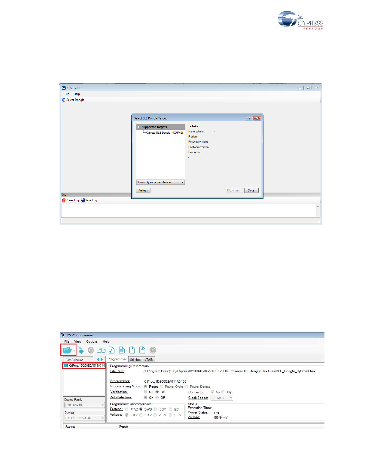
3. When PSoC Programmer opens, it will automatically detect the KitProg on the Dongle. Click the
File Load button and browse to the location of the BLE_Dongle_CySmart.hex file. The hex file is
located at:
C:\Program Files (x86)\Cypress\
CY8CKIT-042-BLE Kit\<version>\Firmware\BLE Dongle\Hex Files\
Figure 3-13. Open Hex File
30 CY8CKIT-042-BLE Bluetooth® Low Energy (BLE) Pioneer Kit Guide, Doc. # 001-93731 Rev. **
Page 31

Kit Operation
4. Ensure the other setting match as shown in Figure 3-13. Click the Program button to start
programming. The status bar at the bottom of the PSoC Programmer window will show the
programming status and the result (Successful/Failed).
Figure 3-14. Programming Hex File to Dongle
5. After programming is completed successfully, the Dongle firmware is updated and can be used to
connect to the CySmart PC tool.
3.6 USB-UART Bridge
The onboard PSoC 5LP on both the Baseboard and Dongle also acts as a USB-UART bridge to
transfer and receive data from the PSoC 4 BLE or PRoC BLE device to the PC via the COM terminal
software. When the USB mini-B cable is connected to J13 of the Baseboard or the Dongle is
connected to the PC, a device named
in the Device Manager . For mor e det ails about th e USB-UART functionality, see Using PSoC 5LP as
USB-UART Bridge on page 113.
To use the USB-UART functionality in the COM terminal software, select the corresponding COM
port as the communication port for transferring data to and from the COM terminal software.
For both the Baseboard and the Dongle, the UART lines are hardwired onboard between the PSoC
5LP and BLE Modules. No ext ernal UART connection between the two devices is needed. Simply
place the UART component in the PSoC 4 BLE or PRoC BLE and assign the UART pins a s shown in
Table 3-2.
Table 3-2. UART Pin Assignment in BLE Devices for USB-UART Bridge
Pin BLE Pioneer Kit BLE Dongle
UART_RX P1_4 P1_4
UART_TX P1_5 P1_5
“KitProg USB-UART” is available under Ports (COM & LPT)
CY8CKIT-042-BLE Bluetooth® Low Energy (BLE) Pioneer Kit Guide, Doc. # 001-93731 Rev. ** 31
Page 32

Kit Operation
Table 3-3 lists the specifications supported by the USB-UART bridge.
Table 3-3. Specifications Supported by USB-UART Bridge
Parameter Supported Values
Baud Rate 1200, 2400, 4800, 9600, 19200, 38400, 57600, and 115200
Data Bits 8
Parity None
Stop Bits 1
Flow Control None
File Transfer Protocols sup-
ported
3.7 USB-I2C Bridge
The PSoC 5LP also functions as a USB-I2C bridge. In this role, PSoC 5LP communicates with
PSoC 4 BLE/PRoC BLE using an I
software utility running on the PC, called the
for both the BLE Pioneer Kit and the Dongle.
Xmodem, 1K Xmodem, Ymodem, Kermit, and Zmodem (only
speeds greater than 2400 baud)
2
C interface, and sends that data over the USB to the USB-I2C
Bridge Control Panel (BCP). This feature is available
The BCP is available as part of the PSoC Programmer installation. This software can be used to
send and receive USB-I
header J13 on the BLE Pioneer Kit or when the Dongle is connected to the PC, the
2
C is available under Connected I2C/SPI/RX8 Ports in the BCP, as shown in Figure 3-15.
I
To open BCP in your system, go to
2
C data from the PSoC 5LP. When the USB mini-B cable is connected to
KitProg USB-
Start > All Programs > Cypress > Bridge Control Panel.
Figure 3-15. Bridge Control Panel
32 CY8CKIT-042-BLE Bluetooth® Low Energy (BLE) Pioneer Kit Guide, Doc. # 001-93731 Rev. **
Page 33

Kit Operation
To use the USB-I2C functionality, select the KitProg USB-I2C in the BCP. On successful connection,
the
Connected and Powered tabs turn green, as shown in Figure 3-16.
2
Figure 3-16. KitProg USB-I
C Connected in Bridge Control Panel
2
USB-I
C is implemented using the USB and I2C components of PSoC 5LP. For the BLE Pioneer Kit,
the SCL (P12_0) and SDA (P12_1) lines from the PSoC 5LP are connected to the SCL (P3_5) and
SDA (P3_4) lines of the BLE Module header. For the Dongle, the SCL (P12_0) and SDA (P12_1)
lines from the PSoC 5LP are connected to the SCL (P3_5) and SDA (P3_4) lines. The
2
USB-I
See Using PSoC 5LP as USB-I2C Bridge on page 124 for building a project that uses the USB-I
C bridge currently supports I2C speed of 50 kHz, 100 kHz, 400 kHz, and 1 MHz.
2
bridge functionality.
C
CY8CKIT-042-BLE Bluetooth® Low Energy (BLE) Pioneer Kit Guide, Doc. # 001-93731 Rev. ** 33
Page 34

Kit Operation
3.8 Updating the Onboard Programmer Firmware
The BLE Pioneer kit and Dongle contains the modified KitProg that is required to reliably use the
BLE Pioneer kit's functionality. Do not update the KitProg firmware on PSoC 5LP on this kit. If the
KitProg has been updated with the firmware provided with PSoC Programmer, then you can restore
the original KitProg for this kit using the Bootloader Host tool. The required CYACD file is present in
the installed location of the ki t:
<Install_Directory>\CY8CKIT-042-BLE Kit\<version>\Firmware\Programmer\KitProg
\KitProg.cyacd
Follow the steps in the Advanced Topics chapter on page 113 to restore the KitProg using the Boot-
loader Host tool.
3.9 Measure Coin-cell Power Consumption
To measure the power consump tion of a project with coin-cell bat tery, connect the coin-cell battery
directly to the BLE Modules as shown in the Figure 3-17. The baseboard is designed with additional
circuits to protect the PSoC 4 BLE/PRoC BLE device and the F-RAM in Arduino environment. Note
that the power consumption measurements on the baseboard will also include the power consumed
by these additional circuits.
After you have programmed your application on the CY8CKIT-142 PSoC
CY5671 PRoC™ BLE Module, remove the BLE Module from the baseboard and connect the coincell battery (Figure 3-17). This setup enables an accurate power consumption measurement for the
application. The other pins on the BLE Module can be used to build the desired application.
®
4 BLE Module or the
Connect the positive terminal of the coin cell to pin J2.2 and negative terminal to pin J2.4 using
wires.
Figure 3-17. Powering the BLE Module using a Coin-Cell Battery
34 CY8CKIT-042-BLE Bluetooth® Low Energy (BLE) Pioneer Kit Guide, Doc. # 001-93731 Rev. **
Page 35

Kit Operation
Connect an ammeter in series with the battery to measure the power consumption as shown in
Figure 3-18.
Figure 3-18. Current Measurement of BLE Module when Powered from a Coin-cell Battery
CY8CKIT-042-BLE Bluetooth® Low Energy (BLE) Pioneer Kit Guide, Doc. # 001-93731 Rev. ** 35
Page 36

Kit Operation
36 CY8CKIT-042-BLE Bluetooth® Low Energy (BLE) Pioneer Kit Guide, Doc. # 001-93731 Rev. **
Page 37

4. Example Projects
This chapter demonstrates the functionality of the PSoC 4 BLE and PRoC BLE devices using the
BLE Pioneer kit-based example projects. To access these example projects, download and install
the kit setup file from the kit web page. The example projects are available in the firmware folder in
the installation location.
The Cypress BLE device comes in two variants:
■ PSoC 4 BLE: The PSoC 4 BLE product family is the new wireless member of the PSoC 4
architecture platform. The family provides a full programmable analog and digital system and a
complete schematic view of PSoC Creator. The PSoC 4 BLE family provides a 32-bit ARM
Cortex-M0 based MCU subsystem with programmable analog and digital peripherals, such as
universal digital blocks (UDBs), 12-bit SAR ADC, Op-amp, LP comparator, IDACs, UART, I
SPI, and timer/counter/PWM block. It also has a dedicated CapSense block (in select part
numbers) to implement the touch-sensing solution, with a practical system SNR of 100:1.
■ PRoC BLE: This family provides prebuilt part numbers for applications such as human interface
devices (HID), remote control, trackpad, and toys. PRoC BLE also supports up to two-finger
gestures for trackpad and remote control applications. The PRoC BLE product family enriches
PRoC wireless capacitive touch devices with the Bluetooth Low Energy protocol. The PRoC BLE
family has embedded gestures (in select part numbers) to implement the touch-sensing solution
for trackpad implementation. It also provides a 32-bit ARM Cortex-M0 based MCU subsystem
with analog and digital peripherals, such as 12-bit SAR ADC, UART, I
counter/PWM blocks. The family uses a special PSoC Creator schematic view for easy
configuration of PRoC BLE devices.
2
C, PWMs, and timer/
2
C,
The example projects that are part of this kit installer include projects for both these devices. Unless
otherwise indicated, the functionality of the example projects is the same for PSoC 4 BLE and
PRoC BLE. The mode of use and the PSoC Creator schematic view will vary slightly for each
device.
4.1 Using Example Projects
Follow these steps to open and use the example projects:
1. Launch PSoC Creator from
Creator 3.1
CY8CKIT-042-BLE Bluetooth® Low Energy (BLE) Pioneer Kit Guide, Doc. # 001-93731 Rev. ** 37
.
Start > All Programs > Cypress > PSoC Creator 3.1 > PSoC
Page 38

Example Projects
2. On the Start Page, choose Examples and Kits > Kits > CY8CKIT-042-BLE. A list of example
3. Click on the desired example project.
Figure 4-1. Open Example Project from PSoC Creator
projects appears, as shown in Figure 4-1. Projects named with the prefix '
PSoC_4_BLE_' work
on the BLE Pioneer kit with the PSoC 4 BLE Module; projects named with the prefix
'
PRoC_BLE_' work on the BLE Pioneer kit with the PRoC BLE Module.
4. Select the folder where you want to save the project and click
38 CY8CKIT-042-BLE Bluetooth® Low Energy (BLE) Pioneer Kit Guide, Doc. # 001-93731 Rev. **
OK.
Page 39

Example Projects
5. BLE projects use a public device address set in the BLE component GUI to advertise and scan,
depending on the role: peripheral or central mode. If there are other kits in close proximity, which
have the same public device address, then wrong devices may be connected or connections can
fail. To prevent this, you can change the
in the BLE component. To do this, double-click the BLE component in TopDesign, go to the
Settings
tab, and choose the General setting. Add the desired public device address (non-zero)
and device name in the respective fields, as shown in Figure 4-2. Click
Public device address (and preferably Device name)
GAP
OK.
Figure 4-2. Change BLE Public Device Address and Name
6. Build the example project by choosing
Build > Build <Project Name>, as shown in Figure 4-3. A
hex file will be generated.
Figure 4-3. Build Project from PSoC Creator
CY8CKIT-042-BLE Bluetooth® Low Energy (BLE) Pioneer Kit Guide, Doc. # 001-93731 Rev. ** 39
Page 40

Example Projects
7. To program the kit with this example project, connect the Baseboard to the PC by plugging it into
8. Choose
Figure 4-4. Program Device in PSoC Creator
the USB mini-B connector (J13) on the baseboard, as described in BLE Pioneer Kit USB
Connection on page 25. Ensure that the correct BLE Module is placed on the baseboard,
depending on the project opened.
Debug > Program in PSoC Creator, as shown in Figure 4-4.
9. If the device is not yet acquired, PSoC Creator will open the programming window. Select
KitProg and click the Port Acquire button, as shown in Figure 4-5.
Note: The string following the 'KitProg' is the serial ID for the programmer on the kit. Each kit will
have their unique serial ID. If various kits are connected to the same system, the serial ID can be
used to select the correct kit to program the firmware. Additionally, the serial ID starting with 'BLE'
belongs to the Dongle (see Dongle Connection on page 29) and provides visual confirmat ion for
Dongles connected to the system.
Figure 4-5. Port Acquire
40 CY8CKIT-042-BLE Bluetooth® Low Energy (BLE) Pioneer Kit Guide, Doc. # 001-93731 Rev. **
Page 41

Example Projects
10.After the device is acquired, it is shown in a tree structure below the KitProg. Click the Connect
button and then OK to exit the window and start programming, as shown in Figure 4-6.
Figure 4-6. Connect Device From PSoC Creator and Program
Note: As stated previously, the BLE Pioneer Kit supports both Cypress BLE devices: PSoC 4 BLE
and PRoC BLE. Thus, there are two v ersions of eac h of the kit example projects demonstrating the
same functionality. Projects named with the prefix 'PSoC_4_BLE_' work with the PSoC 4 BLE
Module placed on the Baseboard. Projects named with the prefix ‘PRoC_BLE_’ work with the PRoC
BLE Module placed on the Baseboard. Ensure that the correct module is placed on the Baseboard
before programming the device with the corresponding kit example projects.
The description, hardware configurations, and verification method of the kit example projects
explained in the following sections are valid for both PSoC 4 BLE and PRoC BLE devices. Unless
explicitly mentioned, the theory and usability for these example projects should be considered same
for both the modules/devices.
This document refers to the BLE Pioneer kits, Dongle, and PC/Mobile as BLE central or peripheral
devices. A BLE central device is normally the master and requests/commands data from peripheral
device. BLE-enabled phones and PCs are one such example. BLE peripheral devices, on the other
hand, store the actual data and send it to central devices when requested. Examples include BLEenabled sensors, proximity beacons, and so on.
CY8CKIT-042-BLE Bluetooth® Low Energy (BLE) Pioneer Kit Guide, Doc. # 001-93731 Rev. ** 41
Page 42

Example Projects
4.2 Kit Test
4.2.1 Project Description
This example project is a non-BLE project that is meant to validate the BLE Pioneer Kit, if desired.
This example project verifies whether the onboard device is working properly. It uses one timer that
periodically generates an interrupt and causes toggling of the onboa rd LED (Figure 4-7).
Two projects demonstrate this functionality on two different devices:
■ PSoC_4_BLE_Kit_Test works with the PSoC 4 BLE Module.
■ PRoC_BLE_Kit_Test works with PRoC BLE Module.
Figure 4-7. TopDesign for PSoC_4_BLE_Kit_Test
42 CY8CKIT-042-BLE Bluetooth® Low Energy (BLE) Pioneer Kit Guide, Doc. # 001-93731 Rev. **
Page 43

Figure 4-8. Top Design for PRoC_BLE_Kit_Test
Example Projects
4.2.2 Hardware Connections
No specific hardware connections are required for this project because all connections are
hardwired on the board . On the Workspace Explorer, double-click
PRoC_BLE_Kit_Test.cydwr on the left and select the pins shown in Figure 4-9.
Ensure that the correct BLE Module is placed on the Baseboard corresponding to the project being
used. PSoC_4_BLE_Kit_Test works with the PSoC 4 BLE Module (red BLE Module) and
PRoC_BLE_Kit_Test works with the PRoC BLE Module (black BLE Module).
Table 4-1. Pin Assignment for Test Project
Pin Name Port Name
Blue_LED P3_7
Figure 4-9. Pin Selection for Test Project
PSoC_4_BLE_Kit_Test.cydwr/
CY8CKIT-042-BLE Bluetooth® Low Energy (BLE) Pioneer Kit Guide, Doc. # 001-93731 Rev. ** 43
Page 44

Example Projects
Power BLE Kit
Start timer and
Interrupt
Is the Interrupt
Flag Set?
Toggle the state of
onboard LED
Reset Interrupt
Flag
NO
YES
4.2.3 Flow Chart
Figure 4-10 shows the flow chart of code implemented in the main.c file.
Figure 4-10. Test Project Flow Chart
44 CY8CKIT-042-BLE Bluetooth® Low Energy (BLE) Pioneer Kit Guide, Doc. # 001-93731 Rev. **
Page 45

4.2.4 V erify Output
The project is intended to validate the kit operation. See Using Example Projects on page 37 for
steps to program the kit with the project. After powering the kit and successfully programming it with
the test project, the blue LED of the onboard RGB LED should periodically toggle (Figure 4-11).
Figure 4-11. Toggling LED on BLE Pioneer Kit with PSoC 4 BLE Module
Example Projects
Figure 4-12. Toggling LED on BLE Pioneer Kit with PRoC BLE Module
CY8CKIT-042-BLE Bluetooth® Low Energy (BLE) Pioneer Kit Guide, Doc. # 001-93731 Rev. ** 45
Page 46

Example Projects
4.3 CapSense Slider and LED
4.3.1 Project Description
This example project demonstrates bidirectional dat a transfer between a BLE central device ( Dongle
or CySmart App) and the kit working as a peripheral with the CapSense slider and RGB LED
functionalities. The example project allows advertisement, connection, and data transfer over a
custom BLE profile. It uses a CapSense component to read finger location on the CapSense slider
and sends the value to a connected BLE central device. The project receives RGB color and
intensity values from the BLE central device, which are then translated into the proper color and
intensity on the onboard RGB LED.
The project also supports placing the system into sleep in the event of advertising timeout or BLE
disconnection. The system then wakes up and resumes when the user button (
pressed.
This is the default firmware that comes in BLE Modules shipped with the kit.
Two projects demonstrate this functionality on two different devices:
■ PSoC_4_BLE_CapSense_Slider_LED works with the PSoC 4 BLE Module
■ PRoC_BLE_CapSense_Slider_LED works with the PRoC BLE Module.
The PSoC 4 BLE project implements RGB color and intensity control using the PRiSM component
whereas the PRoC BLE uses the software implement ation of the PRiSM mode.
SW2) on the kit is
Figure 4-13. TopDesign for PSoC_4_BLE_CapSense_Slider_LED Project
46 CY8CKIT-042-BLE Bluetooth® Low Energy (BLE) Pioneer Kit Guide, Doc. # 001-93731 Rev. **
Page 47

Figure 4-14. TopDesign for PRoC_BLE_CapSense_Slider_LED Project
Example Projects
CY8CKIT-042-BLE Bluetooth® Low Energy (BLE) Pioneer Kit Guide, Doc. # 001-93731 Rev. ** 47
Page 48

Example Projects
4.3.2 Hardware Connections
No specific hardware connections are required for this project because all connections are
hardwired on the board. Ensure that the correct BLE Module is placed on the Baseboard
corresponding to the project being used. PSoC_4_BLE_CapSense_Slider_LED works with the
PSoC 4 BLE Module. PRoC_BLE_CapSense_Slider_LED works with the PRoC BLE Module.
On the Workspace Explorer, double-click on
PSoC_4_BLE_CapSense_Slider_LED.cydwr/
PRoC_BLE_CapSense_Slider_LED.cydwr on the left, and select the pins shown in Figure 4-15.
Table 4-2. Pin Assignments for CapSense Slider and LED Project
Pin Name Port Name
CapSense CMOD P4_0
CapSense Slider 1 P2_1
CapSense Slider 2 P2_2
CapSense Slider 3 P2_3
CapSense Slider 4 P2_4
CapSense Slider 5 P2_5
BLUE P3_7
GREEN P3_6
RED P2_6
User_Button P2_7
Figure 4-15. Pin Selection for CapSense Slider and LED Project
48 CY8CKIT-042-BLE Bluetooth® Low Energy (BLE) Pioneer Kit Guide, Doc. # 001-93731 Rev. **
Page 49

4.3.3 Flow Chart
Start
Advertisement
CapSense Slider
Swipped?
Received RGB
LED Data ?
NO
BLE Connection
Still Present?
NO
Send finger position
over CapSense
custom service
YES
Extract Data and
change color/
brightness on LED
YES
YES
Connected to BLE
Central device?
YES
NO
Process BLE
Events
Notifications
Enabled?
YES
NO
Powe r BLE Ki t
Start BLE, Prism
and CapSense
Component
System in Sleep and
waiting for User button
press
Put system to
sleep
NO
Wakeup at User
button press INT
Advertisement
Time-out?
NO
YES
Figure 4-16 shows the flow chart of code implemented.
Figure 4-16. CapSense Slider and LED Project Flow Chart
Example Projects
CY8CKIT-042-BLE Bluetooth® Low Energy (BLE) Pioneer Kit Guide, Doc. # 001-93731 Rev. ** 49
Page 50

Example Projects
4.3.4 V erify Output
The project can be verified by two methods: one using the CySmart PC Tool and Dongle, and the
other using the CySmart iOS BLE app.
To install and use the CySmart PC Tool, see CySmart PC Tool on page 158.
To install and use the CySmart iOS app, see CySmart iOS Application on page 150.
4.3.4.1 CySmart PC Tool
To verify the CapSense and LED project using the CySmart PC tool, follow these steps:
Note: See CySmart PC Tool on page 158 to learn how to use the tool.
1. Connect the Dongle to one of the USB ports on the PC.
2. Start CySmart PC Tool on the PC by going to
CySmart
Select the Dongle and click
3. Place the desired BLE Module, either PSoC 4 BLE or PRoC BLE, on the BLE Pioneer kit,
depending on the project chosen.
4. Power the BLE Pioneer kit through the USB connector J13.
5. Program the BLE Pioneer kit with the CapSense and LED example projects. Follow steps in
Using Example Projects on page 37 to program the device.
6. After programming successfully, press the user button (
advertisement. Advertisement is indicated by a blinking red LED on the Baseboard.
7. Click
by the device name and Bluetooth address in the list. Th is should be sa me as the o ne co nfigu red
in the BLE component GUI.
. You will see a list of Dongles connected to it. If no Dongle is found, click Refresh.
Start Scan to see the list of available BLE peripheral devices. You can confirm your device
Start > All Programs > Cypress > CySmart 1.0 >
Connect.
SW2) on the BLE Pioneer Kit to start
50 CY8CKIT-042-BLE Bluetooth® Low Energy (BLE) Pioneer Kit Guide, Doc. # 001-93731 Rev. **
Page 51

Example Projects
8. After the available devices are listed, double-click the CapSense Slider and LED device to
connect or click
Stop Scan and then click Connect.
Figure 4-17. Connect to CapSense Slider and LED Periph eral
9. If the connection is successful, you will see another tab opening besides the
this tab and click
Discover All Attributes.
Figure 4-18. Discover All Attributes
Master tab. Go to
CY8CKIT-042-BLE Bluetooth® Low Energy (BLE) Pioneer Kit Guide, Doc. # 001-93731 Rev. ** 51
Page 52

Example Projects
10.When all the attributes are listed, locate the attribute with UUID value of 0xCAA2, which is the
Figure 4-19. Write to CapSense Slider Characteristic Descriptor
characteristic under
Configuration
CapSense Slider custom service. It will also have a Client Characteristic
descriptor (UUID 0x2902). The properties of the descriptor appear in the Attribute
Details window, as shown in Figure 4-19.
11. Enter '01:00' in the value field and click
Write Value. This enables the notifications on the
CapSense Slider characteristic. The notifications received are displayed in the Value field of the
CapSense Slider characteristic.
52 CY8CKIT-042-BLE Bluetooth® Low Energy (BLE) Pioneer Kit Guide, Doc. # 001-93731 Rev. **
Page 53

Example Projects
12.Swipe your finger on the CapSense slider on the BLE Pioneer kit, as shown in Figure 4-21 and
see the notification values in the CapSense Slider value field, as shown in Figure 4-20.
Figure 4-20. CapSense Slider notification received
Figure 4-21. CapSense Slider
13.Write '00:00' to the
Client Characteristic Configuration descriptor to disable notifications.
Figure 4-22. Disable Notifications
CY8CKIT-042-BLE Bluetooth® Low Energy (BLE) Pioneer Kit Guide, Doc. # 001-93731 Rev. ** 53
Page 54

Example Projects
14.Now, locate the UUID value of 0xCBB1, which is the RGB LED Control characteristic. On the
Figure 4-23. Read RGB LED Control Characteristic Value
right side under the Attribute Details tab, the read and write properties are enabled. Click the
Read value to read the existing 4-byte of onboard RGB LED color information, as shown in
Figure 4-23. The first three bytes have the color values Red, Green, an d Blue; the fourth byte is
the overall intensity value, all in the range 0 to 255.
15.Modify the four bytes of data in the
Value field and click Write value. You will see the
corresponding change in the color and intensity of the RGB LED on the BLE Pioneer kit, as
shown in Figure 4-24.
Note: In case the BLE Pioneer kit is powered from the coin cell and not the USB Vbus, then the
color mixing and intensity will vary. This is because the coin cell provides a lower driving voltage
for RGB LEDs.
Figure 4-24. Write RGB LED Control Characteristic Value
54 CY8CKIT-042-BLE Bluetooth® Low Energy (BLE) Pioneer Kit Guide, Doc. # 001-93731 Rev. **
Page 55

Figure 4-25. RGB LED Control with PSoC 4 BLE Module
Example Projects
Figure 4-26. RGB LED Control with PRoC BLE Module
CY8CKIT-042-BLE Bluetooth® Low Energy (BLE) Pioneer Kit Guide, Doc. # 001-93731 Rev. ** 55
Page 56

Example Projects
16.To disconnect from the device, go to the Master tab, select the device and click Disconnect, as
Figure 4-27. Disconnect from the Device
shown in the Figure 4-27.
17.Press the user button (
4.3.4.2 CySmart iOS App
To verify the CapSense and LED project using the CySmart mobile application (see CySmart iOS
Application on page 150), follow these steps:
1. To verify the PSoC_4_BLE_CapSens e_Slider_LED project, plug in the PSoC 4 BLE Module on
the Baseboard.
Figure 4-28. BLE Pioneer Kit with PSoC 4 BLE Module
SW2) on the BLE pioneer kit to restart the advertisement.
56 CY8CKIT-042-BLE Bluetooth® Low Energy (BLE) Pioneer Kit Guide, Doc. # 001-93731 Rev. **
Page 57

Example Projects
To verify the PRoC_BLE_CapSense_Sider_LED project, plug in the PRoC BLE Module on the
Baseboard.
Figure 4-29. BLE Pioneer Kit with PRoC BLE Module
2. Plug the BLE Pioneer kit into the PC for power using the J13 USB connector.
3. Program the kit with the CapSense and LED example projects. See Using Example Projects on
page 37 for programming instructions.
4. Press the user button (
SW2) on the BLE Pioneer kit to start the advertisement. This is indicated
by the blinking red LED on the BLE Pioneer kit.
5. Open the application on the mobile device. If Bluetooth is not enabled on the device, the
application will ask to enable it.
CY8CKIT-042-BLE Bluetooth® Low Energy (BLE) Pioneer Kit Guide, Doc. # 001-93731 Rev. ** 57
Page 58

Example Projects
6. After Bluetooth is enabled, the application will automatically search for available BLE peripherals
Figure 4-30. CapSense Slider and LED Peripheral
and list them. Select the
CapSense Slider and LED peripheral as shown in Figure 4-30.
7. When connected, the application will list the supported profiles by the peripherals. Scroll and
select the
CapSense page, as shown in Figure 4-31.
Figure 4-31. CapSense Service Page
58 CY8CKIT-042-BLE Bluetooth® Low Energy (BLE) Pioneer Kit Guide, Doc. # 001-93731 Rev. **
Page 59

Example Projects
8. Swipe your finger on the CapSense slider on the BLE Pioneer kit and see a similar response on
CapSense page in the CySmart application (Figure 4-32).
Figure 4-32. CapSense Slider
9. Press the back button in the top left corner of the application to return to the service selection
page. Scroll and tap on the
RGB LED service shown in Figure 4-33.
Figure 4-33. RGB LED Service Page
CY8CKIT-042-BLE Bluetooth® Low Energy (BLE) Pioneer Kit Guide, Doc. # 001-93731 Rev. ** 59
Page 60

Example Projects
10.On the RGB LED service page, swipe over the color gamut to see a similar color response on the
Figure 4-34. RGB LED Control with PSoC 4 BLE Module
BLE Pioneer kit RGB LED. The slider below the color gamut controls the intensity of the RGB
LED color.
If the BLE Pioneer kit is powered from the coin cell and not the USB Vbus power, then the color
mixing and intensity will vary. This is because the coin cell provides a lower driving voltage for
RGB LEDs.
60 CY8CKIT-042-BLE Bluetooth® Low Energy (BLE) Pioneer Kit Guide, Doc. # 001-93731 Rev. **
Page 61

Figure 4-35. RGB LED Control with PRoC BLE Module
Example Projects
11.To disconnect from the BLE Pioneer kit, return to the CySmart app home screen by pressing the
back button.
12.To reconnect to the peripheral, press the user button (
SW2) on the BLE Pioneer kit again and
then scan for devices using CySmart mobile app.
CY8CKIT-042-BLE Bluetooth® Low Energy (BLE) Pioneer Kit Guide, Doc. # 001-93731 Rev. ** 61
Page 62

Example Projects
4.4 CapSense Proximity
4.4.1 Project Description
This example project demonstrates proximity sensing using CapSense and sending notifications
over custom BLE service to a central device (Figure 4-36 and Figure 4-37). This project allows
advertisement, connection, and notification (on proximity change) to be sent to a connected central
device. It uses the CapSense component configured for single-sensor proximity sensing.
The project also supports sleep mode in the event of advertising timeout or BLE disconnection from
the central device. The user button (
sleep mode and restart the advertising procedure.
The blue LED is used as the status LED and provides visual confirmation on advertising or
connection states. A blinking blue LED indicates advertising state.
Two projects demonstrate this functionality on two different devices:
■ PSoC_4_BLE_CapSense_Proximity works with the PSoC 4 BLE Module.
■ PRoC_BLE_CapSense_Proximity works with the PRoC BLE Module.
Figure 4-36. Top Design for PSoC_4_BLE_CapSense_Proximity Project
SW2) on the BLE Pioneer kit is used to wake up from deep-
62 CY8CKIT-042-BLE Bluetooth® Low Energy (BLE) Pioneer Kit Guide, Doc. # 001-93731 Rev. **
Page 63

Figure 4-37. Top Design for PRoC_BLE_CapSense_Proximity Project
Example Projects
4.4.2 Hardware Connections
■ Ensure that the correct BLE Module is placed on the Baseboard corresponding to the project
being used. PSoC_4_BLE_CapSense_Proximity works with the PSoC 4 BLE Module.
PRoC_BLE_CapSense_Proximity works with the PRoC BLE Module.
■ Connect a five-inch wire (provided as part of this kit) to the proximity connector J14 on the
baseboard. Loop the wire as shown in Figure 4-38.
Note: Ensure that the proximity sensor loop wire is kept away as much as possible from the BLE
antenna on the modules.
Figure 4-38. Proximity Sensor Connection on BLE Pioneer Kit with PSoC 4 BLE Module
CY8CKIT-042-BLE Bluetooth® Low Energy (BLE) Pioneer Kit Guide, Doc. # 001-93731 Rev. ** 63
Page 64

Example Projects
Figure 4-39. Proximity Sensor Connection on BLE Pioneer Kit with PRoC BLE Module
■ On the Workspace Explorer, double-click PSoC_4_BLE_CapSense_Proximity.cydwr/
Table 4-3. Pin Assignments for CapSense Proximity Project
CapSense CMOD P4_0
CapSense Proximity Sensor P2_0
User Button P2_7
Status LED P3_7
PRoC_BLE_CapSense_Proximity.cydwr
Pin Name Port Name
on the left, and select the pins shown in Figure 4-40.
Figure 4-40. Pin Selection for CapSense Proximity Project
64 CY8CKIT-042-BLE Bluetooth® Low Energy (BLE) Pioneer Kit Guide, Doc. # 001-93731 Rev. **
Page 65

4.4.3 Flow Chart
Power BLE Kit
Start BLE and
CapSense
Components
Start
Advertisement
Proximity value
Changed?
Send the proximity
data to B L E
Central device
BLE connection
still exists ?
YES
NO
YES
YES
Connected to BLE
Central device?
NO
Process BLE
events
Notification
enabled?
YES
NO
Put System to
sleep
Wakeup at user
button press
Interrupt
System is put in Sleep and
waits for User Button press
NO
Advertisement
Time-out?
NO
YES
Figure 4-41 shows the flow chart of code implemented.
Figure 4-41. CapSense Proximity Project Flow Chart
Example Projects
CY8CKIT-042-BLE Bluetooth® Low Energy (BLE) Pioneer Kit Guide, Doc. # 001-93731 Rev. ** 65
Page 66

Example Projects
4.4.4 V erify Output
The project can be verified by two methods: one using the CySmart PC Tool and Dongle, and the
other using the CySmart iOS BLE app.
To install and use the CySmart PC Tool, see CySmart PC Tool on page 158.
To install and use the CySmart iOS app, see CySmart iOS Application on page 150.
4.4.4.1 CySmart PC Tool
To verify the CapSense proximity project using the CySmart PC tool, follow these steps:
Note: See CySmart PC Tool on page 158 to know how to use the tool.
1. Connect the Dongle to one of the USB ports on the PC.
2. Start CySmart PC Tool on the PC by going to
CySmart
Select the Dongle and click
3. Depending on the example project chosen, place the PSoC 4 BLE or PRoC BLE Module on the
Baseboard.
4. Power the BLE Pioneer kit through the USB connector J13.
5. Connect a five-inch wire (included in the kit) to the proximity sensor connector J14 and make a
loop of it from the other side.
6. Program the BLE Pioneer kit with the CapSense proximity example project. Follow the steps in
Using Example Projects on page 37 to program the device.
7. After programming successfully, press the user button (
advertisement. This is indicated by blinking blue LED on the Baseboard.
8. On the CySmart PC Tool, click
can recognize your device by the device nam e and Bluetooth address shown in the list. This is
the same as the one in the Gap Settings tab of the BLE component GUI in PSoC Creator.
9. After the available devices are listed, double -click
Scan
. You will see a list of Dongles connected to it. If Dongle is not listed, click Refresh.
and then click Connect to connect to the device.
Start > All Programs > Cypress > CySmart 1.0 >
Connect.
SW2) on the BLE Pioneer Kit to start the
Start Scan to see th e list of available BLE p eriphera l devices. You
CapSense Proximity to connect or click Stop
Figure 4-42. Connect to CapSense Proximity peripheral
66 CY8CKIT-042-BLE Bluetooth® Low Energy (BLE) Pioneer Kit Guide, Doc. # 001-93731 Rev. **
Page 67

Example Projects
10.If the connection is successfu l, you will see another tab opening besides the Master tab. Go to
this tab and click
Discover All Attributes.
Figure 4-43. Discover All Attributes
11.When all the attributes are listed, locate the
for
CapSense Proximity. It will also have a Client Characteristic Configuration descriptor
UUID value of 0xCAA1, which is the characteristic
(UUID 0x2902). The properties of the descriptor will appear under the Attribute Details window,
as shown in Figure 4-44.
Figure 4-44. Write to CapSense Proximity Characteristic descriptor
12.Enter '01:00' in the
Value field and click Write Value. This enables the notifications on the
CapSense proximity characteristic. The notifications received are displayed in the value field of
the CapSense proximity characteristic.
CY8CKIT-042-BLE Bluetooth® Low Energy (BLE) Pioneer Kit Guide, Doc. # 001-93731 Rev. ** 67
Page 68

Example Projects
13.Bring your hand closer to the proximity sensor on the kit as shown in Figure 4-46 and Figure 4-47
Figure 4-45. CapSense Proximity notification received
Figure 4-46. CapSense Proximity Sensing with PSoC 4 BLE Module
and observe the value changing in the above characteristic value field, as shown in Figure 4-45.
Figure 4-47. CapSense Proximity Sensing with PRoC BLE Module
14.Write '00:00' to the Client Characteristic Configuration descriptor to disable notifications.
68 CY8CKIT-042-BLE Bluetooth® Low Energy (BLE) Pioneer Kit Guide, Doc. # 001-93731 Rev. **
Page 69

Example Projects
15.To disconnect from the device, go to the Master tab, select the device and click Disconnect, as
shown in Figure 4-48.
Figure 4-48. Disconnect from the Device
16.Press user button (
connection.
4.4.4.2 CySmart iOS App
To learn how to use the CySmart iOS application, see CySmart iOS Application on page 150 or the
app user guide.
To verify the CapSense proximity project using the CySmart mobile app, follow these steps:
1. To verify the PSoC_4_BLE_CapSense_Proximity project, plug in the PSoC 4 BLE Module on the
Baseboard.
Figure 4-49. BLE Pioneer Kit with PSoC 4 BLE Module
SW2) to wake up from sleep and restart the advertisement for the next
CY8CKIT-042-BLE Bluetooth® Low Energy (BLE) Pioneer Kit Guide, Doc. # 001-93731 Rev. ** 69
Page 70

Example Projects
Figure 4-50. BLE Pioneer Kit with PRoC BLE Module
To verify the PRoC_BLE_CapSense_Proximity project, plug in the PRoC BLE Module on the
Baseboard.
2. Connect the five-inch wire as a loop to the proximity connector J14 on the Baseboard.
3. Plug the BLE Pioneer kit into the PC for power, using the J13 USB connector.
4. Program the kit with the CapSense proximity example project. Follow steps in Using Example
Projects on page 37 to program the device.
5. Press the user button (
SW2) on the BLE Pioneer kit to start the advertisement.
6. Open the CySmart app on the mobile device. If Bluetooth is not enabled on the device, the app
will ask to enable it.
7. The app will automatically search for available BLE peripherals and list them. Select the
CapSense Proximity peripheral, as shown in Figure 4-51.
Figure 4-51. Connect to CapSense Proximity Peripheral
70 CY8CKIT-042-BLE Bluetooth® Low Energy (BLE) Pioneer Kit Guide, Doc. # 001-93731 Rev. **
Page 71

Example Projects
8. When connected, the app will list the services supported by the peripherals. Scroll and select the
CapSense service.
9. When the CapSense service page opens, bring your hand near the sensor wire on the BLE
Pioneer kit and see a similar response in the app as a bar graph, as shown in Figure 4-52.
Figure 4-52. CapSense Proximity Sensing with PSoC 4 BLE Module
Figure 4-53. CapSense Proximity Sensing with PRoC BLE Module
10.To disconnect from the BLE Pioneer kit, return to the device selection screen on the CySmart
app.
11.To reconnect to the peripheral, press the user button (
SW2) on the BLE Pioneer Kit to restart the
advertisement and scan for the device in the CySmart app.
CY8CKIT-042-BLE Bluetooth® Low Energy (BLE) Pioneer Kit Guide, Doc. # 001-93731 Rev. ** 71
Page 72

Example Projects
4.5 BLE Central Mode
4.5.1 Project Description
The BLE projects described above have been functioning as BLE peripheral devices. This means
that the firmware role was set to be as a server; an other devi ce, acting as BLE cen tral (such as the
CySmart PC tool or CySmart mobile application) will connect to it and collect the data.
This example project demonstrates the BLE client mode where it will scan for peripheral devices and
connect to a particular device supporting Immediate Alert Service (IAS). Connection is initiated when
the advertising peripheral Bluetooth address matches the pre-determined Bluetooth address that is
saved inside the central device firmware. When connected, it sends immediate alert levels with a
press of the button (
example project is provided for the Dongle. The BLE IAS peripheral example project is present in the
same workspace of the PSoC Creator central IAS example pr oje ct workspace.
The BLE Pioneer kit scans for button presses and sends all three alert levels in circular fashion. The
Dongle acting as an IAS peripheral changes the LED behavior according to the received alert level.
Upon each successive button press, the LED state changes in a circular fashion. The default level is
No Alert.
Two projects demonstrate the BLE central functionality on the two devices:
■ PSoC_4_BLE_Central_IAS works with the PSoC 4 BLE Module.
■ PRoC_BLE_Central_IAS works with the PRoC BLE Module.
SW2) on the Pioneer kit. To aid in evaluation, an additional BLE IAS peripheral
Additionally, the
BLE_Dongle_Peripheral_IAS project is to be programmed on the Dongle. This
project is present in both PSoC_4_BLE_Central_IAS and PRoC_BLE_Central_IAS workspace and
can be used to program the Dongle separately.
Note: If the Dongle is programmed with the BLE_Dongle_Peripheral_IAS example, it will not work
with the CySmart PC utility. Reprogram the Dongle with the CySmart firmware according to BLE
Dongle and LED Control on page 79 to use the CySmart PC Tool.
Figure 4-54. PSoC_4_BLE_Central_IAS TopDesign
72 CY8CKIT-042-BLE Bluetooth® Low Energy (BLE) Pioneer Kit Guide, Doc. # 001-93731 Rev. **
Page 73

Figure 4-55. PRoC_BLE_Central_IAS TopDesign
Example Projects
Figure 4-56. BLE_Dongle_Peripheral_IAS TopDesign
CY8CKIT-042-BLE Bluetooth® Low Energy (BLE) Pioneer Kit Guide, Doc. # 001-93731 Rev. ** 73
Page 74

Example Projects
4.5.2 Hardware Connections
No specific hardware connections are required for this project because all connections are
hardwired on the board.
Ensure that the correct BLE Module is placed on the Baseboard corresponding to the project being
used. PSoC_4_BLE_Central_IAS works with the PSoC 4 BLE Module. PRoC_BLE_Central_IAS
works with the PRoC BLE Module. BLE_Dongle_Peripheral_IAS is the common project for both
workspaces and programs the Dongle with peripheral mode firmware.
On the Workspace Explorer, double-click
PRoC_BLE_Central_IAS.cydwr
on the left, and select the pins shown in Figure 4-57.
PSoC_4_BLE_Central_IAS.cydwr/
Figure 4-57. Pin Selection for BLE IAS Central Example Project
Similarly, double-click
BLE_Dongle_Peripheral_IAS.cydwr in Workspace Explorer and select the
pins shown in Figure 4-58.
Figure 4-58. Pin Selection for BLE IAS Peripheral Example Project
74 CY8CKIT-042-BLE Bluetooth® Low Energy (BLE) Pioneer Kit Guide, Doc. # 001-93731 Rev. **
Page 75

4.5.3 Flow Chart
Start
Initializ e BL E
Module
Button press
detected ?
Yes
Discovered
peripheral with
IAS Peripheral
Addres s ?
Initiate and complete
connect operation .
Provide LED indication
on connection complete
Write the next Alert
lev el (Alert l evels will
be repeated )
Yes
No
Check for configured
Button press event
No
Yes
Does
connection
exi st ?
No
Figure 4-59 shows the flow chart for the IAS client mode example project.
Figure 4-59. IAS Client Mode Flow Chart
Example Projects
CY8CKIT-042-BLE Bluetooth® Low Energy (BLE) Pioneer Kit Guide, Doc. # 001-93731 Rev. ** 75
Page 76

Example Projects
Start
In it i alize B LE
Module and start
Advertisem ent
Yes
Connect
request from
Cen t ra l device
?
Complete connect
operation and wait for
Alert notifications
Configure LED as per
alert level
No
Yes
No
Valid Alert level
is notified ?
Figure 4-60 shows the flow chart for the IAS peripheral mode example project.
Figure 4-60. IAS Peripheral Mode Flow Chart
4.5.4 V erify Output
1. Connect the Dongle to one of the USB ports on the PC.
Figure 4-61. Connect Dongle to USB Port
76 CY8CKIT-042-BLE Bluetooth® Low Energy (BLE) Pioneer Kit Guide, Doc. # 001-93731 Rev. **
Page 77

Example Projects
2. Program the Dongle with the BLE_Dongle_Peripheral_IAS project described in Using Example
Projects on page 37.
Note: Do not update the public device address (inside the BLE component) for the
BLE_Dongle_Peripheral_IAS example project. This is because the central example project
looks for a particular public address equal to the one set on the peripheral BLE component.
Changing the
BLE_Dongle_Peripheral_IAS example project public address will lead to no
connection with the central device on the BLE Pioneer kit.
3. Power the BLE Pioneer kit through USB connector J13.
4. Program the BLE Pioneer kit with either PSoC_4_BLE_Central_IAS or PRoC_BLE_Central_IAS
project, depending on the BLE Module placed on the BLE Pioneer kit.
5. Wait for the BLE connection between the dongle and the Pioneer baseboard. The connection
success status is indicated on the Baseboard in the following three stages:
a. Fast blinking blue LED represents scanning mode. Du ring this mode, the BLE Pioneer kit is
scanning for peripheral devices.
b. Slow blinking blue LED represents discovery mode. Duri ng this mode, the BLE Pione er kit has
found the Dongle peripheral device and ha s started th e connection procedure.
c. The blue LED remains on, representing the connected mode. This mode means that the
peripheral device has been connected and the application can now send alert levels.
6. Press the user button (
SW2) on the BLE Pioneer kit to send the next alert level to the Dongle.
The alert level will keep rotating from No Alert to Mid Alert to High Alert.
7. Check if the LED behavior changes for each alert notification on the Dongle according to the
following table:
Alert Level LED State
No Alert LED OFF
Mild Alert LED blinking
High Alert LED ON
CY8CKIT-042-BLE Bluetooth® Low Energy (BLE) Pioneer Kit Guide, Doc. # 001-93731 Rev. ** 77
Page 78

Example Projects
Figure 4-62. User Button on BLE Pioneer Kit with PSoC 4 BLE Module
Figure 4-63. User Button on BLE Pioneer Kit with PRoC BLE Module
Note: To revert the CySmart functionality to the Dongle, program the Dongle hex file, as described in
Programming and Debugging BLE Device on page 26.
78 CY8CKIT-042-BLE Bluetooth® Low Energy (BLE) Pioneer Kit Guide, Doc. # 001-93731 Rev. **
Page 79

4.6 BLE Dongle and LED Control
4.6.1 Project Description
This firmware supports the CySmart debug tool (see CySmart PC Tool on page 158) by acting as the
BLE host emulator . This is the defa ult firmware that comes in Dongle shipped with the kit.
This project additionally demonstrates LED brightness control via a custo m BLE p rofile, wh ich works
with the CapSense slider example explained in CapSense Slider and LED on page 46.
The device will scan for the peripheral acting as a CapSense Slider and LED device, and connect to
it automatically. Then, it will enable slider notifications and process the received notifications.
Whenever CapSense detects activity, it will notify the finger location to the Dongle; the dongle will
update the LED brightness using PWM.
The custom client LED control will be stopped if the CySmart PC Tool acquires the Dongle. The
dongle will enter the CySmart emulator mode, in which it will process all BLE commands as
triggered by the user via the tool. The proj ect uses custom command/event protocol to exchange
data between the CySmart PC Tool and the BLE component via a USB-CDC interface. It uses the
Cypress USB-UART bridge functionality from the PSoC 5LP based KitProg module described in
Using PSoC 5LP as USB-UART Bridge on page 113.
Note: This project is meant only for the PRoC BLE device and works on the Dongle hardware.
Example Projects
Figure 4-64. Top Design for BLE_Dongle_CySmart project
4.6.2 Hardware Connections
No specific hardware connections are required for this project because all connections are
hardwired on the dongle board.
CY8CKIT-042-BLE Bluetooth® Low Energy (BLE) Pioneer Kit Guide, Doc. # 001-93731 Rev. ** 79
Page 80

Example Projects
Perform connect
sequence
Yes
Power BLE
Dongle
Start BLE , Prism and
UART C om ponent
Scan for Capsense
device
Yes
Notification occurs
with valid position
value ?
Yes
Capsense
device found ?
Enter CySmart
emulator mode
Cy S m a r t too l
started
Yes
No
No
Enable notifications for
Capsense slider
System in sleep and
waiting for user
button press
USB suspend
trigge re d ?
No
Update LED
brightness as per
slider position
W a it fo r s lid e r
position change
notifications
No
On the Workspace Explorer, double-click BLE_Dongle_CySmart.cydwr on the left, and select the
pins shown in Figure 4-65.
Figure 4-65. Pin Selection for BLE Dongle Project
4.6.3 Flow Chart
Figure 4-66. Flow Chart for BLE_Dongle_CySmart Project
80 CY8CKIT-042-BLE Bluetooth® Low Energy (BLE) Pioneer Kit Guide, Doc. # 001-93731 Rev. **
Page 81

4.6.4 V erify Output
This project will be used whenever the CySmart PC Tool (see CySmart PC Tool on page 158) is
invoked for testing other example projects. In addition, the LED control operation can be verified as
follows.
1. Power the BLE Pioneer kit through the USB connector J13.
2. Program the BLE Pioneer kit with the CapSense and LED example project described in
CapSense Slider and LED on page 46.
3. Connect the Dongle to one of the USB ports on the PC.
4. Program the Dongle with the
page 37 for programming instructions.
5. Wait for the BLE connection between the dongle and the Pioneer baseboard. The connection
success status will be indicated by a 3-second ON state of the red LED followed by the OFF state
on the Baseboard.
6. Move your finger on the CapSense slider and check the LED brightness variation on the dongle.
Example Projects
BLE_Dongle_CySmart project. See Using Example Projects on
CY8CKIT-042-BLE Bluetooth® Low Energy (BLE) Pioneer Kit Guide, Doc. # 001-93731 Rev. ** 81
Page 82

Example Projects
82 CY8CKIT-042-BLE Bluetooth® Low Energy (BLE) Pioneer Kit Guide, Doc. # 001-93731 Rev. **
Page 83

5. Hardware
This chapter describes the contents of the BLE Pionee r Kit hardware and it s dif ferent blocks, su ch as
the power block, USB connection, Arduino compatible headers, BLE Module connectors, and
CapSense slider.
5.1 Pioneer Baseboard
5.1.1 PSoC 5LP
An onboard PSoC 5LP is used to program and debug the BLE silicon. The PSoC 5LP connects to
the USB port of the PC through a USB mini-B connector and to the SWD interface o f the BLE device.
PSoC 5LP is a true system-level solution providing MCU, memory, analog, and digital peripheral
functions in a single chip. The CY8C58LPxx family offers a modern method of signal acquisition,
signal processing, and control with high accuracy, high bandwidth, and high flexibility. Analog
capability spans the range from thermocouples (near DC voltages) to ultrasonic signals.
For more information, visit the PSoC 5LP web page.
See the section Serial Interconnection Between PSo C 5LP and Bluetooth Module on page 100 for
more details.
5.1.2 Power System
The power supply system on this board is versatile, allowing the input supply to come from the following sources:
■ 5-V power from onboard USB connector
■ 5-V to 12-V VIN power from Arduino shield
■ 3.3 V from I/O header
■ 3 V from CR2032 coin cell
CY8CKIT-042-BLE Bluetooth® Low Energy (BLE) Pioneer Kit Guide, Doc. # 001-93731 Rev. ** 83
Page 84

Hardware
An adjustable LDO is used to output three dif ferent volt age levels (1.9 V, 3.3 V, and 5 V) to power the
BLE Module. These voltages are selected through the J16 jumper, as shown in Figure 5-1.
Figure 5-1. Schematics and Board Highlight of LDO and Power Selection Jumper
The input to the LDO can come from either the USB or the VIN pin in the Arduino header.
Note: The typical dropout voltage of the selected LDO is 0.3 V at 500-mA output current. This gives
a minimum output of 4.6 V from the input voltage of 5 V from the VBUS. This drop also takes into
account the voltage drop across the Schottky diode connected at the output of the LDO to protect
against voltage applied at the output terminal of the regulator.
84 CY8CKIT-042-BLE Bluetooth® Low Energy (BLE) Pioneer Kit Guide, Doc. # 001-93731 Rev. **
Page 85

Hardware
I/OHeader
USB
Bluetooth
Module
5V
Vin
3.3V
PSoC 5LP
5V
PSoC 5LP 10 Pin
Prog. Header
PTC
LDO
ESD
Protection
MOSFET based
Protection Ckt
Coin cell
Battery Holder
PSoC 4 BLE 10
Pin Prog. Header
~3V
The board also contains a CR2032 coin cell holder to powe r the boar d using a coin cell, as shown in
Figure 5-2.
Figure 5-2. Schematics and Board Highlight of Coin Cell Holder
5.1.2.1 Protection Circuits
The power supply rail has reverse-voltage, overvoltage, short circuits, and excess current protection
features, as shown in Figure 5-3.
Figure 5-3. Power Supply Block Diagram With Protection Circuits
■ A PTC resettable fuse is connected to protect the computer's USB ports from shorts and
overcurrent.
■ ORing diodes prevent damage to components when the board is powered from different voltage
■ ESD protection is provided for the USB mini-B connector.
sources at the same time.
CY8CKIT-042-BLE Bluetooth® Low Energy (BLE) Pioneer Kit Guide, Doc. # 001-93731 Rev. ** 85
Page 86

Hardware
NO LOAD
VDDV3.3
R9
1K ohm
Q2
PMOS( DMP3098L-7)
R8
442 ohm
D9
Vz=2V(BZT52C2V0-7-F)
0603
R7 ZERO
Q3
PMOS( DMP3098L-7)
Q1
PMOS( DMP3098L-7)
■ A MOSFET-b ased protection circuit is provided for overvoltage and reverse-voltage protection for
the 3.3-V rail from J1.5, as show n in Figure 5-4. When a voltage greater than 3.6 V is applied
from J1.5, the Q2 PMOS will turn off, which will cut off the power to the BLE Module from J1.5.
When reverse voltage is applied from J1.5, the Q1 PMOS will turn off, protecting the onboard
components from reverse voltage.
Figure 5-4. Schematics and Board Highlight of MOSFET Protection Circuit for 3.3-V Input
86 CY8CKIT-042-BLE Bluetooth® Low Energy (BLE) Pioneer Kit Guide, Doc. # 001-93731 Rev. **
Page 87

5.1.2.2 Current Measurement Jumper
NO LOAD
VDD BLE_VDD
VTARG
J15
HDR2
1
2
0805
R44 ZERO
0603
R45 ZERO
To demonstrate the low power consumption of PSoC 4/PRoC BLE, a two-pin header is populated in
series with the power supply to the PSoC 4 BLE. This can be used to measure current using an
ammeter without the need to desolder any component s from the board, as shown in Figure 5-5.
Figure 5-5. Schematics and Board Highlight of Current Measurement Jumper
Hardware
CY8CKIT-042-BLE Bluetooth® Low Energy (BLE) Pioneer Kit Guide, Doc. # 001-93731 Rev. ** 87
Page 88

Hardware
The following methods are supported for measuring the current consumption of the BLE device.
■ When the board is powered through the USB port (J13), remove jumper J15 and connect an
ammeter, as shown in Figure 5-6.
Figure 5-6. Current Measurement when Powered from USB Port
88 CY8CKIT-042-BLE Bluetooth® Low Energy (BLE) Pioneer Kit Guide, Doc. # 001-93731 Rev. **
Page 89

Hardware
VOLTAGE
SOURCE
- +
■ When using a separate power supply for the BLE with USB powering (regulator output on the
USB supply must be within 0.5 V of the separate power supply), remove jumper J13. Connect the
positive terminal of the voltage supply to the positive terminal of the ammeter and the negative
terminal of the ammeter to the upper pin of J15. Figure 5-7 shows the required connections.
Figure 5-7. Current Measurement when Powered Separately
5.1.3 Programming Interface
The kit allows you to program and debug the PSoC 4 BLE/PRoC BLE in two ways:
■ Using the Onboard PSoC 5LP Programmer and Debugger
■ Using CY8CKIT-002 Min i Prog3 Programmer and Debugger
CY8CKIT-042-BLE Bluetooth® Low Energy (BLE) Pioneer Kit Guide, Doc. # 001-93731 Rev. ** 89
Page 90

Hardware
5.1.4 Expansion Connectors
5.1.4.1 Arduino Compatible Headers (J1, J2, J3, J4, and J12-unpopulated)
This kit has five Arduino compatible headers: J1, J2, J3, J4, and J12, as shown in Figure 5-8. You
can develop applications based on the Arduino shield's hardware.
Figure 5-8. Arduino Headers
90 CY8CKIT-042-BLE Bluetooth® Low Energy (BLE) Pioneer Kit Guide, Doc. # 001-93731 Rev. **
Page 91

Hardware
(J1- J4) Arduino Connectors
J12 Arduino ICSP compatible header
for SPI Interface
NO LOAD
GND
/XRES
/XRES
P1_4
P1_5
P1_6
P1_7
P1_3
P1_2
P1_1
P1_0
P3_5
P3_4
P3_3
P3_2
P3_1
P3_0
P0_5
P0_4
P0_2
P0_0
P0_1
P0_3
VREF
P0_1
P0_3 P0_0
P2_0
P2_1
P2_2
P2_3
P2_4
P2_5
P3_5
P3_4
BLE_VDD
VIN
V3.3
VBUS
J2
CON6X2
A0
1
A1
3
A2
5
A3
7
A4
9
A5
11
P2.0
2
P2.1
4
P2.2
6
P2.3
8
P2.4
10
P2.5
12
J4
CON8
D0
1
D1
2
D2
3
D3
4
D4
5
D5
6
D6
7
D7
8
J3
CON10
D8
1
D9
2
D10
3
D11
4
D12
5
D13
6
GND
7
AREF
8
SDA
9
SCL
10
J12
3x2 RECPT
1 2
3 4
5 6
SOD123
D5
J1
CON8
VIN
1
GND
2
GND
3
V5.0
4
V3.3
5
Reset
6
IORef
7
NC
8
The J1 header contains I/O pin s for reset, I/O r eference volt age (IOREF), and power supply line . The
J2 header is an analog port that con tains I/O pins for SAR ADC, comparator, and opamp. The J3
header is primarily a digital port that contains I/O pins for PWM, I
2
C, SPI, and analog reference. The
J4 header is also a digital port that contains I/O pins for UART and PWM. The J12 header is an
Arduino ICSP compatible header for the SPI interface and is not populated. Refer to the "No Load
Components" section of Bill of Materials (BOM) on page 183 for the header part number.
Figure 5-9. Schematics of Arduino Connectors
Additional Functionality of Header J2
The J2 header is a 6×2 header that supports Arduino shields. The Port 2 and Port 3 pins of PSoC 4
BLE/PRoC BLE are brought to this header. The Port 2 pins also connect to the onboard CapSense
slider through 560-ohm resistors. When the CapSense feature is not used, remove these resistors to
help ensure better performance with these pins.
Functionality of Unpopulated Header J12
The J12 header is a 2×3 header that support s Arduino shields. It is used on a small subset of shields
and is unpopulated on the BLE Pioneer board.
CY8CKIT-042-BLE Bluetooth® Low Energy (BLE) Pioneer Kit Guide, Doc. # 001-93731 Rev. ** 91
Page 92

Hardware
PMOD Connector
NO LOAD
P0_2
P0_0
P0_1
P0_3
VDD
J5
CON6
SS
1
MOSI
2
MISO
3
SCK
4
GND
5
VCC
6
5.1.4.2 PMOD Connector - Digilent Pmod Compatible (J5-unpopulated)
This port supports Digilent Pmod peripheral modules (see Figure 5-10). Pmods are small I/O
interfaces that connect with the embedded control boards through either 6- or 12-pin connectors.
The BLE Pioneer Kit supports the 6-pin PMOD type 2 (SPI) inte rface. For Digilent PMOD cards, go
to www.digilentinc.com.
This header is not populated on the BLE Pioneer board. You must populate this header before
connecting the PMOD daughter cards. Refer to the “No Load Components” section of Bill of
Materials (BOM) on page 183 for the header part number.
Figure 5-10. Schematics and Board Highlight of PMOD Connector
92 CY8CKIT-042-BLE Bluetooth® Low Energy (BLE) Pioneer Kit Guide, Doc. # 001-93731 Rev. **
Page 93

5.1.4.3 PSoC 5LP GPIO Header (J8)
PSoC 5LP GPIO Expansion Header
USB-Serial Bridge Connections
P5LP12_6 ------------- UART RX
P5LP12_7 ------------- UART TX
P5LP12_0 ------------- SPI SCLK / I2C SCL
P5LP12_1 ------------- SPI MISO / I2C SDA
P5LP12_5 ------------- SPI MOSI
P5LP2_5 ------------- SPI SSEL
P5LP12_7P5LP12_6
P5LP3_6 P5LP3_7
P5LP0_0
P5LP1_2
P5LP3_5P5LP3_4
P5LP3_0
P5LP0_1
P5LP12_1
P5LP12_5P5LP12_0
P5LP2_5
VDD
SPI_MOSI
SPI_SSEL
UART TXUART RX
J8
8x2 RECPT
112
2
334
4
556
6
778
8
10109
9
121211
11
141413
13
161615
15
An 8x2 header is provided on the board to pull out several pins of PSoC 5LP to support advanced
features such as a low-speed oscilloscope and a low-speed digital logic analyzer (see Figure 5-11).
This header also contains the USB-Serial bridge pins that can be used when these pins are not
accessible on the Arduino headers becaus e a sh ie ld is connected.
Figure 5-11. Schematics and Board Highlight of PSoC 5LP GPIO Expansion Header
Hardware
CY8CKIT-042-BLE Bluetooth® Low Energy (BLE) Pioneer Kit Guide, Doc. # 001-93731 Rev. ** 93
Page 94

Hardware
NO LOAD
DP
DM
VBUS
P5LP_DM
P5LP_DP
J13
USB MINI B
VBUS
1
DM
2
DP
3
GND
5
ID
4
S16S2
7
F1
PTC Resettable Fuse
1 2
0603
D6
0402
R6100K
0603
D8
0402
C3 0.01 uF
TP2 RED
0603
D7
5.1.5 USB Mini-B Connector
The PSoC 5LP connects to the USB port of a PC through a mini-B connector (see Figure 5-12),
which can also be used to power up the board. A resettable polyfuse is used to protect the
computer's USB ports from short s and ov ercurrent. If mo re than 5 00 mA is d rawn from the USB p ort,
the fuse will automatically break the connection until the short or overload is removed.
Figure 5-12. Schematics and Board Highlight of USB Mini-B Connector
94 CY8CKIT-042-BLE Bluetooth® Low Energy (BLE) Pioneer Kit Guide, Doc. # 001-93731 Rev. **
Page 95

5.1.6 CapSense Circuit
5.1.6.1 CapSense Slider
The kit has a five-segment linear capacitive touch slider on the board, which is connected to BLE
Module pins (see Figure 5-13). The CMOD and CTANK capacitors essential for CapSense
functionality are connected in the Bluetooth modules (see BLE Module Board on page 103). A
2.2-nF capacitor is present on th e CMOD pin, P4[0], f or CapSen se operatio n. This kit also suppor ts
CapSense designs that enable waterproofing. On this kit, the connection of the shield to the pin or to
ground is made by resistors R12 and R13, respectively. By default, R13 is mounted on the board,
which connects the shield to ground. Populate R12 and remove R13 when evaluating waterproofing
designs, which will connect the shield to the designated pin, P1[6].
Figure 5-13. Schematics and Board Highlight of CapSense Slider and Shield Setting
Hardware
CY8CKIT-042-BLE Bluetooth® Low Energy (BLE) Pioneer Kit Guide, Doc. # 001-93731 Rev. ** 95
Page 96

Hardware
Proximity Header
P0_2
P0_0
P0_1
P0_3
P2_0
VDD
J14
1x1 RECP
SS
1
MOSI
2
MISO
3
SCK
4
GND
5
VCC
6
0603
R19 ZERO
Proximity Header
The baseboard contains a header ( J14) for CapSense proximity wire connection (see Figure 5-14).
Figure 5-14. Schematics and Board Highlight of Proximity Header
96 CY8CKIT-042-BLE Bluetooth® Low Energy (BLE) Pioneer Kit Guide, Doc. # 001-93731 Rev. **
Page 97

5.1.7 Pioneer Board LEDs
Status LED
P5LP3_1
0805
R11
820 ohm
0805
LED2
Status LED Green
2 1
NO LOAD
NO LOAD
Current Measurement Jumper
VDJ
VDD BLE_VDD
VTARG
R2
560 ohm
J15
HDR2
1
2
0805
R44 ZERO
0603
R45 ZERO
TP1 RED
0805
LED1
Power LED
2 1
P3_6
P3_7
P2_6
BLE_VDD
R30 1.5K
R28 2.2K R29 1.5K
RG
B
LED3
RGB LED
1
2 3
4
The Pioneer board has three LEDs. A green LED (LED2) indicates the st atus of the pr og rammer. An
amber LED (LED1) indicates the status of power supplied to the board. The kit also has a generalpurpose tricolor LED (LED3) for user applications that connect to specific BLE pins. Figure 5-15 and
Figure 5-16 show the schematics of these LEDs.
Figure 5-15. Schematics of Status and Power LED
Hardware
Figure 5-16. Schematics and Board Highlight of RGB LED
CY8CKIT-042-BLE Bluetooth® Low Energy (BLE) Pioneer Kit Guide, Doc. # 001-93731 Rev. ** 97
Page 98

Hardware
RESET USER SWITCH
P2_7/XRES
/XRES
0402
C25
0.1 uF
SW2
EVQ-PE105K
1 2
SW1
EVQ-PE105K
1 2
5.1.8 Push Buttons
The board contains a reset push button and a user push button, as shown in Figure 5-17. The reset
button is connected to the XRES pin of BLE an d is us ed to re set t he BL E devic e. Th e us er bu tton is
connected to P2[7] of the BLE device. Both the push buttons connect to ground on activation (active
low).
Figure 5-17. Schematics and Board Highlight of Reset Button and User Push Button
98 CY8CKIT-042-BLE Bluetooth® Low Energy (BLE) Pioneer Kit Guide, Doc. # 001-93731 Rev. **
Page 99

5.1.9 Cypress Ferroelectric RAM (F-RAM)
The baseboard contains an F-RAM device (FM24V10) (see Figure 5-18) that can be accessed
through I
(128 KB) with an I
wide, and the LSB two bits are configurable through physical pins and are hardwired to 000 on the
board. By default, the address of the F-RAM device used on the board is 0x50. This address can be
modified by changing the R32/R36 and R33/R37 pairs. The operating voltage r ange of th e F- RAM is
between 2 V and 3.6 V. To prevent the application of 5 V from the adjustable LDO regulator on the
board, a MOSFET based protection circuit similar to the one used for the 3.3-V rail is connected
between the output of the regulator and the VDD pin of the F-RAM. The protection circuit cuts off the
power to the F-RAM when the output of the regulator is greater than 3.6 V.
Figure 5-18. Schematics and Board Highlight of F-RAM
2
C lines P5[0] and P5[1] of the PSoC 4 BLE/PRoC BLE device. The F-RAM is 1-Mbit
2
C speed up to 1 Mbps. The I2C slave address of the F-RAM device is seven bits
Hardware
CY8CKIT-042-BLE Bluetooth® Low Energy (BLE) Pioneer Kit Guide, Doc. # 001-93731 Rev. ** 99
Page 100

Hardware
5.1.10 Serial Interconnection Between PSoC 5LP and Bluetooth Module
In addition to use as an onboard programmer, the PSoC 5LP is used as a USB-Serial interface for
the USB-UART, USB-I
controlled pull-ups using FET, which can be en abled or disabled using th e PSoC 5LP pins. The USBSerial pins of the PSoC 5LP are also available on the Arduino header; therefore, the PSoC 5LP can
be used to control Arduino shields with the SPI/I
these pins for their functionality can be interfaced with PSoC 5LP by bootloading PSoC 5LP with
custom firmware.
2
C, and USB-SPI bridges (see Figure 5-19). The I2C bus contains firmware-
2
C/UART interface. Moreover, any shield that uses
100 CY8CKIT-042-BLE Bluetooth® Low Energy (BLE) Pioneer Kit Guide, Doc. # 001-93731 Rev. **
 Loading...