

Datasheet CY7C1382CV25-167AI, CY7C1382CV25-167AC, CY7C1380CV25-250BZC, CY7C1380CV25-250BGC, CY7C1380CV25-250AC Datasheet (Cypress Semiconductor)
...
512K x 36/1M x 18 Pipelined SRAM
CY7C1380CV25
CY7C1382CV25
PRELIMINARY
Cypress Semiconductor Corporation • 3901 North First Street • San Jose, CA 95134 • 408-943-2600
Document #: 38-05240 Rev. *A Revised November 20, 2002
380CV25
Features
• Fast clock speed: 250, 225, 200, 167 MHz
• Provide high-performance 3-1-1-1 access rate
•Fast OE
access times: 2.6, 2.8, 3.0, 3.4 ns
• Optimal for depth expansion
• Single 2.5V ±5% power supply
• Common data inputs and data outputs
• Byte Write Enable and Global Write control
• Chip enable for address pipeline
• Address, data, and control registers
• Internally self-timed Write cycle
• Burst control pins (interleaved or linear burst
sequence)
• Automatic power-down available using ZZ mode or CE
deselect
• Available in 119-ball bump BGA, 165-ball FBGA and
100-pin TQFP packages
• JTAG boundary scan for BGA packaging version
Functional Description
The Cypress Synchronous Burst SRAM family employs highspeed, low-power CM OS designs using adv anced single-lay er
polysilicon, triple-lay er metal technology. Each memory cell
consists of six transistors.
The CY7C1382CV25 and CY7C1380CV25 SRAMs integrate
1,048,576x18 and 524,288x36 SRAM cells with advanced
synchronous peripheral circuitry and a 2-bit counter for internal burst operation. All synchronous inputs are gated by registers controlled by a positive-edge-triggered clock input
(CLK). The synchrono us in put s i nc lud e a ll addresses, all dat a
inputs, address-pipelining chip enable (CE
), burst control inputs (ADSC, ADSP, and ADV), write enables (BWa, BWb,
BW
c, BWd and BWE), and global write (GW).
Asynchronous input s include the output enable (OE
) and burst
mode control (MODE). T he data (D Qa,b,c,d) and the dat a parity (DQPa,b,c,d) outputs, enabled by OE
, are also asynchro-
nous.
DQa,b,c,d and DPa,b,c,d apply to CY7C1380CV25 and
DQa,b and DPa,b apply to CY7C1382CV25. a, b, c, d each
are of 8 bits wide in the case of DQ and 1 bit wid e in the cas e
of DP.
Addresses and chip enables ar e registered with either address
status processor (ADSP
) or address status controller (ADSC)
input pins. Subsequent burs t addresses can be in ternally generated as controlled by the burst advance pin (ADV
).
Address, data inputs, and write contr ols are regis tered on-chi p
to initiate self-timed Write cycle. Write cycles can be one to
four bytes wide as controlled by the write control inputs. Individual byte write allows ind ividual byte to be writt en. BW
a con-
trols DQa and DPa. BW
b controls DQb and DPb . BWc controls
DQc and DPd. BW
d controls DQd and DPd. BWa, BWb BWc,
and BW
d can be active only with BWE bein g LOW. GW being
LOW causes all bytes to be w ri tten . Write pass-throu gh c apability allows written data available at the output for the next
Read cycle. This device also incorporates pipelined enable
circuit for easy depth expansion without penalizing system
performance.
All inputs and outputs of the CY7C1380CV25 and the
CY7C1382CV25 are JEDEC st an dar d JESD 8-5 co mpatible.
Selection Guide
250 MHz 225 MHz 200 MHz 167 MHz Unit
Maximum Acces s Time 2.6 2.8 3.0 3.4 ns
Maximum Operating Curre nt 350 325 300 275 mA
Maximum CMOS Standby Current 70 70 70 70 mA
Shaded areas contain advance information.

CY7C1380CV25
CY7C1382CV25
PRELIMINARY
Document #: 38-05240 Rev. *A Page 2 of 33
CLK
ADV
ADSC
A
[18:0]
GW
BWE
BW
d
BW
c
BW
b
BW
a
CE
1
CE
3
CE
2
OE
ZZ
BURST
COUNTER
ADDRESS
REGISTER
OUTPUT
REGISTERS
INPUT
REGISTERS
512KX36
MEMORY
ARRAY
CLK
CLK
Q
0
Q
1
Q
D
CE
CE
CLR
SLEEP
CONTROL
36 36
19
17
17
19
(A
[1;0]
)
2
MODE
ADSP
DQ
a,b,c,d
DP
a,b
DQd, DPd
BYTEWRITE
REGISTERS
DQ
DQc, DPc
BYTEWRITE
REGISTERS
DQ
DQ
DQb, DPb
BYTEWRITE
REGISTERS
DQa, DPa
BYTEWRITE
REGISTERS
DQ
ENABLE CE
REGISTER
DQ
ENABLE DELAY
REGISTER
DQ
CY7C1380CV25 - 512K x 36
CLK
ADV
ADSC
A
[19:0]
GW
BWE
BW
b
BW
a
CE
1
CE
3
CE
2
OE
ZZ
BURST
COUNTER
ADDRESS
REGISTER
OUTPUT
REGISTERS
INPUT
REGISTERS
MEMORY
ARRAY
CLK
CLK
Q
0
Q
1
Q
D
CE
CE
CLR
SLEEP
CONTROL
18 18
20
18
18
20
(A
[1;0]
)
2
MODE
ADSP
CY7C1382CV25 - 1M X 18
DQ
a,b
DP
a,b
DQb, DPb
BYTEWRITE
REGISTERS
DQ
DQa, DPa
BYTEWRITE
REGISTERS
DQ
ENABLE CE
REGISTER
DQ
ENABLE DELAY
REGISTER
DQ
CE
1M X 18

CY7C1380CV25
CY7C1382CV25
PRELIMINARY
Document #: 38-05240 Rev. *A Page 3 of 33
Pin Configurations
AAA
A
A
1A0
NC
NC
V
SS
V
DD
A
AAAAA
A
A
A
NC
NC
V
DDQ
V
SSQ
NC
DPa
DQa
DQa
V
SSQ
V
DDQ
DQa
DQa
V
SS
NC
V
DD
ZZ
DQa
DQa
V
DDQ
V
SSQ
DQa
DQa
NC
NC
V
SSQ
V
DDQ
NC
NC
NC
NC
NC
NC
V
DDQ
V
SSQ
NC
NC
DQb
DQb
V
SSQ
V
DDQ
DQb
DQb
V
DD
NC
V
SS
DQb
DQb
V
DDQ
V
SSQ
DQb
DQb
DPb
NC
V
SSQ
V
DDQ
NC
NC
NC
A
A
CE
1CE2
NCNCBWb
BWa
CE3VDDV
SS
CLKGWBWEOEADSC
ADSP
ADV
A
A
1
2
3
4
5
6
7
8
9
10
11
12
13
14
15
16
17
18
19
20
21
22
23
24
25
26
27
28
29
30
31323334353637383940414243444546474849
50
80
79
78
77
76
75
74
73
72
71
70
69
68
67
66
65
64
63
62
61
60
59
58
57
56
55
54
53
52
51
100999897969594939291908988878685848382
81
MODE
CY7C1382CV25
(1M x 18)
NC
AAA
A
A
1A0
NC
NC
V
SS
V
DD
A
A
AAAAA
A
A
NC,DQPb
DQb
DQb
V
DDQ
V
SSQ
DQb
DQb
DQb
DQb
V
SSQ
V
DDQ
DQb
DQb
V
SS
NC
V
DD
ZZ
DQa
DQa
V
DDQ
V
SSQ
DQa
DQa
DQa
DQa
V
SSQ
V
DDQ
DQa
DQa
NC,DQPa
NC,DQPc
DQc
DQc
V
DDQ
V
SSQ
DQc
DQc
DQc
DQc
V
SSQ
V
DDQ
DQc
DQc
V
DD
NC
V
SS
DQd
DQd
V
DDQ
V
SSQ
DQd
DQd
DQd
DQd
V
SSQ
V
DDQ
DQd
DQd
NC,DQPd
AACE1CE2BWd
BWc
BWb
BWa
CE3VDDV
SS
CLKGWBWEOEADSC
ADSP
ADV
A
A
1
2
3
4
5
6
7
8
9
10
11
12
13
14
15
16
17
18
19
20
21
22
23
24
25
26
27
28
29
30
31323334353637383940414243444546474849
50
80
79
78
77
76
75
74
73
72
71
70
69
68
67
66
65
64
63
62
61
60
59
58
57
56
55
54
53
52
51
100999897969594939291908988878685848382
81
MODE
CY7C1380CV25
(512K X 36)
NC
A
100-Pin TQFP
Top View

CY7C1380CV25
CY7C1382CV25
PRELIMINARY
Document #: 38-05240 Rev. *A Page 4 of 33
119-Ball BGA
Pin Configurations (continued)
2
3
4
5
6
7
1
A
B
C
D
E
F
G
H
J
K
L
M
N
P
R
T
U
V
DDQ
NC
NC
DQPc
DQc
DQd
DQc
DQd
A
A
A
A
ADSP
V
DDQ
A
DQc
V
DDQ
DQc
V
DDQ
V
DDQ
V
DDQ
DQd
DQd
NC
NC
V
DDQ
V
DD
CLK
V
DD
V
SS
V
SS
V
SS
V
SS
V
SS
V
SS
V
SS
V
SS
NC
NC
NC
NC
TDO
TCK
TDITMS
36M
72M
NC
V
DDQ
V
DDQ
V
DDQ
A
A
A
A
A
A
A
A
A
A
A
A0
A1
DQa
DQc
DQa
DQa
DQa
DQb
DQb
DQb
DQb
DQb
DQb
DQb
DQa
DQa
DQa
DQa
DQb
V
DD
DQc
DQc
DQc
V
DD
DQd
DQd
DQd
DQd
ADSC
NC
CE
1
OE
ADV
GW
V
SS
V
SS
V
SS
V
SS
V
SS
V
SS
V
SS
V
SS
DQPa
MODE
DQPd
DQPb
BWb
BWc
NC
V
DD
NC
BWa
NC
BWE
BWd
ZZ
2
3
4
5
6
7
1
A
B
C
D
E
F
G
H
J
K
L
M
N
P
R
T
U
V
DDQ
NC
NC
NCDQb
DQb
DQb
DQb
A
A
A
A
ADSP
V
DDQ
A
NC
V
DDQ
NC
V
DDQ
V
DDQ
V
DDQ
NC
NC
NC
72M
V
DDQ
V
DD
CLK
V
DD
V
SS
V
SS
V
SS
V
SS
V
SS
V
SS
V
SS
V
SS
NC
NC
NC
NC
TDOTCK
TDITMS
A
A
NC
V
DDQ
V
DDQ
V
DDQ
A
36M A
A
A
A
A
A
A
A
A
A0
A1
DQa
DQb
NC
NC
DQa
NC
DQa
DQa
NC
NC
DQa
NC
DQa
NC
DQa
NC
DQa
V
DD
NC
DQb
NC
V
DD
DQb
NC
DQb
NC
ADSC
NC
CE
1
OE
ADV
GW
V
SS
V
SS
V
SS
V
SS
V
SS
V
SS
V
SS
V
SS
NC
MODE
DQPb
DQPa
V
SS
BWb
NC
V
DD
NC
BW
a
NC
BWE
V
SS
ZZ
CY7C1382CV25 (1 M x 1 8)
CY7C1380CV25 (512K x 36)
A
A

CY7C1380CV25
CY7C1382CV25
PRELIMINARY
Document #: 38-05240 Rev. *A Page 5 of 33
Pin Configurations (continued)
CY7C1380CV25 (512K x 36) - 11 x 15 FBGA
165-Ball Bump FBGA
CY7C1382CV25 (1M x 18) - 11 x 15 FBGA
2345671
A
B
C
D
E
F
G
H
J
K
L
M
N
P
R
TDO
NC
NC
NC
NC
DPb
NC
DQb
ACE
1
NC CE
3
BWbBWE
ACE
2
NC
DQb
DQb
MODE
NC
DQb
DQb
NC
NC
NC
36M
72M
V
DDQ
NC BWaCLKGW
V
SS
V
SS
V
SS
V
SS
V
DDQ
V
SS
V
DD
V
SS
V
SS
V
SS
A
V
SS
V
SS
V
SS
V
SS
V
DDQ
V
DDQ
NC
V
DDQ
V
DDQ
V
DDQ
V
DDQ
A
A
V
DD
V
SS
V
DD
V
SS
V
SS
V
DDQ
V
DD
V
SS
V
DD
V
SS
V
DD
V
SS
V
SS
V
SS
V
DD
V
DD
V
SS
V
DD
V
SS
V
SS
NC
TCKA0
V
SS
ATDI
ATMS
DQb V
SS
NC V
SS
DQb
NC
V
SS
V
SS
V
SS
V
SS
V
SS
V
SS
V
SS
A1
DQb
NC
NC
NC
V
DDQ
V
SS
891011
A
ADV
AADSC A
OE
ADSP A 144M
V
SS
V
DDQ
NC DPa
V
DDQ
V
DD
NC
DQa
DQa
NC
NC
NC
DQa
NC
V
DD
V
DDQ
V
DD
V
DDQ
DQa
V
DD
NC
V
DD
NCV
DD
V
DDQ
DQa
V
DDQ
V
DD
V
DD
V
DDQ
V
DD
V
DDQ
NC
V
DDQ
AA
V
SS
AA
AA
DQa
NC
NC
ZZ
DQa
NC
NC
DQa
A
V
DDQ
2345671
A
B
C
D
E
F
G
H
J
K
L
M
N
P
R
TDO
NC
NC
DPc
DQc
DPd
NC
DQd
ACE
1
BWbCE
3
BWcBWE
ACE
2
DQc
DQd
DQd
MODE
NC
DQc
DQc
DQd
DQd
DQd
36M
72M
V
DDQ
BWdBWaCLK GW
V
SS
V
SS
V
SS
V
SS
V
DDQ
V
SS
V
DD
V
SS
V
SS
V
SS
A
V
SS
V
SS
V
SS
V
SS
V
DDQ
V
DDQ
NC
V
DDQ
V
DDQ
V
DDQ
V
DDQ
A
A
V
DD
V
SS
V
DD
V
SS
V
SS
V
DDQ
V
DD
V
SS
V
DD
V
SS
V
DD
V
SS
V
SS
V
SS
V
DD
V
DD
V
SS
V
DD
V
SS
V
SS
NC
TCKA0
V
SS
ATDI
ATMS
DQc V
SS
DQc V
SS
DQc
DQc
V
SS
V
SS
V
SS
V
SS
V
SS
V
SS
V
SS
A1
DQd
DQd
NC
NC
V
DDQ
V
SS
891011
A
ADV
AADSC NC
OE
ADSP A144M
V
SS
V
DDQ
NC DPb
V
DDQ
V
DD
DQb
DQb
DQb
NC
DQb
NC
DQa
DQa
V
DD
V
DDQ
V
DD
V
DDQ
DQb
V
DD
NC
V
DD
DQaV
DD
V
DDQ
DQa
V
DDQ
V
DD
V
DD
V
DDQ
V
DD
V
DDQ
DQa
V
DDQ
AA
V
SS
AA
AA
DQb
DQb
DQb
ZZ
DQa
DQa
DPa
DQa
A
V
DDQ
CY7C1380CV25
CY7C1382CV25
PRELIMINARY
Document #: 38-05240 Rev. *A Page 6 of 33
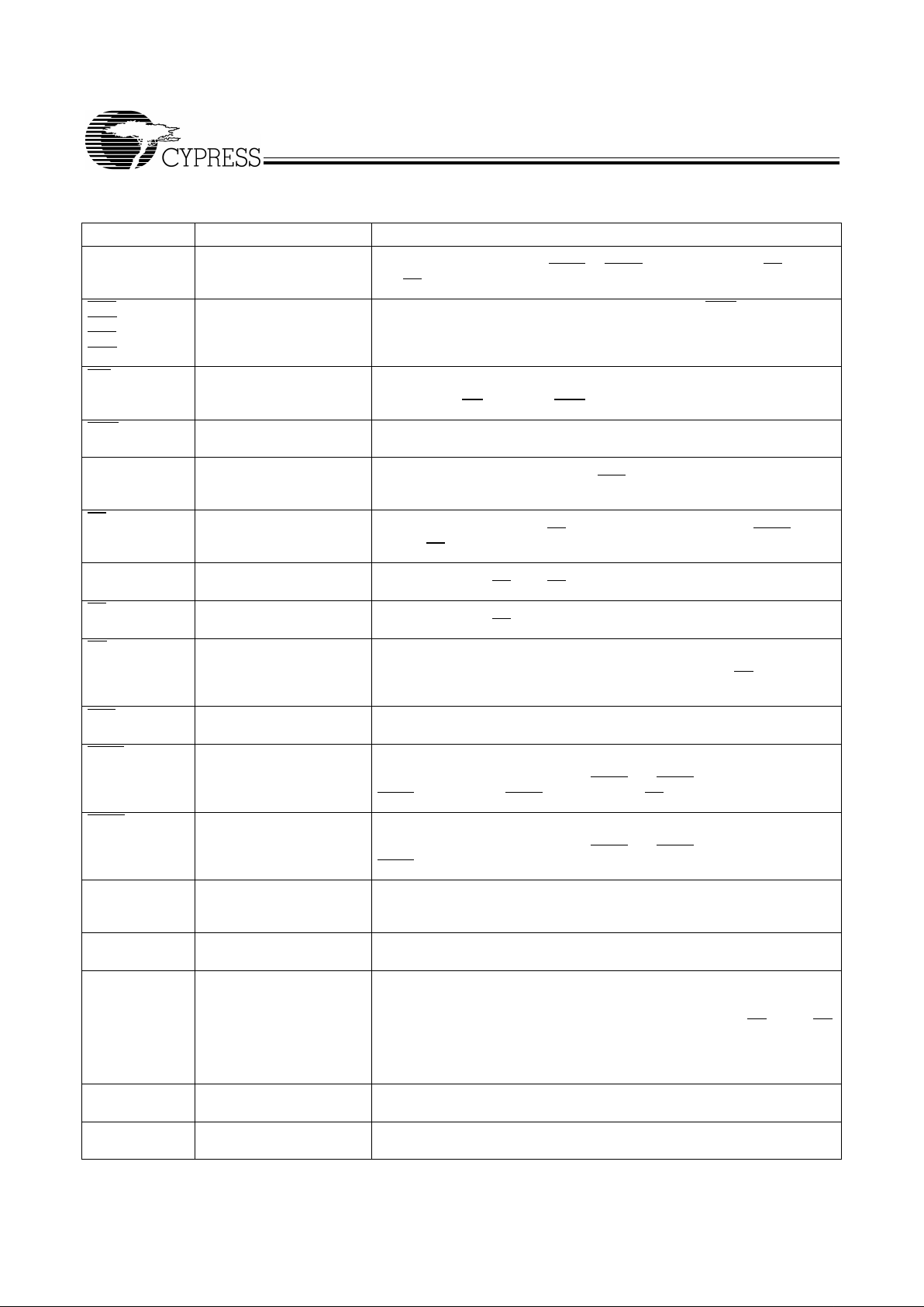
Pin Definitions
Name I/O Description
A0
A1
A
Input-
Synchronous
Address Inputs use d to s elec t one of the addre ss lo cations. Sampled at
the rising edge of the CLK if ADSP
or ADSC is active LOW, and CE1, CE2,
and
CE3
are sampled active. A
[1:0]
feed the 2-bit counter .
BWa
BWb
BWc
BWd
Input-
Synchronous
Byte Write Select Inputs, active LOW. Qualified with BWE to conduct byte
writes to the SRAM. Sampled on the rising edge of CLK.
GW Input-
Synchronous
Global Write Enable Inpu t, ac tive LOW. When asserted LOW on the rising
edge of CLK, a globa l write is cond ucted (ALL byte s are written, regardless of
the values on BW
a,b,c,d and BWE).
BWE Input-
Synchronous
Byte Write Enable Input, active LOW. Sampled on the rising edge of CLK.
This signal must be asserted LOW to conduct a byte write.
CLK Input-Clock Clock Input. Used to capture all sy nchronou s input s to the devi ce. Also used
to increment the burst counter when ADV
is asserted LOW, during a burst
operation.
CE
1
Input-
Synchronous
Chip Enable 1 Input, active LOW. Sampled on the rising edge of CLK. Used
in conjunction with CE
2
and CE3 to select/deselect the device. ADSP is ig-
nored if CE
1
is HIGH.
CE
2
Input-
Synchronous
Chip Enable 2 Input, active HIGH. Sampled on the rising edge of CL K. Used
in conjunction with CE
1
and CE3 to select/deselect the device. (TQFP Only)
CE
3
Input-
Synchronous
Chip Enable 3 Input, active LOW. Sampled on the rising edge of CLK. Used
in conjunction with CE
1
and CE2 to select/deselect the device. (TQFP Only)
OE Input-
Asynchronous
Output Enable, asynchronous inp ut, active LOW . Contr ols the directi on of
the I/O pins. When LOW, the I/O pins behave as outputs. When deasserted
HIGH, I/O pins are three-stated, and act as input data pins. OE
is masked
during the first clock of a read cycle when emerging from a deselected state.
ADV Input-
Synchronous
Advance Input signal, sa mpled on the rising edge of CLK. When asserted,
it automatically increments the address in a burst cycle.
ADSP Input-
Synchronous
Address Strobe from Processor, sampled on the rising edge of CLK.
When asserted LOW, A is captured in the address registers. A
[1:0]
are also
loaded into the burs t counter . Wh en ADSP
and ADSC are both asserted, only
ADSP
is recognized. ASDP is ignored when CE1 is deasserted HIGH.
ADSC Input-
Synchronous
Address Strobe from Controller, sampled on the rising edge of CLK.
When asserted LOW , A
[x:0]
is captured in the a ddress registe rs. A
[1:0]
are also
loaded into the burs t counter . Wh en ADSP
and ADSC are both asserted, only
ADSP is recognized.
MODE Input-Pin Selects Burst Order . Wh en tied to GND selects lin ear burst se quence. When
tied to V
DDQ
or left floating select s interleaved burs t sequence. Thi s is a strap
pin and should remain static during device operation.
ZZ Input-
Asynchronous
ZZ “sleep” Input. This active HIGH input places the device in a non-time
critical “sleep” condition with data integrity preserved.
DQa, DPa
DQb, DPb
DQc, DPc
DQd, DPd
I/O-
Synchronous
Bidirectional Data I/O lines. As inputs, they feed into an on-chip data regi ster
that is triggered by the rising edge of CLK. As outputs, they deliver the data
contained in the memory location specified by A
[X]
during the previous clock
rise of the read cycle. The d irecti on of the p ins i s co ntrolle d by OE. W hen OE
is asserted LOW , the pins behav e as outputs. Whe n HIGH, DQx and DPx
are
placed in a three-state condition. DQ a,b,c, and d are 8 bits wide and the DP
a,b,c, and d are 1 bit wide.
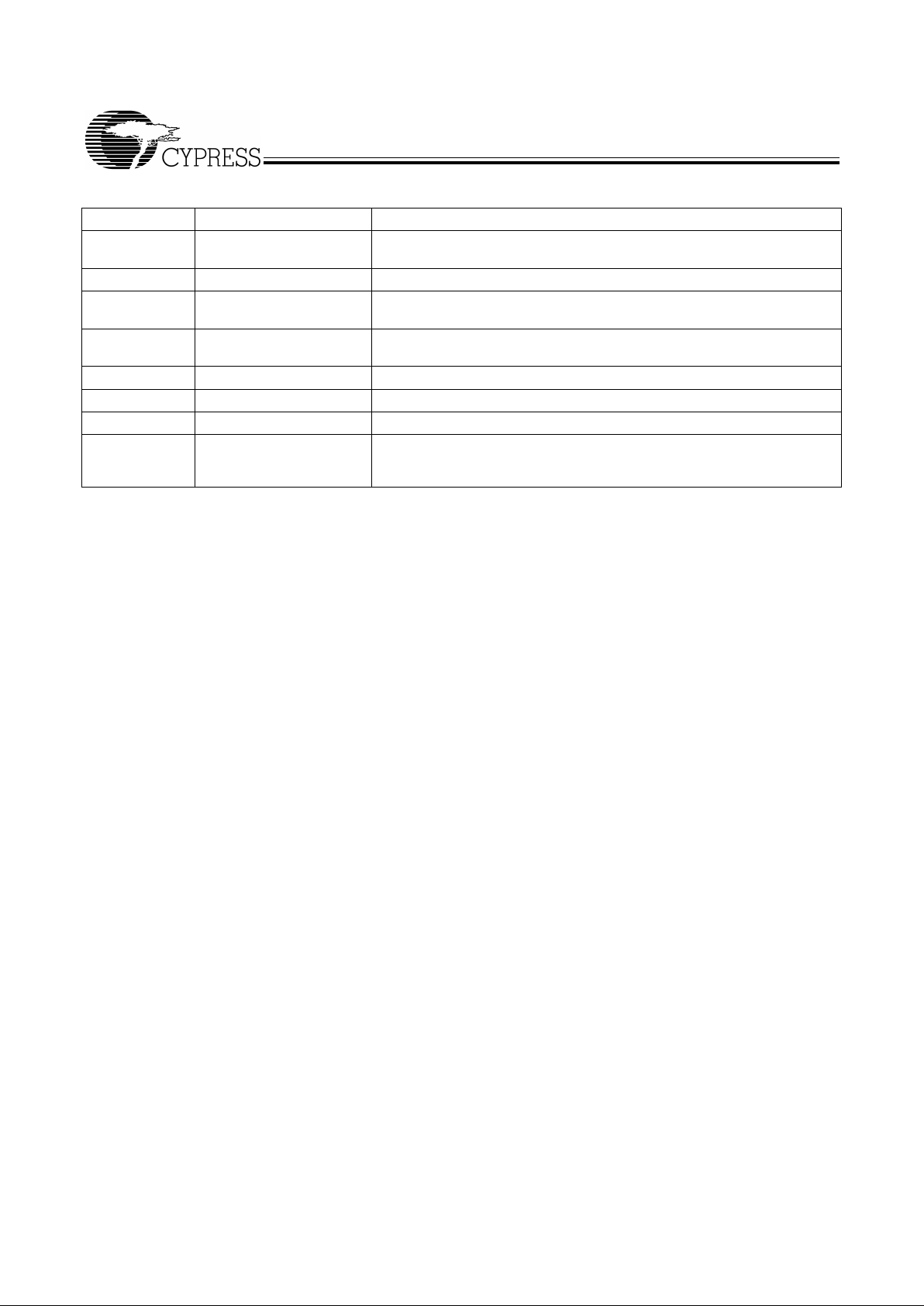
TDO JTAG serial output
Synchronous
Serial data-out to the JTAG circuit. Delivers data on the negative edge of
TCK. (BGA Only)
TDI JTAG serial input
Synchronous
Serial data-in to the JT AG circuit . Sampled on the rising e dge of TCK.(BGA
Only)
CY7C1380CV25
CY7C1382CV25
PRELIMINARY
Document #: 38-05240 Rev. *A Page 7 of 33
TMS Test Mode Select
Synchronous
This pin controls the Test Access Port state machine. Sampled on the
rising edge of TCK. (BGA Only)
TCK JTAG serial clock Serial clock to the JTAG circuit. (BGA Only)
V
DD
Power Supply Power supply inputs to the core of the dev ice. Should be connected to 2.5V
± 5% power su pply.
V
SS
Ground Ground for the core of the device. Should be conne cte d to ground of the
system.
V
DDQ
I/O Power Supply Power supply for the I/O circuitry.
V
SSQ
I/O Ground Ground for the I/O circuitry. Should be connected to ground of the system.
NC - No Connects.Pins are not internally connected.
36M
72M
144M
- No Connects. Reserved for address expansion.
Pin Definitions
Name I/O Description

CY7C1380CV25
CY7C1382CV25
PRELIMINARY
Document #: 38-05240 Rev. *A Page 8 of 33
Introduction
Functional Overview
All synchronous inpu ts pas s through i nput reg isters contro lled
by the rising edge of the clock. All data outputs pass through
output registers control led by the rising edge o f the clock. Maximum access delay from the clock rise (t
CO
) is 2.6 ns (250-MHz
device).
The CY7C1380CV25/CY7C1382CV25 supports secondary
cache in systems utilizing either a linear or interleaved burst
sequence. The interlea ved burst order s upports Pentiu m
®
and
i486 processors. The linear burst sequence is suited for processors that utiliz e a lin ear burst se quenc e. The b urst ord er is
user selecta ble , an d i s d etermined by sampli ng the MO DE i nput. Accesses can be initiated with either the Processor
Address Strobe (ADSP
) or the Controller Address Strobe
(ADSC
). Address advancement th rough the burs t sequence i s
controlled by the ADV
input. A two-bit on-chip wraparound
burst counter captures the first address in a burst sequence
and automatically increments the address for the rest of the
burst access.
Byte write operations are qualified with the Byte Write Enable
(BWE
) and Byte Write Select (BW
a,b,c,d
for CY7C1380V25 and
BW
a,b
for CY7C1382V25) inputs. A Gl obal Write Enab le (GW)
overrides all byte write input s and w rites data to all four by tes.
All writes are simplified with on-chip synchronous self-timed
write circuitry.
Synchronous Chip Select s (CE
1
, CE2, CE3 for TQFP / CE1 for
BGA) and an asynchronous Output Enable (OE
) provide for
easy bank selection and output three-state control. ADSP
is
ignored if CE
1
is HIGH.
Single Read Accesses
This access is initiated when the following conditions are satisfied at clock rise: (1) ADSP
or ADSC is asserted LOW, (2)
chip selects are all asserted active, and (3) the write signals
(GW
, BWE) are all deasserted HIGH. ADSP is ignored if CE
1
is HIGH. The address presented to the address inputs is
stored into the address advancement logic and the Address
Register while being presented to the memory core. The corresponding data is allowed to propagate to the input of the
Output Registers. At the risin g edge of the ne xt cloc k the dat a
is allowed to propagate through the output register and onto
the data bus within 2.6 ns (250-MHz device) if OE
is active
LOW. The only exception occurs when the SRAM is emerging
from a deselected state to a selected state, its outputs are
always three-stated during the first cycle of the access. After
the first cycle of the access, the outputs are controlled by the
OE
signal. Consecutive single read cycles are supported.
Once the SRAM is deselected at clock rise by the chip select
and either ADSP
or ADSC signals, its output will thr ee-state
immediately.
Single Write Accesses Initiated by ADSP
This access is initiated when both of the following conditions
are satisfied at clock rise: (1) ADSP
is asserted LOW, and (2)
chip select is asserted active. The address presented is loaded into the address register and the address advancement
logic while being deli vered to the RAM c ore. The wr ite signal s
(GW
, BWE, and BWx) and ADV inputs are ignored during this
first cycle.
ADSP
triggered write accesses require two clock cycles to
complete. If GW
is asserted LOW on the second clock rise, th e
data presented to the DQx inputs is written into the corresponding address location in the RAM core. If GW
is HIGH,
then the write operation is controlled by BWE
and BWx signals. The CY7C1380CV25/CY7C1382CV25 provides byte
write capabi li ty t h at i s de sc r ibe d i n th e wr ite c ycl e de s cri pt i on
table. Asserting the Byte Write Enable input (BWE
) with the
selected Byte Write (BWa,b,c,d for CY7C1380CV25 and
BW
a,b for CY7C1382CV25) input will selectively write to only
the desired bytes. Bytes not selec ted during a byte write op eration will remain unaltered. A synchronous self-timed write
mechanism has b een provided to simpli fy the write operatio ns.
Because the CY7C1380CV25/CY7C1382CV25 is a common
I/O device, the output enable (OE
) must be deasserted HIGH
before presenting data to the DQ
inputs. Doing so will threestate the output drivers. As a safety precaution, DQ are automatically three-stated whenever a write cycle is detected, regardless of the state of OE
.
Single Write Accesses Initiated by ADSC
ADSC write accesses are initiated when the following conditions are satisfied: (1) ADSC
is asserted LOW, (2) ADSP is
deasserted HIGH, (3) chip select is asserted active, and (4)
the appropriate combination of the write inputs (GW
, BWE,
and BW
x) are asserted active to con duct a write to the des ired
byte(s). ADSC
triggered write accesses require a single clock
cycle to complete. The address presented to A
[17:0]
is loaded
into the address register and the address advancement logic
while being delivered to the RAM core. The ADV
input is ig nored during this cycle. If a g lobal write is co nduct ed, the dat a
presented to the DQ[x:0] is written into the corresponding address location in the RAM core. If a byte write is conducted,
only the selected bytes are written. Bytes not selected during
a byte write operation will remain unaltered. A synchronous
self-timed write mechanism has been provided to simplify the
write operations.
Because the CY7C1380CV25/CY7C1382CV25 is a common
I/O device, the output enable (OE
) must be deasserted HIGH
before presenting data to the DQ[x:0] inputs. Doing so will
three-state the output drivers. As a saf ety pr ecauti on, DQ[x:0]
are automatically three-stated whenever a write cycle is detected, regardless of the state of OE
.
Burst Sequences
The CY7C1380CV25/CY7C1382CV25 provides a two-bit
wraparound counter, fed by A
[1:0]
, that implements either an
interleaved or linear burst s equence. The interle aved burst sequence is designed specifically to support Intel
®
Pentium applications. The linear burst sequence is designed to support
processors that follow a linear burst sequence. The burst sequence is user selectable through the MODE input.
Asserting ADV
LOW at clock rise will automa tic al ly increment
the burst counter to the next address in the burst sequence.
Both read and write burst operations are supported.

CY7C1380CV25
CY7C1382CV25
PRELIMINARY
Document #: 38-05240 Rev. *A Page 9 of 33
Sleep Mode
The ZZ input pin is an asynchronous input. Asserting ZZ places the SRAM in a power conservation “sleep” mode. T wo clock
cycles are required to enter into or exit from this “sleep” mode.
While in this mode, data integrity is guaranteed. Accesses
pending when entering the “sleep” mode are not considered
valid nor is the completion of the operation guaranteed. The
device must be d ese lected prior to ent ering the “sleep” mode.
CE
s, ADSP, and ADSC must remain inactive for the duration
of t
ZZREC
after the ZZ input returns LOW.
Interleaved Burst Sequence
First
Address
Second
Address
Third
Address
Fourth
Address
A
[1:0]]
A
[1:0]
A
[1:0]
A
[1:0]
00 01 10 11
01 00 11 10
10 11 00 01
11 10 01 00
Linear Burst Sequence
First
Address
Second
Address
Third
Address
Fourth
Address
A
[1:0]
A
[1:0]
A
[1:0]
A
[1:0]
00 01 10 11
01 10 11 00
10 11 00 01
11 00 01 10
ZZ Mode Electrical Characteristics
Parameter Description Test Conditions Min. Max. Unit
I
DDZZ
Sleep mode stand-
by current
ZZ > VDD − 0.2V 60 mA
t
ZZS
Device operation to ZZZZ > VDD − 0.2V 2t
CYC
ns
t
ZZREC
ZZ recovery time ZZ < 0.2V 2t
CYC
ns
CY7C1380CV25
CY7C1382CV25
PRELIMINARY
Document #: 38-05240 Rev. *A Page 10 of 33
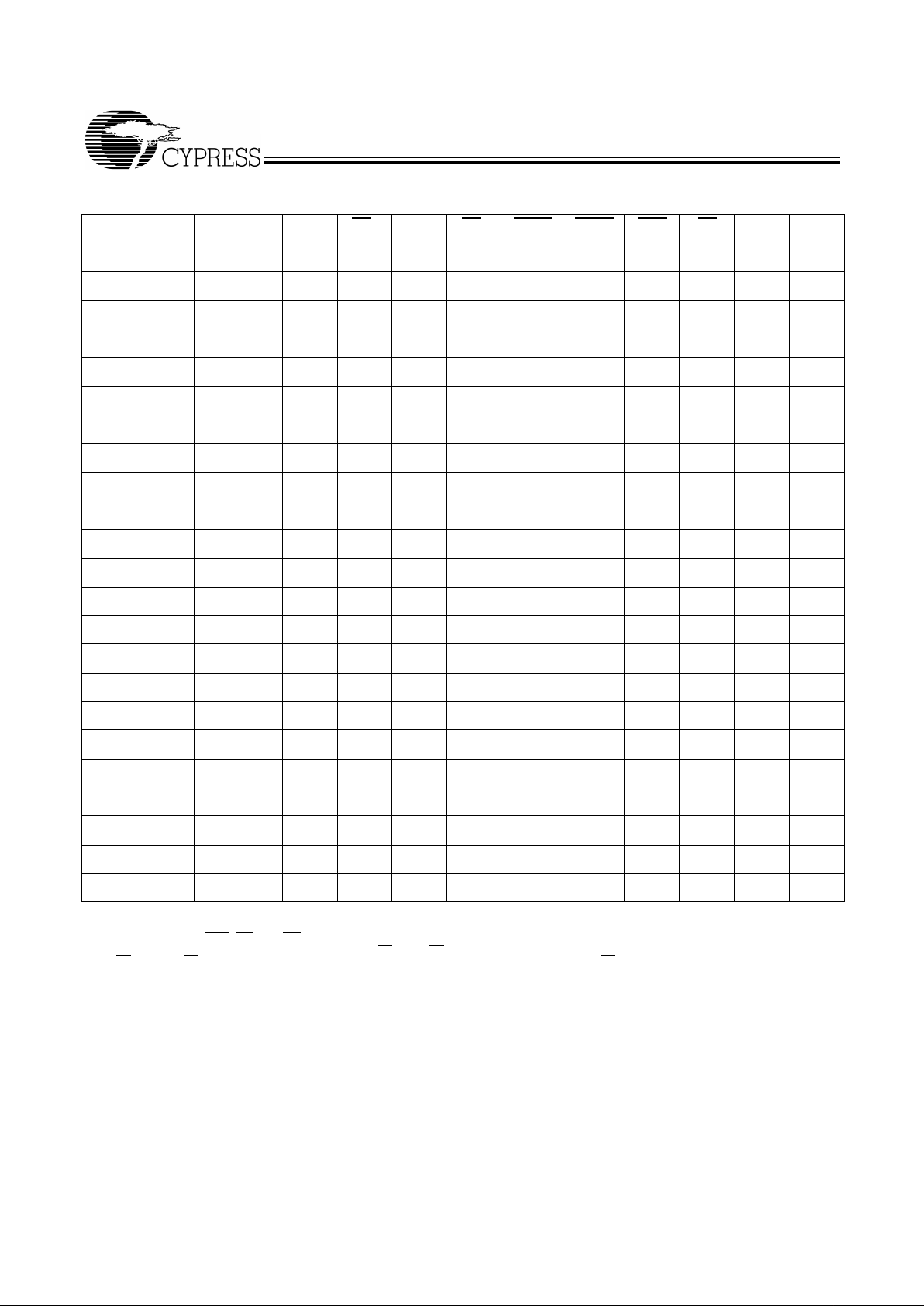
Cycle Descriptions
[1, 2, 3, 4]
Next Cycle Add. Used ZZ CE
3
CE
2
CE
1
ADSP ADSC ADV OE DQ Write
Unselected None 0 X X 1 X 0 X X Hi-Z X
Unselected None 0 1 X 0 0 X X X Hi-Z X
Unselected None 0 X 0 0 0 X X X Hi-Z X
Unselected None 0 1 X 0 1 0 X X Hi-Z X
Unselected None 0 X 0 0 1 0 X X Hi-Z X
Begin Read External 0 0 1 0 0 X X X Hi-Z X
Begin Read External 0 0 1 0 1 0 X X Hi-Z Read
Continue Read Next 0 X X X 1 1 0 1 Hi-Z Re ad
Continue Read Next 0 X X X 1 1 0 0 DQ Read
Continue Read Next 0 X X 1 X 1 0 1 Hi-Z Read
Continue Read Next 0 X X 1 X 1 0 0 DQ Read
Suspend Read Current 0 X X X 1 1 1 1 Hi-Z Read
Suspend Read Current 0 X X X 1 1 1 0 DQ Read
Suspend Read Current 0 X X 1 X 1 1 1 Hi-Z Read
Suspend Read Current 0 X X 1 X 1 1 0 DQ Read
Begin Write Current 0 X X X 1 1 1 X Hi-Z Write
Begin Write Current 0 X X 1 X 1 1 X Hi-Z Write
Begin Write External 0 0 1 0 1 0 X X Hi-Z Write
Continue Write Next 0 X X X 1 1 0 X Hi-Z Write
Continue Write Next 0 X X 1 X 1 0 X Hi-Z Write
Suspend Write Current 0 X X X 1 1 1 X Hi-Z Write
Suspend Write Current 0 X X 1 X 1 1 X Hi-Z Write
ZZ “sleep” None 1 X X X X X X X Hi-Z X
Notes:
1. X = “Don't Care,” 1 = HIGH, 0 = LOW.
2. Write is defined by BWE
, BWx, and GW. See Write Cycle Descriptions table.
3. The DQ pins are controlled by the current cycle and the OE
signal. OE is asynchronous and is not sampled with the clock.
4. CE1, CE2 and CE3 are available only in the TQFP package. The BGA package has a single chip select, CE1.

CY7C1380CV25
CY7C1382CV25
PRELIMINARY
Document #: 38-05240 Rev. *A Page 11 of 33
Notes:
5. The SRAM always initiates a read cycle when ADSP
asserted, regardless of the state of GW, BWE, or BWx. Writes may occur only on subsequent clocks after
the ADSP or with the assertion of ADSC. As a result, OE must be driven HIGH prior to the start of the write cycle to allow the outputs to three-state. OE is a
“don't care” for the remainder of the write cycle.
6. OE
is asynchronous and is not sampled with the clock rise. It is masked internally during write cycles. During a read cycle DQ = High-Z when OE is inactive or
when the device is deselected, and DQ = data when OE is active.
Write Cycle Descriptions
[1, 5, 6]
Function (1380CV25) GW BWE BWdBWcBWbBWa
Read 11XXXX
Read 101111
Write Byte 0 – DQa 101110
Write Byte 1 – DQb 101101
Write Bytes 1, 0 101100
Write Byte 2 – DQc 101011
Write Bytes 2, 0 101010
Write Bytes 2, 1 101001
Write Bytes 2, 1, 0 1 0 1 0 0 0
Write Byte 3 – DQd 100111
Write Bytes 3, 0 100110
Write Bytes 3, 1 100101
Write Bytes 3, 1, 0 1 0 0 1 0 0
Write Bytes 3, 2 100011
Write Bytes 3, 2, 0 1 0 0 0 1 0
Write Bytes 3, 2, 1 1 0 0 0 0 1
Write All Bytes 1 0 0 0 0 0
Write All Bytes 0 X X X X X
Function (1382CV25) GW BWE BWbBWa
Read 1 1 X X
Read 1 0 1 1
Write Byte 0 – DQ
[7:0]
and DP
0
1010
Write Byte 1 – DQ
[15:8]
and DP
1
1001
Write All Bytes 1 0 0 0
Write All Bytes 0 X X X

CY7C1380CV25
CY7C1382CV25
PRELIMINARY
Document #: 38-05240 Rev. *A Page 12 of 33
IEEE 1149 .1 Serial Boundary Scan (JTAG)
The CY7C1380CV25/CY7C1382CV25 incorporates a serial
boundary scan Test Access Port (TAP) in the BGA package
only . The TQFP packa ge does not of fer this function ality. This
port operates in accorda nce with IEEE S ta ndard 1 14 9.1-1900,
but does not have the set of functions required for full 1149.1
compliance. These functions from the IEEE specification are
excluded because the ir inclusion pl aces an added dela y in the
critical s pee d pat h o f t h e SR AM . Note that th e TAP contro l le r
functions in a man ner that does not conflic t wit h the operation
of other devi ces usi ng 1149.1 fully com plian t TAPs. The TAP
operates using JEDEC standard 2.5V I/O logic levels.
Disabling the JTAG Feature
It is possible to operate the SRAM without using the JTAG
feature. To disable the T AP c ontroller, TCK must be tied LOW
(V
SS
) to prevent clocking of the device. TDI and TMS are internally pulled up and may be unconnected. They may alternately be connected to V
DD
through a pull-up resistor. TDO
should be left unconnected. Upon power-up, the device will
come up in a reset state whic h wil l not interfere with the operation of the device.
Test Access Port (TAP)—Test Clock
The test clock is used only with the TAP controller. All inputs
are captured on the ri si ng edge of TCK. All outputs are driven
from the falling edge of TCK.
Test Mode Select
The TMS input is used to giv e commands to the T AP c ontroller
and is sampled on the rising edge of TCK. It is allowable to
leave this pin unconnected if the TAP is not used. The pin is
pulled up internally, resulting in a logic HIGH level.
Test Data-In (TDI)
The TDI pin is used to s eri al ly inp ut i nfo rmation into the registers and can be co nne cte d to the in put of any of the registers .
The register between TDI and TDO is chosen by the instruction that is loaded into the TAP instruction register. For information on loading the instruction register, see the TAP Controller State Diagram. TDI is internally pulled up and can be
unconnected if the TAP is unused in an application. TDI is
connected to the Most Significant Bit (MSB) on any register.
Test Data Out (TDO)
The TDO output pin is us ed to s eri all y c lock data-out from the
registers. The e output is active depending upon the current
state of the TAP state machine (see TAP Controller State
Diagram). The output changes on the falling edge of TCK.
TDO is connected to the Least Significant Bit (LSB) of any
register.
Performing a TAP Reset
A Reset is performed by forc ing TMS HIGH (V
DD
) for five rising
edges of TCK. This RESET does not affect the operation of
the SRAM and may be performed while the SRAM is operating. At power-up, the TAP is reset internally to ensure that TDO
comes up in a high-Z state.
TAP Registers
Registers are connected between the TDI and TDO pins and
allow data to be sca nned into and out of the SRAM test circu it-
ry. Only one register can be selected at a time through the
instruction registers . Dat a is seriall y loaded into the TDI pin on
the rising edge of TCK. Data is output on the TDO pin on the
falling edge of TCK.
Instruction Register
Three-bit instructi ons can be serially loa ded into the instruc tion
register. This register is loaded when it is placed between the
TDI and TDO pins as shown in the TAP Controller Block
Diagram. Upon power-up, the instruction register is loaded
with the IDCODE i nstruction. It is al so loaded with the I DCODE
instruction if the controller is placed in a reset state as described in the previous section.
When the T AP controller is in the CaptureIR state, the two least
significant bits ar e loaded with a bina ry “01” pattern to allow f or
fault isolation of the board level serial test path.
Bypass Register
To save time when serially shifting data through registers, it is
sometimes advantageous to skip certain states. The bypass
register is a singl e-bit regis ter that c an be pl aced betwe en TDI
and TDO pins. This allows data to be shifted through the
SRAM with minimal delay. The bypass register is set LOW
(VSS) when the BYPASS instruction is executed.
Boundary Scan Register
The boundary scan register is connected to all the input and
output pins on the SRAM. Several no connect (NC) pins are
also included in the scan register to reserve pins for higher
density devices. The x36 configuration has a 70-bit-long register, and the x18 configuration has a 51-bit-long register.
The boundary scan register is loaded with the contents of the
RAM Input and Output ring when the TAP controller is in the
Capture-DR state and is then placed between the TDI and
TDO pins when the controller is moved to the Shift-DR state.
The EXTEST, SAMPLE/PRELOAD and SAMPLE Z instructions can be used to capture the contents of the Input and
Output ring.
The Boundary Scan Order tables show the order in which the
bits are con nec ted . Ea ch bit corresponds to on e o f t he bum ps
on the SRAM package. The MSB of the r egister is connected
to TDI, and the LSB is connected to TDO.
Identification (ID) Register
The ID register is loaded with a vendor-specific, 32-bit code
during the Capture-DR state when the IDCODE command is
loaded in the instruction register. The IDCODE is hardwired
into the SRAM and can be shifted out wh en the TAP controller
is in the Shift-DR s tate. The ID re gister ha s a ven dor code and
other information d esc rib ed in the Identificatio n Reg ist er D ef initions table.
TAP Instruction Set
Eight different instructions are possible with the three-bit instruction register. All combinations are listed in the Ins truc tio n
Code table. Three of these instructions are listed as RESERVED and should not be used. The other five instructions
are described in detail below.
The TAP controller used in th is SRAM i s n ot fu lly com pli ant to
the 1 149.1 con vention because some of the mandatory 1 1 49.1
instructions are not ful ly implemented. Th e T AP controlle r cannot be used to load address, data or control signals into the

CY7C1380CV25
CY7C1382CV25
PRELIMINARY
Document #: 38-05240 Rev. *A Page 13 of 33
SRAM and cannot preload the Input or Output buffers. The
SRAM does not implement the 1149.1 commands EXTEST or
INTEST or the PRELOAD portion of SAMPLE/PRELOAD;
rather it performs a capture of the Input s and Output ring when
these instructions are exe cu ted .
Instructions are loaded into the T AP controller during the ShiftIR state when the instruction register is placed between TDI
and TDO. During this st ate, instructions are shifted through the
instruction register thro ugh the TDI and TDO pi ns. To execute
the instruction once it is shifte d in, th e TAP controller needs to
be moved into the Update-IR state.
EXTEST
EXTEST is a mandatory 1149.1 instruction which is to be executed whenever the instruction register is loaded with all 0s.
EXTEST is not implemented in the TAP controller, and therefore this device is not compliant to the 1149.1 standard.
The TAP controller does recognize an all-0 instruction. When
an EXTEST instruction is loaded into the instruction register,
the SRAM responds as if a SAMPLE/PRELOAD instruction
has been loaded. There is one difference between the two
instructions. Unlike the SAMPLE/PRELOAD instruction, EXTEST places the SRAM outputs in a High-Z state.
IDCODE
The IDCODE instruc tion causes a ve ndor-specific, 32-bit code
to be loaded into the instruction register. It also places the
instruction register be tween the TDI and TDO pi ns and a llows
the IDCODE to be shifted out of the device when the TAP
controller enters the Shift-DR state. The IDCODE instruction
is loaded into the instruction register upo n po wer-up or whenever the TAP controller is given a test logic reset state.
SAMPLE Z
The SAMPLE Z instruction c auses the b oundary scan register
to be connected b etween the TD I and TDO p ins when the T AP
controller is in a Shift-D R state. It also plac es all SRAM outputs
into a High-Z state.
SAMPLE/PRELOAD
SAMPLE/PRELOAD is a 1149.1 mandatory instruction. The
PRELOAD portion of this instruction is not implemented, so
the TAP controller is not fully 1149.1 compliant.
When the SAMPLE/PRELOAD instruction is loaded into the
instruction register and the T AP co ntroller is in t he Capture-DR
state, a snapshot of dat a o n the inputs and output pins is ca ptured in the boundary scan register.
The user must be aw are that the TAP controller clock can only
operate at a frequency up to 10 MHz, while the SRAM clock
operates more than an order of magnitude faster. Because
there is a large difference in the clock frequencies, it is possible that during the Capture-DR state, an input or output will
undergo a transiti on. The TAP may then try to capture a si gnal
while in tr ansition (metastab le state). This will not harm the
device, but there is no guarantee as to the value that will be
captured. Repeatable results may not be possible.
To guarantee that the boundary scan register will capture the
correct value of a signal, the SRAM signal must be stabilized
long enough to meet the TAP controller’s capture set-up plus
hold times (t
CS
and tCH). The SRAM clock input might not be
captured correctly if there is no way in a design to stop (or
slow) the clock during a SAMPLE/PREL OAD instruction. If this
is an issue, it is still possible to capture all other signals and
simply ignore the value of the CK and CK
captured in the
boundary scan register.
Once the data is captured, i t is poss ible to s hift out the data b y
putting the T AP in to the Shift-DR st ate. This pl aces the boun dary scan register between the TDI and TDO pins.
Note that since the PRELOAD part of the command is not
implemented, putting the TAP into the Update to the UpdateDR state while performing a SAMPLE/PRELOAD instruction
will have the same effect as the Pause-DR command.
Bypass
When the BYP ASS instruc tion is lo aded in the in struction register and the TAP is placed in a Shift-DR state, the bypass
register is placed betwe en the TDI and TDO pi ns. The ad vantage of the BYP ASS i nstruction is that it shortens the b oundary
scan path when m ult ipl e d ev ices are connected to gether on a
board.
Reserved
These instructions are not implemented but are reserved for
future use. Do not use these instructions.

CY7C1380CV25
CY7C1382CV25
PRELIMINARY
Document #: 38-05240 Rev. *A Page 14 of 33
TAP Controller State Diagram
TEST-LOGIC
RESET
TEST-LOGIC/
IDLE
SELECT
DR-SCAN
CAPTURE-DR
SHIFT-DR
EXIT1-DR
PAUSE-DR
EXIT2-DR
UPDATE-DR
SELECT
IR-SCAN
CAPTURE-DR
SHIFT-IR
EXIT1-IR
PAUSE-IR
EXIT2-IR
UPDATE-IR
1
0
1
1
0
1
0
1
0
0
0
1
1
1
0
1
0
1
0
0
0
1
0
1
1
0
1
0
0
1
1
Note: The 0/1 next to each state represents the value at TMS at the rising edge of TCK.

CY7C1380CV25
CY7C1382CV25
PRELIMINARY
Document #: 38-05240 Rev. *A Page 15 of 33
TAP Controller Block Diagram
0
012..
29
3031
Boundary Scan Register
Identification Register
012..
.
.x
012
Instruction Register
Bypass Registe r
Selection
Circuitry
Selection
Circuitry
TAP Controller
TDI
TDO
TCK
TMS
TAP Electrical Characteristics Over the Operating Range
[7, 8]
Parameter Description Test Conditions Min. Max. Unit
V
OH1
Output HIGH Voltage I
OH
= −1.0 mA 1.7 V
V
OH2
Output HIGH Voltage I
OH
= −100 µA 2.1 V
V
OL1
Output LOW Voltage IOL = 1.0 mA 0.4 V
V
OL2
Output LOW Voltage IOL = 100 µA 0.2 V
V
IH
Input HIGH Voltage 1.7 V
DD
+ 0.3 V
V
IL
Input LOW Voltage −0.3 0.7 V
I
X
Input Load Current GND < VI < V
DDQ
−5 5 µA
Notes:
7. All Voltage referenced to Ground.
8. Overshoot: V
IH
(AC) < VDD+1.5V for t < t
TCYC
/2, Undershoot: VIL(AC) > −0.5V for t < t
TCYC
/2.

CY7C1380CV25
CY7C1382CV25
PRELIMINARY
Document #: 38-05240 Rev. *A Page 16 of 33
TAP AC Switching Characteristics Over the Operating Range
[9, 10]
Parameters Description Min. Max Unit
t
TCYC
TCK Clock Cycle Time 100 ns
t
TF
TCK Clock Frequency 10 MHz
t
TH
TCK Clock HIGH 40 ns
t
TL
TCK Clock LOW 40 ns
Set-up Times
t
TMSS
TMS Set-up to TCK Clock Rise 10 ns
t
TDIS
TDI Set-up to TCK Clock Rise 10 ns
t
CS
Capture Set-up to TCK Rise 10 ns
Hold Times
t
TMSH
TMS Hold after TCK Clock Rise 10 ns
t
TDIH
TDI Hold after Clock Rise 10 ns
t
CH
Capture Hold after Clock Rise 10 ns
Output Times
t
TDOV
TCK Clock LOW to TDO Valid 20 ns
t
TDOX
TCK Clock LOW to TDO Invalid 0 ns
Notes:
9. t
CS
and tCH refer to the set-up and hold time requirements of latching data from the boundary scan register.
10. Test conditions are specified using the load in TAP AC Test Conditions. t
R/tF
= 1 V/ns.

CY7C1380CV25
CY7C1382CV25
PRELIMINARY
Document #: 38-05240 Rev. *A Page 17 of 33
TAP Timing and Test Conditions
(a)
TDO
C
L
= 20 pF
Z
0
= 50Ω
GND
1.25V
50Ω
2.5V
0V
ALL INPUT PULSES
1.25V
Test Clock
Test Mode Select
TCK
TMS
Test Data-In
TDI
Test Data-Out
t
TCYC
t
TMSH
t
TL
t
TH
t
TMSS
t
TDIS
t
TDIH
t
TDOV
t
TDOX
TDO

CY7C1380CV25
CY7C1382CV25
PRELIMINARY
Document #: 38-05240 Rev. *A Page 18 of 33
Identification Register Definiti ons
Instruction Field 512K x 36 1M x 18 Description
Revision Number
(31:28)
0100 0100 Reserved for version number
Cypress Device ID
(27:24)
1011 1011 Reserved for internal use
Device Type
(23:18)
000000 000000 Defines memory type and architecture
Device Width and Dens ity
(17:12)
100101 010101 Defines width and density
Cypress JEDEC ID
(11:0)
000001101001 000001101001 Allows unique identification of SRAM
vendor
Scan Register Sizes
Register Name Bit Size (x18) Bit Size (x36)
Instruction 3 3
Bypass 1 1
ID 32 32
Boundary Scan 51 70
Identification Codes
Instruction Code Description
EXTEST 000 Captures the Input/Output rin g contents . Places the bound ary scan register
between the TDI and TDO. Forces all SRAM outputs to High-Z state. This
instruction is not 1149.1 compliant.
IDCODE 001 Loads the ID register with the vendor ID code and places the register be-
tween TDI and TDO. This operation does not affect SRAM operation.
SAMPLE Z 010 Captures the Input/Output contents. Places the boundary scan register be-
tween TDI and TDO. Forces all SRAM output drivers to a High-Z state.
RESERVED 011 Do Not Use: This instruction is reserved for future use.
SAMPLE/PRELOAD 100 Captures the Input/O utput ring content s. Places th e boundary scan reg ister
between TDI and TDO . Does not affect the SRAM operation. This instruction
does not implement 1149.1 preload function and is therefore not 1149.1
compliant.
RESERVED 101 Do Not Use: This instruction is reserved for future use.
RESERVED 110 Do Not Use: This instruction is reserved for future use.
BYPASS 111 Places th e byp ass re gister betwe en TDI a nd TD O. Thi s opera tion d oes no t
affect SRAM operation.

CY7C1380CV25
CY7C1382CV25
PRELIMINARY
Document #: 38-05240 Rev. *A Page 19 of 33
Boundary Scan Order (512K x 36)
Bit #
Signal
Name
Bump
ID Bit #
Signal
Name
Bump
ID
1 TBD TBD 36 TBD TBD
2 TBD TBD 37 TBD TBD
3 TBD TBD 38 TBD TBD
4 TBD TBD 39 TBD TBD
5 TBD TBD 40 TBD TBD
6 TBD TBD 41 TBD TBD
7 TBD TBD 42 TBD TBD
8 TBD TBD 43 TBD TBD
9 TBD TBD 44 TBD TBD
10 TBD TBD 45 TBD TBD
11 TBD TBD 46 TBD TBD
12 TBD TBD 47 TBD TBD
13 TBD TBD 48 TBD TBD
14 TBD TBD 49 TBD TBD
15 TBD TBD 50 TBD TBD
16 TBD TBD 51 TBD TBD
17 TBD TBD 52 TBD TBD
18 TBD TBD 53 TBD TBD
19 TBD TBD 54 TBD TBD
20 TBD TBD 55 TBD TBD
21 TBD TBD 56 TBD TBD
22 TBD TBD 57 TBD TBD
23 TBD TBD 58 TBD TBD
24 TBD TBD 59 TBD TBD
25 TBD TBD 60 TBD TBD
26 TBD TBD 61 TBD TBD
27 TBD TBD 62 TBD TBD
28 TBD TBD 63 TBD TBD
29 TBD TBD 64 TBD TBD
30 TBD TBD 65 TBD TBD
31 TBD TBD 66 TBD TBD
32 TBD TBD 67 TBD TBD
33 TBD TBD 68 TBD TBD
34 TBD TBD 69 TBD TBD
35 TBD TBD 70 TBD TBD
Boundary Scan Order (1M x 18)
Bit #
Signal
Name
Bump
ID Bit #
Signal
Name
Bump
ID
1 TBD TBD 36 TBD TBD
2 TBD TBD 37 TBD TBD
3 TBD TBD 38 TBD TBD
4 TBD TBD 39 TBD TBD
5 TBD TBD 40 TBD TBD
6 TBD TBD 41 TBD TBD
7 TBD TBD 42 TBD TBD
8 TBD TBD 43 TBD TBD
9 TBD TBD 44 TBD TBD
10 TBD TBD 45 TBD TBD
11 TBD TBD 46 TBD TBD
12 TBD TBD 47 TBD TBD
13 TBD TBD 48 TBD TBD
14 TBD TBD 49 TBD TBD
15 TBD TBD 50 TBD TBD
16 TBD TBD 51 TBD TBD
17 TBD TBD 52 TBD TBD
18 TBD TBD 53 TBD TBD
19 TBD TBD 54 TBD TBD
20 TBD TBD 55 TBD TBD
21 TBD TBD 56 TBD TBD
22 TBD TBD 57 TBD TBD
23 TBD TBD 58 TBD TBD
24 TBD TBD 59 TBD TBD
25 TBD TBD 60 TBD TBD
26 TBD TBD 61 TBD TBD
27 TBD TBD 62 TBD TBD
28 TBD TBD 63 TBD TBD
29 TBD TBD 64 TBD TBD
30 TBD TBD 65 TBD TBD
31 TBD TBD 66 TBD TBD
32 TBD TBD 67 TBD TBD
33 TBD TBD 68 TBD TBD
34 TBD TBD 69 TBD TBD
35 TBD TBD 70 TBD TBD

CY7C1380CV25
CY7C1382CV25
PRELIMINARY
Document #: 38-05240 Rev. *A Page 20 of 33
Maximum Ratings
(Above which the useful life may be impaired. For user guidelines, not tested.)
Storage Temperature .................................–55°C to +150°C
Ambient Temperature with
Power Applied.............................................–55°C to +125°C
Supply Voltage on V
DD
Relative to GND ....... –0.3V to +3.6V
DC Voltage Applied to Outputs
in High Z State
[11]
................................ –0.5V to V
DDQ
+ 0.5V
DC Input Voltage
[11]
............................ –0.5V to V
DDQ
+ 0.5V
Current into Outputs (LOW).........................................20 mA
Static Discharge Voltage........................................... >2001V
(per MIL-STD-883, Method 3015)
Latch-Up Current.................................................... >200 mA
Notes:
11. Minimum voltage equals –2.0V for pulse durations of less than 20 ns.
12. T
A
is the temperature.
Operating Range
Range
Ambient
Temp.
[12]
V
DD/VDDQ
Com’l 0°C to 70°C 2.5V ± 5%
Ind’l –40°C to +85°C
Electrical Characteristics Ov er the Op erat ing Range
Parameter Description Test Conditions Min. Max. Unit
VDD/V
DDQ
Power Supply Voltage 2.375 2.625 V
V
OH
Output HIGH Voltage VDD = Min., I
OH
= −1.0 mA 2.0 V
V
OL
Output LOW Voltage VDD = Min., IOL = 1.0 mA 0.4
V
IH
Input HIGH Voltage 1.7 VDD +
0.3
V
IL
Input LOW Voltage
[11]
–0.3 0.7
I
X
Input Load Current
except ZZ and MODE
GND < VI < V
DDQ
–5 5 µA
I
ZZ
Input Current of MODE −30 30 µA
Input Current of ZZ Input = V
SS
−30 30 µA
I
OZ
Output Leakage Current GND < VI < V
DDQ,
Output Disabled –5 5 µA
I
DD
VDD Operating Supply V
DD
= Max., I
OUT
= 0 mA,
f = f
MAX
= 1/t
CYC
4.0-ns cycle, 250 MHz 350 mA
4.4-ns cycle, 225 MHz 325 mA
5.0-ns cycle, 200 MHz 300 mA
6.0-ns cycle, 167 MHz 275 mA
I
SB1
Automatic CE PowerDown Current—TTL Inputs
Max. VDD, Device Deselected,
V
IN
> VIH or VIN < V
IL
f = f
MAX
= 1/t
CYC
4.0-ns cycle, 250 MHz 120 mA
4.4-ns cycle, 225 MHz 110 mA
5.0-ns cycle, 200 MHz 100 mA
6.0-ns cycle, 167 MHz 90 mA
I
SB2
Automatic CE PowerDown Current—CMOS
Inputs
Max. V
DD
, Device Deselected,
V
IN
< 0.3V or VIN > V
DDQ
– 0.3V,
f = 0
All speed grades 70 mA
I
SB3
Automatic CE PowerDown Current—CMOS
Inputs
Max. V
DD
, Device Deselected, or
V
IN
< 0.3V or VIN > V
DDQ
– 0.3V
f = f
MAX
= 1/t
CYC
4.0-ns cycle, 250 MHz 105 mA
4.4-ns cycle, 225 MHz 100 mA
5.0-ns cycle, 200 MHz 95 mA
6.0-ns cycle, 167 MHz 85 mA
I
SB4
Automatic CE PowerDown Current—TTL Inputs
Max. VDD, Device Deselected,
V
IN
> VIH or VIN < VIL, f = 0
All Speeds 80 mA
Shaded areas contain advance information.

CY7C1380CV25
CY7C1382CV25
PRELIMINARY
Document #: 38-05240 Rev. *A Page 21 of 33
Capacitance
[13]
Parameter Description Test Conditions
Max.
Unit100-TQFP 119-BGA 165-FBGA
CIN Input Capacitance TA = 25°C, f = 1 MHz TBD TBD TBD pF
C
CLK
Clock Input C apacitance TBD TBD TBD pF
C
I/O
Input/Output Capacitance TBD TBD TBD pF
AC Test Loads and Waveforms
[14]
OUTPUT
R = 1667Ω
R = 1538Ω
5pF
INCLUDING
JIG AND
SCOPE
(a) (b)
V
DDQ
ALL INPUT PULSES
[10]
2.5V
GND
90%
10%
90%
10%
≤ 1 ns
≤ 1 ns
(c)
OUTPUT
R
t
= 50Ω
Z
0
= 50Ω
V
t
= 1.25
30 pF
V
t
- Termination Voltage
R
t
- Termination Resistance
Thermal Resistance
[13]
Description Test Conditions Symbol TQFP 119 BGA 165 FBGA Unit
Thermal Resistance
(Junction to Ambient)
Still Air , solde red on a 3
x 4.5 inch2, 2-layer
printed circuit board
Θ
JA
31 45 46 °C/W
Thermal Resistance
(Junction to Case)
Θ
JC
673°C/W
Notes:
13. Tested initially and after any design or process changes that may affect these parameters.
14. Input waveform should have a slew rate of <
1 ns.

CY7C1380CV25
CY7C1382CV25
PRELIMINARY
Document #: 38-05240 Rev. *A Page 22 of 33
Switching Characteristics Over the Operating Range
[15, 16, 17]
-250 -225 -200 -167
Parameter Description Min. Max. Min. Max. Min. Max. Min. Max. Unit
t
CYC
Clock Cycle Time 4.0 4.4 5 6 ns
t
CH
Clock HIGH 1.7 2.0 2.0 2.2 ns
t
CL
Clock LOW 1.7 2.0 2.0 2.2 ns
t
AS
Address Set-up Before CLK Rise 1.2 1.4 1.4 1.5 ns
t
AH
Address Hold After CLK Rise 0.3 0.4 0.4 0.5 ns
t
CO
Data Output Valid After CLK Rise 2.6 2.8 3.0 3.4 ns
t
DOH
Data Output Hold After CLK Rise 1.0 1.0 1.3 1.3 ns
t
ADS
ADSP, ADSC Set-up Before CLK Rise 1.2 1.4 1.4 1.5 ns
t
ADH
ADSP, ADSC Hold After CLK Rise 0.3 0.4 0.4 0.5 ns
t
WES
BWE, GW, BWx Set-up Before CLK Rise 1.2 1.4 1.4 1.5 ns
t
WEH
BWE, GW, BWx Hold After CLK Rise 0.3 0.4 0.4 0.5 ns
t
ADVS
ADV Set-up Before CLK Rise 1.2 1.4 1.4 1.5 ns
t
ADVH
ADV Hold After CLK Rise 0.3 0.4 0.4 0.5 ns
t
DS
Data Input Set-up Before CLK Rise 1.2 1.4 1.4 1.5 ns
t
DH
Data Input Hold After CLK Rise 0.3 0.4 0.4 0.5 ns
t
CES
Chip Enable Set-up 1.2 1.4 1.4 1.5 ns
t
CEH
Chip Enable Hold After CLK Rise 0.3 0.4 0.4 0.5 ns
t
CHZ
Clock to High-Z
[16]
2.6 2.8 3.0 3.4 ns
t
CLZ
Clock to Low-Z
[16]
1.0 1.0 1.3 1.3 ns
t
EOHZ
OE HIGH to Output High-Z
[16, 17]
2.6 2.8 3.0 3.4 ns
t
EOLZ
OE LOW to Output Low-Z
[16, 17]
0 0 0 0 ns
t
EOV
OE LOW to Output Valid
[16]
2.6 2.8 3.0 3.4 ns
Shaded areas contain preliminary information.
Notes:
15. Unless otherwise noted, test conditions assume signal transition time of 1 ns or less, timing reference levels of 1.25V, input pulse levels of 0 to 2.5V, and
output loading of the specified I
OL/IOH
and load capacitance. Shown in (a), (b) and (c) of AC Test Loads.
16. t
CHZ
, t
CLZ
, t
OEV
, t
EOLZ
, and t
EOHZ
are specified with a load capacitance of 5 pF as in part (b) of AC Test Loads. Transition is measured ± 200 mV from steady-
state voltage.
17. At any given voltage and temperature, t
EOHZ
is less than t
EOLZ
and t
CHZ
is less than t
CLZ
.

CY7C1380CV25
CY7C1382CV25
PRELIMINARY
Document #: 38-05240 Rev. *A Page 23 of 33
1
Switching Waveforms
Write Cycle Timing
[4, 18, 19, 20]
Notes:
18. WE
is the combination of BWE and BWx to define a write cycle (see Write Cycle Descriptions table).
19. WDx stands for Write Data to Address X.
20. Device originall y dese l ecte d.
ADSP
CLK
ADSC
ADV
ADD
CE
1
OE
GW
WE
CE
2
CE
3
1a
Data
In
t
CYC
t
CH
t
CL
t
ADS
t
ADH
t
ADS
t
ADH
t
ADVS
t
ADVH
WD1
WD2
WD3
t
AH
t
AS
t
WS
t
WH
t
WH
t
WS
t
CES
t
CEH
t
CES
t
CEH
t
CES
t
CEH
2b
3a
1a
Single Write
Burst Write
Unselected
ADSP
ignored with CE1 inactive
CE
1
masks ADSP
= DON’T CARE
= UNDEFINED
Pipelined Write
2a
2c
2d
t
DH
t
DS
High-Z
High-Z
Unselected with CE
2
ADV Must Be Inactive for ADSP Write
ADSC initiated write

CY7C1380CV25
CY7C1382CV25
PRELIMINARY
Document #: 38-05240 Rev. *A Page 24 of 33
Read Cycle Timing
[4, 18, 20, 21]
Note:
21. RDx stands for Read Data from Address X.
Switching Waveforms (continued)
ADSP
CLK
ADSC
ADV
ADD
CE
1
OE
GW
WE
CE
2
CE
3
2a
2c
1a
Data Out
t
CYC
t
CH
t
CL
t
ADS
t
ADH
t
ADS
t
ADH
t
ADVS
t
ADVH
RD1
RD2
RD3
t
AH
t
AS
t
WS
t
WH
t
WH
t
WS
t
CES
t
CEH
t
CES
t
CEH
t
CES
t
CEH
t
CO
t
EOV
2b
2c
2d 3a
1a
t
OEHZ
t
DOH
t
CLZ
t
CHZ
Single Read
Burst Read
Unselected
ADSP
ignored with CE1 inactive
Suspend Burst
CE
1
masks ADSP
= DON’T CARE
= UNDEFINED
Pipelined Read
ADSC initiated read
Unselected with CE
2

CY7C1380CV25
CY7C1382CV25
PRELIMINARY
Document #: 38-05240 Rev. *A Page 25 of 33
Read/Write Cycle Ti min g
[4, 18, 19, 20, 21]
Switching Waveforms (continued)
ADSP
CLK
ADSC
ADV
ADD
CE
1
OE
GW
WE
CE
2
CE
3
1a
Data In/Out
t
CYC
t
CH
t
CL
t
ADS
t
ADH
t
ADVS
t
ADVH
RD1
WD2
WD3
t
AH
t
AS
t
WS
t
WH
t
WH
t
WS
t
CES
t
CEH
t
CES
t
CEH
t
CES
t
CEH
t
EOLZ
t
CO
t
EOV
4a
4c
4d
1a
t
EOHZ
t
DOH
t
CHZ
Single Read
Burst Read
= DON’T CARE
= UNDEFINED
Pipelined Read
Out
2a
In
4b
Out
Out
Out
Out
Single Write
t
DS
t
DH
Single Write
RD4
RD5
Single cycle
deselect
I/O Disabled within one clock
cycle after deselect
3a
In
CE1 Unselected

CY7C1380CV25
CY7C1382CV25
PRELIMINARY
Document #: 38-05240 Rev. *A Page 26 of 33
Pipelined Read/Write Timing
[4, 18, 19, 20, 21]
Switching Waveforms (continued)
ADSP
CLK
ADSC
ADV
ADD
CE
1
OE
GW
WE
CE
2
CE
3
1a
Data In/Out
RD1
RD2
5a
7a
1a
= DON’T CARE
= UNDEFINED
Out
2a
Out
6a
In
In
In
ADSP read
ADSC write
ADSC read
RD3
RD4
3a
Out
4a
Out
ADSP write
Unselected
WD5
WD6
WD7
WD8
Selected

CY7C1380CV25
CY7C1382CV25
PRELIMINARY
Document #: 38-05240 Rev. *A Page 27 of 33
Switching Waveforms (continued)
OE
Three-State
I/Os
t
EOHZ
t
EOV
t
EOLZ
OE Switching Waveforms

CY7C1380CV25
CY7C1382CV25
PRELIMINARY
Document #: 38-05240 Rev. *A Page 28 of 33
Notes:
22. Device must be deselected when entering ZZ mode. See Cycle Descriptions Table for all possible signal conditions to deselect the device.
23. I/Os are in three-state when exiting ZZ sleep mode.
Switching Waveforms (continued)
ADSP
CLK
ADSC
CE
1
CE
3
LOW
HIGH
ZZ
t
ZZS
t
ZZREC
I
DD
IDD(active)
Three-state
I/Os
ZZ Mode Timing
[4, 22, 23]
CE
2
I
DDZZ
HIGH

CY7C1380CV25
CY7C1382CV25
PRELIMINARY
Document #: 38-05240 Rev. *A Page 29 of 33
Ordering Information
Speed
(MHz) Ordering Code
Package
Name Package Type
Operating
Range
250 CY7C1382CV25-250AC
CY7C1380CV25-250AC
A101 100-Lead Thin Quad Flat Pack Commercial
CY7C1382CV25-250BGC
CY7C1380CV25-250BGC
BG119 119 PBGA
CY7C1382CV25-250BZC
CY7C1380CV25-250BZC
BB165A 165 FBGA
225 CY7C1382CV25-225AC
CY7C1380CV25-225AC
A101 100-Lead Thin Quad Flat Pack
CY7C1382CV25-225BGC
CY7C1380CV25-225BGC
BG119 119 PBGA
CY7C1382CV25-225BZC
CY7C1380CV25-225BZC
BB165A 165 FBGA
200 CY7C1382CV25-200AC
CY7C1380CV25-200AC
A101 100-Lead Thin Quad Flat Pack
CY7C1382CV25-200BGC
CY7C1380CV25-200BGC
BG119 119 PBGA
CY7C1382CV25-200BZC
CY7C1380CV25-200BZC
BB165A 165 FBGA
167 CY7C1382CV25-167AC
CY7C1380CV25-167AC
A101 100-Lead Thin Quad Flat Pack
CY7C1382CV25-167BGC
CY7C1380CV25-167BGC
BG1 19 119 PBGA
CY7C1382CV25-167BZC
CY7C1380CV25-167BZC
BB165A 165 FBGA
225 CY7C1382CV25-225AI
CY7C1380CV25-225AI
A101 100-Lead Thin Quad Flat Pack Industrial
CY7C1382CV25-225BGI
CY7C1380CV25-225BGI
BG119 119 PBGA
CY7C1382CV25-225BZI
CY7C1380CV25-225BZC
BB165A 165 FBGA
200 CY7C1382CV25-200AI
CY7C1380CV25-200AI
A101 100-Lead Thin Quad Flat Pack
CY7C1382CV25-200BGI
CY7C1380CV25-200BGI
BG119 119 PBGA
CY7C1382CV25-200BZI
CY7C1380CV25-200BZI
BB165A 165 FBGA
167 CY7C1382CV25-167AI
CY7C1380CV25-167AI
A101 100-Lead Thin Quad Flat Pack
CY7C1382CV25-167BGI
CY7C1380CV25-167BGI
BG119 119 PBGA
CY7C1382CV25-167BZI
CY7C1380CV25-167BZI
BB165A 165 FBGA
Shaded areas contain advance information and parts that may not be offered.

CY7C1380CV25
CY7C1382CV25
PRELIMINARY
Document #: 38-05240 Rev. *A Page 30 of 33
Package Diagrams
100-Pin Thin Plastic Quad Flatpack (14 x 20 x 1.4 mm) A101
51-85050-A

CY7C1380CV25
CY7C1382CV25
PRELIMINARY
Document #: 38-05240 Rev. *A Page 31 of 33
Package Diagrams (continued)
165-Ball FBGA (13 x 15 x 1.2 mm) BB165A
51-85122-*C

CY7C1380CV25
CY7C1382CV25
PRELIMINARY
Document #: 38-05240 Rev. *A Page 32 of 33
© Cypress Semiconductor Corporation, 2002. The information contained herein is subject to change without notice. Cypress Semiconductor Corporation assumes no responsibility for the use
of any circuitry other than cir cuitry embodied i n a Cypress Sem iconductor product . Nor does it convey or imply any license un der patent or other righ ts. Cypre ss Semiconductor doe s not authori ze
its products for use as critical components in life-support systems where a malfunction or failure may reasonably be expected to result in significant injury to the user. The inclusion of Cypress
Semiconductor products in life-support systems application implies that the manufacturer assumes all risk of such use and in doing so indemnifies Cypress Semiconductor against all charges.
Intel and Pentium are registered trademarks of Intel Corporation. All product and company names mentioned in this document
may be trademarks of their respective holders.
Package Diagrams (continued)
51-85115-*B
119-Lead PBGA (14 x 22 x 2.4 mm) BG119

CY7C1380CV25
CY7C1382CV25
PRELIMINARY
Document #: 38-05240 Rev. *A Page 33 of 33
Document History Page
Document Title: CY7C1380CV25/CY7C1382CV25 512K x 36/1M x 18 Pipelined SRAM
Document Number: 38-05240
Rev. ECN No.
Issue
Date
Orig. of
Change Description of Change
** 116280 08/29/02 SKX New Data Sheet
*A 121543 11/21/02 DSG Updated package diagrams 51-85115 (BG119) to rev. *B and 51-85122
(BB165A) to rev. *C
 Loading...