

Page 1
Page 2

Layout 20130101
www.diagnostics.be
Langdorp • Belgium • Tel: ++ 32 16 44 63 89 • Fax: ++ 32 16 44 77 62 • e-mail: [email protected]
ISO 9001:2008
ISO 13485:2003
CYANExpert 130
User Manual
For a clear and precise diagnose
CY008
English
Page 3

INDEX
CYANExpert 130 User Manual Rev.01, Sept 2013 Page 1
TABLE OF CONTENTS
Chapter 01 INSTALLATION
Chapter 02 GENERAL DESCRIPTION
Chapter 03 SOFTWARE DESCRIPTION
Chapter 04 DAILY ROUTINE
Chapter 05 METHODOLOGY
Chapter 06 CALIBRATION CURVES
Chapter 07 MAINTENANCE
Chapter 08 FORMULAS AND CALCULATION MODELS
Chapter 09 ERROR SIGNALING AND TROUBLESHOOTING
Chapter 10 PACKING LIST
Chapter 11 DIAGNOSTIC PROGRAM
Page 4

Chapter 01 - INSTALLATION
CYANExpert 130 User Manual Rev.02, Feb 2014 Chapter 1, Page 1
CHAPTER 01 - INSTALLATION
1.1 UNPACKING ......................................................................................................................................... 2
1.2 INSTALLATION..................................................................................................................................... 4
1.2.1 LOCATION SPECIFICATION ............................................................................................................................................... 4
1.2.2 ELECTRIC CURRENT REQUIREMENTS ................................................................................................................................ 4
1.2.3 LABEL AND SYMBOLS ....................................................................................................................................................... 5
1.2.3.1 Label ......................................................................................................................................................................................... 5
1.2.3.2 Symbols ................................................................................................................................................................................... 5
1.2.4
REGULATORY COMPLIANCE.............................................................................................................................................. 6
1.2.5 LIMITATIONS OF USE ......................................................................................................................................................... 6
1.2.6 BARCODE READER ............................................................................................................................................................. 6
1.2.7 CONSUMABLES AND ACCESSORIES SUBJECTED TO WEAR AND USE .............................................................................. 6
1.3 BRIEF INSTALLATION PROCEDURE ................................................................................................. 8
1.3.1 SOFTWARE INSTALLATION ................................................................................................................................................ 8
1.3.2 ACCESSORIES CONNECTIONS ........................................................................................................................................... 8
1.3.2.1 Power supply ......................................................................................................................................................................... 8
1.3.2.2 Computer connection......................................................................................................................................................... 8
1.3.2.3 Hydraulic Connections ....................................................................................................................................................... 9
1.3.2.4 Pump Tube Connection .................................................................................................................................................. 10
1.3.2.5 Sample Probe Installation ............................................................................................................................................... 11
1.3.2.6 Reaction Rack Installation ............................................................................................................................................... 12
1.3.3
CHECKING THE ANALYSER ..............................................................................................................................................13
1.3.4 ADAPTATION OF THE SYSTEM TO THE CUSTOMER ........................................................................................................13
1.3.4.1 Install additional methods (if necessary) ................................................................................................................... 13
1.3.4.2 Configure the user specific options ............................................................................................................................ 13
1.3.4.3 Create user profiles ........................................................................................................................................................... 13
1.3.5
GIVE EXTENSIVE EXPLANATION TO THE USER! ...............................................................................................................13
Page 5
Chapter 01 - INSTALLATION
CYANExpert 130 User Manual Rev.02, Feb 2014 Chapter 1, Page 2
1.1 UNPACKING
The CYANExpert 130 is packed and delivered in a wooden crate with an adjoining cardboard box. The wooden crate
contains the analyzer itself. The accessories are packed in the cardboard box. The packing has been expressly studied
and designed to insure maximum protection of the contents during shipping and handling. It is therefore extremely
important that the crate and box are carefully examined upon delivery in order to assure their integrity. Special
attention should be dedicated to examine the colour of the “Shock Watch” label, glued on the wooden crate. It has to
be ‘white’. A ‘red’ “Shock Watch” label indicates that the crate has experienced some sort of ‘shock’ during handling,
transport and/or delivery. This fact must be noted by the courier on the delivery note, as must any and all visible
external damage (for example: holes, dents, rips or tears, water marks, etc.) evident at the moment of delivery. This
will simplify matters in the event of any future claims for damages.
NOTE: ONCE THE CARRIER HAS TAKEN POSSESSION OF THE SYSTEM FOR TRANSPORTATION FROM THE
FACTORY, THE CARRIER ASSUMES TOTAL RESPONSABILITY UNTIL ITS DELIVERY. ALL CLAIMS FOR
DAMAGE DUE TO TRANSPORTATION MUST BE FILED AGAINST THE CARRIER AS SOON AS THESE
DAMAGES ARE NOTICED.
Open the crate/box from the top and very carefully take out:
- The instrument;
- The accessories.
NOTE: MAKE SURE THAT THE UNPACKING IS CARRIED OUT BY TWO PEOPLE. Do not discard the delivery
crate/box or the packing material until the correct functioning of the instrument has been verified.
Make sure that the serial number on the delivery note/packing list corresponds to the serial number on the back label
of the instrument:
Page 6

Chapter 01 - INSTALLATION
CYANExpert 130 User Manual Rev.02, Feb 2014 Chapter 1, Page 3
Upon arrival of the box, take out the delivery note and make sure that all the items of the following packing list are
included in the crate and are undamaged:
Code Description Quantity
CY008 CYANExpert 130 Analyzer 1
CY008-BC Barcode reader kit (optional)
- CYANExpert 130 Software 1
- User manual 1
CY008-C08 Reaction tray cover (delivered on the instrument) 1
CY008-C09 Reaction tray without cover (delivered on the instrument) 1
CY008-S33 Sampling probe assembly (delivered on the instrument) 1
CY008-C03 Reaction cuvettes cover 1
CY008-S80 Special key for probe tightening 1
CY008-S08 Power cord 1
CY008-S09A Fuse 6,3 A-T 5x20 2
CY008-S78 Interconnecting serial cable PC analytical module 1
USB-RS232 converter cable with software 1
CY008-C02 Rack for primary tubes (universal) and 3 mL cups 4
CY008-C04 Rack for predilution cups (0.8 mL cups) (optional)
CY008-C22A Pack of 200 short cups (1 mL) – Calibrator and Control cups 1
CY008-C28 Pack of 1000 sample cups for primary tube rack (3 ml) 1
CY008-C21A Pack of 200 predilution cups (0.8 mL) 1
CY008-C25 Pack of reagent container 35 ml + caps (12 pcs) 1
CY008-C26 Pack of reagent containers 6 ml + caps (12 pcs) 1
CY008-S76 Bottle level sensor assembly 4
CY008-S77 Bottles 2 L 4
CY008-S90 Bottles connecting cable 1
CY008-C17 Inlet tubes kit (4 pcs) 1
Waste tubes kit (3 pcs) 1
CY008-C27 Reaction cuvettes (20 pcs per sector/rack) – 6 sectors 1
CY008-WS-I Rinse solution (1 x 50 ml) 1
CY008-WS-III Cleaning solution (5 x 30 ml) 1
CY008- WS-IV Acid solution (5 x 25 ml) 1
Remove the adhesive tape from the cover of the samples and reagents housing, from the front panels and from the
samples and reagents racks.
Before connecting the CYANExpert 130, remove the protective packing material around the sampling arm and under
the washing station.
Warning: In the event that it is necessary to repack any or all of the delivered item(s), the following procedures must
be carefully followed:
Reposition the protective packing material around the sampling arm and under the washing station.
Be very careful not to bend the washing station cannulas when repositioning the protective packing material.
Tape down (using masking tape if possible) the main cover of the samples and reagents housing, the front
panels and the sample and reagent racks.
Remove the probe from the sampling arm and place it inside a primary tube. Then cap the tube and tape the
tube down.
Fill the empty spaces around the accessories packed in the crate using “pluriballs” or other suitable packing
material.
Page 7
Chapter 01 - INSTALLATION
CYANExpert 130 User Manual Rev.02, Feb 2014 Chapter 1, Page 4
1.2 INSTALLATION
The CYANExpert 130 should only be installed by a qualified service engineer, who has been authorised and trained
to do so. During its installation the system must be checked once again to ensure correct functioning. The persons
who are required to operate the CYANExpert 130 system must have received adequate training. This should also
include the "know-how" of the normal maintenance of the instrument. A description of the maintenance can be
found in Chapter 7 of this manual.
The CYANExpert 130 is a complex system, and it is therefore extremely important that it is correctly installed
in order to fully guarantee the good performance. If the installation and usage directions, given in this
manual, are not followed correctly and/or safety indications are not respected, Cypress Diagnostics cannot
guarantee correct functioning of the instrument. Besides, misuse of the instrument could compromise the
safety of the operator.
1.2.1 L
OCATION SPECIFICATION
Verify that the CYANExpert 130 is not exposed to direct sunlight, draughts, dust or strong magnetic fields. In addition,
please take note of the following conditions required for the location of the installation:
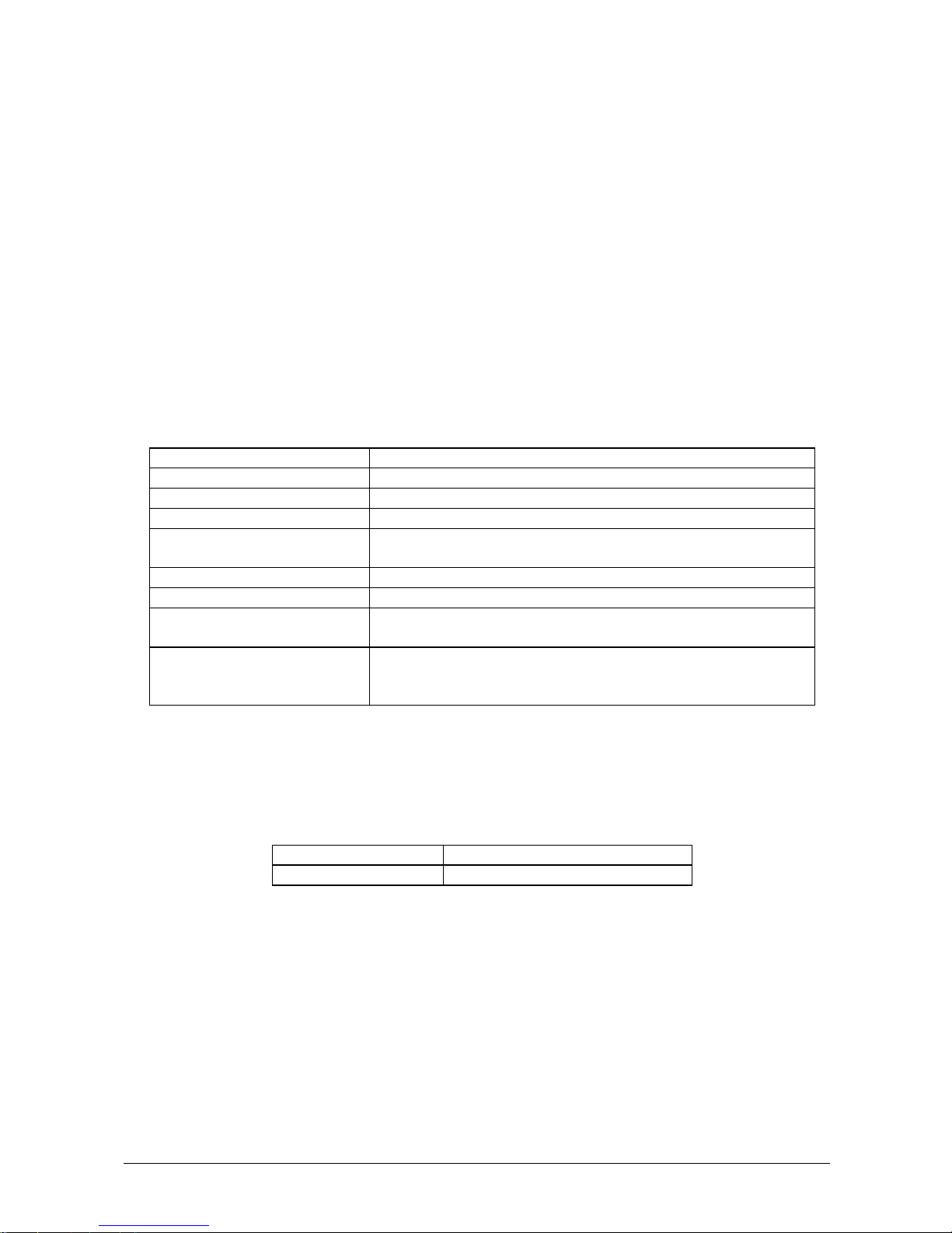
USE In a covered and dry place
DEGREE OF POLLUTION* 2
INSULATION CLASS* I
INSTALLATION CATEGORY* II
TEMPERATURE
Between 18 - 32°C for use
Between 5 - 50°C for storage
HUMIDITY 20% - 85%
ALTITUDE Max 3000 m
LOCATION
Shelf or table with a minimum surface of 70 x 60 cm, stable and free of
vibration
VENTILATION
Leave a minimum distance of 10 cm around the instrument to permit
air circulation. Make sure that the fan (situated under the reagent
compartment) is not blocked by any object.
* Isolation and Safety Standards for Electronic Instruments
1.2.2 ELECTRIC CURRENT REQUIREMENTS
The power voltages that are suited for the instrument are indicated on the back label.
It must be plugged into a plug of the correct voltage.
VOLTAGE 100 - 230 VAC 47/63 Hz ± 10%
FUSES 5 x 20 6.3 A/
T
Note: It is advisable to maintain maximum stability of the electrical current in the laboratory. Where this is not
possible or ascertainable, use of the following supplementary devices is recommended:
1. Electronic Stabilizer
This is used to stabilize the electric voltage in the laboratory. Any stabilizer, currently available on the market,
with a power potential of at least 0.5 KW can be used.
2. No Break module UPS - (Uninterrupted Power Supply)
This module provides two important functions:
- Stabilizes the main-line power
- Supplies current to the instrument in case of a main-line power failure
Page 8
Chapter 01 - INSTALLATION
CYANExpert 130 User Manual Rev.02, Feb 2014 Chapter 1, Page 5
1.2.3 LABEL AND SYMBOLS
1.2.3.1 Label
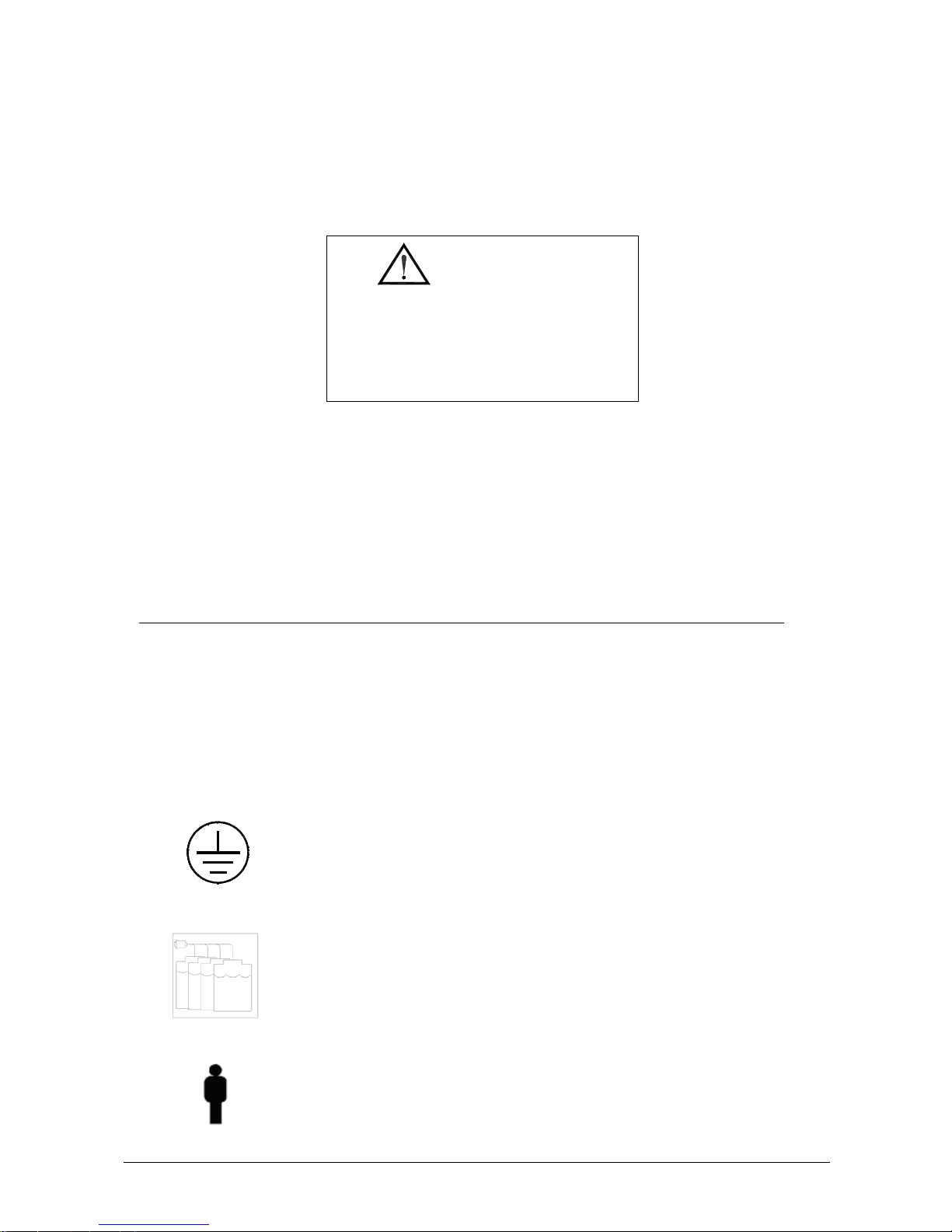
The following LABEL is found at the back of the instrument.
CAUTION
SERVICE PERSONNEL
REFER SERVING TO QUALIFIED
DO NOT REMOVE BACK PANEL.
TO PREVENT ELECTRIC SHOCK
NO USER-SERVICEABLE PARTS INSIDE.
NOTE: The protection cover of the instrument must never be opened without having first switched the
instrument off and disconnected the electricity cable.
The maintenance and cleaning procedures found in chapter 7 of this manual must be respected at all times.
Remember to follow the decontamination procedure when required before maintenance operation (chapter 7).
1.2.3.2 Symbols
Symbol Explanation
Attention:
Read the instructions in the user manual.
Biological hazard:
Carefully manipulate all the consumables and the wastes produced during the
analysis routines. Use appropriate protective garment. Disposal of wastes must
be done in compliance with applicable regulation. It is recommended to
periodically check the level in the waste container, in order to avoid overflow.
Ground terminal (conductor)
Wash bottles connection
I Rinse Solution
II Distilled water
III Cleaning Solution
IV Acid Solution
Stand-by button
Page 9
Chapter 01 - INSTALLATION
CYANExpert 130 User Manual Rev.02, Feb 2014 Chapter 1, Page 6
Buzzer off button
Barcode reader button
1.2.4 R
EGULATORY COMPLIANCE
The CYANExpert 130 complies with European Directive 98/79/CE for
In Vitro
Diagnostic Devices.
1.2.5 LIMITATIONS OF USE
The CYANExpert 130 cannot be used by blind operators because the user interface with the system requires a
monitor.
Furthermore the CYANExpert 130 must be used with particular caution by color blind operators because the graphic
interface displays different colors with different meaning.
1.2.6 BARCODE READER
A barcode reader can be optionally installed on the CYANExpert 130. The barcode reader has a laser micro-scanner
classified as Class II laser device. It is compliant with applicable safety regulations.
WARNING: ALWAYS TURN OFF THE INSTRUMENT before removal of those panels and covers that protect from any
interference and/or exposure to the laser beam active during sample/reagent identification.
1.2.7 CONSUMABLES AND ACCESSORIES SUBJECTED TO WEAR AND USE
These consumables and accessories are not included in the warranty.
Description
Quantity
(Pieces)
Code
Reagents containers - 35 mL + caps 12 CY008-C25
Reagents containers - 6 mL + caps 12 CY008-C26
Reagent tray cover 1 CY008-C08
Reagent tray (without cover) 1 CY008-C09
Reaction cuvettes (20 pcs per sector/rack) 6 CY008-C27
Reaction cuvettes cover 1 CY008-C03
Rack for primary tubes and 3 mL cups 1 CY008-C02
Rack for predilution cups (0.8 mL cups) 1 CY008-C04
Predilution cups (0.8 mL) 1000 CY008-C21
Sample cups for primary tube rack (3 mL) 1000 CY008-C28
Page 10

Chapter 01 - INSTALLATION
CYANExpert 130 User Manual Rev.02, Feb 2014 Chapter 1, Page 7
Short cups – Calibrator and control cups (1 mL) 1000 CY008-C22
Tubing kit for peristaltic pump 2 CY008-C10
Tubing kit – complete 1 CY008-C11
Sampling probe (internal cannula) 1 CY008-S30
Sampling probe assembly 1 CY008-S33
Rinse solution (1 x 50 mL) 1 CY008-WS-I
Acid solution (5 x 25 mL) 1 CY008-WS-III
Cleaning solution (5 x 30 mL) 1 CY008-WS-IV
Drying pad 1 CY008-C01
Halogen lamp (6 V - 10 W) 1 CY008-C20
Fuses 6,3 A-T (5x20) 10 CY008-S09
Inlet/outlet fitting for washing solutions 1 CY008-S75
Bottle 2 L 1 CY008-S77
Bottle level sensor assembly 1 CY008-S76
Washing station, first or second cannulas (A) 1 CY008-S46
Washing station, third cannula (B) 1 CY008-S47
Washing station, fourth cannula (C) 1 CY008-S48
Washing station, fifth cannula without drying pad (D) 1 CY008-S49
Diluter Micro-Pump assembly 1 CY008-S40
Micro-Pump assembly (μP 2 to 5) 1 CY008-S54
Air Micro-Pump assembly (μP 6) 1 CY008-S55
Solenoid Valve –2 way 1 CY008-S58
Solenoid Valve –3 way 1 CY008-S59
Interferential filters kit (Stablife) 1 CY008-S64
Page 11

Chapter 01 - INSTALLATION
CYANExpert 130 User Manual Rev.02, Feb 2014 Chapter 1, Page 8
1.3 BRIEF INSTALLATION PROCEDURE
The installation of the CYANExpert 130 instrument should be performed by a qualified service engineer!
1.3.1 SOFTWARE INSTALLATION
By service engineer
1.3.2 ACCESSORIES CONNECTIONS
Please follow these instructions carefully in order not to damage any parts of the instruments.
1.3.2.1 Power supply
Connect the power cord to a grounded AC wall outlet, preferably one that is not shared with other electric
appliances and with low fluctuation of line voltage compared to the standard voltage specified (10-15%).
If the AC wall outlet is not properly grounded, please connect a ground or earth wire to the mounting screw or
ground terminal (conductor) on the case (see picture above on the right) to ensure safety.
Keep the instrument away from other appliances that generate high frequency electrical noises (eg radiological
instruments).
Note:
The instrument can work at 100 – 230 V. The correct voltage setting is automatically detected and selected by the
apparatus.
!! WARNING !! Fire hazard. For continued protection replace only with the same type and rating of fuses! Fuses
6.3 A/T – 5 X20 ~100-230 V. Always disconnect power cord before opening.
1.3.2.2 Computer connection
The instrument and Personal Computer are connected by a serial RS232 cable (CY008-S78), which provides the
hardware support for the communication.
1.3.2.3
Mounting screw
or ground terminal
Page 12
Chapter 01 - INSTALLATION
CYANExpert 130 User Manual Rev.02, Feb 2014 Chapter 1, Page 9
1.3.2.3 Hydraulic Connections
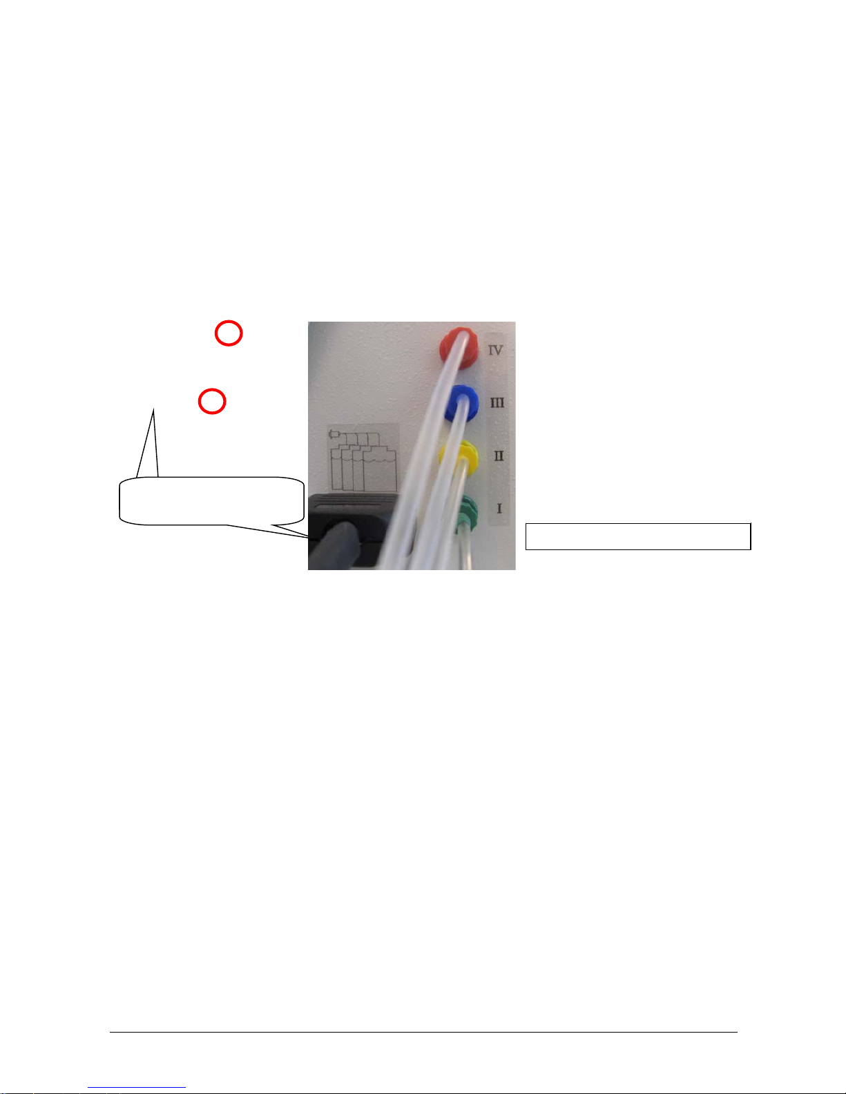
The instrument uses cleaning solution, acid solution and distilled water for cleaning the reaction cuvettes; and rinse
solution for cleaning the sampling probe and determining the cuvette blank level (WBL).
For connecting these solutions, there are four inlets on the side of the instrument identified by roman numbers as
specified here below (see middle picture).
I Rinse solution (CY008-WS-I) green color
II Distilled water yellow color
III Cleaning solution (CY008-WS-III) blue color
IV Acid solution (CY008-WS-IV) red color
Connect the bottles interconnecting cable between the four wash solution bottles and the instrument. This way the
level of the solutions can be measured and controlled. Please ensure to connect the correct cable to the correct wash
bottle and sensor (roman numbers) (see picture above on left).
The waste hydraulic lines are located on the back side of the instruments (see picture above on right). Put the three
different waste lines into a waste container, separately or all together, according to the costumers’ site waste
legislation and regulation. Make sure the waste container(s) is standing below the tubes outlet on the analyzer.
1. Biological hazard or biohazard: sample and reagents Silicon tubing Øi2-Øe4
2. Limited biohazard: minimal contact with sample and reagents Silicon tubing Øi2-Øe4
3. No biohazard PVC tubing Øi2-Øe6
1 2 3
Bottles interconnecting
cable
Page 13
Chapter 01 - INSTALLATION
CYANExpert 130 User Manual Rev.02, Feb 2014 Chapter 1, Page 10
1.3.2.4 Pump Tube Connection
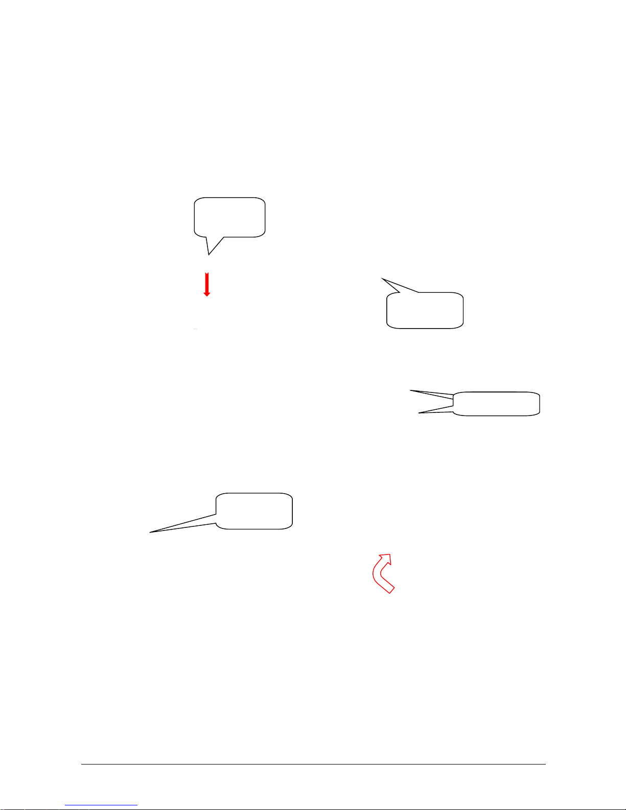
Upon delivery, the pump is in a ‘relaxed’ state: the tube is loose. To make it operational, proceed as follows:
1. Open the peristaltic pumps’ door at the side of the instrument.
2. Hook the hinged guide (picture above), paying attention to the correct position of the tubes. These should
be in the two guides of the holder (picture below).
3. Manually rotate clockwise the peristaltic pump rotor and check to make sure that the tubes are correctly
positioned insides the guides.
4. Close the peristaltic pumps’ door.
Peristaltic
pump door
Unhooked
hinged guide
Two
Two guides
Hooked
hinged guide
Page 14
Chapter 01 - INSTALLATION
CYANExpert 130 User Manual Rev.02, Feb 2014 Chapter 1, Page 11
1.3.2.5 Sample Probe Installation
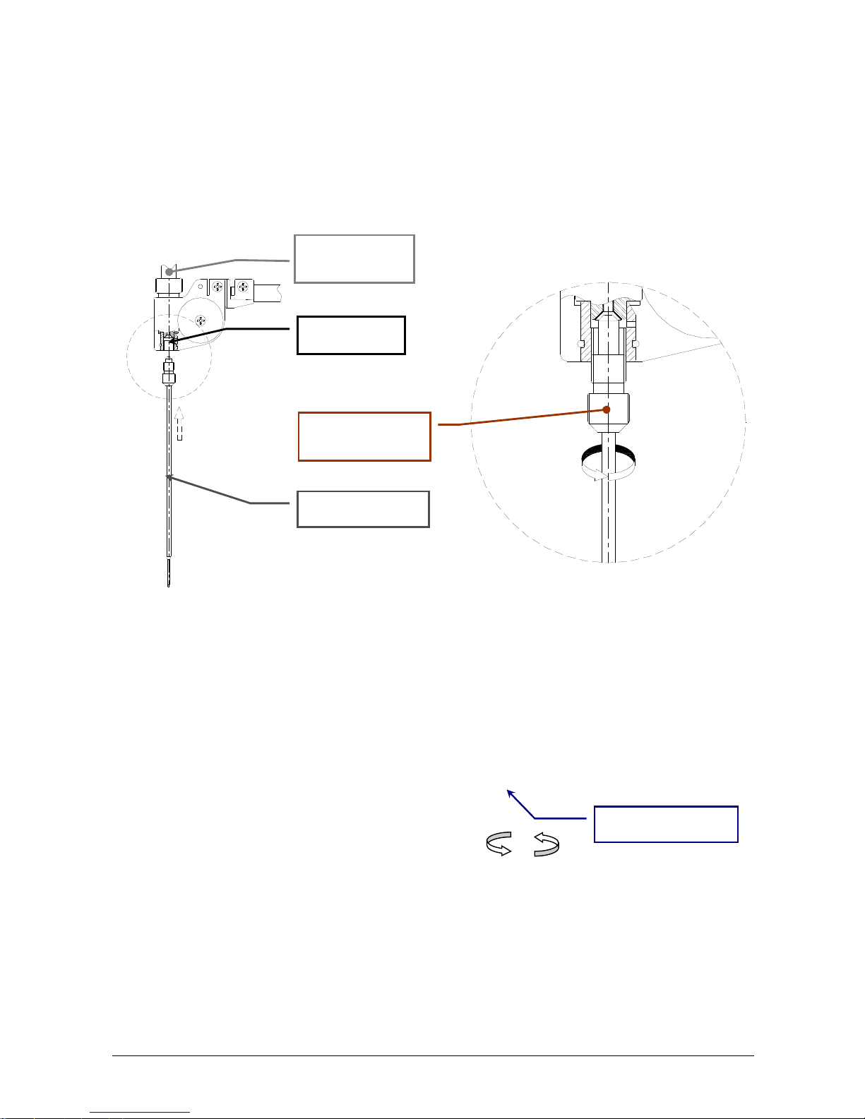
The sample needle is delivered in a small tube to protect the level sensor device. To install this needle, please
proceed as follows:
1. Carefully take out the probe from its protection tube. Do not touch the tip of the probe. This way the liquid
level sensor can be damaged.
2. Please insert (straight!) the sample probe to the probe holder of the sampling arm and slowly rotate
(counter clockwise) the sample probe ring nut (without applying any force!).
3. Take the special screwdriver (dynamometric key), delivered with the instrument, and place the head
around the ring nut of the sample probe (see figure below). Screw (counter clockwise) with the
dynamometric key until the correct torque is reached and the key spins freely around the sample probe. You
will hear a clicking noise when it is screwed completely, do NOT try to screw it any further.
4. Remove the dynamometric key.
5. Open the “Diagnostic” program; select "Miscellaneous” folder and request an Instrument General Reset. Wait
until the general reset procedure has been completed; make sure that all the Home Sensors of the Sampling
Arm (Vertical and Horizontal), Reactions, Reagents and Samples Plates light up in green.
Sample probe
Sampling arm
head
Probe holder
CCW
Sampling probe
ring nut
Dynamometric key
CC
W
Page 15

Chapter 01 - INSTALLATION
CYANExpert 130 User Manual Rev.02, Feb 2014 Chapter 1, Page 12
Pay attention: The needle should be perfectly straight (90° angle to the analyzers platform) onto the sampling arm
and perfectly above the washing well, when it is in its initial position (general reset). If the probe is not positioned
correctly, the level sensor can be damaged once the analyzer is running. If case of doubt about the correct
installation or centering; please always contact your service engineer.
1.3.2.6 Reaction Rack Installation
The analyzer is delivered with six reaction racks (20 reaction cuvettes per rack). These should be placed in the outer
circle of the plate. To install them, please proceed as follows:
1. Turn on the analyzer and wait until the instrument has reached its proper operating temperature.
2. Remove the black reaction rack cover present on the reaction rack area.
3. Push the “load reaction rack’- replace button in the software.
4. Turn the two metal locking pins so that they are in line with the plate or screw the attachment screws.
5. Place the reaction rack in the analyzer. Always insert the racks vertically. Be especially careful not to touch
the external surface of the reaction cuvettes with your fingers. Also check no packaging material
(isomo) is attached to the cuvettes. This latter and fingerprints will have a bad influence on the
measurements.
6. Turn the two metal locking pins back to their original position.
7. Turn the plate by using the “load reaction rack” button in the software interface and perform the same for
the other 5 reaction racks.
Load reaction rack
button
Reaction rack cover
Metal locking pin in
line with the plate
Metal locking pin in
original position
Page 16

Chapter 01 - INSTALLATION
CYANExpert 130 User Manual Rev.02, Feb 2014 Chapter 1, Page 13
1.3.3 CHECKING THE ANALYSER
By service engineer
1.3.4 ADAPTATION OF THE SYSTEM TO THE CUSTOMER
1.3.4.1 Install additional methods (if necessary)
By service engineer
1.3.4.2 Configure the user specific options
- Open the CYANExpert 130 software
- Go to the menu “Parameters” and open the menu “Options” (Chapter 3).
- Indicate the following settings according to the customers’ site:
Barcode reader
Host connection
Type of default reagent container: 6 ml or 35 ml. In this menu the default container is set. The user can still
choose the other container in the menu ‘Checks’ in the submenu ‘Reagent configuration’.
Pay attention: what is programmed in the software should correspond to what is placed on the plate
manually! This is extremely important in order not to break the sample probe!
Type of default cup container: 3 ml or primary tubes. This is extremely important in order not to break
the sample probe! Primary tubes and 3 ml cups can both be placed on a sample rack for primary tubes.
Using the setting primary tubes is safe for primary tubes and 3 ml tubes; however it increases the dead
volume for the 3 ml tubes. The setting of 3 ml tubes CANNOT be used for primary tubes!
A combination of different sample cup settings is NOT possible! The user has to choose the same
option for the 4 racks!!
Automatic data deletion (number of days)
In order to protect the sampling probe and its level sensor, always make sure the programmed type of sample
cups and reagent containers in the option folder and on the software configuration of the plate are
completely the same as the real cups and containers putted on the plate by the user! This should be made
very clear to the user, so please repeat it several times, theoretically and practically!
1.3.4.3 Create user profiles
Give the user(s) restricted access by creating user profiles.
The first time they login, they have the opportunity to change the password to their choice.
1.3.5 GIVE EXTENSIVE EXPLANATION TO THE USER!
Explain the procedure for routine analysis (patient entries, patient results, calibration results, QC-results – for more
information see quick user manual). Teach them how to run the tests and check the results. Always do some tests
together with the customer in order to teach them how to use the CYANExpert 130!
In order to protect the sampling probe and its level sensor, always make sure the programmed type of sample
cups and reagent containers in the option folder and on the software configuration of the plate are
completely the same as the real cups and containers put on the plate by the user! This should be made very
clear to the user, so please repeat it several times, theoretically and practically!
Page 17

Chapter 02 - GENERAL DESCRIPTION
CYANExpert 130 User Manual Rev.02, Feb 2014 Chapter 2, Page 1
CHAPTER 02 – GENERAL DESCRIPTION
2.1 INTENDED USE AND SYSTEM DESCRIPTION ........................................................................... 2
2.2 MAIN COMPONENTS and ANALYSE CYCLES ........................................................................... 3
2.2.1 ANALYTICAL PLATE ................................................................................................................................... 3
2.2.2 WASHING WELL ........................................................................................................................................ 4
2.2.3 SAMPLING SYSTEM ................................................................................................................................... 4
2.2.4 SAMPLING ARM ......................................................................................................................................... 5
2.2.5 WASHING STATION ................................................................................................................................... 7
2.2.6 INCUBATOR ................................................................................................................................................ 8
2.2.7 PERISTALTIC PUMP ................................................................................................................................... 8
2.2.8 PHOTOMETRIC SYSTEM ............................................................................................................................ 8
2.2.9 FRONT PANEL INDICATION BUTTONS ....................................................................................................... 8
2.2.10 BARCODE READER .................................................................................................................................... 8
2.3 SOFTWARE AND COMPUTER SPECIFICATIONS ...................................................................... 9
2.4 TECHNICAL & OPERATIVE FEATURES ........................................................................................ 9
2.5 DIMENSION, WEIGHT and ENVIRONMENT ............................................................................ 10
2.6 INSTALLATION SPECIFICATIONS ............................................................................................. 10
Page 18

Chapter 02 - GENERAL DESCRIPTION
CYANExpert 130 User Manual Rev.02, Feb 2014 Chapter 2, Page 2
2.1 INTENDED USE AND SYSTEM DESCRIPTION
The CYANExpert 130 is a random access, computer controlled, bench top, clinical analysis instrument. The system
can perform 138 tests per hour and has a machine cycle of 26 seconds. Its execution time ranges from a minimum of
18 seconds to a maximum of 1032 seconds, depending on the analysis method chosen.
At installation of the system, the service engineer must configure the system based on the specific needs of the
user. The service engineer must program the chemistry method parameters, the reagents configuration racks, the
normal value ranges for samples, calibrators and controls, the options, the print report and make user accounts.
The daily routine analysis can be carried out according to patient sample arrival in a sequential and continuous,
non-stop manner.
The work list is organized by loading racks that can hold up to 8 patient samples per rack. Racks can be loaded
continuously. The racks can accommodate primary tubes or 3mL cups. Racks for predilution cups (0.8 mL) are
optional. The barcode reader for primary tubes and reagent containers is an optional feature.
If the analytical unit (and the computer) is turned on, the instrument goes in “Stand-by” status:
The lamp is supplied with low voltage power (1.2 V)
The reaction plate is maintained at 37°C
The electronic components are turned on
The sampling arm pre-heater remains turned off
The "Stand-by" light, placed on the front panel, will flash until the reaction plate reaches a temperature of 37°C.
Once it is reached, the "Stand-by" light will stop flashing and will remain constantly lit.
When any system function or measurement is launched:
The lamp is supplied with regular voltage power (6.0 V)
The sampling arm pre-heater will warm up
In the case of system failure or malfunction, the light, situated on the front panel of the instrument, will light up red.
When starting up the computer, the software should automatically open. Otherwise, double click on the
“CYANExpert 130" icon on the computer desktop. The login menu will appear.
NOTE:
The CYANExpert 130 is a system that allows configuration with different reagents selected by the customer in order
to fit his needs. Upon delivery, the instrument is configured for the validated biochemistry kits of Cypress
Diagnostics. In order to assure the analytical performances of the system “instrument + reagents”, we strongly
recommend only to use reagents, controls and calibrators validated on the CYANExpert 130.
Page 19
Chapter 02 - GENERAL DESCRIPTION
CYANExpert 130 User Manual Rev.02, Feb 2014 Chapter 2, Page 3
2.2 MAIN COMPONENTS and ANALYSE CYCLES
2.2.1 ANALYTICAL PLATE
The analytical plate is the main movable part of the analyser and is built up out of three plates, each separately
moving from each other due to three different axes.
From the outer to the inner circle it contains:
The REACTION PLATE, provided with 6 semi-disposable racks of 20 reaction cuvettes, for a total of 120
cuvettes.
The SAMPLE PLATE, provided with 4 sample racks of 8 sample positions each, for a total of 32 samples. You
can program and use either primary tubes (universal) or 3 mL sample cups. For every sample, there is also a
position for a predilution cup (0.8 mL).
The REAGENT AND CALIBRATOR/CONTROL PLATE, provided with 12 calibrator and control positions (1 mL
cups) and 24 reagent positions. You can program and use 35 mL or 6 mL reagent containers.
A. REACTION PLATE
DESCRIPTION:
The reaction plate of the CYANExpert 130 contains 6 semi-disposable racks with 20 reaction cuvettes each.
The racks can be removed individually. However, it is recommended to replace them together.
The basic operating cycle of the reaction plate takes 26 seconds. This cycle includes the optic reading of the
cuvettes in incubation, the aspiration and dispensation of the reagents and the samples by the arm, along with the
relative positioning of the plate.
The reactions take place at 37°C. This temperature is maintained constant by a controlled heating unit placed under
the reaction plate.
REACTION PLATE CYCLE:
After reagents and samples have been placed in cuvette #1, the reaction plate will rotate 40 positions counterclockwise to bring this first cuvette in front of the optic system for reading with either one or two wavelengths.
The plate will then, moving clockwise, carry out all the readings of any other prepared cuvettes. After having
performed all the readings, the plate will move counter-clockwise to its initial position minus one cuvette, ready for
a new dispensing.
In this manner, the reaction cuvettes move clockwise 1 - 2 - 3 - 4 for dispensation, washing and the relative readings.
REACTION PLATE
with reaction cuvettes
CALIBRATOR/CONTROL
AND REAGENT PLATE
SAMPLE PLATE
Primary tubes
3mL cups
Predilution cups
Reagent container 35
mL or 6 mL
Calibrator or control
cups (1 mL)
Page 20

Chapter 02 - GENERAL DESCRIPTION
CYANExpert 130 User Manual Rev.02, Feb 2014 Chapter 2, Page 4
B. SAMPLE PLATE
DESCRIPTION:
The sample plate is provided with 4 removable racks of 8 sample positions each. This makes a total of 32 sample
positions on one cycle. Sample racks can be continuously loaded during running.
The CYANExpert 130 is delivered with 4 racks for primary tubes. They each contain 8 sample positions and 8
corresponding predilution positions. This rack can be used with primary tubes and 3 ml cups.
Pay attention!
Primary tubes dimensions: diameter from 8 to 16 mm, height from 40 to 100 mm.
Never use 1 mL cups on the primary tube rack!
Remark: The predilution position (0.8 mL cups) is only used for methods that require a predilution for all the
samples. The predilution ratio and the necessary diluent are then programmed in the method parameters menu.
Pay attention! Dilution of ‘rerun’-samples is done automatically in the reaction cuvettes and does not use these
predilution positions.
Optionally, they are racks for predilution available. These contain 25 positions for 0.8 ml cups.
This rack is used for:
- Automatic calibration dilution for multipoint calibrations (e.g. Turbidimetric measurements)
- Predilution of calibrators and controls of methods that are programmed with a predilution
- Repetition of samples for methods programmed with a predilution and for which the predilution position
on the sample rack has already been used.
The CYANExpert 130 allows to program zero, one or two predilution racks.
The predilution racks are not standardly included. They have to be ordered separately.
C.
REAGENT AND CALIBRATOR/CONTROL PLATE
DESCRIPTION:
The reagent and calibrator/control plate is a non-cooled, removable tray with 24 positions for reagents (35 ml or 6
ml containers) and 12 positions for calibrators and controls (1ml cups). This tray can be easily removed for
refrigeration. During analysis, the tray must always be protected by the reagents plate cover. Only this way external
contamination can be avoided. The cover must be fixed by turning the upper black handle clockwise.
2.2.2 WASHING WELL
The washing well is the place where the washing of the sampling probe (internally and externally) with rinse
solution takes place to avoid cross-contamination between sampling.
2.2.3 SAMPLING SYSTEM
The sampling system consists of a highly precise diluter controlled by a microprocessor and has the following
specifications:
Diluter volume 550 µl
Sample volume from 2 to 99 µl with 1 µl increment
Reagent 1 volume
Reagent 2 volume
Reagent 3 volume
from 3 to 500 µl with 1 µl increment
from 3 to 330 µl with 1 µl increment
from 3 to 330 µl with 1 µl increment
Minimum reaction volume 220 µl
Accuracy >99%
Materials in contact with the solutions
T
eflon & glass
Precision CV < 1 % at 2 l
The recommended minimum sampling volume is 3 l and 250 l for total reaction volume. There is also an
automatic wash cycle in between tests to avoid the risk of cross-contamination.
Page 21
Chapter 02 - GENERAL DESCRIPTION
CYANExpert 130 User Manual Rev.02, Feb 2014 Chapter 2, Page 5
2.2.4 SAMPLING ARM
DESCRIPTION:
The sampling arm aspirates the reagent and sample to be analysed and dispenses them into the reaction cuvette
for incubation and reading. It can also fill the reaction cuvettes with rinse solution to check the performance of the
system.
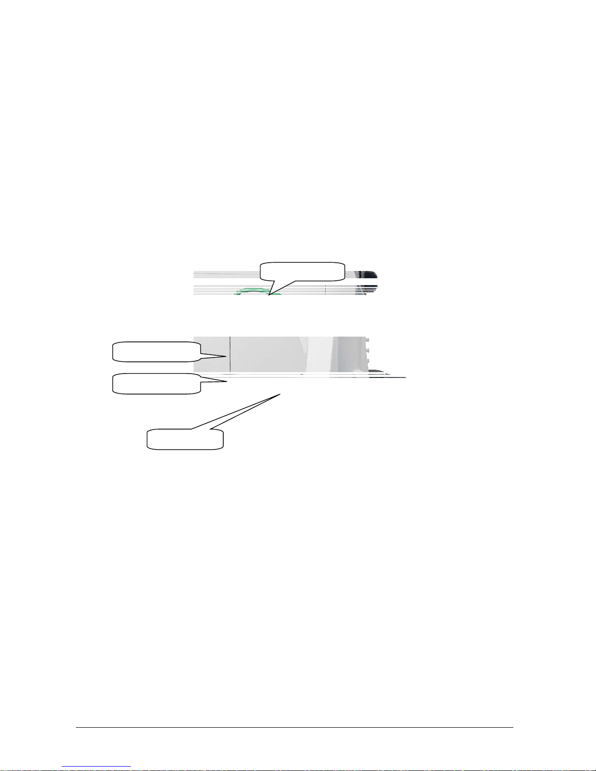
The sampling arm contains the following parts:
Sample probe with level sensor. This part is very fragile, please handle with care.
Preheater line (green isolated wire on top of the arm) to heat the sample and reagent in the sampling line
up to 37°C before dispensing them into the reaction cuvettes. When heated, the part is very fragile and can
easily break. Never touch it before it has cooled down.
Vertical arm with a vertical and horizontal sensor and motor, making it able to be positioned correctly
relative to the washing well and the three analytical plates, without breaking the probe and its level sensor.
OPERATIONAL SEQUENCE:
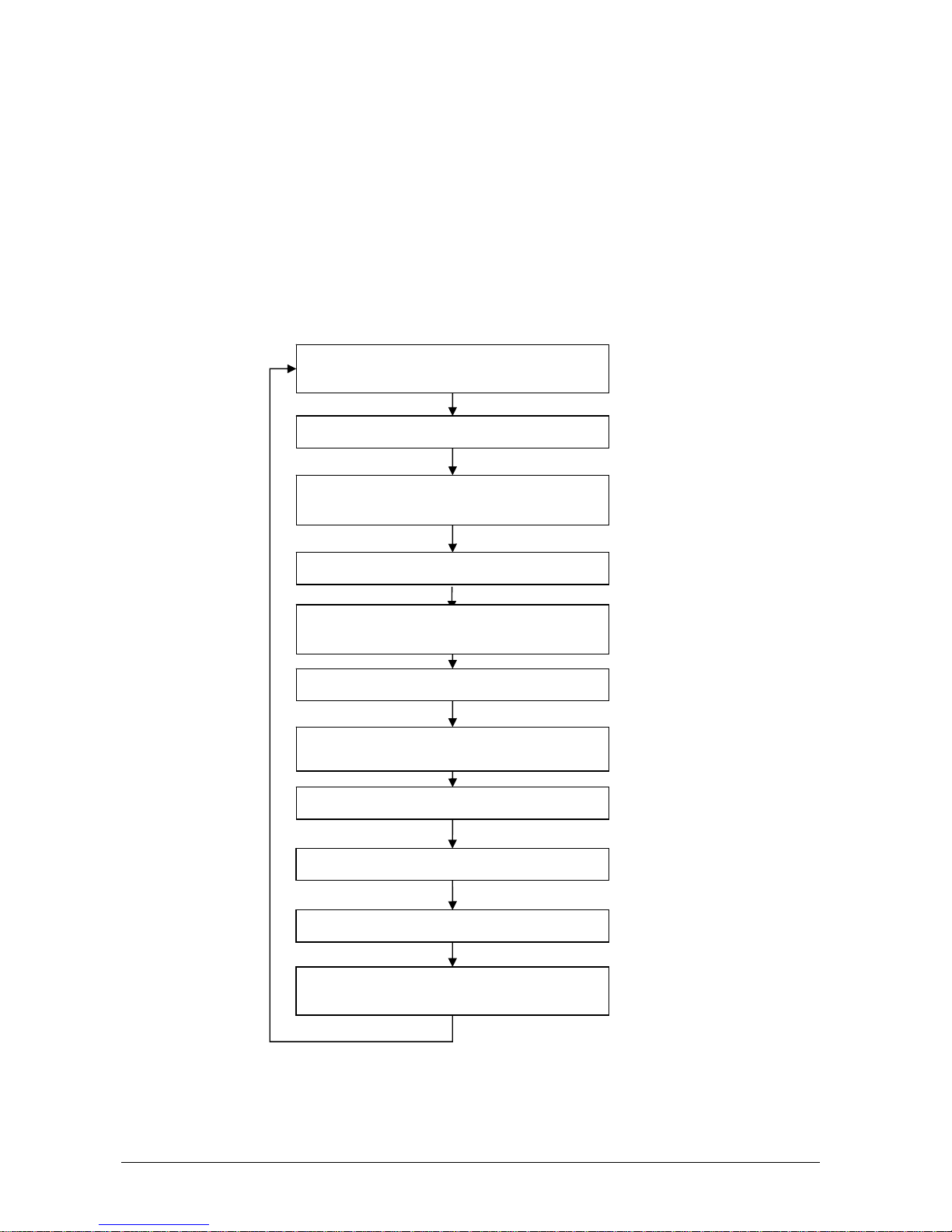
1. The sampling arm lifts up from the washing well and carries out a wash cycle with rinse solution;
2. The arm moves toward the specific reagent container, while the diluter aspirates an air bubble to separate
the rinse solution from the reagent;
3. The arm lowers itself into the reagent, below the level indicated by the sensor, and aspirates the required
quantity of reagent. If the method requires a ‘rinse’ (programmed in the method and used in order to
reduce the possibility of negative contamination between the aqueous rinse solution and the reagent) an
extra amount of reagent (not used in the analysis) will be aspirated before the quantity of reagent
necessary for the analysis, along with another air bubble for their separation;
4. While the arm rises, the diluter aspirates a second air bubble to prevent reagent loss, and then lowers into
the washing well so that it can be washed externally, to minimize cross contamination;
5. The arm is raised from the washing well and moves to the specified sample while aspirating a third air
bubble;
6. Once the level sensor detects the presence of liquid, the arm stops and aspirates the sample;
Washing well
Sampling probe
Level sensor
Preheater line
Page 22
Chapter 02 - GENERAL DESCRIPTION
CYANExpert 130 User Manual Rev.02, Feb 2014 Chapter 2, Page 6
7. While the arm is raised once again, the diluter aspirates a fourth air bubble to prevent sample loss;
8. At this point, the arm returns to the washing well in order to clean the outside of the probe and, thereafter,
aspirates a fifth air bubble;
9. The arm moves to the reaction plate, dispenses, and mixes the reagent and sample in the reaction cuvette
for incubation and reading;
10. The arm returns to the washing well and carries out a probe wash cycle to wash the probe internally with
rinse solution.
SCHEMATIC DRAWING:
Aspiration of Air
(To separate rinse solution from reagent)
Aspiration of Reagent
Aspiration of Air
(To prevent reagent loss)
External probe cleaning above washing well
Aspiration of Air
(To prevent contamination of the sample)
Aspiration of Sample
Aspiration of Air
(To prevent sample loss)
External probe cleaning above washing well
Aspiration of Air
Dispensing and mixing in cuvette
External and internal probe cleaning above
washing well with rinse solution
Page 23
Chapter 02 - GENERAL DESCRIPTION
CYANExpert 130 User Manual Rev.02, Feb 2014 Chapter 2, Page 7
2.2.5 WASHING STATION
DESCRIPTION:
The reaction plate washing station is made up of a series of five small needles situated on one side of the reaction
plate. These needles are connected to the valve and pump system on the rear panel of the instrument for
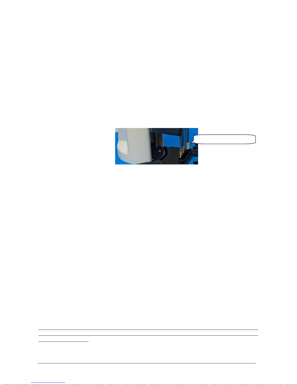
automatically emptying, washing and drying the reaction cuvettes. The first, second and third needle are composed
of an internal and an external cannula, to empty and refill the reaction cuvette with respectively acid solution,
cleaning solution and distilled water for washing. The fourth needle will empty the reaction cuvette after the checkup reading with the distilled water. The fifth cannula contains a dryer pad to remove any residual liquid drops.
To wash the reaction racks the wash station uses three different reagents that are indicated as follows:
II Distilled water (yellow color)
III Cleaning solution (blue color)
IV Acid solution (red color)
WASHING STATION CYCLE:
The washing cycle is started when all the programmed samples are dispensed or when half of the available reaction
cuvettes are full. The wash station carries out its operations alternating an upward and downward movement into
the reaction cuvettes:
1. The first needle first removes the reaction mix, using the internal cannula. Then the external cannula dispenses,
in a shower-like fashion, acid solution to wash the cuvette. This solution is then aspirated again to the waste
through the internal cannula. This washing cycle is performed twice with 300 µl.
2. The second needle operates identical as the first but using cleaning solution.
3. The third needle performs two aspiration and dispensation cycles with distilled water, exactly like the first two
needles. However, in the 3e cycle, the external cannula dispenses 400 µl distilled water into the cuvette to
perform an optical measurement (WBL) to check whether the cuvette can be reused for a new measurement. If
the results are negative, the cuvette is discarded and indicated in red on the software interface.
4. The fourth needle aspirates the distilled water used for the optic check.
5. The fifth needle dries the sides.
All these operations are part of the routine operation of the instrument. Every reaction cuvette is washed at the end
of each round of analysis and the reusability (optical integrity) of each reaction cuvette is also tested, thus before
the next round of analysis.
Drying pad on cannula 5
Page 24

Chapter 02 - GENERAL DESCRIPTION
CYANExpert 130 User Manual Rev.02, Feb 2014 Chapter 2, Page 8
2.2.6 INCUBATOR
The incubation temperature of the reaction cells is fixed at 37°C ( 0,2°C) to ensure proper incubation for all
samples. Mixtures of sample and reagent are heated up to 37°C with the preheater on the sampling arm module.
The incubator on the reaction plate is used to maintain this 37°C.
2.2.7 PERISTALTIC PUMP
The two-channel-peristaltic pump is only used for the aspiration of the first and second needle of the washing
station to empty the cuvettes. The other aspirations and all dispensations are driven by small micro-pumps (please
see the hydraulic diagram in the service manual).
2.2.8 PHOTOMETRIC SYSTEM
The optical system contains a filter wheel with 10 positions: one dark filter, eight interferential filters (340 nm, 380
nm, 405 nm, 492 nm, 510 nm, 546 nm, 576 nm and 620 nm) and one total light position.
The other characteristics of the optical system are as follows:
Absorbance range 0.0005 - 3.500 O.D.
Resolution 0.0005 O.D.
Accuracy
0.001 O.D.
Light source 6V-10W halogen lamp, double beam
Detector Silicon photodiode
Zeroing Automatic, computer controlled
Light path 6 mm
2.2.9 FRONT PANEL INDICATION BUTTONS
The front panel of the analyser contains three indication buttons:
Yellow: to turn off the alarm in case of a warning.
Green: to indicate the standy-by status. This lamp is flickering as long as 37°C is not reached on the
reaction plate.
Red: flickers when the instrument is running and in case of barcode readings.
2.2.10 BARCODE READER
Reading samples and reagent with a barcode reader is an optional feature.
Page 25

Chapter 02 - GENERAL DESCRIPTION
CYANExpert 130 User Manual Rev.02, Feb 2014 Chapter 2, Page 9
2.3 SOFTWARE AND COMPUTER SPECIFICATIONS
Minimum requirements:
Type: IBM Compatible
CPU: Pentium IV 500 MHz - 512 Kb Cache or plus
Memory: RAM 256 MB or plus
Hard Disk: 20 GB or plus
CD ROM: 24X for installation
Video Memory 4 MB
Monitor: SVGA 15’’ color; low radiation – Resolution: 800 X 600 pixels
max number of colors: 65536 (16 bit)
Printer: Windows compatible, 80 Columns impact graphic
Keyboard & Mouse: Standard Keyboard 101 keys – PS2
Interface: One Bi-directional RS 232C serial port or USB A port if RS233-USB converter cable
is used
One parallel (one second serial port for the Host link) serial port
Software: Multitasking Windows XP and Windows Vista and Windows 7
Settings: Disable all the energy saving options
Disable the screen saver
Select English “USA” as language
Dot as decimal symbol
Correct date and time in Regional settings
NOTE: Even though the computers demonstrate the same technical and operative characteristics, some of these
could have different hardware installed. This could cause problems for the CYANExpert 130- software when
running tests (‘Random’ error or blocking of the program). Please contact your local distributor in case of
any problems.
2.4 TECHNICAL & OPERATIVE FEATURES
Resume of main technical features:
Assay Type: End Point, Differential, Initial Rate (or Fixed Time), Kinetics and Bichromatic
methods
Test Selection Mode Random, Continuous loading
Throughput 138 test/h
Working Temperature
37C
On Line Reagents 24 Reagents (35 ml and 6 ml)
Calibrators & Controls one rack for 12 calibrators and controls
Sample loading four racks for a total of 32 samples
Min. Reaction Volume 220 l
Max. Reaction Volume 550 µl
Sampling Arm Aspiration and dispensation of reagent and sample; probe washing
Page 26

Chapter 02 - GENERAL DESCRIPTION
CYANExpert 130 User Manual Rev.02, Feb 2014 Chapter 2, Page 10
Diluter Integrated module with the following specifications:
Sample volume: 2.0 l - 99 l (1 l incr.)
Reagent volume: 3.0 l - 500 l (1 l incr.)
Reaction Plate Six sectors of 20 reaction cuvettes for a total of 120 cuvettes
Washing station Automatic washing of the reaction cuvettes
Optic System
Photometer multi wavelength photometer with narrow band interferential filters
Wavelength 340 nm, 380 nm, 405 nm, 492 nm, 510 nm, 546 nm, 578 nm and 620 nm
Light source halogen lamp 6V/10 W, double beam
Linear range 0.0005 - 3.500 Abs
Resolution 0.0005 Abs
Detector Silicon photodiode
Reaction cuvette Optical Path : 6 mm
2.5 DIMENSION, WEIGHT and ENVIRONMENT
Dimension
Height: 53 cm
Width: 57 cm
Length: 75 cm.
Weight: 35 Kg.
Environment:
Temperature: 18°C - 30C
Relative humidity: 20% - 85%
2.6 INSTALLATION SPECIFICATIONS
The following is required for the power supply specifications:
Input voltage: 100 ÷ 230 Vac
Input frequency: 47 ÷ 63 Hz
Power consumption:
o 300 W for the analysis unit
o 400 W for the work station
Warning: in order to assure proper instrument functioning, the manufacturer strongly advises the use of a stable
tension supply outlet (+/-10%). If it is not possible to guarantee this stability, the manufacturer suggests the use of:
Electronic Stabilizer
This is used to stabilize the electric voltage in the laboratory. Any stabilizer with a power potential of at
least 1KW, currently available on the market, can be used.
No Break module UPS - (Uninterrupted Power Supply)
This module provides two important functions:
- stabilizes the main-line power
- supplies current to the instrument in case of a main-line power failure
Page 27

Chapter 03 – SOFTWARE DESCRIPTION
CYANExpert 130 User Manual Rev.02, May 2014 Chapter 3, Pag e 1
CHAPTER 03 – SOFTWARE DESCRIPTION
3.1 SYSTEM MONITOR ........................................................................................................................ 3
3.1.1 M
AIN TASKBAR .............................................................................................................................................................. 4
3.1.2 D
ESK TOP ....................................................................................................................................................................... 4
3.1.3 V
IEW DATA/DETAILS AREA .......................................................................................................................................... 5
3.1.4 L
EGEND .......................................................................................................................................................................... 6
3.1.5 C
OMMAND BUTTONS .................................................................................................................................................... 7
3.1.6 O
PERATIVE BUTTONS .................................................................................................................................................. 11
3.1.7 W
ARNING LIGHTS ........................................................................................................................................................ 13
3.1.8 D
IAGNOSTIC & STATUS BAR ....................................................................................................................................... 13
3.2 START WORK ................................................................................................................................ 14
3.2.1 W
ASH CUVETTES ......................................................................................................................................................... 14
3.2.2 W
ATER BLANK LEVEL .................................................................................................................................................. 14
3.2.3 P
REDILUTION RACK(S) REPLACED .............................................................................................................................. 15
3.2.4 C
ALIBRATION & Q.C. .................................................................................................................................................. 15
3.2.5 W
ORK LIST ................................................................................................................................................................... 15
3.2.6 S
TART RUNNING .......................................................................................................................................................... 15
3.3 OPERATIONAL MENU (MAIN TASKBAR) ................................................................................. 16
3.4 CHECKS ......................................................................................................................................... 16
3.4.1 W
ATER BLANK LEVEL (WBL) ..................................................................................................................................... 17
3.4.2 R
EAGENTS VOLUME .................................................................................................................................................... 18
3.4.3 R
EAGENTS CONFIGURATION ...................................................................................................................................... 20
3.4.4 P
REDILUTION ............................................................................................................................................................... 22
3.5 ROUTINE ........................................................................................................................................ 23
3.5.1 W
ORK LIST SETUP ....................................................................................................................................................... 23
3.5.2 R
ESULT BY PATIENT .................................................................................................................................................... 30
3.5.3 R
ESULT BY TEST ........................................................................................................................................................... 32
3.5.4 C
ALIBRATION & QUALITY CONTROL SETUPS ............................................................................................................ 33
3.5.5 C
ALIBRATION RESULTS ............................................................................................................................................... 37
3.5.6 Q
UALITY CONTROL RESULTS ...................................................................................................................................... 41
3.5.7 R
ECEIVE FROM HOST ................................................................................................................................................... 43
3.6 ARCHIVE ........................................................................................................................................ 44
3.6.1 P
ATIENTS ...................................................................................................................................................................... 44
3.6.2 C
ALIBRATION ............................................................................................................................................................... 46
3.6.3 B
ACKUP ........................................................................................................................................................................ 48
Page 28

Chapter 03 – SOFTWARE DESCRIPTION
CYANExpert 130 User Manual Rev.02, May 2014 Chapter 3, Pag e 2
3.6.4 RESTORE ....................................................................................................................................................................... 48
3.6.5 T
EST COUNTER ............................................................................................................................................................ 49
3.6.6 E
VENT LOG ................................................................................................................................................................... 50
3.6.7 A
DMIN LOGS ............................................................................................................................................................... 50
3.7 PARAMETERS ............................................................................................................................... 51
3.7.1 R
EAGENTS ID ............................................................................................................................................................... 51
3.7.2 P
ROFILES ...................................................................................................................................................................... 52
3.7.3 R
ATIO ........................................................................................................................................................................... 54
3.7.4 C
ALIBRATORS ............................................................................................................................................................... 56
3.7.5 C
ONTROLS ................................................................................................................................................................... 60
3.7.6 O
PTIONS ...................................................................................................................................................................... 64
3.7.7 S
AMPLING ORDER ........................................................................................................................................................ 67
3.7.8 P
RINT ORDER ............................................................................................................................................................... 68
3.7.9 R
EPORT OPTIONS ........................................................................................................................................................ 68
3.7.10 A
CCOUNTS ................................................................................................................................................................... 69
3.8 HELP ............................................................................................................................................... 71
3.8.1 G
UIDE .......................................................................................................................................................................... 71
3.8.2 I
NFO .............................................................................................................................................................................. 71
3.9 LOG OFF ........................................................................................................................................ 72
3.10 SHUT DOWN ................................................................................................................................ 73
Page 29
Chapter 03 – SOFTWARE DESCRIPTION
CYANExpert 130 User Manual Rev.02, May 2014 Chapter 3, Pag e 3
1.1 SYSTEM MONITOR
The CYANExpert 130 software is extremely user-friendly and, moreover, allows maximum flexibility in its use.
In order to access the main program, double click on the CYANExpert 130 icon on the computer desktop.
A “Login” window appears, asking for the following specifications:
According to the computers configurations, the software can be opened automatically when turning the PC on
and automatically shut down when closing the software.
Pay attention: The CYANExpert 130 should be linked to a designated PC used only to run the CYANExpert 130
program. It is impossible to run other programs when the analyser is in use.
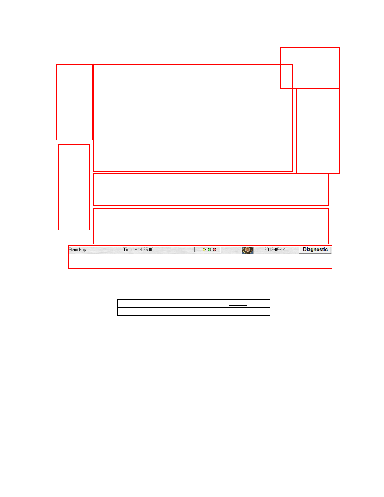
The “System Monitor” interface is sub-divided into the following areas:
1. “Main Taskbar”: contains the following menus: Monitor, Checks, Routine, Archive, Parameters, Help, Log
Off, and Shut down. All these menus are used to control the performance of the analyser, to change
methods and to run samples. More information is given from paragraph 3.3 to 3.10.
2. “Desk Top”: contains the following interfaces: The plate’s configurations: visually: reagent and control
plate, sample plate and reaction plate; and listed: reagent list and calibrator and control list.
3. “View Data/Details Area”: contains detailed information concerning the item selected (sample, reagent,
calibrator and control) or concerning the warnings.
4. “Legend”: indicates the reagent and sample status, the type of containers (reagents and samples) and the
presence/absence of calibrators and controls with different colours.
User Name User identification code (User ID)
Password Access code
1. Main Task Bar
3. View Data/Details Area
6. Operative Buttons
4. Legend
7. Warning Lights
8. Diagnostic & Status Bar
2. Desk Top
5.Command Buttons
Page 30
Chapter 03 – SOFTWARE DESCRIPTION
CYANExpert 130 User Manual Rev.02, May 2014 Chapter 3, Pag e 4
5. “Command Buttons”: these buttons allow the user to validate, print, rerun, sort, edit and archive the
results. It also gives the opportunity to see a graphical presentation of the results. These are NOT visible in
the system monitor and the presence of these buttons is different depending on the menu chosen.
6. “Operative Buttons”: these buttons are used to start, pause and stop the process of running samples,
quality controls or calibration or to load reaction racks, samples or reagents.
7. “Warning Lights”: these buttons indicate any warning alarms (yellow) and fatal error alarms (red). The
description of the alarm is written in the View Data/Details Area.
8. “Diagnostic & Status Bar”: this bar indicates the status of the instrument, the time, the firmware and the
date. It also contains the ‘diagnostic’-button that allows the user to enter the diagnostic program.
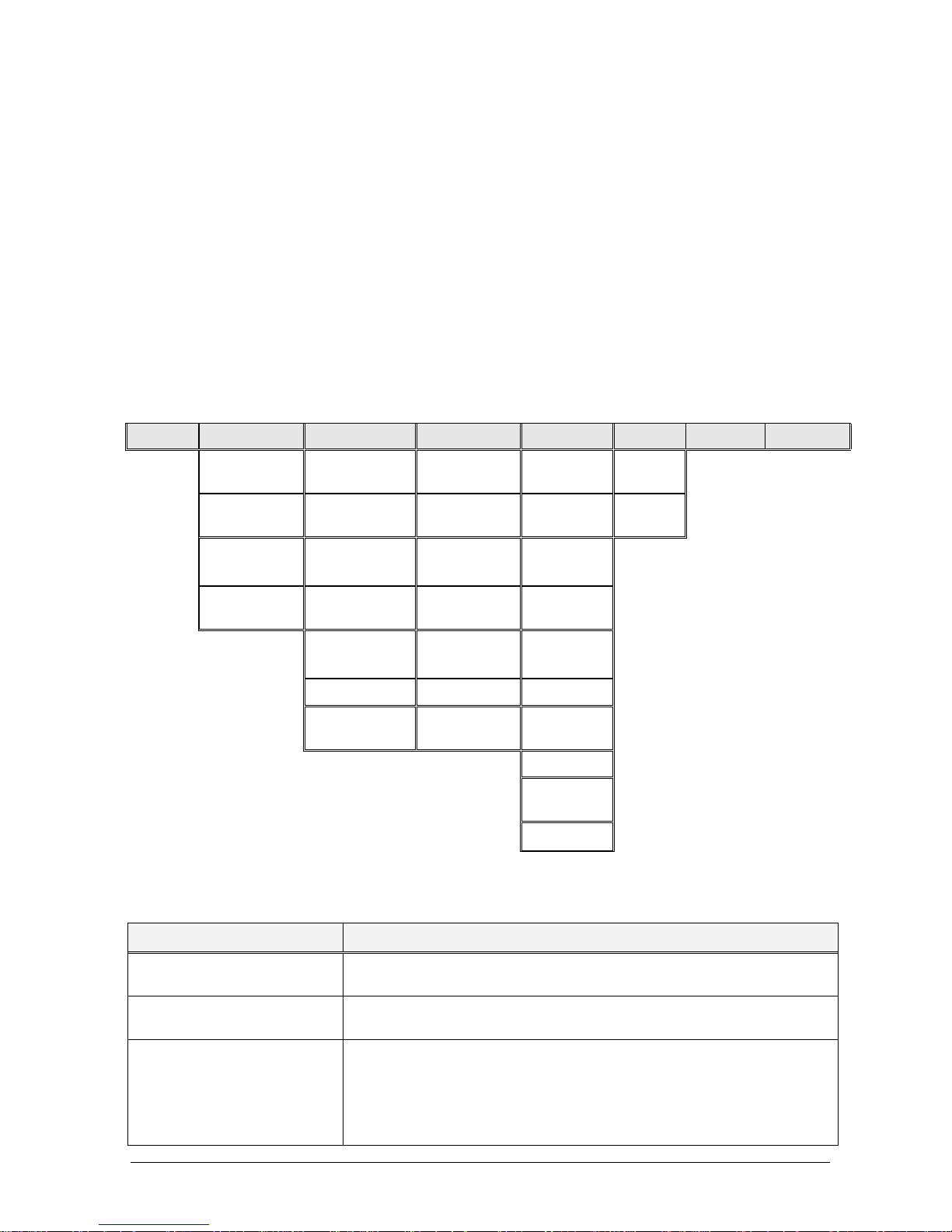
1.1.1 MAIN TASKBAR
The following menus can be accessed from this taskbar. These are used to control the performance of the
analyser, to change and program methods, to run samples and quality controls and to archive sample and quality
control results. More information is given from paragraph 3.3 to 3.10.
Monitor Checks Routine Archive Parameters Help Log off Shut Down
Water Blank
Level
Work List Setup Patients Methods Guide
Reagent
Volumes
Result by
Patient
Calibrations Profiles Info…
Reagent
Config.
Result by Test Backup Ratio
Predilution Calib.&
Q.C.Setup
Restore Calibrators
Calibration
Results
Test Counter Controls
Q. C. Results Events Log Options
Receive from
Host
Admin Log Sampling
order
Print Order
Report
Options
Accounts
1.1.2 DESK TOP
The “Desk Top” contains lists and a visual illustration of the following sections:
Section Definition
“Reagent” List List of the position of the reagents and their respective containers (colours) on
the reagent plate.
“Calibration” List List of the position of the calibrators and controls in the dedicated rack in the
reaction plate. Position 12 is dedicated to water.
Plates
Reagent plate with 24 reagents and 12 calibrators and controls positions;
Sample plate composed of four racks with eight positions for sample cups
and corresponding 8 predilution positions or a predilution rack with 25
positions.
Reaction plate composed by six racks with twenty cuvettes.
Page 31

Chapter 03 – SOFTWARE DESCRIPTION
CYANExpert 130 User Manual Rev.02, May 2014 Chapter 3, Pag e 5
Reagent and Calibration list:
Reaction Plate:
1.1.3 V
IEW DATA/DETAILS AREA
Located in the lower section of the System Monitor mask, the View Data/Details Area contains precise, detailed
information concerning the item selected (cuvette, sample, reagent, calibrator, control) or warning.
It is possible to view data details regarding single items by clicking on them whenever the mouse pointer turns
into a question mark as it passes over that particular element.
If a position on the Reaction plate is selected, a table containing the water blank levels or WBL (See Checks
menu) of the cuvette selected will be shown (both the main channel and the reference channel values).
If a position on the Sample rack is selected, information regarding the sample itself (patient name, sample ID
(SID), rack and position) will appear in the upper portion of the window. In the lower portion of the window, a
table listing the tests programmed to run (pending) on that sample will appear or information concerning the
results if the test is already run.
Placed to the left in the “System Monitor” mask, the reagent list allows the user to
view the list of the position of the reagents associated with the methods programmed
in the “Methods” mask and set up in the “Reagents Plate configuration” in use (eg
Plate 1). It allows the user to put the reagents on the right place on the Reagent Plate.
The colour of the reagent indicates the size of the container to use and is set up under
“Reagent configuration”.
The calibration list indicates the name and the position of the calibrators and/or
control as definined in the “Calibrators” and “Controls” definition mask under
parameters and set up in the “Plate configuration” and “Calib and Q.C. Setup”
menu.
T
his section is the visual illustration of:
Reagent plate with 24 reagents and 12 calibrators and
controls positions;
Sample plate composed of four racks with eight positions
for sample cups and corresponding 8 predilution
positions. The four positions are indicated with A, B, C and
D. A maximum of 2 sample trays can be replaced by
predilution racks with 25 positions each.
Reaction plate composed of six racks with twenty semi-
disposable cuvettes, numbered from 1 to 6.
Page 32

Chapter 03 – SOFTWARE DESCRIPTION
CYANExpert 130 User Manual Rev.02, May 2014 Chapter 3, Pag e 6
If a position on the Reagent rack is selected, information regarding the selected reagent will be shown: in the
upper portion, the name and position; in the lower portion, the methods in which this reagent is used and
information regarding the volume.
If a position on the Calibrator and control rack is selected, information regarding the selected calibrator or
control will be shown.
Furthermore, during the running of the analyses, the heading of this area indicates the operation that the system
is carrying out. The information given includes:
RBL running (in method calibration phase);
Calibrator running (in method calibration phase);
Control running (in calibration and sample analysis phase);
SID – Short name for the Method – Predilution ratio (in sample analysis phase).
1.1.4 LEGEND
There are four different sections in the legend mask:
1. Legend concerning the reagent and sample status (upper right). The reagent and sample containers will be
shown in the corresponding colours on the plate.
2. Legend concerning the type of reagent bottles with different volume capacities (middle right). The names of
the reagents will be shown in the corresponding colours in the reagent list.
Remarks:
Cypress 35 mL bottles are indicated in white, 6 mL bottles in sky-blue. The other bottle colours are currently
not used.
Page 33
Chapter 03 – SOFTWARE DESCRIPTION
CYANExpert 130 User Manual Rev.02, May 2014 Chapter 3, Pag e 7
The operator can select the bottle size to be used by default in the “Options” menu under “Parameters”. The
user can adapt the bottle size for each reagent container separately in the “Reagents Configuration” by
clicking the right mouse button on the reagent name in the list and checking the correct size/colour!
It is extremely important that the indicated bottle sizes in the software correspond to the real bottles
put on the reagent plate.
3. A legend concerning the type of sample cups/tubes with different volume capacities (lower right). The
number of the work list will be shown in the corresponding colour on the plate. Predilution racks always
contain 0.8 mL cups.
Remarks:
In primary racks, primary tubes and 3 mL cups can be placed.
Short cups have a volume of approximately 1 mL.
By clicking on “Options” under the “Parameters” menu, the operator can select the cup to be used by default.
Only one type of cups (at the same time) can be used for all 4 racks (with exception of predilution cups).
It is extremely important that the indicated sample cup size in the software correspond to the real
sample cups put on the reagent plate.
4. A symbol regarding STAT-samples. Samples having this symbol will be processed before all the other
programmed and loaded samples.
1.1.5 COMMAND BUTTONS
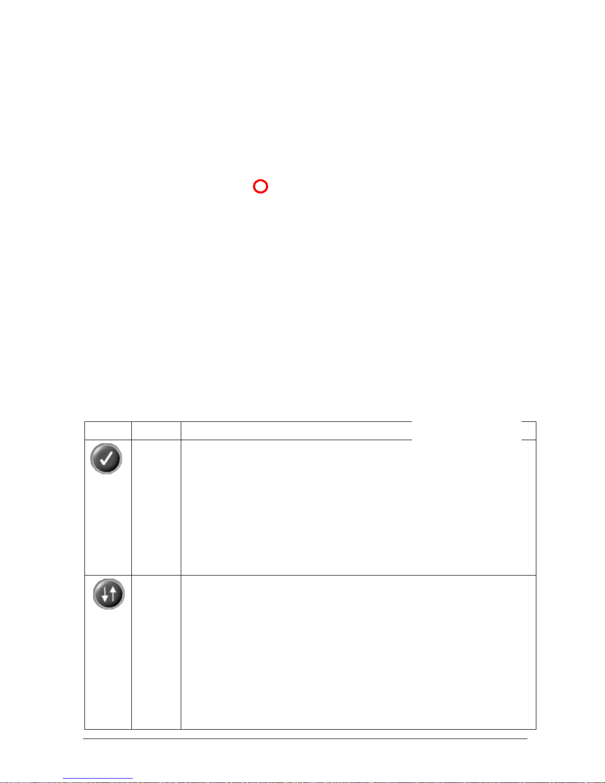
The Command Buttons are automatically activated if needed and have the following functions:
Symbol Name Description
Check
Button
This button is used for the validation of a result of a given test.
This command is activated in Routine – “Result by Patient” and “Result by Test”.
In these menus, the operator has the possibility to view, select and confirm the results of
a test by using the Check button. E.g. in case the same test is repeated for the same
patient, the operator can, by selecting the result(s) that are deemed correct and clicking
this button, make the selected tests “valid”. Validated result(s) are shown in bold on the
screen.
In case of multiple replicates (repetition of the same test for the same patient), only the
validated result(s) will appear on the Patient Print Report. If no result is validated, only
the last measured result will be printed on the Patient Print Report.
Sort
Button
The sort command is activated in:
Routine – “Result by Patient” and “Result by Test”
Archive – “Patients”, “Calibrations” and “Test Counter”
A “Data Sort” mask will automatically open, allowing the user to select from the offered
options and perform the operation.
The operator must first click on the column name, within the “Keys” area, that is to be reordered and then click on “Set”. The selected name will be listed in the “Sort Key List”
area, ready to be re-ordered. By selecting a name and clicking on “Remove”, the name
can be removed again from the ‘Sort Key List’-area.
Page 34
Chapter 03 – SOFTWARE DESCRIPTION
CYANExpert 130 User Manual Rev.02, May 2014 Chapter 3, Pag e 8
For each column name that is to be re-ordered the operator can choose from two
ordering options, Ascending or Descending, located between the “Key” area and the
“Sort Key List” area.
After all the above-described selections have been made, click “OK” to have the
instrument carry out the ordering procedure. The Data Sort mask will close and the list
will now be shown according to the order requested by the user.
To annul the operation and exit the Data Sort mask, click “Exit”.
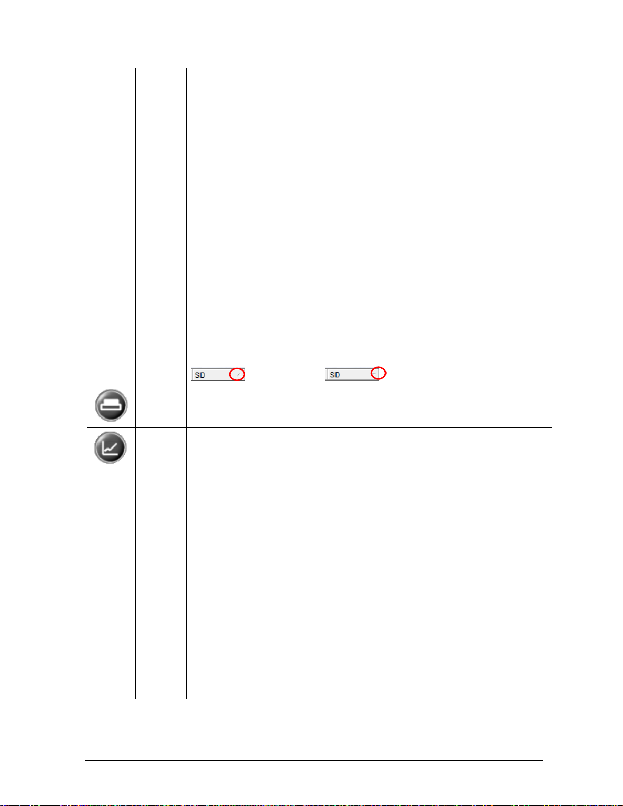
Re-ordering can also be requested directly in menus, by clicking on the small triangle
symbol that appears next to the name in the column heading.
order ascending, or order descending.
Print
Button
To print the selected data. This command can be selected in almost every menu.
Graph
Button
To view the graphical illustration of the absorbances obtained at the programmed
reading times (Methods) for the result selected.
Select the row in the Details Area and then either double click on it with the mouse or
click on the “Graph” button.
This Graph button is activated only when the Details Area contains at least one row of
data.
Page 35
Chapter 03 – SOFTWARE DESCRIPTION
CYANExpert 130 User Manual Rev.02, May 2014 Chapter 3, Pag e 9
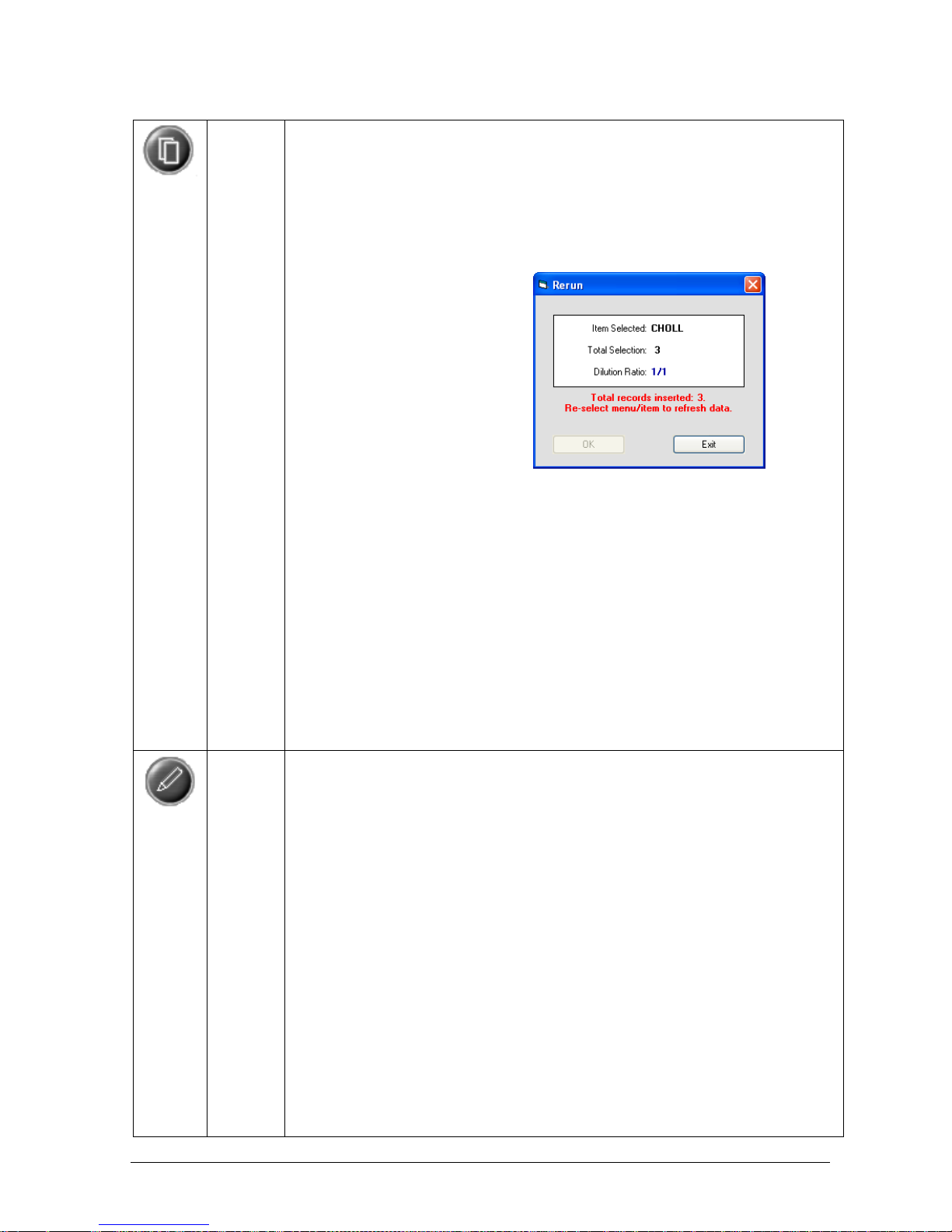
Rerun
Button
To repeat the selected tests with or without dilution. It can be used whenever a rerun is
required for a correct analytical result (e.g.: the sample appears too concentrated, the
quantity of reagent seems insufficient, etc.).
This command is activated in Routine – “Result by Patient”, “Result by Test”, and
“Calibration Results).
First program the samples to rerun. Select the required row and click on “Rerun”. A
“Rerun” window will appear containing the following information:
Item Selected: If only one type of test has been selected, the name of the test to
rerun will be shown. If more than one type of test has been selected, the window will
show “multi-selection”.
Total Selection: Allows the operator to view the total number of reruns requested
for the selected test(s);
Dilution Ratio: Allows the operator to choose, using a pull-down menu, the dilution
ratio for the rerun. This is possible only when one single type of test has been
selected. It is not possible when a multiple selection is requested or when the sample
volume is too small (sample volume < 4 μL).
By clicking “OK”, the operator confirms the programming of the rerun. Clicking “Exit”,
instead, annuls the selection.
In order to carry out the programmed rerun, open the Start Work mask, select the
sample racks and press OK.
Edit
Button
To edit/modify the results of the tests performed.
This command is activated in Routine – “Result by Patient”, “Result by Test”, and
“Calibration Results”.
Select the required row from the Details Area and click on the Edit button. A “Result Edit”
window will open.
Insert the new value for the test result and click “OK”. The new value will appear and be
stored in the result field of the test. Furthermore, an “E” will be shown in the Flags
column and on the print report, indicating an Edited Result.
The Exit button allows the operator to annul the editing operation.
Page 36
Chapter 03 – SOFTWARE DESCRIPTION
CYANExpert 130 User Manual Rev.02, May 2014 Chapter 3, Pag e 10
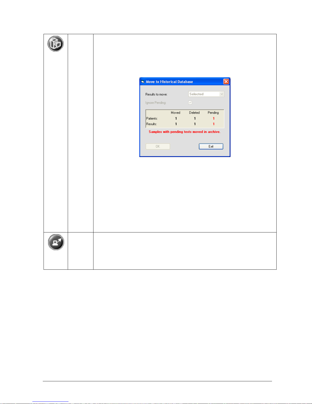
Move to
Archive
Button
All results can be recorded and saved in the Archive memory (to free space in the active
(Routine) memory and keep your PC running smoothly).
This command is activated in Routine – “Result by Patient”. All results from calibrations
are automatically transferred to the Archive - Calibrations.
Select the record to be saved in the Archive from the Main Area and click on “Move to
Archive”. The “Move to Historical Database” window will automatically appear.
This window contains a pull-down menu for “Results to move” where the operator can
choose to save either the records selected from the Main Area, an entire sample rack or
all racks. The central part of the window contains the number of records moved, deleted
or pending for both Patients and Results. To confirm the move, click “OK” and the
selected data will automatically be moved and thereby recorded in Archive – Patients,
where they can be consulted.
The Exit button annuls the move and the operation.
Note: By checking “Ignore Pending”, the results of a patient of the tests already
performed, will be moved to the Archive. If this patient had assigned tests that are not
yet performed (Pending, and thus NO results), these tests will be deleted. Thereby
making the positions in the sample rack free and available again.
Unload
Button
This command makes it possible to activate data transmission to a Host.
This command is activated in Routine – “Result by Patient”, only if Host Connection is
selected in the Option Menu - Parameters.
Select one or more rows from the Main Area and click on “Unload button”. The program
will guide the operator during the data transmission, via a series of visual text messages.
The various icons are activated in accordance with the mask being used. It is possible to recognize an inactive
button by its opaque colouring or by the fact that it cannot be selected. If the user places the mouse pointer over
an icon, a visual text message will appear describing the corresponding function, if the function is active.
Page 37
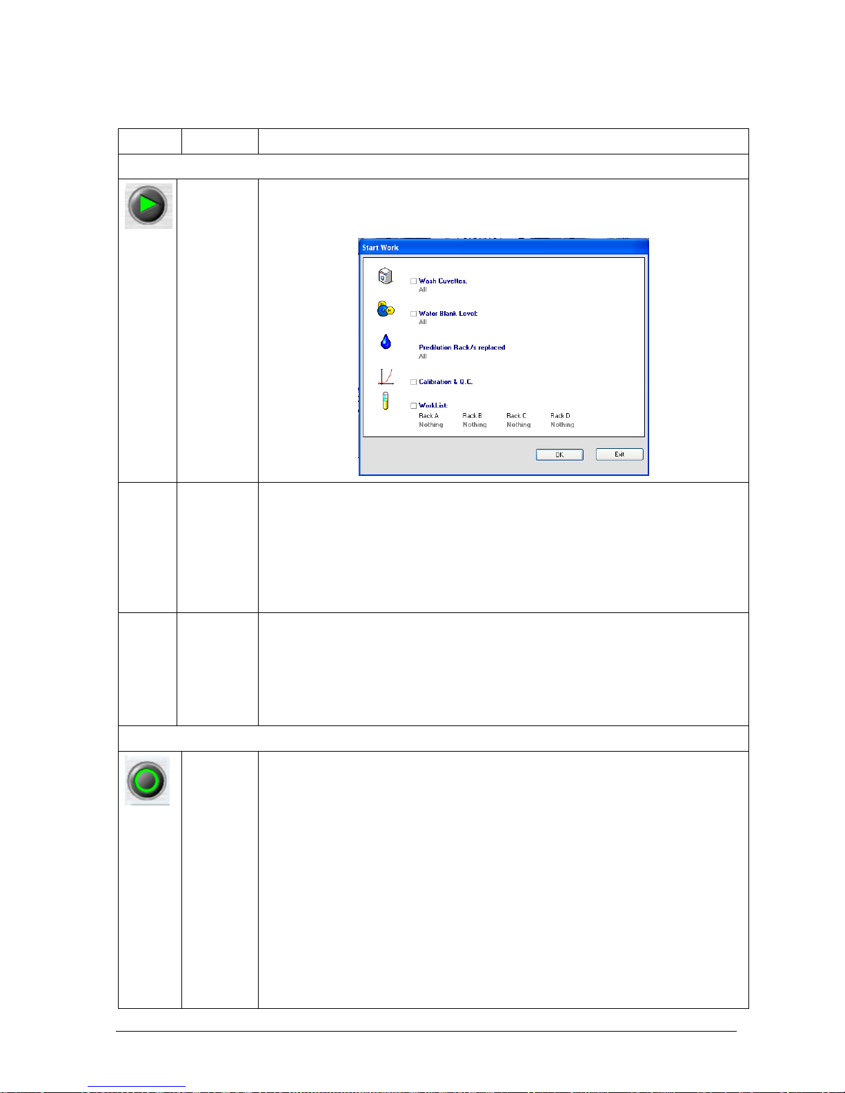
Chapter 03 – SOFTWARE DESCRIPTION
CYANExpert 130 User Manual Rev.02, May 2014 Chapter 3, Pag e 11
1.1.6 OPERATIVE BUTTONS
Symbol Name Description
ACTIONS
Start Button To access the “Start Work” Mask, where it is possible to start running the various tests
and any other operation regarding the analyser (wash cuvettes, WBL, replace
predilution rack(s), run calibration and quality controls, run samples).
Pause
Button
Clicking this button temporarily interrupts the sampling process. It does not interrupt
the incubation nor reading of the samples already dispensed. Therefore, the instrument
first enters a “Pausing” mode until all readings are performed and will only then go into
“Pause” mode. To restart, press the Start button and re-launch the operation.
Note: In case of a warning or small error, the instrument is automatically put in “Pause”status. After resolving the warning, the instrument has to be manually restarted by
pressing the Start button.
Stop Button Clicking this button immediately halts the instruments’ functioning. All the already
dispensed tests are lost.
Note: In case of a fatal error, the instrument is automatically put in the “Stop”-status.
After resolving the warning, the instrument should be manually restarted by pressing
the Start button. The used cuvettes should be washed and the samples that were
already pipetted (and lost) must be reprogrammed.
LOADING
Load
Reaction
Rack
Button
To change a specific reaction cuvette rack. By clicking it, the following dialog box will
automatically open and the racks to be replaced can be selected (from 1 to 6).
By clicking “OK”, the instrument starts a priming cycle. Then the reaction plate turns to
bring the selected rack in front of the operator to facilitate the rack replacement. After
physically replacing the rack, confirmation should be done by clicking again “OK” in the
newly opened window.
Page 38
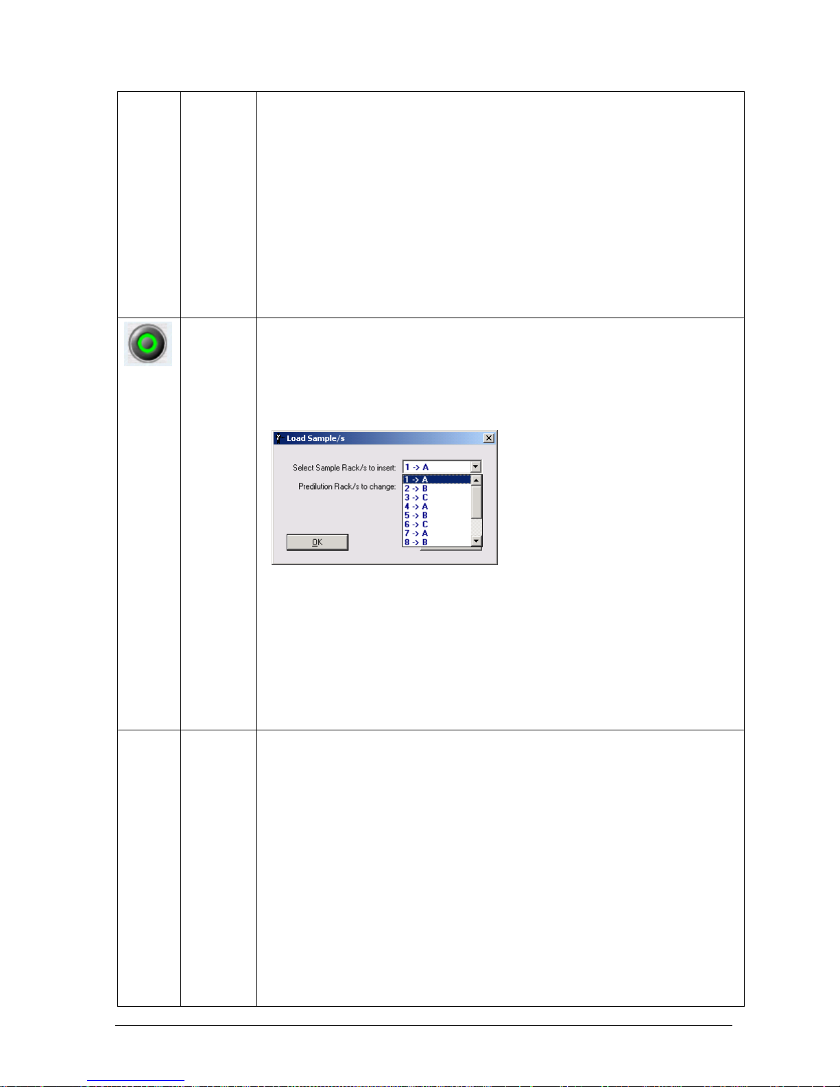
Chapter 03 – SOFTWARE DESCRIPTION
CYANExpert 130 User Manual Rev.02, May 2014 Chapter 3, Pag e 12
Notes:
1. Cuvette racks can only be changed (enabled) when the instrument is not
performing any operation (Stand-by mode).
2. If one or more cuvettes illustrated on the system monitor are coloured red, it is
because the instrument cannot perform the required readings because their
transparency is below or above the acceptable minimum or maximum limit.
3. The cuvettes WBL filter readings can be viewed in the details area, by selecting the
cuvette or in the Water Blank Menu under Checks.
4. When a new cuvette rack is inserted in the reaction plate, it is always indicated in
red on the System Monitor because the instrument does not have the data
necessary for the mathematical calculation of the test results (zero point).
Therefore, it is necessary to carry out a WBL for that cuvette rack in order to be able
to use it (Start Work mask).
Load
Sample/s
Button
To load sample racks. By clicking it, the following dialog box will automatically open and
the sample racks to be inserted can be selected (from A to D).
By clicking “OK”, the sample plate turns to bring the selected rack in front of the
operator, to facilitate the sample rack loading. After physically loading the sample rack,
confirmation has to be done by clicking again “OK” in the newly opened window. Press
the Start button and confirm by clicking “OK” to continue the analyses.
Notes:
1. Sample racks can be loaded at any time (continually), even if the instrument is in
running condition (performing analysis). In this case, clicking the load button, the
instrument will pass from the Running to the Pausing and then to the Pause
condition, to allow the selected rack to be loaded.
2. If one (P1) or two (P2) predilution racks are programmed in the plate configuration,
these can be changed in this mask as well. They are positioned instead of the
primary sample racks. Therefore, if one predilution rack is programmed, only
sample racks A to C can be selected.
Load
Reagents
Button
To load reagents. By clicking it, a dialog box will automatically open, and the selection to
change ALL reagents can be done on the pull-down menu.
Refill the reagents (when level is low) or insert the new reagents (in case of a new STAT
sample/method and addition in plate configuration) and confirm the loading by clicking
“OK”. Press the Start Button and confirm by clicking “OK” to continue the analyses.
Note: Reagents can only be loaded in the running condition. Pushing the load button
brings the analyser from the Running to the Pausing and finally to the Pause condition,
to allow the reagents to be loaded.
Page 39
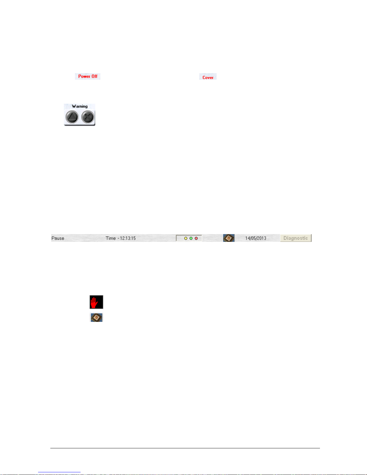
Chapter 03 – SOFTWARE DESCRIPTION
CYANExpert 130 User Manual Rev.02, May 2014 Chapter 3, Pag e 13
1.1.7 WARNING LIGHTS
There are two types of alarms:
1. The first type is a brief visual text message, which appears above the Racks Replacement buttons. It informs the
operator “
” (no connection with instrument), or the “ ” (cover is open), or that a “remote link” is in
operation.
2. The second type are two Warning Buttons (located in the upper right portion of the system monitor mask):
- “Warning error” represented by the triangle, that lights up yellow. By clicking on this button, the event that
is causing the warning (e.g.: liquid(s) finished or temperature over-range) is shown in the Details Area.
- “Fatal Error” represented by the X, that lights up red. By clicking on this button, the event that is causing the
warning is shown in the Details Area.
Whenever a fatal error is given, only those readings that have already been carried out will be saved; the
operations happening at the time of the error are interrupted (e.g.: incubation) and data are lost.
After resolving the “Fatal Error”, the instrument should be manually restarted by pressing the Start button. A
Wash cuvette cycle has to be carried out to empty and clean the used cuvettes and the samples that were
already pipetted (and lost) must be reprogrammed and rerun.
It can be useful for the operator to consult the Events Log (Archive menu) where all instrument status information
is stored, in order to have more information regarding the occurrence of the error.
1.1.8 DIAGNOSTIC & STATUS BAR
The Diagnostic button allows the user to enter and exit the diagnostic menu.
The Status Bar contains information regarding the functional condition of the instrument. The following
information allows the operator to follow and check the status of the instruments operation:
Date & Time
Status: Stand By, Stop, Washing, Running WBL, Running, Pause, Pausing, Safe, Priming
Icon indicating a fault sample reading executed by the Bar Code reader
The firmware version is shown when passing over it with the mouse pointer
Page 40
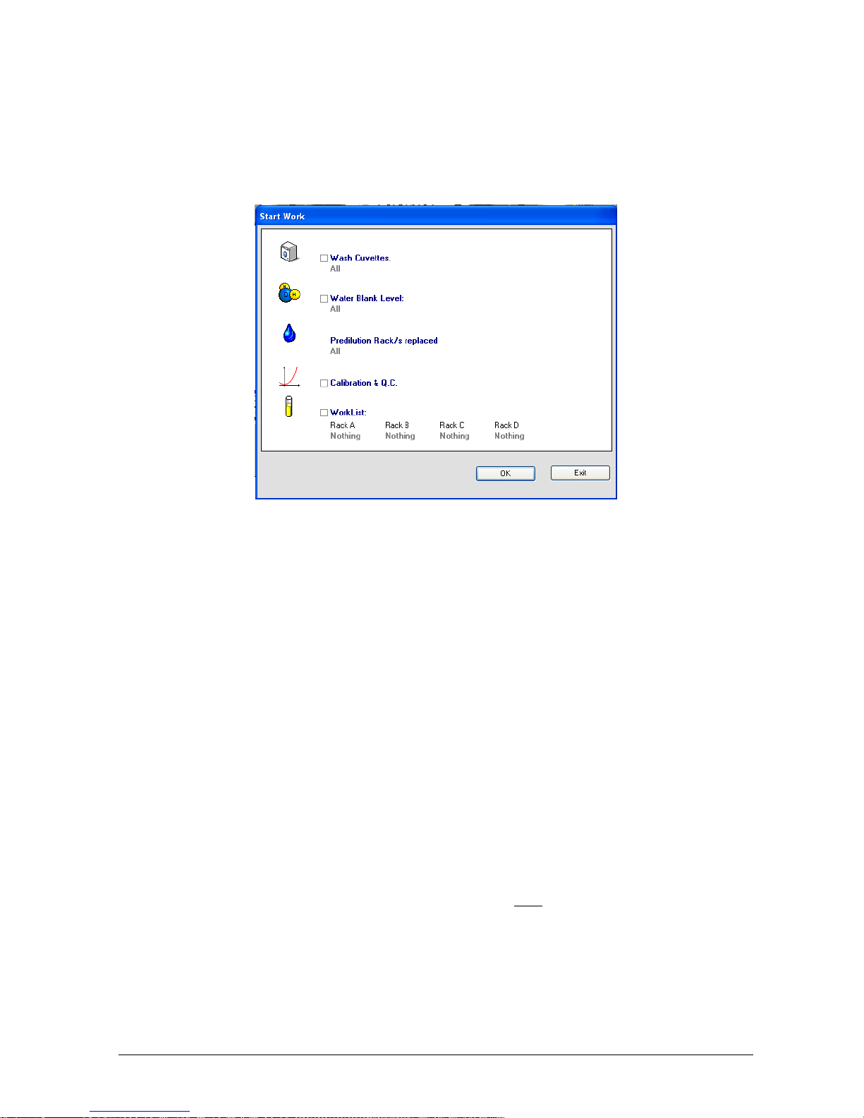
Chapter 03 – SOFTWARE DESCRIPTION
CYANExpert 130 User Manual Rev.02, May 2014 Chapter 3, Pag e 14
1.2 START WORK
The “Start” button (System Monitor) opens the “Start Work” window. Here the user can select, as
needed, from among the following: Wash Cuvettes, Water Blank Level, Replace Predilution Rack(s), Calibration &
Q.C, and Work Lists
1.2.1 WASH CUVETTES
Here, the user can select which reaction cuvette racks in the reaction plate have to be washed by the instrument.
Select, from the field’s pull-down menu, one of the following options: All, Rack 1, Rack 2, Rack 3, Rack 4, Rack 5,
or Rack 6.
The wash cuvettes cycle should be carried out in the following situations:
After replacing the reactions rack
Once a week (after a few days of inactivity, e.g. after the weekend) for a good maintenance
After a fatal error
When starting up the software, this option is highlighted in red and is accompanied by a visual text information
message, “Check if the cuvettes have been washed” at the bottom of the Start Work mask. The program thus
suggests the user that this operation should be carried out before performing any other operations.
Note: Please check if the 4 wash solution bottles are sufficiently filled before performing a wash cycle.
1.2.2 WATER BLANK LEVEL
Here, the operator can select which reaction cuvette racks in the reaction plate have to be checked with a water
blank level (WBL) reading or auto-zero. Select, from the field’s pull-down menu, one of the following options: All,
Rack 1, Rack 2, Rack 3, Rack 4, Rack 5, Rack 6.
The WBL operation (auto-zeroing of the cuvettes) must be carried out daily, before running the Work List tests.
Each cuvette is filled with approximately 400 μL of Rinse solution and read for all the wavelengths of the eight
filters. These readings are essential for determining the cuvette quality and for instrument auto-zeroing, and thus
necessary for accurate result concentration calculations. The user can view the obtained WBL readings in the
“Water Blank Level” menu - Checks, or in the Details Area by selecting the reaction cuvette on the System
Monitor.
Note: Make sure the Rinse solution bottle (I) is sufficiently filled.
Page 41

Chapter 03 – SOFTWARE DESCRIPTION
CYANExpert 130 User Manual Rev.02, May 2014 Chapter 3, Pag e 15
1.2.3 PREDILUTION RACK(S) REPLACED
While the sample racks, the reaction racks and the reagent racks have to be loaded in the “System Monitor” mask
by using the operative buttons, the predilution rack(s) can be replaced in the “Start Work” mask. By a pull-down
menu, the operator can select the following: All – replacement of all the sectors; C – replacement of the
predilution sector C; D– replacement of the predilution sector D. If no predilution rack has been programmed, this
option is not activated.
1.2.4 CALIBRATION & Q.C.
This option enables to run the calibration of methods and to measure quality controls. However, in order to
perform these options, it is necessary to first select and assign the necessary RBLs, calibrators and quality controls
in the Calib. & Q.C. Setup in the Routine menu.
1.2.5 WORK LIST
This option allows the operator to select and run the samples previously programmed in Routine – Work List
Setup and loaded on the sample plate with the Operative button.
There are four positions available for the sample racks, identified by “A”, “B”, “C” and “D”. By selecting the Work
List, the previously programmed and loaded sample racks are activated. After selection, sample racks are shown in
the dedicated area on the System Monitor. Samples are shown in yellow if they are in process and in green if they
have been completed.
Notes:
Samples cannot be activated when their required calibration is not yet performed.
It is also possible to disable a sample rack by selecting “Nothing” in the pull-down menu. This way, the
samples will not be used, even if they are still visible on the System Monitor.
1.2.6 START RUNNING
Click “OK” to start running. Click “Exit” to leave the Start Work menu without carrying out any operation.
Notes:
The “Parameters” menu is blocked (visible, but not possible to adjust) while the instrument is performing any
operations. This is done in order to protect those masks that contain fields where, if the contents were edited,
the results of the operations could be compromised. When the operations have been completed, the
Parameters menu will automatically be reactivated. This reactivation can also be obtained by clicking “Stop”
or “Pause”.
The instrument program will carry out any (programmed) automatic rerunning of the tests without the need
for the operator to intervene. Further rerunning can be requested only after testing has been completed and
before rack replacement.
Page 42
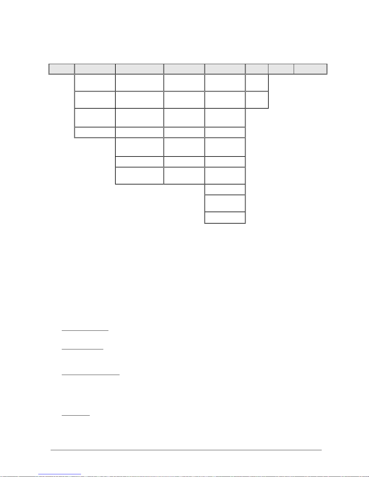
Chapter 03 – SOFTWARE DESCRIPTION
CYANExpert 130 User Manual Rev.02, May 2014 Chapter 3, Pag e 16
1.3 OPERATIONAL MENU (MAIN TASKBAR)
The following menus can be accessed from the taskbar. All these features are explained in the next paragraphs.
Monitor Checks Routine Archive Parameters Help Log off Shut Down
Water Blank
Level
Work List Setup Patients Methods Guide
Reagent
Volumes
Result by Patient Calibrations Profiles Info…
Reagent
Config.
Result by Test Backup Ratio
Predilution Calib.& Q.C. Setup Restore Calibrators
Calibration
Results
Test Counter Controls
Q. C. Results Events Log Options
Receive from
Host
Admin Log Sampling
order
Print Order
Report
Options
Accounts
1.4 CHECKS
“Checks” allows the operator to access and activate functions, as well as view a series of data, both useful and
necessary for correctly preparing the instrument for routine operation.
Water Blank Level: contains a graphic illustration of the results of all the WBLs ran as auto-zeroing and
quality control on each of the 120 cuvettes.
Reagent Volume: contains an overview of all the reagents, controls and calibrators activated on the plate in
the reagent configuration mask. The reagent residual volumes are automatically detected by the level sensor
of the sampling system.
Reagent Configuration: This is a necessary preliminary step. Here, the operator can activate the reagents,
with the indication of their position and its container volume, on the plate. Controls and calibrators for the
activated methods will be indicated once they are programmed (in the “Parameter” mask) and assigned
(“Calibrator & QC setup” in the routine mask). The position of the controls and calibrators can be chosen by
the user, except for position 12 that is dedicated to distilled water.
Predilution: contains all that data regarding the positions dedicated to sample predilution as set-up in the
“Reagent Configuration” mask.
Page 43
Chapter 03 – SOFTWARE DESCRIPTION
CYANExpert 130 User Manual Rev.02, May 2014 Chapter 3, Pag e 17
1.4.1 WATER BLANK LEVEL (WBL)
Mechanism of the reading system:
The reading system (photometer) uses a photodiode to measure the intensity of a light beam after it has passed
through a cuvette. The received analogue values, expressed in mV, read by the photodiodes are then converted
to digital “counts” from 0 to 65553. To compensate for negative counts, the light beam is sent through a black
filter to determine the offset-value. To compensate for possible variation of the signal due to the lamp or the
filters (thermal drift), the light beam is split by a mirror to measure a reference channel (not passing through a
cuvette) for every sample channel (passing through a cuvette) measurement.
Values to be obtained:
Channel (F1-F8) Min. Counts Max. Counts
Sample Channel 28 000 63 000
Reference Channel 34 000 58 000
Channel (F0) Mean Counts Range
Offset 100 ± 50
The values of the WBL are used in the mathematical calculation of test results (autozero) and for performing
quality control checks on the 120 cuvettes (e.g. checking transparency). Consequently, it is very important to
perform this WBL daily for reliable and accurate results.
Select Checks and from the options listed, click on Water Blank Level. The window that opens illustrates
graphically the results of the operations carried out when WBL is selected in “Start Work”. It is divided into two
sections, Main area (A) and Details area (B).
The Main area contains a histogram of the WBL results of the sample channel of the optical filter 340 nm, on a
scale ranging between 28000 and 63000 counts. The Details area gives the values for all the positions of the
photometer filter wheel, both for the reference and the sample channel.
A. Main area
B. Details area
Page 44

Chapter 03 – SOFTWARE DESCRIPTION
CYANExpert 130 User Manual Rev.02, May 2014 Chapter 3, Pag e 18
A. Main Area
By consulting the Main area, the operator has a visual overview and quick indication of the status of the cuvettes.
The histogram indicates the WBL values as explained below:
The initial WBL measurement value is indicated by a grey line;
The penultimate WBL measurement value is indicated in olive/khaki;
The last WBL measurement value obtained is indicated in yellow.
Notes:
1. The difference between the penultimate and the last WBL readings are illustrated by the different colouring
of the histogram bar (a reduction in the counts value), or by the presence of a vertical line on the bar
coloured yellow (an increase in the counts value).
2. The bar is coloured yellow for WBL values falling within the tolerance range (28000 – 63000 counts). If one or
more of the values is out-of-range, a red line will appear next to the number of these cuvettes.
The Main area contains the following fields:
Cuv: indicates the number/position of the cuvette. When the cuvette transparency is insufficient, this
number is shown in red.
D. Rel: difference between the penultimate and the last WBL carried out (1 day since WBL should be
carried out every day). This number should be less than 1000 counts.
D. Abs: difference between the last and the first WBL carried out. This number should be less than 10 000
counts. Moreover, all cuvettes should change to more or less the same degree.
Initial Date: indicates the date the first WBL was carried out (after cuvette replacement).
B. Details Area
Whenever the operator selects a given row from the Main area, the Details area will automatically show more
specific data regarding the values obtained for that specific cuvette.
The obtained values are subdivided into 10 filters (from F0 to F9) and are given for the sample channel (Date)
(light beam through the cuvette) and the reference channel (Ref.) (light beam not through the cuvette). The data
of the last and first measurements are always shown. Intermediate measurements are deleted after a certain time
(as programmed under Parameters – Options – WBL data auto-deletion).
When the cuvette transparency is insufficient, all the data in the Details Area will be shown in red.
By using the Print button, on the left of the interface, the data can be printed.
1.4.2 REAGENTS VOLUME
Select Checks and from the options listed, click on Reagent Volumes. This mask organizes all the data set-up in
the Reagent Configuration and in the Calibration and Q.C Setup mask. Therefore, in addition to the reagents,
their bottle types and residual volumes, the operator can also view data regarding assigned calibrators and
controls. By using the Print button, on the left of the interface, the data can be printed.
This window is divided into two sections, Main area (A) and Details area (B).
F0
Dark filter offset value
F1 340 nm
F2 380 nm
F3 405 nm
F4 492 nm
F5 510 nm
F6 546 nm
F7 576 nm
F8 620 nm
F9
T
otal Light
Page 45

Chapter 03 – SOFTWARE DESCRIPTION
CYANExpert 130 User Manual Rev.02, May 2014 Chapter 3, Pag e 19
A. Main Area
The Main area field contains the following items:
Position: The position of the reagents in the reagents rack (24 positions available); and of the
calibrators/controls in their designated rack (12 positions available, with position 12 reserved for distilled
water).
Type: indicates the type of liquid programmed.
Name: indicates the reference acronym for that liquid.
Cup/Bottle Type: indicates the volume (35 mL or 6 mL) of the container programmed for that reagent
(Reagent Configuration). Calibrators and controls should be placed in short, 1 mL cups.
Residual Volume (mL): quantity of reagent left in the container and available for use in other analyses
(this information is automatically updated as each test is carried out). The amount is a decimal figure,
expressed in mL.
B. Details Area
If a reagent or diluent is selected in the Main area, this area contains the following details:
Type: indicates the type of liquid programmed.
Name: indicates the full name of the liquid programmed.
Predil. Ratio/Volume (μL): if the indicated liquid is a diluent, this field expresses the predilution ratio set-
up. Otherwise, it indicates the volume of reagent necessary for each reaction.
Rinse (μL): quantity of rinse liquid used to avoid an intermixing (i.e. cross-contamination) of the reagents,
as programmed in Methods – Parameters.
Residual Volume (mL): quantity of reagent left in the container and available for use in other analyses
(this information is automatically updated as each test is carried out). The amount is a decimal figure,
expressed in mL.
If a control is selected in the Main area, the Details area will show the type, name, lot number, and expiration date.
If a calibrator is selected in the Main area, the Details area will show the type, name, lot number, expiration date,
the number of points, and the corresponding diluent.
A. Main Area
B. Details Area
Page 46

Chapter 03 – SOFTWARE DESCRIPTION
CYANExpert 130 User Manual Rev.02, May 2014 Chapter 3, Pag e 20
Notes:
1. When the level of a reagent drops below its “reserve level”, the position of that reagent will be coloured
magenta (low level) in the System Monitor;
The “reserve levels” are as follows:
5.7 ml for the 35 ml container
1.8 ml for the 6 ml container
2. When the reagent container is empty, the position of that reagent will be coloured red (error) in the System
Monitor. There will be an audio warning message;
The “dead volumes” are as follow:
1.4 ml for the 35 ml container
0.8 ml for the 6 ml container
1.4.3 REAGENTS CONFIGURATION
Select Checks and from the options listed, click on Reagents Configuration.
This window contains the following areas:
The right area illustrates the reagent tray (including calibrators and controls), the samples and predilution
racks.
The left area is dedicated to:
o Programmed methods: Checked in the (all) method list and listed with their corresponding
position on the plate and container volume indicated in sky blue (6 mL) or white (35 mL).
o Programmed controls with their corresponding position.
o Number of predilution racks.
Page 47
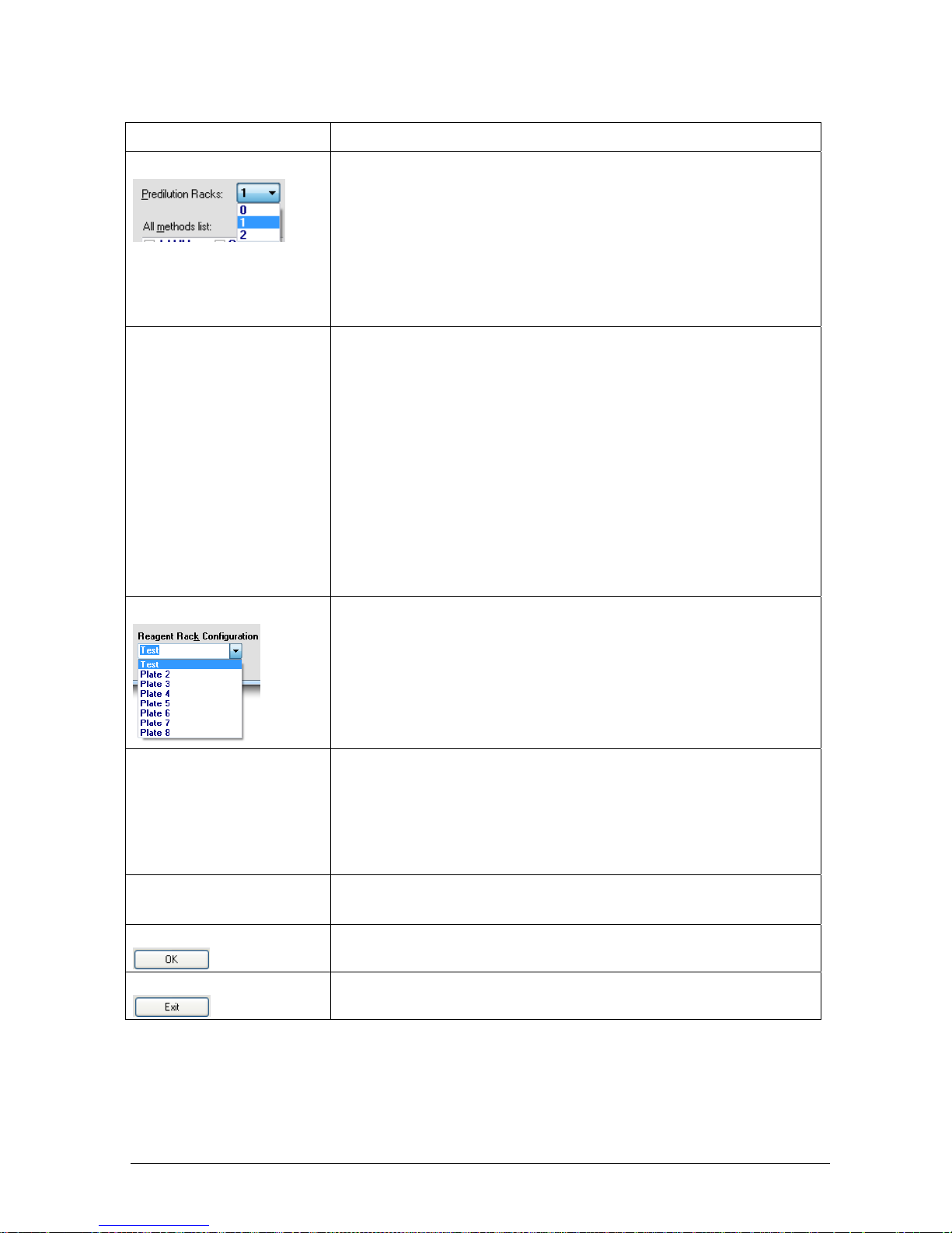
Chapter 03 – SOFTWARE DESCRIPTION
CYANExpert 130 User Manual Rev.02, May 2014 Chapter 3, Pag e 21
The following actions can be performed to configure the analyser to the customer’s need:
Item Description
Predilution Rack:
A number from 0 to 2 predilution racks can be selected in the pull-down
menu. These racks are dedicated to the predilution of samples, calibrators or
controls (for methods that require a predilution as a default action) and are as
follows:
0 No predilution rack.
1 Sample rack position D will be dedicated to the predilution rack P1.
2 Sample rack positions D and C will be dedicated to the predilution racks
P2 and P1 respectively.
All methods list:
The methods are listed in alphabetical order. By selection of a given test, the
software automatically positions the required reagents and diluents (bound
to that specific test) on the first free position on the reagent tray. The operator
can change the position by using the mouse via the Drag & Drop function.
The name of the reagent positioned in the rack will be shown in the colour
that indicates its container volume. In order to change the format of the
reagent container, the operator must right-click with the mouse on the name
of that reagent. This will open a dialog box where the operator can select the
desired type of container (35 mL or 6 mL).
It is very important that the programmed container is the same as the
real container, in order not to break the sampling probe.
Note: Methods that require a predilution are not listed when there is no
predilution rack selected.
Reagent Rack Configuration
The user can program up to 8 different reagent configurations. The desired
programmed reagent plate can be selected from a pull-down menu.
Moreover, it is possible to rename a given plate configuration. The user can
always view the reagent configuration the instrument is using under System
Monitor.
Controls
Controls can be activated or deactivated by clicking on the corresponding
“box”. The instrument will automatically assign an activated control to the
first free position in the Calibrator/Control rack. The operator can change this
position by using the mouse via the Drag & Drop function.
Barcode button
This button is only available when the reagent barcode reader is selected in
the options menu (see 3.7.6).
Save button
The “OK” button allows to save the change(s) made and confirm the
configuration of the selected reagent(s) and controls.
Exit button
The “Exit” button allows to close the Reagents Configuration mask and to
return to the System Monitor without saving any modifications.
Page 48
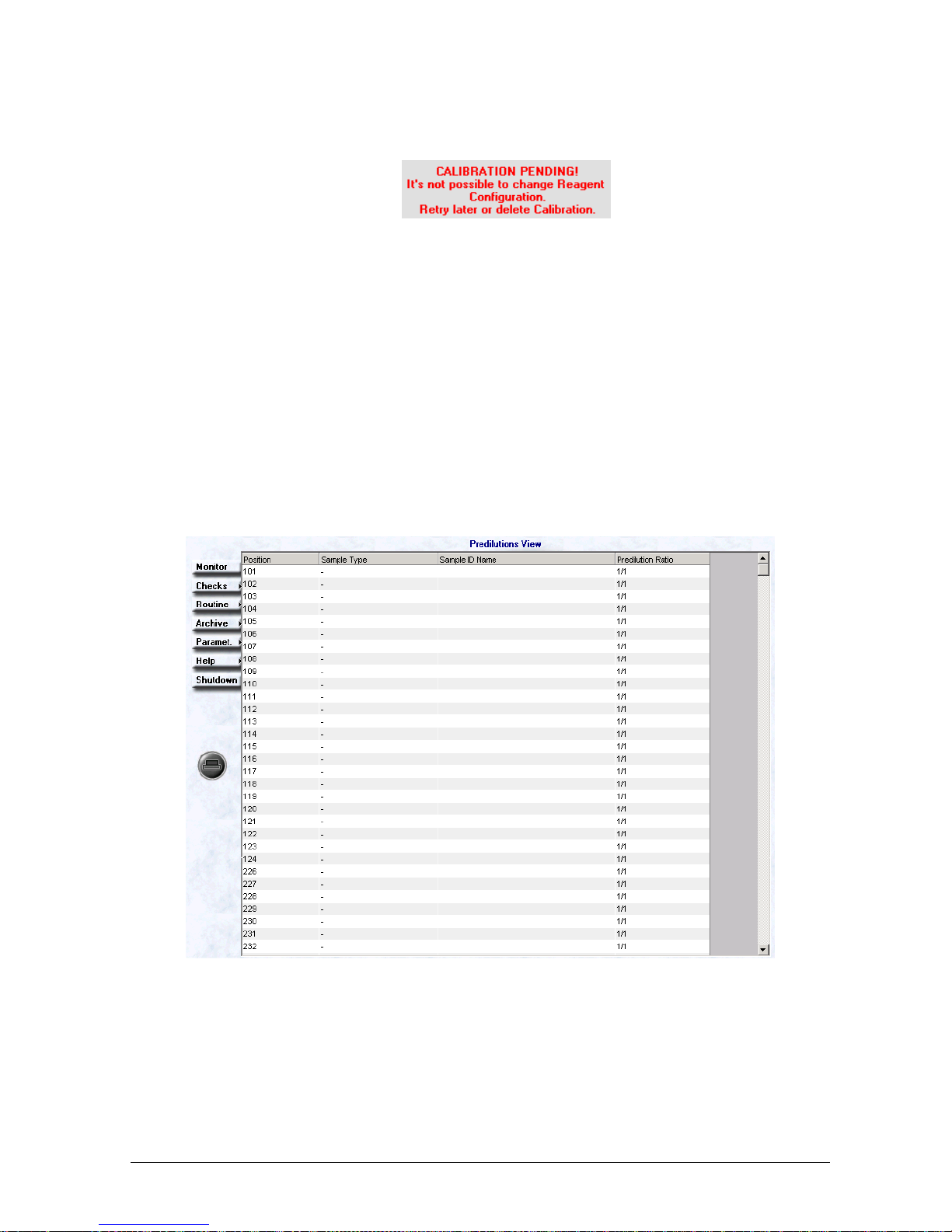
Chapter 03 – SOFTWARE DESCRIPTION
CYANExpert 130 User Manual Rev.02, May 2014 Chapter 3, Pag e 22
WARNINGS:
1. If the operator enters the Reagents Configuration window once the calibration has been assigned, the
following message will appear:
In order to make any changes, the calibration has to be either carried out or eliminated from the
programming (delete pending in Calibration & Q.C. setup).
2. If the name of the reagent is changed in the Methods, it will also be eliminated from the Reagents
Configurations. The System Monitor will therefore no longer show the name of the configuration in use,
but will instead indicate “INVALID”. The operator gets the following message:
CONFIGURATION NOT VALID!
Methods definition has been changed.
Select a new Reagent Tray Configuration and
Check its methods.
In this case, it is the operator’s responsibility to insert the modified test in the Reagents Configurations
and confirm the change by clicking “OK”.
1.4.4 PREDILUTION
Select Checks and from the options listed, click on Predilution.
This window contains all data regarding the pre-diluted samples activated under Reagents Configuration.
Position: position assigned to the diluted sample in the sample rack and in the predilution rack. The
numbering goes by 101 to 132 for the sample rack and by 201 to 250 for the predilution rack positions.
Sample Type: to view the type of diluted sample (Serum / Urine).
Sample ID name: indicates the ID code of the sample and the patient name.
Predilution Ratio: indicates the predilution ratio of the sample as set-up in the corresponding method.
By using the Print button, on the left of the interface, the data can be printed.
Page 49

Chapter 03 – SOFTWARE DESCRIPTION
CYANExpert 130 User Manual Rev.02, May 2014 Chapter 3, Pag e 23
1.5 ROUTINE
“Routine” contains the menus for programming the patients and the calibration of the related tests. It also
includes the menus for checking the results of the performed operations.
Work List Setup: for programming the patient’s personal data, their respective tests and their position on
the sample racks.
Result by Patient: to view the results of the programmed tests per patient, together with their personal
data as set-up in the Work List mask. The user can request a print-out of the patient report(s) and of the
work list(s) setup.
Result by Test: to view all results of the tests carried out.
Calibration and Q. C. Setup: This is a necessary and preliminary step for any calibration. In this mask the
operator requests the RBL, the calibration and the quality controls for each individual method in the
configuration.
Calibration Results: to view the results regarding the “Calibration” and all its related data.
Quality Control Results: to view all the data regarding the quality controls carried out.
Receive from Host: this command makes it possible to receive data from the Host regarding the patients
and the tests to be carried out (only if Host Connection selection is selected in the Option Menu).
1.5.1 WORK LIST SETUP
Select Routine and from the options listed, click on Work List Setup.
This window allows inserting data regarding the patients and their requested tests. This programming phase is
necessary before loading the sample racks and starting the run in the “Start Work” window.
The Work List mask is organized in the following manner:
A. Left-hand side of the screen, dedicated to the selection of the racks and to the positioning of the sample
cups in these racks.
B. Central part of the screen, dedicated to the personal data regarding the patient.
C. Right-hand side of the screen, dedicated to the methods, profiles and ratios requested for a specific
patient.
D. Lower portion of the screen that contains those buttons necessary for the various management
operations regarding the mask.
Page 50
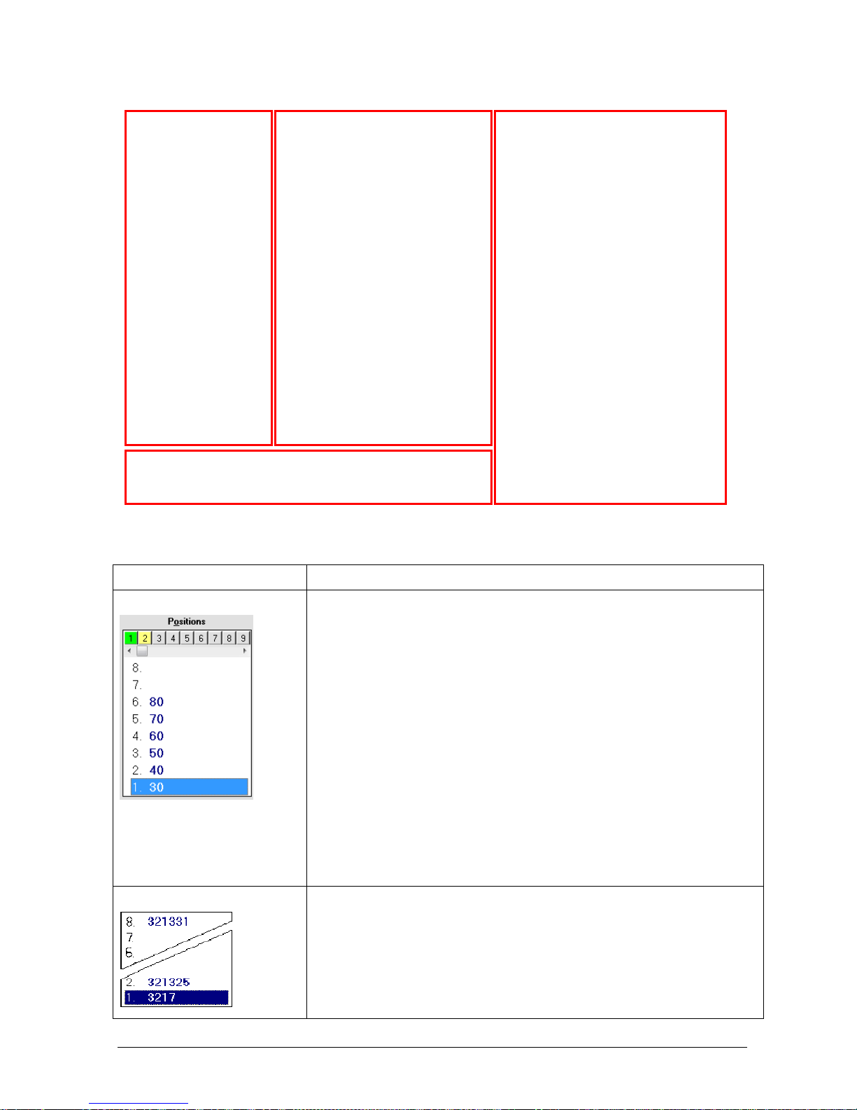
Chapter 03 – SOFTWARE DESCRIPTION
CYANExpert 130 User Manual Rev.02, May 2014 Chapter 3, Pag e 24
A. Positioning of the samples in the racks
In this mask the following actions can be made:
Item Description
Rack position
The position bar has a capacity of 99 racks that can be programmed; each has 8
positions to program samples. The operator can choose, by using the scroll bar
and selecting the rack number, in which rack he wants to program the patient
samples.
Pay attention: when the samples are loaded, rack 1 corresponds to sample rack
A; rack 2 to rack B; rack 3 to rack C and rack 4 to rack D. Rack 5 will again be
loaded on sample rack A. This principle is the same for all 99 available rack
positions.
The colour of the rack gives the following information:
Grey: the rack is available, no samples have been programmed.
Yellow: the rack contains at least one programmed sample.
Green: this is the rack that is selected by the user.
Red: the samples in this rack are being analysed. It is not possible to
cancel the programmed samples of this rack. However, new samples
can be added to run if there are still free positions left.
Cup position
Once a rack is selected, the operator can view the 8 cup positions of the rack,
represented by the first column of numbers. Each cup has its own SID (Sample
IDentification number) as set-up in the Samples card (central area) and this SID
can be viewed in the second column of numbers.
When selecting a cup/SID, the sample’s corresponding personal data is shown in
the central area of the Samples card; and the requested methods, in the right
area of the Methods card.
A. Positioning
B. Patient personal data
C. Methods, Profiles and Ratios
D. Management
Page 51
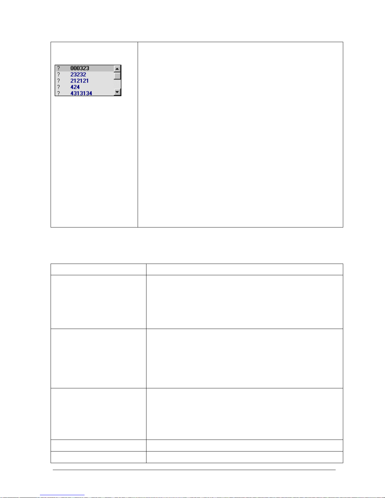
Chapter 03 – SOFTWARE DESCRIPTION
CYANExpert 130 User Manual Rev.02, May 2014 Chapter 3, Pag e 25
Unassigned samples
This mask is only being used in case of a Host Link or a Barcode reader:
1. Host link:
The SIDs of samples programmed and sent to the Work List via the Host
connection, but not yet physically assigned to a specific rack (for example by
barcode reading), will appear in the “Unassigned Samples” field. The SID can be
moved from here in a selected rack and vice versa, via the mouse using the Drag
& Drop function. Please see note 3.7.6 for more information.
2. Barcode reader:
Normally the position assignment will be carried out by the instrument via a
reading of the sample Barcode. This mask allows the operator to also manually
program some samples, which do not have a barcode. Please see note 3.7.6 for
more information.
Pay attention: If, by mistake, an already assigned SID is set-up, the following
dialog box/visual text information message will appear:
Confirm by clicking “OK”, change the SID and then click “Save” once more.
B. Patient Personal Data
Personal data regarding the patient and data regarding the corresponding sample are included in this card:
Item Description
Type
Select from the pull-down menu the correct sample type - Serum, Urine,
Control.
Once the sample has been saved, the sample type can no longer be changed.
At this point it will appear coloured dark grey.
Note: Controls can also be programmed in the sample racks. Please check the
note at the end of this table.
Sample ID The Sample Identification Code is a required field that can consist of a
maximum of 15 letters or digits and can be assigned to only one sample
(unique). A SID will be automatically set-up/proposed by the software,
numerically and progressive. The operator can change the SID, but should
pay special attention as a duplicate SID is not allowed.
Once the sample has been saved, the SID can no longer be changed. At this
point it will appear coloured dark grey.
Patient ID Patient Identification Code is a required field that can consist of a maximum
of 15 letters or digits. It is an unequivocal reference code, unique to that
individual patient. Different SIDs can be assigned to the same PID, since a
patient can be tested more than once.
Once the sample has been saved, the PID can no longer be changed. At this
point it will appear coloured dark grey.
Last Name The patient’s last name (family name/surname)
First Name The patient’s first name (given name)
Page 52

Chapter 03 – SOFTWARE DESCRIPTION
CYANExpert 130 User Manual Rev.02, May 2014 Chapter 3, Pag e 26
Sex
Sex of the patient is a required field. Select from the pull-down menu – male
or female. Male is the default setting.
During and after sample running, it is not possible to modify this choice and
the field will therefore appear coloured dark grey.
Birthdate Patient’s date of birth. The data can be inserted by keyboard or by using the
program’s calendar, accessible by first selecting Birthdate, then pressing F4
or by double clicking with the mouse.
In case no date of birth is entered, the patient will be considered as an Adult,
regarding the reference range.
During and after sample running, it is not possible to modify this choice and
the field will therefore appear coloured dark grey.
Admis. Date Date of admission of the patient. By default this is the date of inserting the
sample in the worklist. This date can be modified by keyboard or using the
program calendar, accessible by first selecting Admis. Date, then F4 or by
double clicking with the mouse.
Diluted Ratio The dilution ratio of an already pre-diluted sample. Leaving he predefined
value of “1” unaltered, means that the sample is undiluted. Choosing “2”
means that the sample is diluted manually by the operator in a 1 to 2 ratio.
The calculation of the final result of the test will automatically take into
account this dilution ratio.
During and after sample running, it is not possible to modify this choice and
the field will therefore appear coloured dark grey.
Diagnosis Description of a possible pathology
Location Department, laboratory, hospital or ward
Address Patient’s street address
City City where the patient resides
State State (or country) where the patient resides
ZIP Postal Zip Code
Notes Any information deemed important or useful (25 digits)
STAT Indicates that the sample is urgent and will be executed first, before all other
programmed and loaded samples. After STAT sampling the analyser will
continue with other samples without any further operation by the user.
Stat samples can be loaded on any of the sample rack either on a free or
occupied position. In the latter case, the previously loaded sample must be
removed and re-programmed.
Notes:
1. Samples
For serum samples, it is important that they are well coagulated and then carefully centrifuged, residual
fibrinogen clots can obstruct the probe and lead to inexact sampling.
If blood samples containing gel are used, it is suggested that the manufacturer’s recommendations be
followed.
Page 53

Chapter 03 – SOFTWARE DESCRIPTION
CYANExpert 130 User Manual Rev.02, May 2014 Chapter 3, Pag e 27
2. Programming multiple aspirations from the same sample cups
a) Select the requested sample cup position and check the requested methods.
b) Click “Save”..
c) Reselect the saved sample in the positions area
d) Deselect the methods and then reselect then again.
e) Click “Save for…” and enter the number of multiplicates you want to aspirate and measure.
f) Select a different rack in the positions area.
g) Reselect the rack with the programmed sample cup.
3. Controls in the sample racks
When programming a control as sample type, the mask that appears will be structurally identical but certain fields
will be deactivated:
The main differences with a sample programming are:
1. Name: consists of a pull-down menu, listing the various programmed controls.
2. Methods: only those methods that were assigned to the selected control in the programming of the
control AND are currently configured in the Reagents Plate are shown in the Methods area. The operator
has to check (√) all the tests for which he wants to perform the control. It is not possible to select a Profile
or Ratio in the programming of a control.
C. Methods, Profiles & Ratios
Area Description
Methods The tests are listed in alphabetical order in the Methods area but priority is given to
those programmed in the reagents configuration currently in use by the
instrument. Their status is given by coloration:
Blue: reagent is programmed.
Grey: reagent not programmed.
Click the “check boxes” (√) to program the requested methods for that patient.
The tests highlighted in blue will be run when the sample rack is loaded and the
Page 54
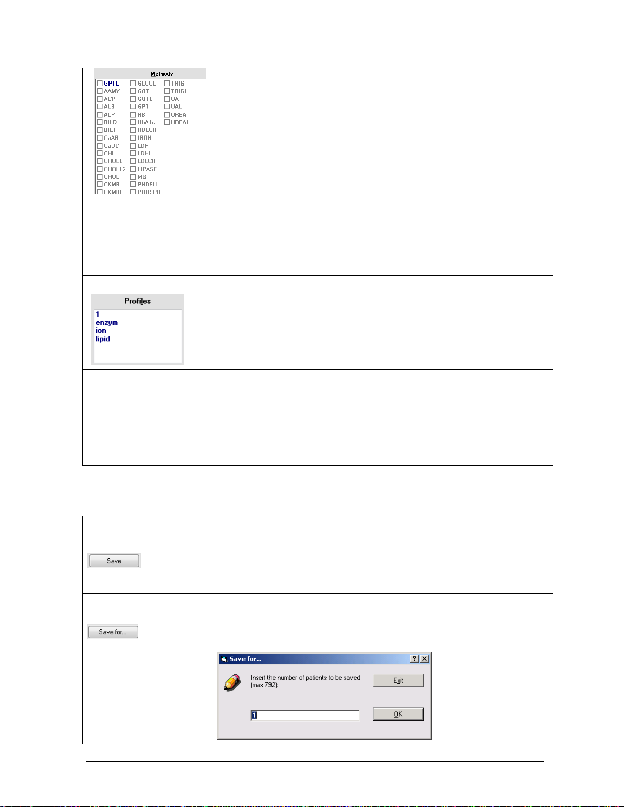
Chapter 03 – SOFTWARE DESCRIPTION
CYANExpert 130 User Manual Rev.02, May 2014 Chapter 3, Pag e 28
respective Worklist is activated in the “Start Work” mask, while those in grey will
remain set-up, but will not be run until the reagents have been configured on the
plate.
The tests will appear coloured dark grey when the instrument is in the process of
performing them or whenever they have already been run for that sample. It is not
possible to modify or change the test selection of tests already performed or those
being run.
Pay attention: If the operator tries to save data without selecting at least one
method, the following dialog box/visual text information message will appear.
Click “OK”, select one or more methods, and click “Save” again.
Profiles Area
When a profile is selected in the Profiles Area, all the tests that are programmed in
that profile (set-up under Parameters) will be automatically selected and a check
mark () will appear in the Methods list.
Ratios Area
When a ratio is selected in the Ratios area, all the tests that are programmed in that
ratio (set-up under Parameters) will be automatically selected and a check mark
() will appear in the Methods list.
D. Managing of the Work List
Action Description
Save for one patient
To save the programming of a patient.
Once the operator has clicked on “Save”, the Positions, Sample and Methods cards
will automatically be updated and another Sample ID, will be proposed for the
next sample.
Save for more than one
patient
To save a programming of data that are the same for more than one patient, use
the “Save for…” button (e.g. more than one patient has the same methods
programmed).
The following dialog box will appear:
Page 55
Chapter 03 – SOFTWARE DESCRIPTION
CYANExpert 130 User Manual Rev.02, May 2014 Chapter 3, Pag e 29
Insert the number of patients for whom the data has to be programmed, within
the maximum available number position in the 99 sample racks. If the number
inserted is greater than the number of positions left free in the originally selected
rack, the program will assign the patients to the next rack. Click “OK” to confirm
and complete the operation. Click “Exit” to cancel the operation.
Notes:
1. All the patients will have a different SID and PID.
2. After saving it is possible to add personal information for a specific patient.
Select the SID on the position list, add the personal information and save
again.
Once the operator has clicked on “Save for….”, the Positions, Sample and Methods
cards will automatically be updated and another Sample ID will be proposed for
the next sample.
Delete a patient
Select the rack and the SID to be deleted in the “Positions” card. Click “Delete
Sample”. This option is not activated if the operator selects a sample contained in
the rack that the instrument is running at that time.
The following visual text information message/dialog box will appear. Click “Yes”
to confirm the deletion; click “No” to annul the request and exit.
! Pay attention! Do not delete a sample that has already been analysed before
having made a print report of the data or moved the data to the archive. If you
do so, the test results will be deleted and will be lost. By transferring the data
to the archives, the sample position will automatically become free again.
Delete a rack
To delete ALL the samples in a rack, select the rack from the “Positions” bar, then
click “Delete Rack”. This option is not activated if the operator selects a rack that
the instrument is running at that time.
The following visual text information message/dialog box will appear. Click “Yes”
to confirm the deletion; click “No” to annul the request and exit.
! Pay attention! Do not delete a rack that has already been analysed before
having made a print report of the data or moved the data to the archive. If you
do so, the test results will be deleted and will be lost. By transferring the data
to the archives, the rack position will automatically become free again.
To exit the work list mask and return to the System monitor.
Page 56

Chapter 03 – SOFTWARE DESCRIPTION
CYANExpert 130 User Manual Rev.02, May 2014 Chapter 3, Pag e 30
1.5.2 RESULT BY PATIENT
Select Routine and from the options listed, click on Result by Patient.
This mask allows to print out the Work List for sample racks preparation. It also contains all that data regarding the
tests performed or to be performed and allows report(s) print-out of the results per patient or transferring of the
results to the archive or host.
This window is divided into two sections, a Main area (A) and a Details area (B). The mask also contains
command buttons. For more information on the command buttons, see paragraph 3.1.5.
A. Main Area
The Main area contains all the information needed to correctly identify the sample.
Item Description
! Indicates a STAT sample
Rack-Cup The rack number and position/cup in the rack used for that sample
Type Type of sample used
Samp. Dil. Dilution ratio used for the sample
SID Sample identification number
PID Patient identification number
Name, Sex, Birthdate As programmed in the work list
A. Main Area
B. Details Area
Page 57

Chapter 03 – SOFTWARE DESCRIPTION
CYANExpert 130 User Manual Rev.02, May 2014 Chapter 3, Pag e 31
B. Details Area
The Details area contains more information regarding the patient selected in the Main area.
Item Description
Test Indicates the tests performed
PreDil. The predilution ratio of the sample
Test Dil. The dilution ratio of the method
Result The result or the status of the test (e.g. pending)
Unit Unit of measurement of the result as specified in the method programming
Normal values The reference values as specified in the method programming
Flags Lists all errors encountered during operation. When an error occurs, all the fields of that
test are automatically shown in red. Furthermore, a small red square () appears in the
Flags field. When passing over this symbol with the mouse, a text message appears with
a description of the error encountered. The errors are signalled using letters that stand
for the type of error encountered – as reported in Report Options - Flags Description.
Date The date and time the test was carried out or edited. If the test is not yet performed
(pending), this field shows the date and time the sample was programmed.
User Indicates the user logged in when test are performed
The following commands are active:
Check button to validate the data
Sort button to reorder the data
Print button to print a report or a work list
Select the row or rows in the Main area to be printed and then click “Print”. A dialog box will appear, asking
to print reports or a work list. Work list print-outs can be useful to the operator in order to prepare the
sample racks. Click “YES”, to print the report of the selected row(s); click “NO”, to print the entire list of the
selected patients. Click on “Cancel” to annul the print request.
Rerun button to rerun the test
Edit button to edit the data
Archive button to archive the data
Deleting a sample rack or a sample in the work list menu without first archiving the data implies loss of the
data! Archived data cannot be edited or re-run anymore.
Unload button to send the data to the Host computer
Page 58

Chapter 03 – SOFTWARE DESCRIPTION
CYANExpert 130 User Manual Rev.02, May 2014 Chapter 3, Pag e 32
1.5.3 RESULT BY TEST
Select Routine and from the options listed, click on Result by test.
This mask contains all the data regarding the patients as inserted in the Work List Programming mask and more
specific data concerning the tests carried out. This information is provided in a single “Main Area”.
Item Description
! Indicates a STAT sample
Rack Cup The rack number and cup position in the rack used for that sample
Type The type of sample used
Sam Dil. The dilution ratio used for the sample
SID Sample identification number
Name The name of the patient
Test The name of the method
Results The obtained results or status of the test (e.g. pending)
Unit Unit of measurement used
Test Dil. The dilution of the sample for that specific test in case of rerunning
Flags Lists all errors encountered during operation. When an error occurs, all the fields of that test are
automatically shown in red. Furthermore, a small red square () appears in the Flags field. When
passing over this symbol with the mouse, a text message appears with a description of the error
encountered. The errors are signalled using letters that stand for the type of error encountered
– as reported in Report Options - Flags Description. This field allows the operator to view if any
errors occurred during operation.
Page 59

Chapter 03 – SOFTWARE DESCRIPTION
CYANExpert 130 User Manual Rev.02, May 2014 Chapter 3, Pag e 33
The following commands are active:
Check button to validate the data
Sort button to reorder the data
Print button to print the selected data
Graph button to view the absorbance graph of the selected test
Rerun button to rerun the test
Edit button to edit the data
Note: Precision Check
This mask allows checking how exact the results of a given test(s) are along with their level of precision. To
carry out this check, select the row(s) to be checked and right-click with the mouse.
The “Precision Check” window contains the following useful information:
Test Name: The name of the test to be checked
Total Tests: How many tests of the indicated method are included in the rows selected
Mean: The mean value of the results selected
SD and CV%: The Standard Deviation and Coefficient of Variation of the selected tests
1.5.4 CALIBRATION & QUALITY CONTROL SETUPS
In order to guarantee that the instrument provides reliable test results, correct and precise calibration must be
performed.
This operation should be performed for all tests for which it is required (no factor calculation model).
It has to be performed at instrument installation/first time that test is performed. Afterwards, calibration can either
be periodic or when required, such as reagent substitution. It may also be necessary to repeat calibration when an
instrument part, concerning the analytical module, is replaced (photometer lamp, dilutor module, etc.)
Prior to any calibration, it is mandatory that calibrators and quality controls are correctly programmed in the
Parameter menu for the respective methods (see 3.7.3 and 3.7.4).
Page 60
Chapter 03 – SOFTWARE DESCRIPTION
CYANExpert 130 User Manual Rev.02, May 2014 Chapter 3, Pag e 34
Select Routine and from the options listed, click on Calib. & Q.C. Setup.
A. Selection Area: for the selection of RBL, calibrator and controls of the programmed methods.
B. Position Area: the position of the controls and the calibrators on the calibration rack.
C. Assign/Check Area: In this area the calibration setup is assigned or deleted.
A. Selection Area
Item Description
First column The methods programmed in the currently-in-use reagents configuration in alphabetical
order.
Run Automatically checked (“√”) when either the RBL or the calibration is expired. It can also be
manually activated or deactivated (checked “√” or “un-checked”).
RBL Automatically checked (“√”) when the RBL has to be run for the first time, or when it is
expired. It can also be manually activated or deactivated.
RBL Exp. The number of days left before the RBL expires.
E.g. “6” indicates that the RBL is valid for another six days. Furthermore, the RBL is
automatically scheduled to be run at the end of this period. “–3” indicates that the RBL
expired three days ago. A small, red square () is visible next to this negative number. By
placing the mouse pointer over it, a text message appears, informing the date that the RBL
was programmed to be run.
Please note that the RBL validity period can be set in Parameters - Methods: “RBL stability (#
of days)”.
Calibrators Contains the name of the calibrators preceded by a [number] in parenthesis indicating the
number of points (in case of a Master Calibrator, this number is preceded by a % symbol), or
the symbol “-” if there are no calibrators programmed. When a calibrator is selected from the
pull-down menu, both the Run and the RBL fields are automatically checked (“√”). However,
they can be “un-checked” if the operator does not wish to have the calibration run.
The number and the name of the calibrators are shown in blue, if they are still to be assigned
and saved, or in black if already assigned and confirmed;
Attention: Expired calibrators (past expiration date) will not be shown.
A. Selection Area
B. Position Area
C. Assign/Check Area
Page 61
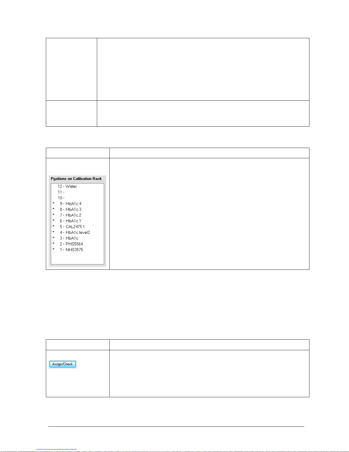
Chapter 03 – SOFTWARE DESCRIPTION
CYANExpert 130 User Manual Rev.02, May 2014 Chapter 3, Pag e 35
Cal. Exp. The number of days left before the calibration expires.
E.g. “10” indicates that the calibration is valid for another ten days. Furthermore, the
calibration is automatically scheduled to be run at the end of this period. “–5” indicates that
the calibration expired five days ago. A small, red square () is visible next to this negative
number. By placing the mouse pointer over it, a text message appears, informing the date
that the calibration was programmed to be run.
Please note that the calibration validity period can be set in Parameters - Methods:
“Calibration Stability (# of days)”.
Controls A check mark will automatically appear for those controls programmed in the currently-in-
use reagents configuration (see 3.4.3). It can also be manually activated or deactivated.
Attention: Expired controls (past expiration date) will not be shown.
B. Position Area
Item Description
Positions on Calibration
Rack
This is a list of the positions in the rack with the calibrators and controls. The positions
are assigned using the Assign/Check button. The rack has 12 positions; the 12
th
is by
the instrument specifications reserved for distilled water to be used for carrying out
the RBL. The running of the controls can be confirmed by the operator by either
checking or not the relative boxes (see picture above). After assigning and confirming,
the occupied positions are marked with *.
Note: Automatic rerunning of the Controls
There is the possibility to rerun a control after a determined time interval. This continuous rerunning of a
control can be useful whenever relatively unstable or extremely sensitive solutions are tested, in order to
verify the reliability of the results.
The automatic rerunning of the controls should be programmed in Parameters – Methods – Dynamic
Controls (min).
C. Assign/Check Area
Item Description
Assign/Check
This button allows the operator to assign positions to the calibrators and the controls
in the calibration rack.
First make sure that the automatic/manual selection of the items in the Selection area
has been carried out correctly. Make any necessary changes and then click
“Assign/Check”. A calibration request message will appear informing the user of the
number of operations already assigned:
Page 62
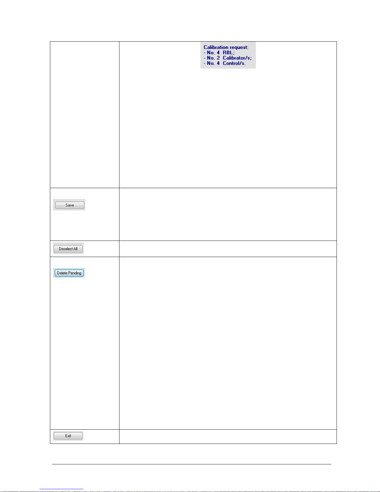
Chapter 03 – SOFTWARE DESCRIPTION
CYANExpert 130 User Manual Rev.02, May 2014 Chapter 3, Pag e 36
Warnings!
It is not possible to carry out this “Assign” procedure for already assigned
calibrators or for expired calibrators.
If calibrators with dilutions are assigned, please make sure that there is enough
liquid volume to carry out the operation set-up. Also verify that the concentration
percentage of the master calibrator is not too low with respect to the predilution
volumes set-up in the methods programming mask. If either of these two
situations occurs, the program will inform the operator with a text message
coloured red when he attempts to assign the calibrators for calibration. Moreover,
no procedure will be carried out for that calibrator.
Remark:
A master calibrator occupies only a single position, regardless of the points contained,
while other multipoint calibrators occupy all those positions previously declared in the
programming mask.
Confirmation
To confirm calibration, click “Save”. This button is activated only after positions have
been assigned. Clicking “Save” automatically closes the viewed window.
Remark:
The operator can print a list of the items assigned and confirmed for calibration and
control. Select the items to be printed from the Checks - Reagents Volume list, and
click the print button.
To deselect the “Run” of all calibrators and controls at once.
Editing a calibration
If the operator returns to the “Calibration and Q.C Setup”, after having assigned and
confirmed a calibration, the following text message will appear to inform that a
programmed calibration already exists: CALIBRATION PENDING!
At this point, the names of the calibrators and of the controls in the calibration rack
and in the calibration table are no longer coloured blue, but in black.
It is still possible to add RBL, calibrators and controls not previously requested, as long
as there are still free positions left in the calibration rack. However, it is not possible to
remove elements from an already programmed calibration.
It is only possible to completely cancel the entire already programmed calibration
by using the “Delete Pending” button, which is activated only when there is a
calibration pending. By clicking “Yes”, the pending calibration(s) are deleted, and the
calibration is no longer valid. Click “No” to annul the request to delete.
To close the Calib. and Q.C. Setup and return to the system monitor.
Page 63

Chapter 03 – SOFTWARE DESCRIPTION
CYANExpert 130 User Manual Rev.02, May 2014 Chapter 3, Pag e 37
1.5.5 CALIBRATION RESULTS
Select Routine and from the options listed, click Calibration Results.
This window contains all results and associated data of the calibrations. It is divided into two sections, a Main Area
and a Details Area. It also contains command buttons.
The following commands are active, for more information on the command buttons, see paragraph 3.1.5.:
Print button to print the selected data
Graph button to view the absorbance graph of the test selected in the Details area
Rerun button to repeat the tests selected in the Details area
Edit button to modify the results of the absorbance, the calculation model or the obtained factor of
the calibrator selected in the Main area (please see NOTE: Edit a calibration curve p41).
A. Main Area
Item Description
Test Name The name of the method.
RBL days
The number of days since the last RBL was performed. A small symbol (
■
) indicates the
presence of a message to be read, which can be accessed by pointing the mouse at this symbol
(please see the section: Calibration – RBL Expiration).
Flags Informs if any errors occurred during the running of the RBL.
The Flags field is present twice more, indicating if an error has occurred during the running of
the calibrators and/or during the reading of the controls.
When an error did occur, all the fields regarding that item are automatically shown coloured
red. Errors are signalled using letters which stand for the type of error encountered – as
A.Main Area
B.Details Area
Page 64
Chapter 03 – SOFTWARE DESCRIPTION
CYANExpert 130 User Manual Rev.02, May 2014 Chapter 3, Pag e 38
reported in Report Options - Flags Description.
D Indicates, by using either the number 1 or 2, the first or second row of data referring to either
differential or bichromatic methods.
Abs The optical density values obtained for the RBL.
This Abs field is present a second time to report the optical density values obtained for the
calibrators.
In the event of replicates (from 2 to 4) the program will automatically calculate the average of
the valid readings and in case of 3 or 4 replicates the program will eliminate the reading
furthest from the average and recalculate the average. The mean value obtained will then be
reported in this field. The separate absorbance values of the replicates can be viewed in the
Details area where the operator can also consult the graph.
Rate Represents reagent mobility during the reaction time, expressed in absorbance.
CAL days
The number of days since the last calibration was performed. A small symbol (
■
) indicates this
calibration execution date, when pointing the mouse at this symbol (please see the section:
Calibration – CAL Expiration).
Refer. The concentration of the calibrator defined in Parameters - Calibrators. In the event of a multi-
point calibration, all reference values are given.
CV % The coefficient of variation percentage among replicates of the calibrator considered valid with
respect to the mean.
Factor The calculated calibration factor.
Result The results obtained for the control.
Mean The mean target value of that control defined in Parameters - Controls.
Reference The range considered normal for that control defined in Parameters - Controls.
B. Details Area
The RBLs, calibrators or controls programmed, but not yet performed, for calibration are shown on top of this area
and are highlighted by a yellow background. Once calibration is performed, this area allows the operator to view
the details of the results regarding the method selected in the Main Area.
Item Description
Type The type of measurement requested (RBL, CAL or Control).
Pos The position occupied within the CAL/CTRL rack.
Name The name of the calibrator or control.
Lot The lot number defined for that calibrator or control.
Abs The measured optical density.
Ref/Res. The results obtained for the control or the defined reference value for the calibrator.
Unit The measurement unit used for that method.
Factor The calculated calibration factor.
Flags Shows if any errors occurred during operation. If an error occurred, a letter and a small red
square (
■
) appear in the Flags field. If the operator passes over this symbol with the mouse, a
text message will appear indicating the full name of the error encountered. Errors are signalled
using letters which stand for the type of error encountered – as reported in Report Options Flags Description.
Page 65
Chapter 03 – SOFTWARE DESCRIPTION
CYANExpert 130 User Manual Rev.02, May 2014 Chapter 3, Pag e 39
Date The date the RBL/CAL/CTRL was performed or assigned and confirmed.
Time The exact time the RBL/CAL/CTRL was performed or assigned and confirmed.
User The user that assigned and/or performed the RBL/CAL/CTRL.
NOTE: Edit a calibration curve (of a multipoint calibration)
To edit the calibration curve, select the requested calibrator from the Main Area of the calibration results list and
click on the Edit button.
A window will open containing a graphic illustration of the results of the calibration and information regarding the
mathematical procedure for calculating the results. The name and the date of the calibration are shown in the
heading of the mask. The window is divided into three sections.
A. Main Area
This area contains the graphic representation of the calibration curve of the selected calibrator. The ordinate axis
(Y) shows data regarding optical density; and the abscissa (X-axis), data concerning concentration. All readings are
indicated as points on the graph. The equation used for calculating the data is provided at the top of the Graph.
B. Details Area
1. A table on the left-hand portion, containing data for each point of the calibrator:
Item Description
Reference The reference value of the concentration as defined for that calibrator.
O.D. (abs) The value of the measured optical density.
CV % Indicates the coefficient of variation percentage among replicates of the calibrators considered
valid with respect to the mean.
Flags Reports if any errors occurred during operation. Errors are signalled using letters which stand
for the type of error encountered – as reported in Report Options - Flags Description.
Recalculated The new calculated value obtained with relation to the type of calculation algorithm.
B. Details Area
A. Main Area
C. Edit Area
Page 66
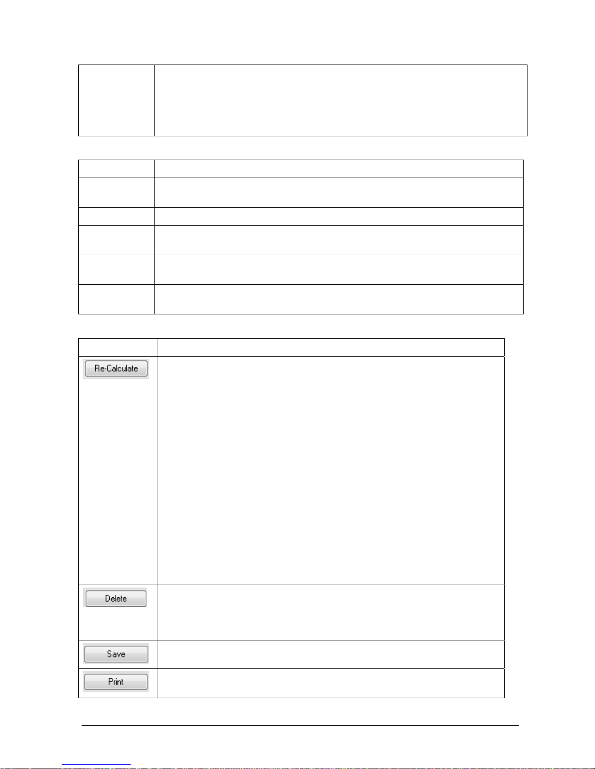
Chapter 03 – SOFTWARE DESCRIPTION
CYANExpert 130 User Manual Rev.02, May 2014 Chapter 3, Pag e 40
% Error The % of error between the value defined by the operator in the reference field and that given
in the recalculated field. This can be used to check whether the chosen calculation algorithm is
a good one.
Absolute Error Indicates the absolute error obtained between the value defined by the operator in the
reference field and that shown in the recalculated field.
2. On the right-hand portion:
Item Description
Calculation
Model
Contains a pull-down menu offering the various calculation types available for the calibrator.
Factor This field is activated only for tests defined by a factor as calculation model.
STD. Dev. Value that indicates the deviation of the curve with respect to the points of that calibrator
(lower values indicate a better calculation model).
Absorbance The operator can insert in this field an optical density value in order to verify and check the
concentration that would be obtained based on the curve.
Result The result for the absorbance inserted (above), obtained after clicking Re-Calculate. This value
will be represented by a red circle in the graph.
C. Edit Area
Item Description
This button allows the operator to edit the obtained calibration data or perform a test. If,
after calibration, the operator believes that anomalies have occurred or that the
calculation model, previously set-up in the Methods mask, does not truly satisfy the
reaction, the calibration can be adapted by making a new calculation of the
concentration of the calibrator. Do one of the following and click Recalculate.
Change the insert values in the O.D. (abs) field. Please note that this will
automatically cause the program to signal an E in the Flags field.
Select a different calculation model.
Change the factor (activated only for tests defined by a factor as calculation
model).
Calculate the result for an inserted absorbance value (test).
Note:
If the data inserted in the fields is not correct, (e.g. in the O.D. (abs) field), and the
resulting curve is different from the requested calibration curve, the program will
indicate those points of the calibration curve, which do not coincide with the requested
curve. Moreover, the following text message will appear in the upper portion of the
mask: “CALCULATION ERROR”.
To delete a point in a calibration curve, first select the point from the table containing all
the points of the calibration curve and then click “Delete”. The instrument will open a
dialog box requesting confirmation of the delete procedure. By clicking “Yes”, the point
will be deleted from the calibration curve. Click “No”, to annul the delete procedure.
In order to memorize and use the settings programmed in this mask, click “Save”.
To print the graph and the associated data. This button is deactivated during editing,
but is automatically reactivated once the edited data has been saved.
Page 67

Chapter 03 – SOFTWARE DESCRIPTION
CYANExpert 130 User Manual Rev.02, May 2014 Chapter 3, Pag e 41
1.5.6 QUALITY CONTROL RESULTS
Select Routine and from the options listed, click Q.C. Results. The following window opens automatically.
Select from the pull-down menus which data you wish to view. Select a certain control or all controls for a certain
test. View all data of a certain day, month or time range and insert the date(s).
This window contains all results and associated data of the quality controls. It is divided into two sections, a Main
Area and a Details Area. The information provided in the Main area depends on the time interval and data
organisation (per control or test) chosen.
A. Main Area
Item Description
TEST Name The name of the method and the associated unit of measurement programmed.
CONTROL Name The name of the control, lot number and expiration date.
REFERENCE Mean The mean reference value as defined in Parameters - Controls.
A. Main Area
Page 68

Chapter 03 – SOFTWARE DESCRIPTION
CYANExpert 130 User Manual Rev.02, May 2014 Chapter 3, Pag e 42
REFERENCE SD The standard deviation of the reference value defined in Parameters – Controls.
DISTRIBUTION Mean The mean of the values measured for that control and test.
DISTRIBUTION SD The standard deviation of the values measured for that control and test.
DISTRIBUTION CV% The coefficient of variation % of the values measured for that control and test
SUMMARY Total The total number of measurements for that control and test.
SUMMARY Min The minimum value measured for that control and test.
SUMMARY Max The maximum value measured for that control and test.
SUMMARY Range The range between the values measured for that control and test.
B. Details Area
Item Description
Position The position occupied in the calibrator/control rack.
Cuv. The cuvette used for the measurement.
Lot # Separate lot numbers.
Abs The absorbance of the selected control.
Result The calculated concentration of the selected control.
Flags Shows if any errors occurred during operation. If an error occurred a character with a small
red square (
■
) appear in the Flags field. If the operator passes over this symbol with the
mouse, a text message will appear indicating the full name of the error encountered. Errors
are signalled using letters which stand for the type of error encountered – as reported in
Report Options - Flags Description.
Date & Time The date en time of measurement of the selected control.
User The user that was logged in when the quality control was performed.
The following commands are active, for more information on the command buttons, see paragraph 3.1.5.:
Print button to print the selected data
Graph button to view the absorbance graph of the selected test
NOTE 1: Deleting (a) Control(s)
The results of the Quality Control can be deleted. Select the result to be deleted in the details area. Right-click with
the mouse. The menu, “Delete the Selected Control(s)”, will automatically appear. Clicking this option will
immediately cause the program to delete all the selected controls.
NOTE 2: TWO MODES OF QUALITY CONTROL GRAPHS
Graph of the optical density: Presents the reading times for results. Select a single row in the Details Area
containing the results you wish to view and then either double click with the mouse or click on the “Graph”
button. This Graph button is activated only when the Details Area contains at least one row of data. Click “Exit”
to return to the Q.C.Results mask.
Page 69

Chapter 03 – SOFTWARE DESCRIPTION
CYANExpert 130 User Manual Rev.02, May 2014 Chapter 3, Pag e 43
Levey-Jennings Plot: Select the required row in the Main Area and at least two rows in the Details Area, and
then click on the “Graph” button.
- In the heading: depends on the chosen data organisation (per control or test) and time interval: the name
of test/control and the date range.
- Left Y-axis: the standard deviations (from –3SD to +3SD)
- Right Y-axis: the relative concentration value. The red line represents the mean value obtained with
respect to the expected mean value.
- X-as: day of the month (date range).
- Green curve: point-to-point connection of points determined as the mean of the measurements of that
day (for visualisation aid only).
- Bottom: the total number of controls, the mean concentration value, the standard deviation and the
coefficient of variation percentage obtained.
Print the graph by clicking the “Print” button. Please note that the graph is monthly and therefore, the printout will be month by month. To close the graph mask, click “Exit”.
1.5.7 RECEIVE FROM HOST
The last item on the Routine Menu is “Receive from Host”. This command allows to activate and then
automatically receive data transmission from the Host. In order to view the item, the user must first select “Host
Connection” in Parameters - Options.
For further information regarding data transmission, see service manual chapter 8 - Host Communication.
Page 70

Chapter 03 – SOFTWARE DESCRIPTION
CYANExpert 130 User Manual Rev.02, May 2014 Chapter 3, Pag e 44
1.6 ARCHIVE
To view and analyse the filed data and to perform “Backup” and “Restore” operations. These two files can only be
used with this program. They are not compatible with any other analyser.
Patients: To view the archived results of the tests performed on patient samples.
Calibrations: To view the archived results of all the calibrations performed.
Backup: To make a copy of the results on an external data storage device.
Restore: To replace data back onto the Archive from an external data storage device.
Test counter: To view the total number of tests carried out, subdivided into groups (RBL, CAL, CTRL and
Samples).
Events and Admin logs: Records all anomalous events involving instrument status.
1.6.1 PATIENTS
This window allows viewing the archived data of previously performed patient samples, selected by indicating the
search criteria.
Select Archive and from the options listed, click Patients. The following window opens automatically.
Insert the desired search criteria. Click “OK” to confirm the selection. The program will pull up all the data
contained in the Archive that match the entered criteria (AND-AND relation). To annul the selection, click “Exit”.
Page 71

Chapter 03 – SOFTWARE DESCRIPTION
CYANExpert 130 User Manual Rev.02, May 2014 Chapter 3, Pag e 45
The requested information is given in a Main Area and a Details Area. The following commands are active, for
more information on the command buttons, see 3.1.5.
Sort button to reorder the viewed data.
Print button to print the selected data.
Graph button to view the absorbance graph of the test selected in the Details area.
A. Main Area
Item Description
! Indicates a STAT sample.
Rack-Cup The number of the rack and the position in that rack of the given sample.
Type The type of sample.
Sample Dilution The predilution ratio.
SID The sample’s identification number.
PID The patient’s identification number.
Name The name of the patient.
Sex and Birthdate The sex and date of birth of the patient.
A. Main Area
B. Details Area
Page 72

Chapter 03 – SOFTWARE DESCRIPTION
CYANExpert 130 User Manual Rev.02, May 2014 Chapter 3, Pag e 46
B. Details Area
Item Description
Test The name of the test carried out.
PreDil & Test Dil The predilution and dilution ratio of the sample.
Result The results obtained.
Unit The measurement unit used for that test, as defined in the methods parameters.
Normal Values The normal range of values for the performed test.
Flags Shows if any errors occurred during operation. If an error occurred a character with a small
red square (
■
) appear in the Flags field. If the operator passes over this symbol with the
mouse, a text message will appear indicating the full name of the error encountered. Errors
are signalled using letters which stand for the type of error encountered – as reported in
Report Options - Flags Description.
Date & Time The date and exact time the test was performed.
User The user logged-in when the test was performed.
1.6.2 CALIBRATION
This window allows viewing the data of previously performed calibrations, selected by indicating the search
criteria.
Select Archive and from the options listed, click Calibration. The following window opens automatically.
Insert the desired search criteria. Click “OK” to confirm the selection. The program will pull up all the data
contained in the Archive that match the entered criteria. To annul the selection, click “Exit”.
The requested information is given in a Main Area and a Details Area. The following commands are active, for
more information on the command buttons, see 3.1.5.
Sort button to reorder the viewed data.
Print button to print the selected data.
Graph button to view the absorbance graph of the selected test.
Page 73

Chapter 03 – SOFTWARE DESCRIPTION
CYANExpert 130 User Manual Rev.02, May 2014 Chapter 3, Pag e 47
A. Main Area
Item Description
Test The name of the test carried out.
Total The total number of tests performed for that calibration procedure.
RBL The number of RBLs carried out for that test.
Cal The number of calibrators performed for that test.
Ctrl The number of controls performed for that test.
First & Last Date The time-window for the data contained in the database for that test.
B. Details Area
Item Description
Type The type of item considered.
Pos The position occupied by that item within the rack dedicated to calibration.
Name The name of that item.
Lot The lot number assigned to that item.
Abs The optical density measured.
Ref./Res. The reference value for the calibrators and the result obtained for the controls.
Unit The measurement unit used.
Factor The factor resulting from the calibration procedure for that test.
Flags Shows if any errors occurred during operation. If an error occurred a character with a small
A. Main Area
B. Details Area
Page 74

Chapter 03 – SOFTWARE DESCRIPTION
CYANExpert 130 User Manual Rev.02, May 2014 Chapter 3, Pag e 48
red square (■) appear in the Flags field. If the operator passes over this symbol with the
mouse, a text message will appear indicating the full name of the error encountered.
Errors are signalled using letters which stand for the type of error encountered – as
reported in Report Options - Flags Description.
Date & Time The date and exact time the test was performed.
User The user logged-in when the test was performed.
1.6.3 BACKUP
This window allows making a copy of the data contained in the Archive. This data can be saved for future
reference or reinserted in the Archive at a later date (please see the Archive – Restore description).
Select Archive and from the options listed, click Backup. The following window opens automatically.
Item Description
Month to backup The data are organized by the program under monthly headings. Select a month to
backup all that data of that requested time interval.
Automatic Deletion
If this field is “checked” (), the program will automatically delete the data from the
Archive at the same time it performs the Backup procedure.
Backup to file Select the folder name and location to which the data have to be transferred.
Moved/ Deleted/
Work
The total number of patients and results copied. If the auto delete is checked, this area will
also indicate the total number of results eliminated from the archive.
OK To confirm the backup.
Exit To exit the Backup mask and return to the System Monitor main screen.
1.6.4 R
ESTORE
This window allows recopying data back into the Archive. These data are copied from the memory device that was
previously used for performing a Backup, and are hereby reinserted into the program, where they can be accessed
for reference and/or for performing various other operations.
Page 75

Chapter 03 – SOFTWARE DESCRIPTION
CYANExpert 130 User Manual Rev.02, May 2014 Chapter 3, Pag e 49
Select Archive and from the options listed, click Restore. First browse and select the file the data you want to
restore. Then, the following window opens automatically.
To perform a restore, select the requested file in the window and open it. The file will automatically be restored
into the archives. To exit the mask, click Exit.
1.6.5 TEST COUNTER
This mask provides information regarding all various operations. It presents the sum of all the tests performed.
Select Archive and from the options listed, click Test Counter.
Item Description
Test The name of the test performed.
Total How many times that particular test was performed, total of all operations.
RBL How many RBLs (Reagent Blanks) were carried out for that specific test.
Cal The total number of calibrators carried out for that particular test.
Page 76

Chapter 03 – SOFTWARE DESCRIPTION
CYANExpert 130 User Manual Rev.02, May 2014 Chapter 3, Pag e 50
Ctrl The total number of controls carried out for that particular test.
Sample The number of samples performed for that particular test.
First & Last Date The dates on which that particular test was first and last run.
The following commands are active:
Sort button to reorder the viewed data.
Print button to print the selected data.
1.6.6 EVENT LOG
Select Archive and from the options listed, click Event Log.
This window logs all those events/occurrences judged to be anomalies which are encountered during instrument
operation. Said anomalies can be either:
Warning! – identified by a yellow triangle
Fatal Error! – identified by a red X-sign
This mask also describes the type of the anomaly encountered, a brief description and the date and exact time of
the registered event.
1.6.7 ADMIN LOGS
This window logs all those events/occurrences from all the different user profiles.
Select Archive and from the options listed, click Admin Logs. This mask is only accessible when the administrator
is logged on. The following mask will open. The administrator can indicate the time interval from which he wants
to see all the data. By clicking OK, all the actions of all the users will be indicated, with their respective time and
date.
Page 77

Chapter 03 – SOFTWARE DESCRIPTION
CYANExpert 130 User Manual Rev.02, May 2014 Chapter 3, Pag e 51
1.7 PARAMETERS
This mask describes the system configuration. Each specific operation to be performed has its own set of
parameters that can be defined. It is not possible to change the parameters while the instrument is in operation.
Methods: To set-up the methods. For more detailed information, please see Chapter 05 – Methodology.
Reagents ID: To set-up the reagent ID codes for barcode reading.
Profiles: To set up the profiles with their respective tests.
Ratio: To set-up the ratios and their respective parameters.
Calibrators: To program the calibrators, along with their relevant tests.
Controls: To program the controls and their relevant tests.
Options: To define the system’s default settings.
Sampling order: To decide the analysing order of the tests programmed for a sample.
Print order: To decide the order in which the results of the various analyses will be printed out, regardless
of the order in which the tests were carried out.
Report options: To define the Header Text of the Report print-out and the error symbols that will be used
therein.
Accounts: To define user IDs and their passwords. In this mask, it is possible to make certain restrictions
regarding the entrance and changeability of these menus.
1.7.1 REAGENTS ID
This function allows to program the reagents ID and on-board reagent stability for use with the barcode reader.
This option is only available when the reagent barcode reader is activated in the option menu (see 3.7.6).
Select Parameters and from the options listed, click Reagents ID.
Item Description
Test
All methods currently programmed in the software. See Parameters Methods.
Reagent All reagents codes (Rgt. Code) currently programmed in the parameters section of the
Page 78
Chapter 03 – SOFTWARE DESCRIPTION
CYANExpert 130 User Manual Rev.02, May 2014 Chapter 3, Pag e 52
test methods. See Parameters Methods.
ID To insert the reagent ID used on the reagent barcode. This code should be exactly 4
digits or a warning will appear in the lower part of the window. See note at paragraphe
3.7.6.
Stab. (days) To insert the ‘on-board’ stability of the reagents on the analyzer plate.
Exit To close the mask.
Save To save the inserted data.
Print To print the method list with reagent ID’s and stability.
1.7.2 PROFILES
This function allows to program test profiles, (i.e. predetermined groups of analysis to be carried out together).
There is no limit to the number of profiles the user can define.
Select Parameters and from the options listed, click Profiles.
Section Description
Profiles List List of the profiles programmed, listed in alphabetical order.
Details List of the methods programmed in the “Methods” mask, listed in alphabetical order.
Page 79
Chapter 03 – SOFTWARE DESCRIPTION
CYANExpert 130 User Manual Rev.02, May 2014 Chapter 3, Pag e 53
Whenever the user selects a profile from the “Profiles List”, the methods that are included in that profile are
automatically displayed. The methods that make up a profile are checked ().
Item Description
Add Profile To add a new profile to the profiles list.
Delete Profile To delete a profile from the profiles list.
Save To save the setup of a new profile.
Print To print a profile selected from the profiles list.
Exit To close the mask.
ADDING A NEW PROFILE TO THE PROFILES LIST
The button allows the user to create and add a new profile to the “Profiles List”.
To add or create a new profile, proceed as follows:
Click on “Add Profile”. The “Add Profile” dialog box will appear where the user can enter the name of the
profile (maximum: 12 alphanumeric characters).
Confirm the name by clicking “OK” (clicking on “Exit” will cancel the “Add” operation). The new profile will
be listed along with the other already existing profiles.
Page 80
Chapter 03 – SOFTWARE DESCRIPTION
CYANExpert 130 User Manual Rev.02, May 2014 Chapter 3, Pag e 54
Select the required methods in the “Details”-area, by ticking the respective check-box.
Click on “Save”.
DELETING A PROFILE FROM THE “PROFILES LIST”
The button allows the user to delete an entire profile from the “Profiles List”.
To delete a profile, proceed as follows:
Select the profile to be deleted from the “Profiles List”.
Click on “Delete”. A “Delete” dialog box will open.
Click “Yes” in the dialog box to confirm (clicking “No” will cancel the “Delete” operation).
ADDING/DELETING METHODS TO/FROM A PROFILE
To add a method to and/or delete a method from an existing profile, proceed as follows:
Select the profile to be edited in the “Profiles List”.
Select/deselect the method(s) to add to/remove from the “Details List”.
Confirm the changes made by clicking on “Save”.
PRINTING A PROFILE
The button allows the user to print a profile selected from the “Profiles List”.
To print a profile, proceed as follows:
Select a profile from the “Profiles List”.
Click on “Print”.
1.7.3 RATIO
This function allows the user to program test ratios. A ratio is a method which is the mathematical result of
previously defined methods. There is no limit to the number of ratios the user can define.
Select Parameters and from the options listed, click Ratio.
A. Description Area
B. Calculation Area
C. Operative Area
Page 81

Chapter 03 – SOFTWARE DESCRIPTION
CYANExpert 130 User Manual Rev.02, May 2014 Chapter 3, Pag e 55
The mask is divided into three areas, the Description area, the Calculation area and the Operative area.
A. Description Area
Item Description
Description The name of the programmed ratio. This field can contain a Maximum of 20 characters.
Unit The unit used for representing the values of the ratio.
Decimals How many decimal places are to be included in the ratio values. This selection is made from
the field’s pull-down menu, by selecting from a Minimum of 0 to a Maximum of 3.
LIS Code The acronym (max 6 characters) used for the serial data transmission of the result.
Reference
Range
A table containing the reference values regarding the test. They are divided into the following
categories: Low, Normal, High, according to the sex and age of the subject. For more details
information, please see chapter 05 – Methodology.
Values inserted for Male subjects are automatically entered into the Female and Child
category areas as predefined values. However, the operator can choose other values for these
two categories and insert them into the appropriate fields.
B. Calculation Area
Item Description
Calculation
Model
A pull-down menu automatically appears whenever this field is selected and offers six options:
1. A-B
2. A/B
3. A / (B-C)
4. (A+B) - (C+D)
5. (A-B) – (C/D)
6. (A+B) / C
These letters refer to the tests selected for the calculation and include multiplicative
coefficients.
When one of the four fields is selected (A to D – (x1)), a pull-down menu will automatically
open containing the names of the tests which can be selected.
If no test has been selected for that field, this field is not activated and will appear coloured
light grey – the activated fields appear coloured blue.
Expression To view the programmed ratios. Please note that in this field the LIS Code of the selected
Tests are shown.
Page 82

Chapter 03 – SOFTWARE DESCRIPTION
CYANExpert 130 User Manual Rev.02, May 2014 Chapter 3, Pag e 56
C. Operative Area
This section includes the operative buttons necessary for carrying out following operations:
ADDING A NEW RATIO TO THE RATIO LIST
The button allows the user to create and add a new ratio to the “Ratio List”.
Click on “Add”. The “New Test” dialogue box will appear where the user can enter the name of the ratio.
Confirm the name by clicking on “OK”; click “Exit” to cancel the “Add” operation.
Fill in the description area.
Enter the calculation area and indicate the calculation model with its respective methods.
Click “Save”.
Pay attention:
1. Never use a ratio name already used. An error message will appear on the main screen in order to change
the ratios name.
2. To edit a ratio: select the ratio in the Ratio List, edit as requested and click “Save”.
DELETING A RATIO FROM THE “RATIO LIST”
The button allows the user to delete an entire ratio from the “Ratio List”.
Select the ratio to be deleted from the “Ratio List”.
Click on “Delete”. A “Delete” dialogue box will open.
Click “Yes” in the “Delete” dialogue box to confirm (“No” will cancel the “Delete” operation).
1.7.4 CALIBRATORS
This mask allows the user to program the calibrators along with the relevant methods.
Select Parameters and from the options listed, click Calibrators.
The mask is divided into three areas, the Description area, the Details area and the Operative area.
A. Description Area
This area contains a list of the programmed calibrators, listed in alphabetical order.
If a calibrator is selected from the list, the methods associated with that calibrator along with their relative values
are automatically displayed in the Details area.
Page 83
Chapter 03 – SOFTWARE DESCRIPTION
CYANExpert 130 User Manual Rev.02, May 2014 Chapter 3, Pag e 57
B. Details Area
This area contains the details of the calibrators and the values for the individual methods.
Field Description
Lot Number The lot number of the calibrator.
Expiration The expiration date of the calibrator.
Warning! Once the calibrator has expired, it will no longer be viewed.
Prediluted Activating (checking) this field indicates that the calibrator is already prediluted. The instrument
will treat the calibrator differently from the samples. To measure the calibrator, no dilution will be
made as setup in the method. By deactivating field, the instrument will apply to the calibrator the
same dilution as that of the method (if there is one). For Master calibrator and for more details,
please see Chapter 06 – Calibration curves.
Diluent The name of diluent used (only visible in case of a Master calibrator).
The lower portion is dedicated to the methods associated with the calibrator. The table gives the unit
programmed for the method, the number of replicates requested, the CV% and reference values (expressed in
concentration) for the various methods.
C. Operative Area
Button Description
Add CAL To add a new calibrator to the list of calibrators.
Copy as New To copy a selected calibrator, but enter new calibrator details and test values.
Delete CAL To delete a calibrator from the list of calibrators.
Add Tests To add a test to a calibrator included in the list of calibrators.
A. Description Area
B. Details Area
C. Operative Area
Page 84
Chapter 03 – SOFTWARE DESCRIPTION
CYANExpert 130 User Manual Rev.02, May 2014 Chapter 3, Pag e 58
Delete Tests To delete a test from a calibrator included in the list of calibrators.
Print To print one selected calibrator or all calibrators with associated tests.
Save To save the setup of a new or edited calibrator (add/delete methods) previously defined.
Exit To close the mask.
ADDING A NEW CALIBRATOR
(defining the name of the calibrator and its relative data)
Click
, an “Add Calibrator” dialogue box automatically opens.
The user must insert the following data:
Name: name of the calibrator (max: 12 alphanumeric characters)
Lot Number: lot number of the calibrator (max: 8 alphanumeric characters)
Expiration: expiration date of the calibrator. The default date is the current date plus one year. The user can
open a calendar by pressing F4 or double clicking with the mouse, or can simply edit the date by digiting a
new date on the place of that one given.
Warning! Once the calibrator has expired (i.e. after its programmed expiration date), it will no longer
be viewed.
Points: number of points of the calibrator (from 1 to 8 points)
Master: (check-box) if the user ticks this box, he/she defines the calibrator as a Master calibrator This implies
that the instrument will automatically prepare the different calibrations points starting from the Master
calibrator.
Click “OK” to confirm the data; the above defined/added calibrator will automatically be included in the
“Calibrators List”. Clicking on “Exit” will cancel the add calibrator operation.
Warning! The data inserted in this mask cannot be edited or modified in any way. To change any data, the user
must necessarily eliminate (delete) the calibrator and re-add.
ADDING METHODS TO A CALIBRATOR
In order to correctly define a calibrator, the user must associate methods to it.
Select the required calibrator in the “Calibrators List”.
Click on the
button. A multiple-selection window will open including all the methods
programmed in the “Methods” mask.
Note: This window contains all those tests available for that particular calibrator and not defined against a
factor. The methods shown are appropriate for the type of calibrator selected; or rather: if the calibrator is
a 1-point calibrator, only those tests defined with “calibrator” as calculation Model (Parameters
Methods) will be listed. If the calibrator requires 2-points or more, then the list will only contain those
methods defined as multipoint calculations.
Page 85
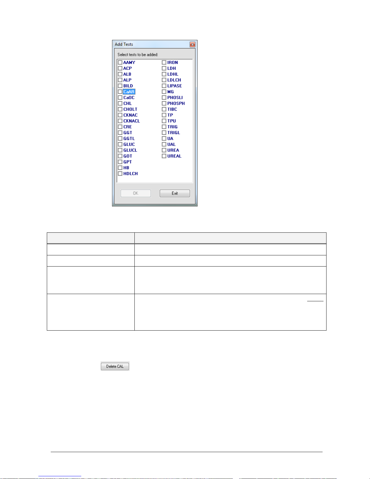
Chapter 03 – SOFTWARE DESCRIPTION
CYANExpert 130 User Manual Rev.02, May 2014 Chapter 3, Pag e 59
Select the method(s) required from among those options offered in the “Add tests” menu.
Click “OK” to confirm the method(s) chosen; clicking “Exit” will cancel the selections made.
Define for each of the previously selected method(s) the following configuration parameters:
Field Description
Replicates The number of replicates to be executed for the calibrator
CV % The coefficient of variation percentage among the replicates
Ref.1,…Ref.n
(the number of points can range
from “1” to “6”)
Reference values expressed in concentration (necessary for mapping the
calibration curve) (if NOT a Master calibrator).
Conc.
Ref.1%...Ref.n%
(the number of points can range
from “1” to “6”)
Reference values expressed in percentages of the concentration of the Master
calibrator.
To save the data related to new calibrators or editing of already exiting calibrators, click “Save”.
DELETING A CALIBRATOR FROM THE CALIBRATORS LIST
Select the calibrator to be deleted from the “Calibrators List”.
Click on the
button. The “Delete Calibrator” dialogue box will automatically open.
Confirm the deletion request by clicking “Yes”; clicking “No” will cancel the delete operation.
Page 86

Chapter 03 – SOFTWARE DESCRIPTION
CYANExpert 130 User Manual Rev.02, May 2014 Chapter 3, Pag e 60
DELETING A METHOD (OR MORE THAN ONE METHOD) FROM A CALIBRATOR
Select the calibrator from the “Calibrators List”
Click on the
button.
The “Delete Tests” dialogue box will automatically open.
Select the method(s) to be deleted from among the choices offered in the “Delete Tests” window.
Confirm the deletion of the method(s) from the required calibrator by clicking on “OK”; clicking on “Exit”
will cancel the delete test operation.
“PRINT” BUTTON
Clicking “Print” allows printing one calibrator selected in the “Calibrators List”, along with its details (Press “Yes”)
or to print all calibrators with associated details (Press “No”). Press “Cancel” to close the window without printing.
“EXIT” BUTTON
Clicking “Exit” allows closing the mask and returning to the “System Monitor” mask.
1.7.5 CONTROLS
This mask allows the user to program the quality controls along with the relevant methods.
Select Parameters and from the options listed, click Controls.
A. Description
Area
B. Details Area
C. Operative Area
Page 87
Chapter 03 – SOFTWARE DESCRIPTION
CYANExpert 130 User Manual Rev.02, May 2014 Chapter 3, Pag e 61
The mask is divided into three areas, the Description area, the Details area and the Operative area.
A. Description Area
This area contains a list of the programmed controls, displayed in alphabetical order.
When a control is selected from the list, the methods associated with that control along with their values are
automatically displayed.
B. Details Area
This area is dedicated to the details to set up the controls and the values of the individual methods.
The below-listed fields are included in the upper portion of this area.
Field Description
Lot Number The lot number of the control.
Expiration The expiration date of the control.
Warning! Once the control has expired, it will no longer be viewed.
Prediluted Activating (checking) this field indicates that the control is already prediluted. The instrument will
treat the control differently from the samples. To measure the control, no dilution will be made as
set up in the method. By deactivating this field, the instrument will apply to the control the same
dilution as that of the method (if there is one).
Diluent The name of diluent used (if the Method programming requires a dilution).
The lower portion is dedicated to the methods associated with the control.
Field Description
Test Short name (abbreviation/acronym) of the method.
Unit The unit programmed for that method.
Min. Value Minimum reference value of the control for the associated method.
Max. Value Maximum reference value of the control for the associated method.
Mean Mean value calculated on the minimum and maximum reference values of the control
(calculated automatically).
SD Standard Deviation of the minimum and maximum reference values of the control
(calculated automatically).
C. Operative Area
Button Description
Add CTRL To add a new control to the list of controls.
Copy as New To copy a selected control, but enter new control details and test values.
Delete CTRL To delete a control from the list of controls.
Page 88
Chapter 03 – SOFTWARE DESCRIPTION
CYANExpert 130 User Manual Rev.02, May 2014 Chapter 3, Pag e 62
Add Tests To add a test to a control included in the list of controls.
Delete Tests To delete a test from a control included in the list of controls.
Print To print one selected control or to print all controls with associated tests.
Save To save the setup of a new control or an edited control (add/delete methods) previously
defined.
Exit To close the mask.
ADDING A NEW CONTROL
(defining the name of the control and its associated data)
Click
, a “New Control” dialogue box automatically opens.
The user must insert the following data:
Name: name of the control (max: 12 alphanumeric characters)
Lot Number: lot number of the control (max: 8 alphanumeric characters)
Expiration: expiration date of the control. The default value is the current date plus one year. The user
can open a calendar by pressing F4 or double clicking with the mouse, or can simply edit the date by
digiting a new date in the place of that one given.
Warning! Once the control has expired (i.e. after its programmed expiration date), it will no longer
be shown.
Click “OK” to confirm the data entered; the above defined/added calibrator will automatically be included in the
“Controls List”. Clicking “Exit” will cancel the define/add control operation.
Warning! The data inserted in this mask cannot be edited or modified in any way. To change any data, the user
must necessarily eliminate (delete) the required control and re-add.
ADDING METHODS TO A CONTROL
In order to correctly define a control, the user must associate methods to it:
Select the required control in the “Controls List”.
Click on the
button. A multiple-selection window will open including all the methods
programmed in the “Methods” mask and corresponding to the characteristics of the control.
Select the method(s) required from among those options offered in the “Add Tests” menu.
Click “OK” to confirm the method(s) chosen; clicking “Exit” will cancel the selections made.
Define for each of the previously selected method(s) the following configuration parameters:
Page 89
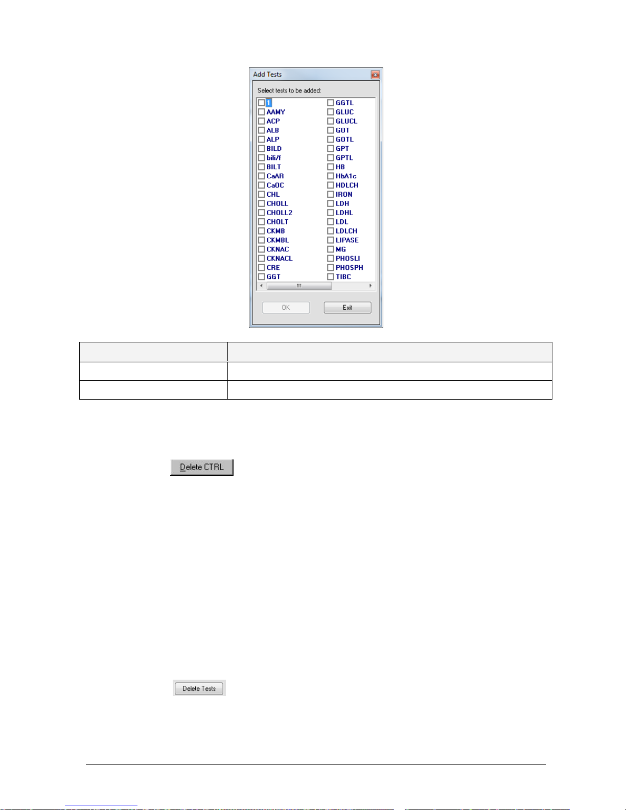
Chapter 03 – SOFTWARE DESCRIPTION
CYANExpert 130 User Manual Rev.02, May 2014 Chapter 3, Pag e 63
Field Description
Min. Value Minimum reference value of the control for the associated method
Max. Value Maximum reference value of the control for the associated method
To save all the data related to the control or the editing of an already existing control, click “Save”.
DELETING A CONTROL FROM THE CONTROLS LIST
Select the control to be deleted from the “Controls List”.
Click on the
button. The “Delete Control” dialogue box will automatically open.
Confirm the deletion request by clicking “Yes” in the “Delete Control” dialogue box; clicking “No” will
cancel the delete control operation.
DELETING A METHOD (OR MORE THAN ONE METHOD) FROM A CONTROL
Select the control from the “Controls List”.
Click on the
button.
The “Delete Tests” dialogue box will automatically open.
Select the method(s) to be deleted from among the choices offered in the “Delete Tests” window.
Confirm the deletion of the method(s) from the required control by clicking “OK”; clicking “Exit” will
cancel the delete test operation.
Page 90
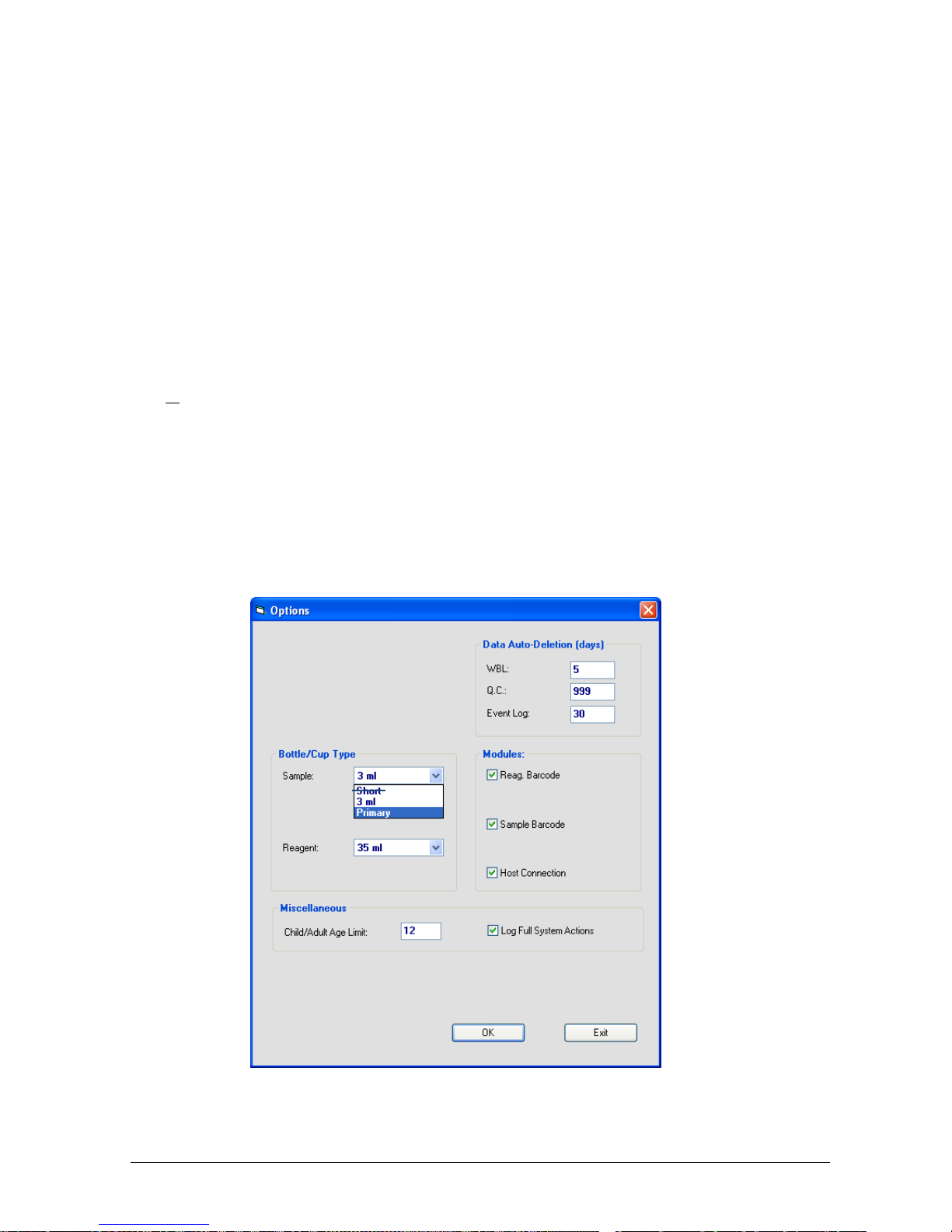
Chapter 03 – SOFTWARE DESCRIPTION
CYANExpert 130 User Manual Rev.02, May 2014 Chapter 3, Pag e 64
“PRINT” BUTTON
Clicking “Print” allows printing one control selected in the “Control List”, along with its details (Press “Yes”) or to
print all controls with associated details (Press “No”). Press “Cancel” to close the window without printing.
“EXIT” BUTTON
Clicking “Exit” allows closing the mask and returning to the “System Monitor” mask.
1.7.6 OPTIONS
This mask allows defining a series of default parameters for the analyser.
Select Parameters and from the options offered, click on “Options”.
Page 91

Chapter 03 – SOFTWARE DESCRIPTION
CYANExpert 130 User Manual Rev.02, May 2014 Chapter 3, Pag e 65
Item Description
Bottle/Cup type
Sample
To set the type of sample containers. It contains a pull-down menu where the operator
can choose either primary or 3 mL (or short).
PAY ATTENTION: To prevent breaking the sample probe, it is extremely important
that these software settings correspond to what is physically put on the plate!
Primary: Can be safely used for BOTH primary tubes (universal) and 3 ml cups
(CY008-C28); however it increases the dead volume for the 3 ml cups. The needle
aspirates up to 26 mm from the primary tube button. These cups can be loaded on
a rack for primary tubes and 3 mL cups (CY008-C02).
3 mL: ONLY for 3 ml cups (CY008-C28) and CANNOT be used for primary tubes.
These cups can be loaded on a rack for primary tubes and 3 mL cups (CY008-C02).
Short: Short cups – Calibrator and control cups (1 mL) (CY008-C22). These CANNOT
be used programmed nor used on the rack for primary and 3mL cups. They need a
special sample rack!
Once the setting has been chosen, it is fixed and the same for the four sample
racks. A combination of different sample cup settings is NOT possible, nor is it
possible to change the cup type sample per sample. The user has to choose the
same option for the 4 racks!!
Bottle/Cup type
Reagent
To declare the default type of container for the reagents. This field contains a pull-down
menu, offering the choice of either 35 mL or 6 mL sizes.
The bottle type can be changed, reagent by reagent, on the reagent plate
configuration (Right-click on reagent name).
PAY ATTENTION: To prevent breaking the sample probe, it is extremely important
that these software settings correspond to what is physically put on the plate!
Child/Adult Age Limit Insert in this field an age limit for defining a patient as either Adult or Child. This age
limit will be used by the program when the normal values range is interpreted.
Data auto-deletion
(days)
These fields make it possible to define for how long the following data must be retained
in memory: WBL, Quality Control and the Event Log. Insert, in the corresponding field,
the number of days for which this data must be kept in the system memory – after
which the data will be automatically deleted.
Reagent barcode
Module
This field must be “checked” (), to insert reagents using a Barcode reader.
Sample barcode
Module
This field must be “checked” (), to insert samples using a Barcode reader.
Host Connection This option allows connecting to the Host and is only visible when a Host computer is
connected to the computer via port COM2. If the command is selected, the user can
view on the System Monitor and in the Routine menu those commands necessary for
receiving and transmitting data.
Log Full System
Actions
To record, in dedicated files, all those system operations useful for identifying the cause
of the problem, whenever unidentifiable instrument errors occur. This field is “checked”
() always, it can be made not active for one run only.
In order to save and use the settings programmed in this mask, click “OK”. Changing the settings is only possible
when the instrument is in the Stand-by status. To exit the Options and return to System Monitor, click “Exit”.
Page 92
Chapter 03 – SOFTWARE DESCRIPTION
CYANExpert 130 User Manual Rev.02, May 2014 Chapter 3, Pag e 66
NOTE 1: BARCODE READER
As soon as these modules are checked in the option menu, you will be able to read barcodes.
1. Sample Barcode
Barcode format
Different formats readable: Code 39, Code 128, Code 2/5, CODABAR.
Up to 16 digits.
Use racks for primary tubes + 3 ml cups.
Place the barcodes visible, thus positioned to the outside of the sample rack.
The barcode label must be placed at least 1 cm from the bottom of the tube.
Barcode use
Click on the button for sample rack replacement and select the sample racks for reading with the
barcode reader.
If the instrument is not connected with the LIS system, the user must enter in the “Worklist Setup” and
select the tests that must be performed for each single sample along with all the additional info (name,
surname, ecc.).
If the instrument is connected to a LIS system, see NOTE 2.
2. Reagent Barcode: Code 39, ratio 31
Barcode format
a. 35 mL container: Length 13 digits
XXXX 1 XXXX MMYY
Reagent ID bottle lot number expiration date
Bottle type 1 or 2 (1 = 35 ml, 2 = 6 ml)
b. 6 mL container: Length only first 4 digits (= reagent ID)
6 mL container is automatically programmed if only 4 digits are read. The other information of lot
number and expiration date is not available.
Barcode use
Verify that the correct reagent ID code (4 digits) are correctly programmed.
Parameters Reagents ID (see 3.7.1).
Read the reagent barcode:
Checks Reagents configuration Barcode button (see 3.4.3).
The following instruction will appear. Remove sample rack “A” and click “OK” to confirm.
Page 93

Chapter 03 – SOFTWARE DESCRIPTION
CYANExpert 130 User Manual Rev.02, May 2014 Chapter 3, Pag e 67
The software will perform a reading of the whole reagent plate or the chosen selected positions and
place the reagents in a ‘locked’ position on the reagent plate.
All test methods related to the detected reagents are automatically selected.
NOTES:
The software will not accept two bottles with the same Reagent ID together on a plate.
If a test needs two or three reagents and one of them is missing from the plate (not read), the software
will NOT select that test.
NOTE 2: HOST or LIS CONNECTION
There are two ways to use the barcode reader in combination with the LIS connection. These options depend on
how the software engineer develops the communication system with the Host computer (see service manual –
Chapter 8 – Host connection).
1. Unidirectional or Manual
If the LIS does NOT support the automatic query at the HOST computer, the user must first download manually all
the sample through the “Worklist Setup” menu. All the samples will be temporarily placed in the “Unassigned
Sample” area. Then the user has to perform the reading of the samples rack (with the barcode reader) and the
software will automatically move the samples from the unassigned area to the worklists.
2. Bidirectional or Automatic
If the LIS supports the automatic query at the HOST computer, the user only has to read the samples rack with the
barcode reader and the software will automatically download the information for each sample.
1.7.7 S
AMPLING ORDER
Select Parameters and from the options listed, click “Sampling order”.
This window allows deciding in which order the tests, programmed for a sample, have to be performed.
The default order can be changed by giving an order number, in the ‘Pos’ area, to the methods, starting from 1
and counting up. Methods still indicated with a 0 will not get any priority and will be examined after the other
tests. To save, click “OK”. The order of the tests can be also printed by clicking on the “Print” button.
Page 94

Chapter 03 – SOFTWARE DESCRIPTION
CYANExpert 130 User Manual Rev.02, May 2014 Chapter 3, Pag e 68
1.7.8 PRINT ORDER
Select Parameters and from the options listed, click “Print Order”.
This window allows deciding in which order the tests are to be printed for the final report, regardless of the order
in which they were carried out. Insert an order number in the ‘Pos’ area to that method, starting from 1 and
counting up. Methods still indicated with a 0 will be printed at the end of the report, in the default order. To save,
click “OK”. The order of the tests can be also printed by clicking on the “Print” button.
1.7.9 REPORT OPTIONS
This mask allows defining the header and symbols that will indicate errors on the report print-out.
Select Parameters and from the options listed, click “Report Options”.
Header Text area, where up to 800 characters can be inserted to make a specific laboratory heading for
the reports. Confirm by clicking “OK”.
Warning message area, containing a Warning message on the right and the flags list with the following
fields on the left:
Page 95

Chapter 03 – SOFTWARE DESCRIPTION
CYANExpert 130 User Manual Rev.02, May 2014 Chapter 3, Pag e 69
Item Description
Group To view the group to which that Flag belongs. Each group has its own symbol, which
indicates the type of Flag (See Chapter 09 – ERROR SIGNALING AND TROUBLE SHOOTING).
Flag Description To see the name setup for that type of error.
Symbol This field contains either a character or a symbol indicating one or more errors. The
characters or symbols inserted will be used in the report print-out to declare that error (See
Chapter 09). To memorize and use the text and any new symbols for the print-out of the
report, click on “OK”. “OK” is activated only after the information contained in this mask has
been edited in some way.
Warning The operator should always consult this message before undertaking any further action
that might compromise the reliability of the test result(s).
Exit To exit the Report Options mask and return to the System Monitor, click “Exit”.
1.7.10 ACCOUNTS
Select Parameters and from the options listed, click “Accounts”. The following window will open automatically.
Note:
The “Create user” and “Users profile” buttons are active only when logged in as “Administrator”. In these
areas the administrator can create specific user profiles and can put some restrictions to the users in order
not to change crucial settings. When working with user profiles, the administrator can check what has
been going wrong and who was working with the analyser during the error. This can be done in the
“admin log” menu under Archives.
Change Password: allows the user to modify his/her own password.
A. Change password
Click on “change password” in the account menu.
Give in the new password and confirm it.
To save, click “Change”. Clicking “Exit” allows closing the mask without saving any changes.
Page 96
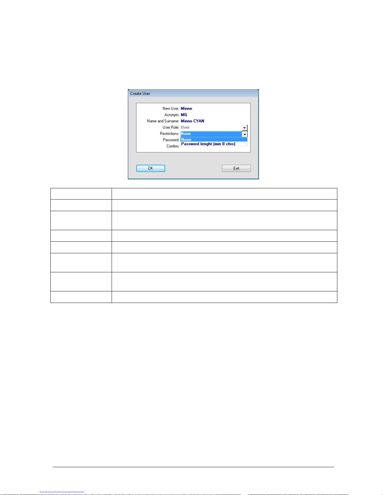
Chapter 03 – SOFTWARE DESCRIPTION
CYANExpert 130 User Manual Rev.02, May 2014 Chapter 3, Pag e 70
B. Create a User
Open the Account menu and click on “Create user”.
Insert the specific personal details for that user and save.
Save by clicking “OK”. To exit without saving, click “Exit”.
Item Description
New User To define the username.
Acronym To define the acronym of the username. This acronym will be shown in the right corner
on the main screen, to indicate who is logged on.
Name and surname To define the name and the surname of the user.
User role “User” as default setting.
Restrictions Indicates whether there are restrictions on the chosen password (cfr. minimum eight
characters).
Password To define the password. This password can be changed by the user itself when he is
logged on.
Confirm To insert the password again as a confirmation.
C. User profile
This mask is used to define what the user can adapt and what is restricted in the settings parameters of the
instrument.
Open the Account menu and click on “User Profile”. The following mask will open.
Select the requested User.
Select the Status Bar. This contains a pull-down menu with the following two options:
1. Active: This way the user is allowed to use the analyser, but some restrictions can be given by the
administrator. When the functions on the “functions list” are not checked (), these functions are
restricted for that user. It implies that the user will not be able to change these parameters. When the
functions are checked (), they are activated for the user.
2. Locked: An account can be locked totally, in case of total restriction of the user using this analyser.
The user will not be able to log-on.
Page 97
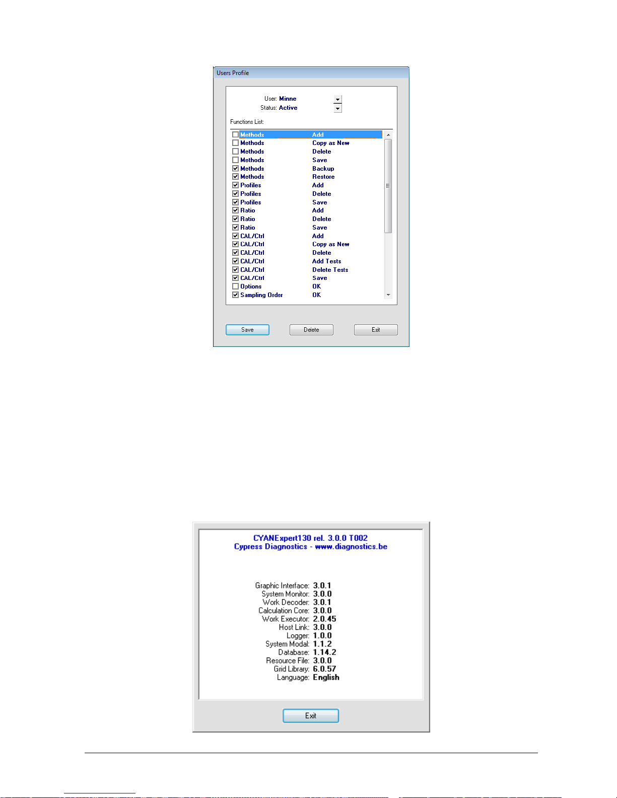
Chapter 03 – SOFTWARE DESCRIPTION
CYANExpert 130 User Manual Rev.02, May 2014 Chapter 3, Pag e 71
1.8 HELP
1.8.1 GUIDE
Not functional
1.8.2 INFO
This mask allows the user to view a list of revisions regarding the installed software components that are installed
in the system the operator is using.
Select “Help” and from the options listed, click “Info”.
To close this window, exit the Info mask and return to the main mask by clicking on “Exit”.
Page 98

Chapter 03 – SOFTWARE DESCRIPTION
CYANExpert 130 User Manual Rev.02, May 2014 Chapter 3, Pag e 72
1.9 LOG OFF
This function allows the user to disconnect from the system. The automatic display of the login dialog box makes
it possible for a new user to connect to the system.
To access the system, enter User ID and Password. To confirm the data entered in the “Login” window, click “Log
On”.
Note: To avoid improper use of the instrument under your own login, please always log off when you are leaving
the laboratory.
Page 99

Chapter 03 – SOFTWARE DESCRIPTION
CYANExpert 130 User Manual Rev.02, May 2014 Chapter 3, Pag e 73
1.10 SHUT DOWN
To exit the program, the operator must first allow the instrument to complete all the running operations.
Clicking on this command causes the following text dialog box to appear:
Clicking “Yes” will cause the program to close and the system to shut down. The operation takes a few seconds,
when the analyser and the computer are linked. When they are not linked the shutting down process will take 4
minutes. Clicking “No”, will annul the request.
When the Shut Down procedure is launched, the Cuvette Plate will change into a clock figure that moves counterclockwise, marking the remaining time till closure of the program.
Once Shut Down is completed, the instrument can either be turned off or left on – in stand-by – ready to be
reactivated for another work cycle.
During Stand-by, the instrument will maintain the following conditions:
Heating of the reaction plate;
Reduced power (voltage) to the photometer lamp.
Page 100

Chapter 04 - DAILY ROUTINE
CYANExpert 130 User Manual Rev.01, Aug 2013 Cha pter 4 Page 1
CHAPTER 04 – DAILY ROUTINE
4.1. DAILY ROUTINE......................................................................................................................................... 2
4.2. STAND-BY FUNCTION ............................................................................................................................ 3
 Loading...