

Page 1

1. Overview
The Cypress Envirosystems Wireless Pneumatic Thermostat (WPT) retrofits an
existing pneumatic thermostat to provide Direct Digital Control (DDC) like zone
control functionality at a fraction of the time and cost without disturbing occupants.
The WPT enables remote monitoring of zone temperature, branch pressure, remote
control of setpoints, and programmable setback or setup of the pneumatic HVAC
systems. It also enables integration with utility Demand Response programs.
The WPT USB Hub (HUSB) is required to connect the WPT wireless network to the
WPT Green Box. One HUSB is required per WPT wireless network. The HUSB is
connected to the WPT Green Box on the USB port.
1.1. Components
The WPT-800-HUSB kit includes the following components:
• HUSB – USB Hub
• Universal wall bracket
• Mounting screws, #6 x 1” self-tapping (x2)
HUSB Installation Manual
Doc No. 910-00003-01 Rev 05
• USB cable
1.2. Prerequisites for Installation
The WPT system relies on a wireless network for communication. The following
tasks must be completed before proceeding to HUSB installation:
• Installation of the WPT Green Box
• Assignment of network ID
Manuals for the WPT, WPT Green Box, HUSB and other manuals related to the WPT
system can be found at http://www.cypressenvirosystems.com/wpt-downloads.php.
1.3. Tools Required for Installation
• Phillips-head screw driver
2. HUSB Installation
The overall HUSB installation procedure includes:
• Mounting the HUSB
• Configuring the HUSB
Page 1 of 6
Page 2
HUSB Installation Manual
Do Not
Doc No. 910-00003-01 Rev 05
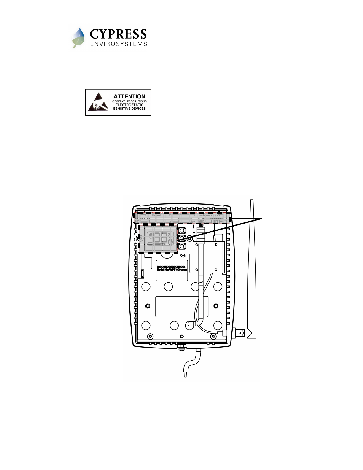
ESD Handling Precautions
Warning!
• The HUSB contains ESD sensitive circuit cards and components, shown in
Figure 1.
• Great care must be exercised while handling the HUSB with the cover open.
• Do not touch any of the circuit boards with fingers or any part of the body.
• Touching the circuit boards may cause the unit to fail due to electrostatic
discharge.
• Hold and handle the unit using the external bottom plastic cover as the
support.
Touch
Figure 1. Handling the HUSB
Page 2 of 6
Page 3

2.1. Mounting the HUSB
1. Mount the universal wall bracket, shown in Figure 2, using the two screws
provided.
2. Mount the HUSB onto the universal wall bracket using the captive screws, shown
in Figure 3.
HUSB Installation Manual
Figure 2. Universal Wall Bracket
Doc No. 910-00003-01 Rev 05
Figure 3. Mounting the HUSB onto the Universal Wall Bracket
3. Connect the USB cable and close the top cover.
4. Connect the other end of the USB cable to the WPT Green Box’s USB port.
Page 3 of 6
Page 4

2.2. Powering On the HUSB
The HUSB is powered through the USB port on the WPT Green Box. To power on
the HUSB, connect the USB Cable to the WPT Green Box’s USB port. The HUSB
turns on and performs initialization. After initialization, the LCD displays either E0 or
the current channel frequency.
The various indicators and characters that are displayed on the LCD display are as
shown in the Figure 4.
The front panel of the LCD display is used to perform diagnostics on the HUSB and
no user information is displayed.
HUSB Installation Manual
Figure 4. LCD Display
Doc No. 910-00003-01 Rev 05
2.3. Configuring the HUSB
The HUSB is factory configured with Network ID 1. If the network ID of the WPT
system is other than 1, the HUSB must be configured with a valid network ID to make
it functional.
Note: HUSB has a blank front cover to prevent accidental changes to the
configuration settings. The front cover has to be removed to gain access to
the display and switches.
Note: The network ID is a single digit number and cannot have a “0” value.
To configure the network ID, perform the following:
1. Press and release all three buttons simultaneously. The HUSB enters
programming mode, shows the network ID and the first digit starts flashing.
The °F icon is displayed, indicating that the network I D is being programmed.
Press and release all three
buttons simultaneously to
enter Programming Mode
Digit will flash when
configuring the Network ID
Page 4 of 6
Page 5

2. Press the top or bottom button to change the network ID to the required value.
The network ID cannot have a “0” value.
3. Press middle button to confirm the network ID.
The HUSB will automatically exit the programming mode if no key is pressed for
one minute.
4. Replace the front cover upon completion of the programming.
5. The network ID can be changed any time by following steps one through four.
When the HUSB is working normally, it will display the network ID currently in use.
3. Troubleshooting
The HUSB is designed with the following diagnostic functions to detect and diagnose
faults:
HUSB Installation Manual
Figure 5. Configuring Network ID
Doc No. 910-00003-01 Rev 05
Code Reason Solution
E2
E3
E4
E5
4. Repair
Radio error – Not able to
send/receive data
Ping Error – Not able to
locate a free RF channel to
use due to high RF
interference
Connect error – Not able to
connect to the nearest
repeater
USB Error – Not able to
communicate with the WPT
Green Box
Restart the unit with removing and
inserting the USB cable to the WPT
Green Box.
If the error continues the device
requires replacement. Contact the
distributor.
Change the position of the Hub.
The HUSB auto recovers after a few
refresh cycles, if this error occurs after
successful installation.
Consider adding/ changing the repeater
location in the zone, if the error persists.
Check USB cable.
Change to a different USB port.
Replace the HUSB if problem persists.
The HUSB does not have any replacement or repairable parts. Contact the original
distributor of the unit for repair or warranty service.
Page 5 of 6
Page 6

5. Technical Specification
DC Power Powered through the USB port
HUSB Installation Manual
Doc No. 910-00003-01 Rev 05
Antenna
Operating Frequency Band 2.4 GHz ISM Band
Operating Conditions
Storage Conditions
Dimensions
info@cypressenvirosystems.com
External rubber dipole, 4dBi gain, omni-directional,
2.4 to 2.5 GHz
32 to 122ºF (0 to 50ºC)
95% RH Max, Noncondensing
-22 to 122ºF (-30 to 50ºC)
95% RH Max, Noncondensing
Length: 5.6 inches (141 mm)
Width: 1.2 inches (28.5 mm)
Depth: 4.1 inches (103.5 mm)
Cypress Envirosystems
198 Champion Court
San Jose, CA 95134, USA
Phone: +1 (408) 943-2800
Page 6 of 6
 Loading...