

Page 1

Handheld Reader Kit Quick Start Guide
for Models WMR-3121, WMR-3122, WMR-3161, WMR-3162
1. Check that all parts are included:
☐
Handheld Reader ☐ Handheld Holster ☐ Base Unit
☐
Charger and Charging Dock ☐ 6 connectors (2 each of 2-pin and 8-pin;1 each of 10-pin and 12-pin)
☐
Warranty
2. Bench test. (Complete before field installation for easier troubleshooting).
Basics:
Handheld Reader and Base Unit should be at least 24 inches apart.
•
The units as shipped are configured as a matched set and are ready to power up and operate.
•
Be sure Handheld Reader is fully charged by connecting the Charger Cable and Charging Dock, plugging
•
the charger into an outlet and placing the Handheld Reader in the Charging Dock (approximately 4 hours for
a full charge).
In general, the Base Unit is installed similar to installing a fixed reader connected to access control panel.
•
Base Unit contains 2 boards: Board A and Board B.
•
The Handheld Reader has 5 LEDs:
•
Top LEDs, from left: Red (Power/Card Acknowledge); Blue (Communication Status); and Green (Card
•
Verification).
There are also 2 red LEDs just above the In/Out gate selection buttons to indicate the selected gate/lane.
•
Bench Testing Procedure:
Run the following wires between the Base Unit’s Board A to a Wiegand port on the access control panel:
1.
Data 0, Data 1, common ground, LED input.
2. Run the following wires between the Base Unit’s Board B to another Wiegand port on the access control
panel: Data 0, Data 1, common ground, LED input.
3. Connect a suitable power supply to the Base Unit (8 - 16 Volts dc; minimum of 300mA).
4. Press the Power button on the Handheld Reader. Press the “In” gate selection button to ensure Reader is
communicating with Board A on the Base Unit.The Reader's Red LED will illuminate when powered on, and
its Blue LED will blink continuously when the Reader is communicating with the
Base Unit. The LED on Board A (in Base Unit) will also flash green.
5. To test the Handheld Reader’s gate selection feature, press the Reader’s “In” button. The red “In”
LED will light and the Blue LED will continue to blink. Repeat sequence with the “Out” button.
6. To simulate a valid badge read, make sure Handheld Reader is set to “In” mode, temporarily connect a wire
to the “LED In” and to a ground pin on the Base Unit’s Board A. While it is connected, the Handheld
Reader’s Green LED will be lit and ithe vibrate motor will be active. Disconnect the wire and repeat the
sequence with the Handheld Reader set to “Out”, with a wire temporarily connecting the “LED In” to a
ground pin on the Base Unit’s Board B.
7. To test the Handheld Reader’s relay control (Vend button), press the “In” button, then press the Relay
Control (vend) button. The Reader will briefly vibrate and the Base Unit’s Board A will emit an audible click.
Relay activity can also be tested with a voltage meter set to continuity mode. Repeat sequence, except
press the “Out” button; in this case, Board B will emit the audible click.
8. Test with a valid badge by presenting the badge to the Handheld Reader. If all connections to the panel
are made correctly, the Handheld Reader’s Green LED will illuminate and the Reader will vibrate.
9. Once the Bench Test steps are completed, the Base Unit is ready to be installed at its permanent location,
and the Handheld Reader is ready to be used.
Page 2
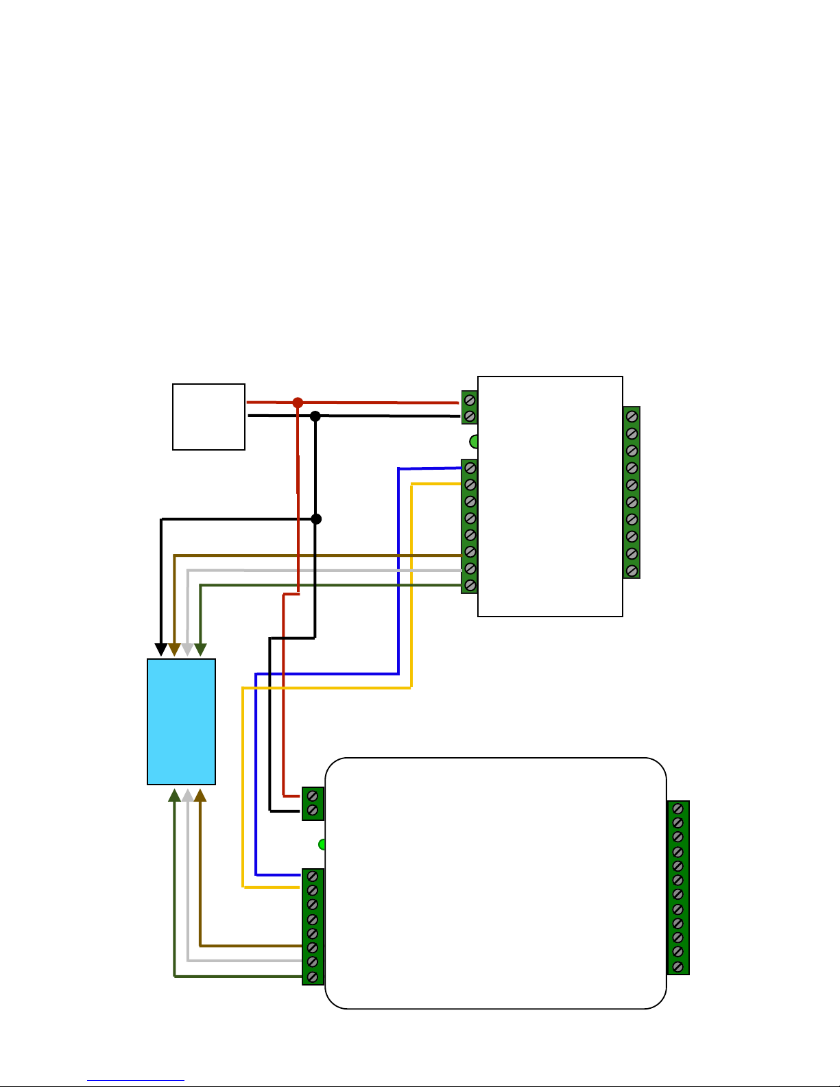
3. Field Installation Checklist
11/2/2016 Complete documentation PDFs at CypressIntegration.com
*
Board B
Access
Control
Panel
DC
Power
Supply
+8 to +16 Vdc
Ground
EXP(+)
EXP(-)
LED In!
D1/Data Out
D0/Clock Out
R1 IN
Board A
RLY4 N.O.
RLY4 Com
RLY4 N.C.
RLY3 N.O.
RLY3 Com
RLY3 N.C.
RS232 Out
RS232 In
Ground
Aux Out
Relay2 Input
Relay1 Input
485(+)
485(-)
+5 Vdc Out
Prog Res 2
Prog Res 1
LED Input
D1/Data
D0/Clock Out
8 to 16 Vdc In
Ground
Board Sizes are not to scale
☐ The Base Unit and access control panel have a common ground.
☐ The top of the Base Unit (where antenna is located) points toward the sky.
☐ For maximum range, Base Unit is installed approximately 10’ above ground (outdoors) or 5-6’ above floor
(indoors)
☐ For maximum range, there is a direct line of sight between the Handheld Reader and Base Unit
(if there is no direct line of sight, a Repeater unit is recommended).
☐ In applications with obstacles present (vehicles, trains, buildings, trees, etc.), the Base Unit is
mounted high enough to avoid interference.
☐ Metal mounting surfaces are not recommended for the Base Unit. If use of a metal surface is
unavoidable, Base Unit is spaced as far from metal surface as possible using non-metal spacer.
For additional information, see Product Manual.
Typical Handheld Reader Kit Wiring Connections
 Loading...