

Page 1
1
2 3
4
56
789
*
0#
Cancel
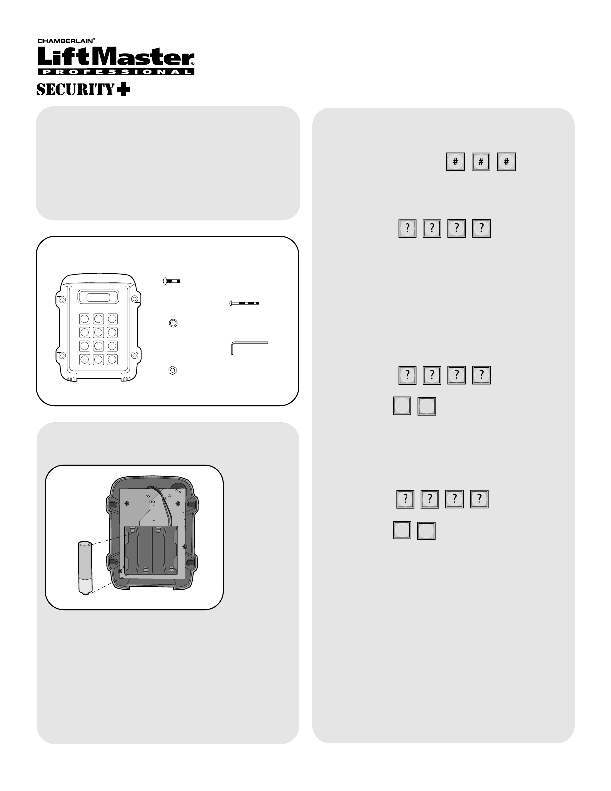
Carton Inventory
Overview
The Wireless Keypad uses a digitally secure intercom
link that allows it to control up to four access points.
The Wireless Keypad is compatible with various
Liftmaster Wireless Products.
Model WKP5LM can hold up to 5 PIN Numbers.
Model WKP250LM can hold up to 250 PIN Numbers.
Assembly
Install 4 AA Alkaline batteries (not provided). (Lithium
batteries recommended for colder environments.)
Keypad will beep.
Keypad will continuously beep indicating no Master
PIN Number has been programmed. Proceed to
Initial Setup.
1
Keypad
Models WKP5LM & WKP250LM
Wireless Keypad
Initial Setup
Step 1: On keypad press:
Step 2: Enter 4 digit Master PIN Number.
Example: 1234.
Multiple Keypads at Same Location
Step 1: On secondary Keypad enter Master PIN
Number:
Step 2: Then:
5
6
NOTE: To switch a secondary Keypad to a Main
Keypad, enter the Master PIN Number followed by
“57”.
Step 3: On Main Keypad enter Master PIN Number:
Step 4: Then:
0
5
NOTE: If a siren noise is heard the programming has
failed. Repeat process.
NOTE: This step applies only if more than one
Keypad is being used.
Bolt (4)
Washer (4)
Nut (4)
Screw (4)
Allen Wrench
®
NOTE: “ * “ is the cancel button that will cancel any
call or key sequence.
The Keypad can be used as a primary or secondary
device. Accessories should be programmed directly to
the primary device.
If programming to a GCU, see page 2.
If programming to an ULTRX900R, see page 3.
If programming to a GAPLM, see page 4.
If programming to existing receiver, see page 4.
Page 2
2
Additional GCU’s
NOTE: This step applies only if more than one GCU
is being used.
Up to four GCUs can be used. Each GCU will have to
have a different Identity. Set the Identity of the GCU
by changing the Dipswitches as shown in the chart
below. The Default Identity is 1.
GCU ID Switch #1 Switch #2
1 OFF OFF
2 ON OFF
3 OFF ON
4ON ON
Step 1: Press and hold the Learn button on the GCU
until the LED lights.
Step 2: Within 20 seconds, enter the Master PIN
Number on the main Keypad:
Followed by GCU Identity:
2
3
4
OR
OR
The Keypad will beep twice and GCU LED will blink
three times indicating programming is successful.
Repeat for additional GCU’s.
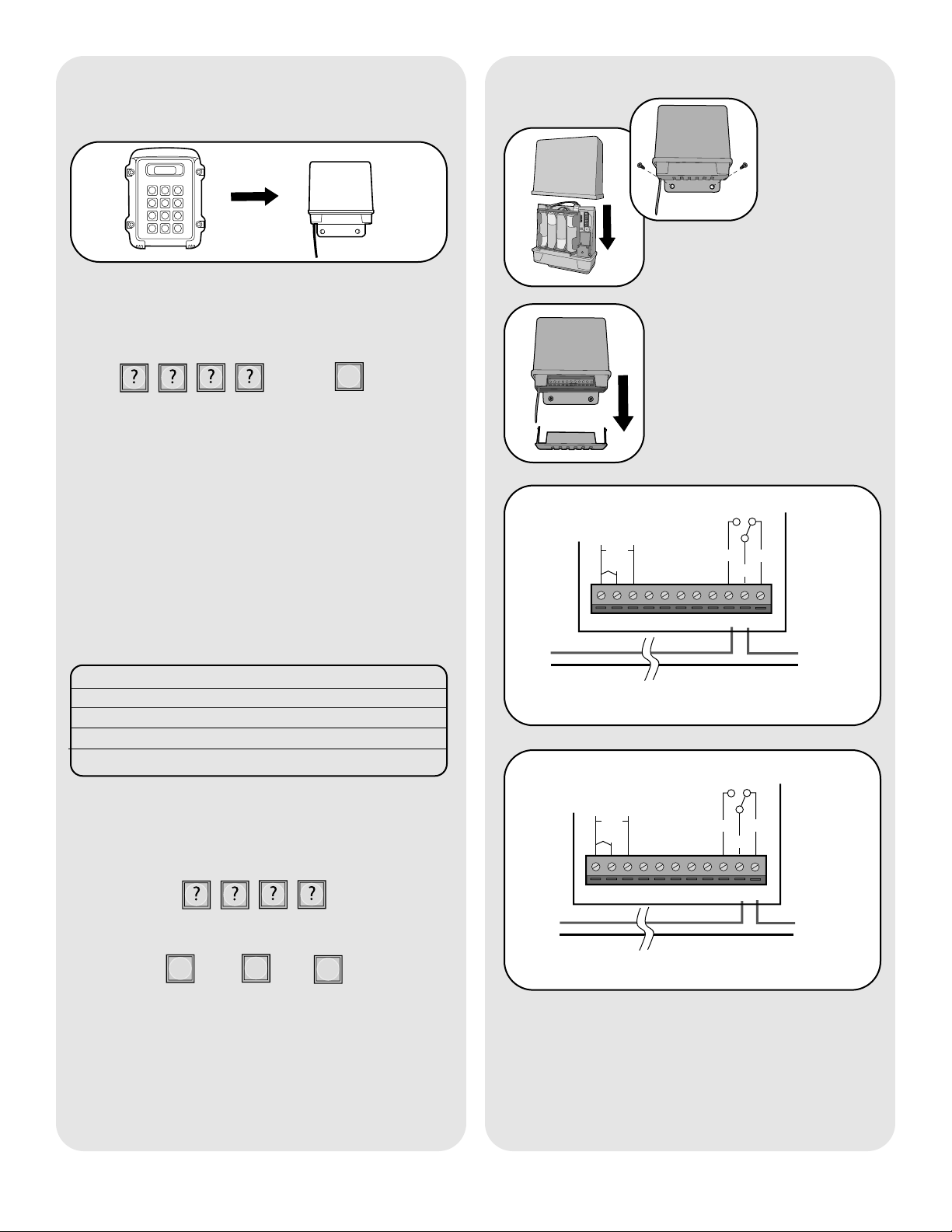
Mount GCU
Step 1: Replace GCU cover
and mount near gate operator
control box.
Step 2: Remove bottom panel
of GCU. Connect the Relay
Output of Receiver to the gate
or door. To connect to a Door
Strike or Magnetic Lock, see
diagrams below.
1
2345
67
8910
11
Proceed to Mount Keypad.
Set-Up with a Gate Control
Unit (GCU)
Step 1: Press and hold the Learn button on the GCU
until the LED lights.
Step 2: Within 20 seconds, enter the Master PIN
Number on the Main Keypad:
Then:
1
The Keypad will beep twice and GCU LED will blink
three times indicating programming is successful.
If an error tone is heard, the memory on the GCU will
need to be cleared by holding down the Learn button
until LED blinks a total of 8 times.
1
2 3
4
56
789
*
0#
Cancel
132 4567891011
DC
AC
+
-
COM
N/C
Door
Strike
Transformer/
Power Supply
Optional external power
input 10-24 Vac or DC
Door Strike- Normally Open (N/O) Connection
N/O
1324567891011
+
-
COM
N/C
Magnetic
Lock
Transformer/
Power Supply
Magnetic Lock- Normally Closed (N/C) Connection
DC
AC
Optional external power
input 10-24 Vac or DC
N/O
Page 3

3
Mount Receiver
Additional UltraRX Receivers
NOTE: This step applies only if more than one
Receiver is being used.
Up to four Receivers can be used. Each Receiver will
need a different Identity. Set the Identity of the
Receivers by changing the Dipswitches as shown in
the chart below. The Default Identity is 1.
Receiver ID Switch #2 Switch #3
1 OFF OFF
2 ON OFF
3 OFF ON
4ON ON
Step 2: Connect power to Receiver (see
ULTRX900R manual).
Step 3: Within 15 seconds, enter the Master PIN
Number on the main Keypad:
The Keypad will beep twice and Receiver Relay will
buzz indicating programming is successful.
Repeat for additional Receivers.
Followed by Receiver Identity:
2
3
4
OR
OR
Step 1: On the Receiver, place Dipswitch #1 to the
ON position.
Step 2: Connect power to Receiver (see
ULTRX900R manual).
Step 3: Within 15 seconds, enter the Master PIN
Number on the main Keypad:
Then:
1
The Keypad will beep twice and Receiver Relay will
buzz to indicate programming is successful.
If and error tone is heard, the memory on the
Receiver will need to be cleared by holding down the
Learn button until LED starts to flash.
Set-Up with UltraRX Extreme
Range Receiver (ULTRX900R)
Step 1: Mount the Receiver
with the Terminal Block at the
bottom and the antenna
hanging straight down.
NOTE: Metal surfaces can
shorten the range of the
Receivers. If mounting on a
metal surface and long range is
required, use a non-metallic
spacer to move the Receiver
away from the metal surface.
Step 2: Connect the Relay Output of Receiver to the
gate or door. To connect to a Door Strike or Magnetic
Lock, see diagrams below.
1 2 3 4 5 6 7 8 9 10 11 12 13
132 4567891011
+
-
N/O
COM
N/C
Door
Strike
Transformer/
Power Supply
Open/
Close
12 13
Door Strike- Normally Open (N/O) Connection
DC
AC
Optional external power
input 10-24 Vac or DC
132 4 5 6 7 8 9 10 11
+
-
Magnetic
Lock
Transformer/
Power Supply
12 13
Magnetic Lock- Normally Closed (N/C) Connection
DC
AC
Optional external power
input 10-24 Vac or DC
N/O
COM
N/C
Open/
Close
Proceed to Mount Keypad.
1
2 3
4
56
789
*
0#
Cancel
Step 1: On the Receiver, place Dipswitch #1 to the
ON position.
Page 4
4
Set-Up with Existing Network
Gate Access Panel (GAPLM) as Primary
Access Control Unit
Enter Master PIN Number on Keypad:
5
6
Enter Master PIN Number on GAPLM:
Then:
Then:
“BEEP” “BEEP”
Door Access Intercom (DAILM) as
Primary Access Control Unit
Enter Master PIN Number on Keypad:
5
6
Press and release the Learn button on the DAILM.
Keypad will beep twice indicating programming is
successful.
Then:
Keypad as Primary Access Control Unit
Step 1: On Secondary Keypad enter Master PIN
Number:
Step 2: Then:
5
6
NOTE: To switch a Secondary Keypad to a Main
Keypad, enter the Master PIN Number followed by
“57”.
Step 3: On Main Keypad enter Master PIN Number:
Step 4: Then:
0
5
NOTE: If a siren noise is heard the programming has
failed. Repeat process.
Programming Secondary Keypads to
additional Receivers (GCU or
ULTRX900R)
A Secondary Keypad defaults to activating
Receiver #2 when a PIN Number is entered on that
Keypad.
To activate Receiver #3:
Enter Master PIN Number on Keypad:
5
8
Then:
To activate Receiver #4:
Enter Master PIN Number on Keypad:
5
9
Then:
0
5
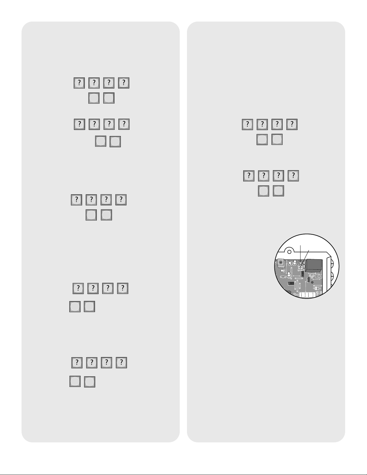
Pre-Installed Liftmaster
Receiver
Step 1: Pry open the front
panel of the receiver case
with a coin or a screwdriver.
Step 2: Press and release
the Learn button on the
receiver. The Indicator Light will
light for 30 seconds indicating that
receiver is in Learn Mode.
Step 3: Within 30 seconds enter Master PIN Number
on Keypad.
Step 4: Press “1”.
Repeat Steps 2-4 for each remote, or control device
that will be used to access the Liftmaster door or gate
operator.
Program
Erase All Control Codes
Press and hold the Learn button on the receiver until
the Indicator Light turns off indicating that the receiver
memory is clear (about 6 seconds).
12V
HIGH
NORM
C
P2
M
Indicator Light
Learn Button
Page 5

5
Operation
Enter existing Master PIN Number on Keypad:
0
9
Enter new Master PIN Number:
Change Master PIN Number
“BEEP”
“BEEP”
A temporary PIN Number can be used only once
within a 24 hour period.
NOTE: The WKP5LM can hold up to 5 Temporary
PIN Numbers while the WKP250LM can hold 15.
Enter Master PIN Number on Keypad:
5
1
Enter temporary PIN Number:
If the temporary PIN Number applies only to a certain
Receiver, enter the PIN Number followed by the
Receiver Identity (1-4). The result will be a five digit
PIN Number (example: 12341).
Temporary PIN Numbers
“BEEP”
“BEEP”
The WKP5LM can support up to 5 PIN Numbers
while the WKP250LM can support 250.
Enter Master PIN Number on Keypad:
9
Enter new PIN Number:
Adding PIN Numbers
“BEEP”
“BEEP”
Enter Master PIN Number on Keypad:
7
Enter PIN number you want to remove:
A triple beep indicates a PIN Number has been
entered that does not exist. The Master PIN Number
cannot be deleted.
Erasing PIN Numbers
“BEEP”
“BEEP” “BEEP”
To use Keypad, enter any valid PIN Number. With
multiple Receivers, enter the PIN Number followed by
the Receiver Identity (1-4).
Mount Keypad
Step 1
Choose mounting location for Keypad. Remove the
back panel and attach it to a solid surface or post.
Mount the Keypad onto the back panel with screws.
Tighten screws with Allen wrench.
Step 2
It is recommended that Keypad be mounted to a
Gooseneck post or non-metallic surface. If it is
necessary to mount Keypad to a metal surface, use a
non-metallic spacer to move the Keypad away from
the metal surface.
Page 6

© 2007, The Chamberlain Group Inc.
114A3531 All Rights Reserved
NOTICE: To comply with FCC and or Industry Canada rules (IC), adjustment or modifications of this receiver and/or transmitter are prohibited,
except for changing the code setting or replacing the battery. THERE ARE NO OTHER USER SERVICEABLE PARTS.
Tested to Comply with FCC Standards FOR HOME OR OFFICE USE. Operation is subject to the following two conditions: (1) this device may not
cause harmful interference, and (2) this device must accept any interference received, including interference that may cause undesired operation.
FOR TECHNICAL SUPPORT DIAL OUR TOLL FREE NUMBER:
1-800-528-2806
www.liftmaster.com
To keep gate open during a party or activity so the gate
will not have to open with each guest, the Keypad can
be programmed to remain open until it is cycled close.
When the Keypad is in Party Mode the GCU or
ULTRX900R MUST be connected to an external
+12 Volt power supply.
Enter Master PIN Number on Keypad:
5
4
To close gate and exit Party Mode, cycle the gate by
entering a PIN Number or by pressing the button on a
remote or intercom.
Party Mode
The Keypad can be set to one of three channels to
prevent range-reducing interference from conflicting
radio transmitters. Any accessories programmed to the
Receiver will have to have memory cleared and be
reprogrammed.
Enter Master PIN Number on Keypad:
5
5
Enter one of the following channels:
1
2
3
OR
OR
Alternate Channel Selections
“BEEP”
Default setting is Channel 2.
When it is dark, the panel will light when it detects
movement (up to 5') or when a button is pressed.
Enter Master PIN Number on Keypad:
0
8
1
2
3
OR
OR
Enter one of the following brightness levels:
Default setting is 2.
Keypad Brightness
“BEEP”
The AA batteries (not provided) in the Keypad will
typically last up to 3 years depending on use. (Lithium
batteries recommended for colder environments.)
Battery
 Loading...