

Page 1

WDG-5912
Spec Sheet
Programmable USB Wedge
Page 1 of 2
WDG-5912SS
Page 2

Electrical and Mechanical Specifications
Product Specifications
The WDG-5912 Wedge is a compact and durable device which automatically adds badge data to IBM
and compatible PC systems, Tektronix systems, MAC OS X, as well as most popular POS terminals.
The Wedge enhances productivity in a wide variety of retail, security , and Time & Attendance
applications by converting badge, wand, or scanner information to the appropriate keystrokes. Input
can be Wiegand, Strobed ABA, or RS232 Serial data.
The WDG-5912 parameters are programmable through a serial connection to a VT-100 terminal or
equivalent (configured for 9600 baud 8,1,N). Trailers, headers, and badge number processing are
configurable through the programming interface. Refer to the WDG-5912 programming manual for
detailed programming instructions. The WDG-5912 will work with most host computers that support a
USB keyboard interface.
Supply Voltage: 5 Vdc from USB Interface
Supply Current: 100mA
Readers requiring 100mA or greater current
or greater than 5 VDC will require an
external supply
Physical Dimensions: 4.25” x 1.125” excluding
connectors.
For indoor use only
This complies with part 15 of the FCC rules
Operation is subject to the following two conditions:
(1) This device may not cause harmful interference, and
Page 2 of 2
Cypress Computer Systems 1778 Imlay City Rd Lapeer, MI 48446
ZZZ.&\SUHVV&RPSXWHU.FRP
Solutions@CYPRX.com Copyright @201
Page 3
©2005 Cypress Computer Systems, Inc. 9/20/05 WDG-5912 Connection Diagram V1.00 1
CYPRESS
WDG-5912
Adds Automatic Data Entry to Computers and Terminals
Connection Diagram
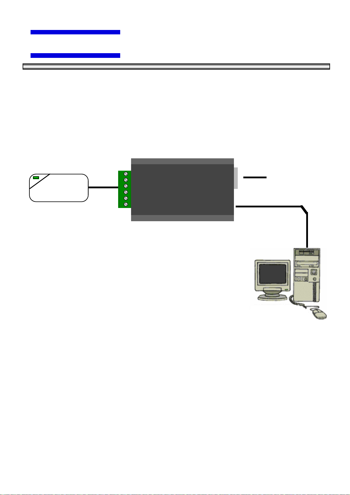
Product Description
The WDG-5912 Wedge is a compact and durable device which automatically adds badge data to IBM
and compatible PC systems, Tektronix systems, MAC OS X, as well as most popular POS terminals.
The Wedge enhances productivity in a wide variety of retail, security , and Time & Attendance
applications by converting badge, wand, or scanner information to the appropriate keystrokes. Input
can be Wiegand, Strobed ABA, or RS232 Serial data.
WDG-5912
The WDG-5912 parameters are programmable through a serial connection to a VT-100 terminal or
equivalent (configured for 9600 baud 8,1,N). Trailers, headers, and badge number processing are
configurable through the programming interface. Refer to the WDG-5912 programming manual for
detailed programming instructions. The WDG-5912 will work with most host computers that support a
USB keyboard interface.
Reader
(Wiegand, MagStripe,
BarCode,Proximity)
Terminal or Computer
Cypress Computer Systems, Inc. • 1778 Imlay City Rd. • Lapeer, MI 48446-3206
TX(810)245-2300 • FX(810)245-2332 • www.cypresscom.com
General
RS-232 Interface and
Programming Port
USB Interface
Programmable USB Wedge
Page 4
©2005 Cypress Computer Systems, Inc. 9/20/05 WDG-5912 Connection Diagram V1.00 2
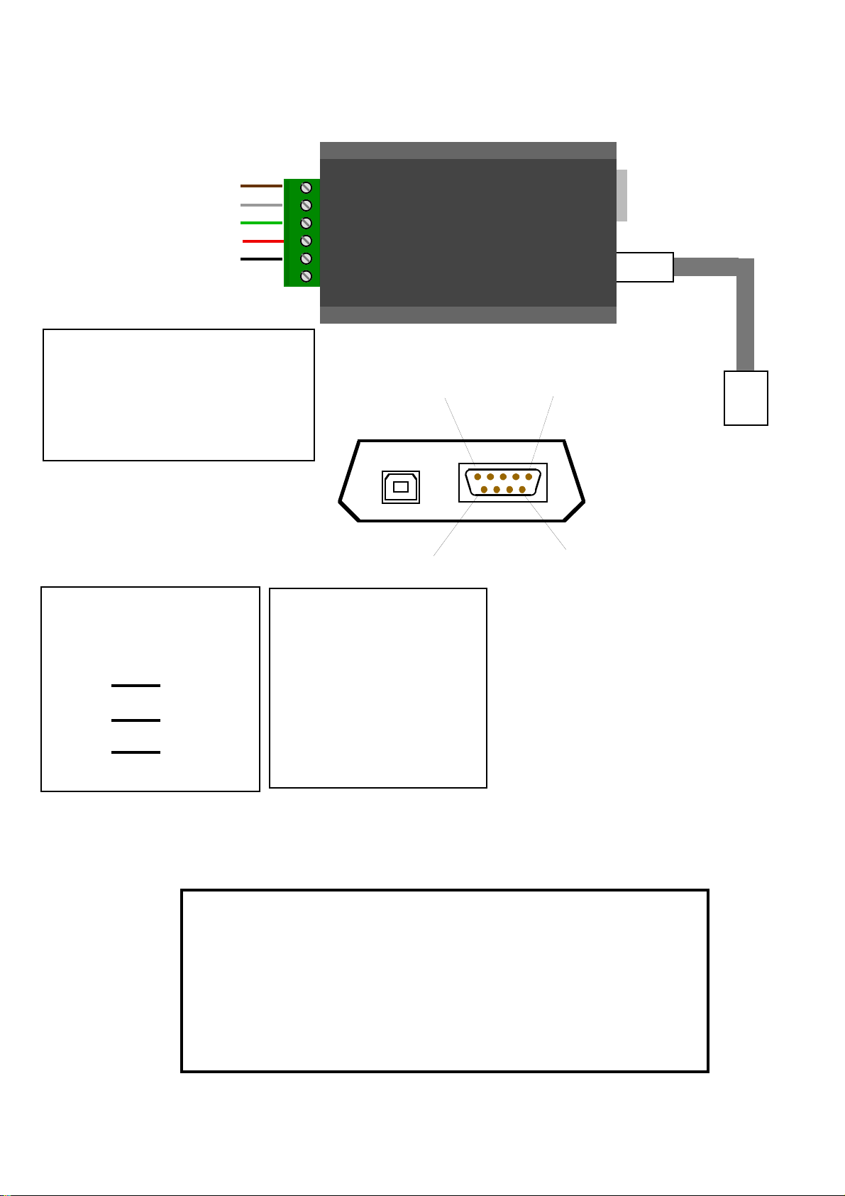
Standard WDG-5912 Connections
This device complies with part 15 of the FCC Rules.
Operation is subject to the following two conditions:
(1) This device may not cause harmful interference, and
(2) this device must accept any interference received,
including interference that may cause undesired operation.
STATEMENT OF COMPLIANCE
Data 0 / Strobe(Green)
Data 1 / Data (White)
LED (Brown)
+5 Vdc Out (Red)
GND (Black)
CYPRES
S
To Computer USB
port or USB Hub
Supply Voltage: 5 Vdc from USB Interface
Supply Current: 100mA
Readers requiring 100mA or greater current
or greater than 5 VDC will require an
external supply.
WDG-5912
N/C
USB Cable
USB “B”
DB-9 Male
DB-9 Connections
2 RXD (Data In)
3 TXD (Data Out)
5 GND
9 + 5VDC Out
USB “B”
DB-9 Male
156
9
The RS-232 port is set
for 9600 Baud, 8,N,1.
All printable ASCII data
received from the port will
be sent to the USB keyboard
output.
The RS-232 port also
provides the programming
interface for the wedge.
Refer to programming manual
for details.
DB-9 Connections to
standard PC Com Port
Wedge
Computer
DB9-2
DB9-5
DB9-5
DB9-3
DB9-3
DB9-2
Page 5

©2005 Cypress Computer Systems, Inc. 9/20/05 WDG-5912 Connection Diagram V1.00 3
WDG-5912 Dimensions
Top View
Side View
4.25”
2.625”
1.125”
(10.8 cm)
(2.86 cm)
(6.67 cm)
Page 6
©2005 Cypress Computer Systems, Inc. 9/20/05 WDG-5912 Connection Diagram V1.00 4
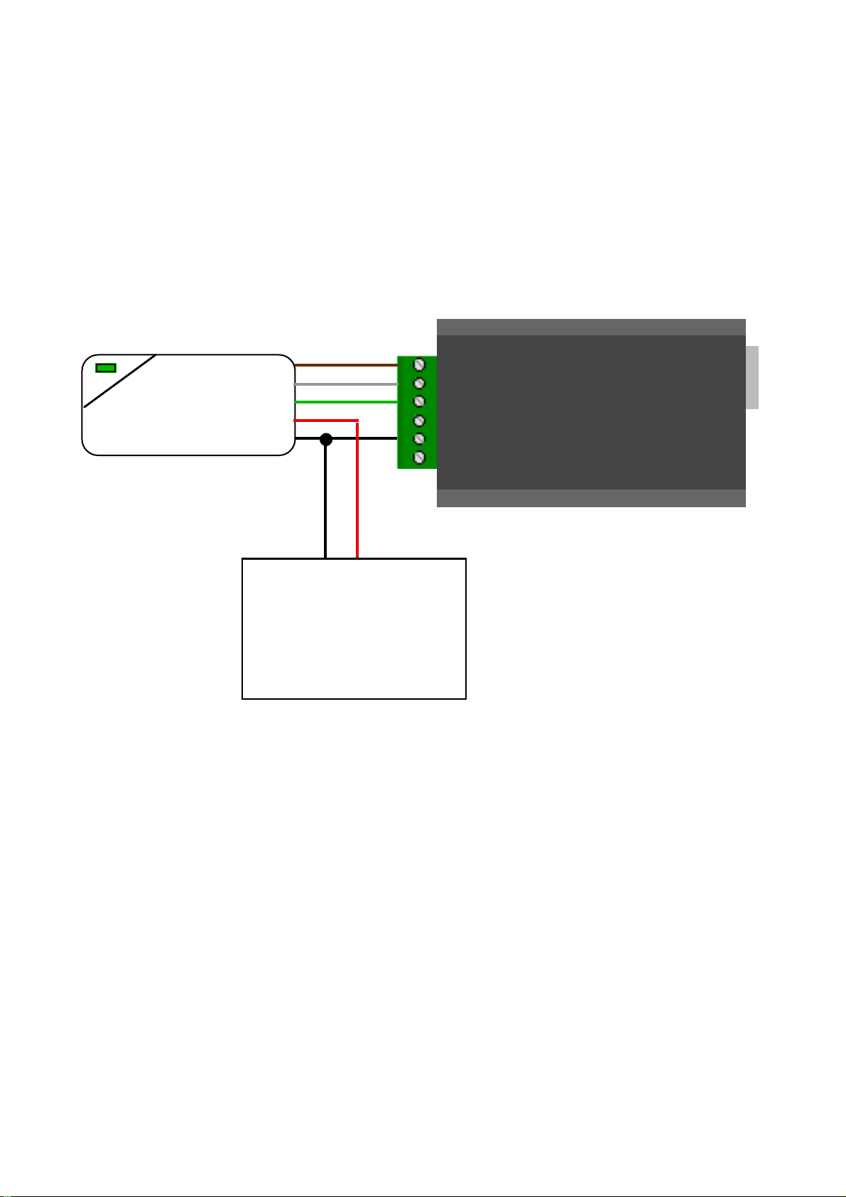
WDG-5912 External Supply for Reader
Reader Power Supply
Ground is connected to
Reader and Wedge.
Power (+VDC) is connected
to reader ONLY.
External power should not
be applied to +5 VDC
connection of wedge.
(+)
(-)
An external power supply may be required for applications where the
combined current requirements of the wedge and reader exceed the
capacity of the USB interface. A power supply will also be required
for readers that specify more than 5 volts supply voltage (ie 12VDC )
Page 7

©2010 Cypress Computer Systems, Inc. 2/1/10 WDG-5912 Programming Instructions Version 1.0.2 Page 1
CYPRESS
WDG-5912 Programming Instructions
Cypress WDG-5912 USB Programmable Wedge
Page 8

©2010 Cypress Computer Systems, Inc. 2/1/10 WDG-5912 Programming Instructions Version 1.0.2 Page 2
WDG-5912 Programming - Getting Started
A programming interface is provided for the WDG-5912 through the RS-232 port. Programming
There are some important differences between the 4612 series and 5912 procedures.
Required equipment to program the WDG-5912:
1. RS-232 cable F-F Crossover type.
2. Terminal program (such as Hyperterminal) running VT-100 emulation at 9600 baud, 8, N, 1 with
Echo ON, no hardware handshaking.
3. RS-232 port on host computer running the terminal program.
Placing the Wedge into programming mode:
The WDG-5912 in normal operation will pass all printable ASCII characters input to the serial port to
the USB keyboard output. To utilize the RS-232 port for programming purposes it is necessary to
place the port / wedge into programming mode.
The wedge should be connected to the computer through the USB cable to provide power. The
RS-232 cable should be installed and the terminal program running.
Type the characters + + + into the terminal program.
The wedge should answer with “Command mode”.
Now the standard Cypress programing commands can be used i.e. \R \L etc. If you have not used
the Cypress programming interface, this manual will cover the details in the following pages.
After programming is complete, the wedge can be placed back into normal operation by pressing
the “Esc” (Escape) key.
Note: If you are using the same computer to program and host the USB interface, a condition can
occur during programming where a keepers will enter an infinite loop. This can happen when; the
terminal program is the active window, the wedge is in normal mode, and a key other than + is
pressed. The wedge will output the character to the terminal window where it will be fed back to the
wedge through the RS-232 port where it will then be output as a keystroke.
To terminate this condition, briefly unplug the RS-232 connection to the wedge.
Page 9
©2010 Cypress Computer Systems, Inc. 2/1/10 WDG-5912 Programming Instructions Version 1.0.2 Page 3
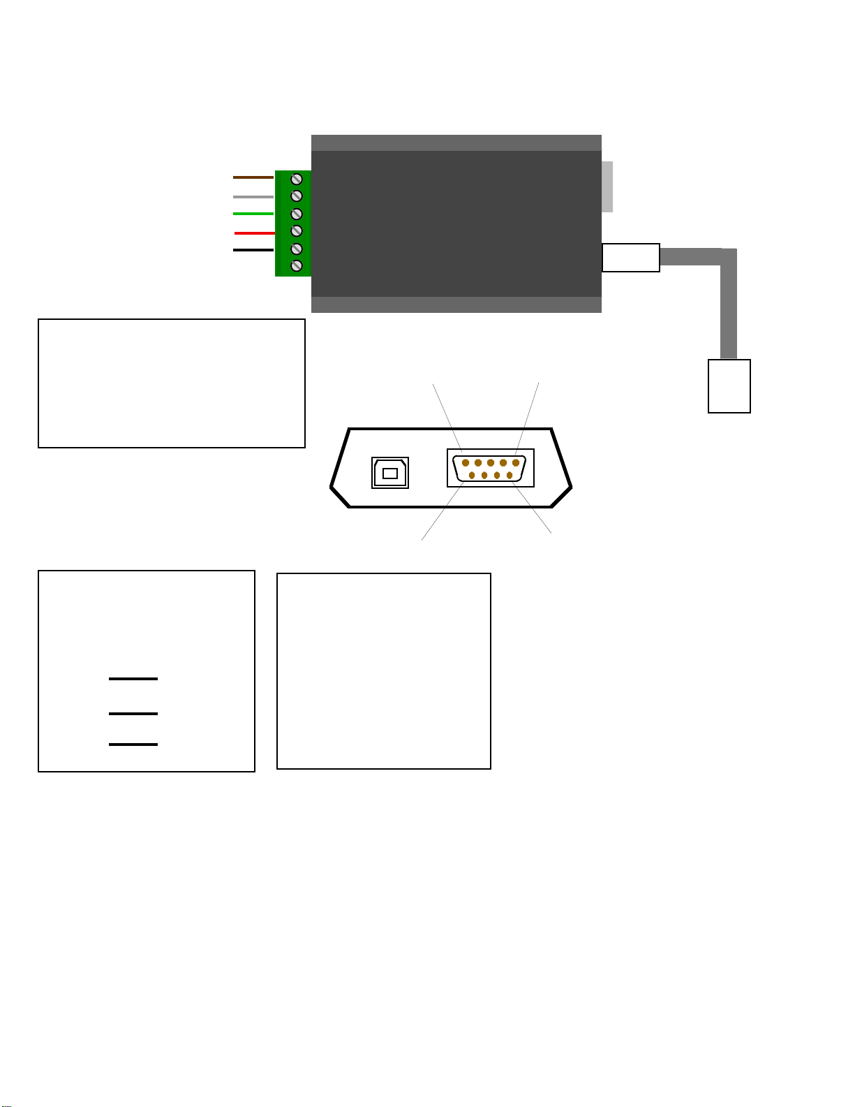
Standard WDG-5912 Connections
Data 0 / Strobe(Green)
Data 1 / Data (White)
LED (Brown)
+5 Vdc Out (Red)
GND (Black)
CYPRESS
To Computer USB
port or USB Hub
Supply Voltage: 5 Vdc from USB Interface
Supply Current: 100mA
Readers requiring 100mA or greater current
or greater than 5 VDC will require an
external supply.
WDG-5912
N/C
USB Cable
USB “B”
DB-9 Male
DB-9 Connections
2 RXD (Data In)
3 TXD (Data Out)
5 GND
9 + 5VDC Out
USB “B”
DB-9 Male
156
9
The RS-232 port is set
for 9600 Baud, 8,N,1.
All printable ASCII data
received from the port will
be sent to the USB keyboard
output.
The RS-232 port also
provides the programming
interface for the wedge.
Refer to programming manual
for details.
DB-9 Connections to
standard PC Com Port
(Programming Cable)
Wedge
Computer
DB9-2
DB9-5
DB9-5
DB9-3
DB9-3
DB9-2
Page 10

©2010 Cypress Computer Systems, Inc. 2/1/10 WDG-5912 Programming Instructions Version 1.0.2 Page 4
Basic Command Structure:
All commands start with a Backslash “\” and are upper case only
\P - Load Simulator Template
\P@ = defaults
\PH = Badge Peeler {hexadecimal output}
\Q - Load Reader Template
\Q@ = defaults
\QH = Badge Peeler {No Processing of Formats}
\R - Show Reader Parameters
\S - Show Simulator Parameters
\L - Burn specified NVRAM locations
\P [template code]
\P@ - load default Simulator Parameters
\PA - load profile A
...
\PZ - load profile Z
\Q [template code]
\Q@ - load default Reader Parameters
\QA - load profile A
...
\QZ - load profile Z
\L [number of bytes to burn] [Starting address] [Hex codes...]
\L01075FF - programs $FF into location $075
\L060C508FF08200100 - programs 6 bytes starting at location $0C5: 08 FF 08 20 01 00
>>
When youʼve typed the nth byte, youʼll get the “>>” prompt.
WDG-5912 Programming - The Programming Interface
Page 11

©2010 Cypress Computer Systems, Inc. 2/1/10 WDG-5912 Programming Instructions Version 1.0.2 Page 5
Step by Step - Using the Wedge for custom Wiegand formats
This section will explain how to use the Cypress programmable wedge to generate
Facility Code and Badge numbers from Wiegand data streams of 24 to 64 bits.
The user should be familiar with Decimal, Hexadecimal and Binary number systems and a reader
should reconnected to the wedge and be operational. condition.
The user will also need to know any formatting details of the decoded data.
Different processes are required for Strobed/ABA or Wiegand/ABA data. These procedures apply to
Wiegand/Binary data only.
There are several steps involved in getting the desired facility code and badge numbers from
Wiegand data using the Cypress Wedge.
These are:
1. Determine the number of bits in the raw Wiegand data.
2. Determine the actual data bits (raw data) from the Wiegand card reader.
3. Determine where the desired facility code is located in the raw data.
4. Determine where the desired badge data is located in the raw data.
5. Composing programming strings to filter the facility code and badge data from
the incoming raw Wiegand data.
6. Determine the number of decimal digits for the facility code and badge data.
7. Composing programming strings to correctly display the decimal facility code and badge
numbers.
We will go through each step with the “Standard” 26 bit Wiegand badge as an example:
First, determine the number of bits in the data stream and the raw data coming from the reader/badge.
Place the Wedge into “Badge Peeler” mode by entering \PH and \QH into the programming interface.
This will cause the wedge to generate an output that displays the number of bits and the badge data in
raw hexadecimal format.
Lets say our 26 bit badge yielded the output “ 26=000002F62712” from the badge peeler
mode. We now know it is 26 bits (the numbers before “=”) and we have the raw binary data in
hexadecimal form.
We will use the worksheet provided at the end of this document to work out the bit positions and
conversion information. The worksheet can be printed and used with pen and pencil for calculating the
programming strings.
Reset the programming parameters back to factory defaults using the reset jumper block before
proceeding.
Page 12
©2010 Cypress Computer Systems, Inc. 2/1/10 WDG-5912 Programming Instructions Version 1.0.2 Page 6
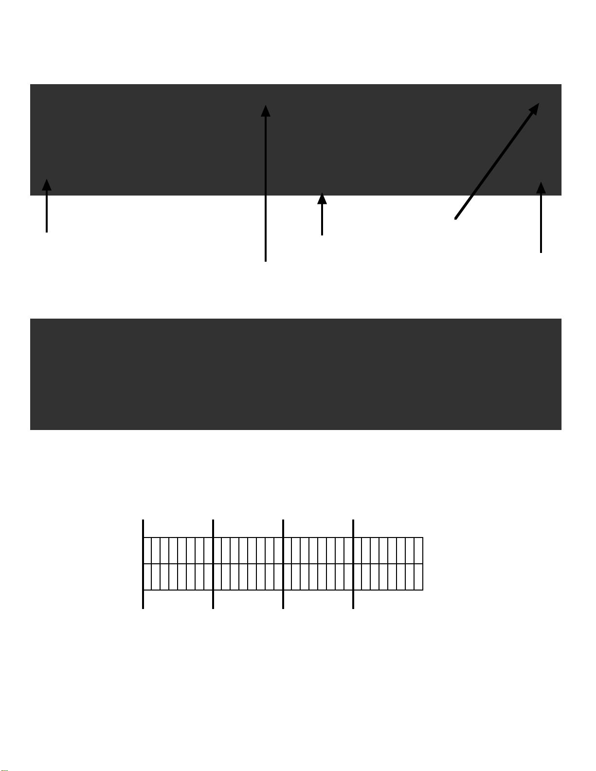
This worksheet grid represents the internal 8 byte buffer of the Cypress Programmable Wedge
Most Significant Bit 0x01
Least Significant Bit 0x40
Byte number
Bit Number (Decimal)
from LSb to MSb
Each Hex digit is converted to its binary equivalent and filled into the bit boxes.
We added a zero above the most significant byte for clarity.
The bits are processed Right Justified.
21726F2
First write the individual Hexadecimal digits over each 4 bit group (2 per byte) starting from Right to left. The
upper most significant bits/bytes are zero padded.
456
123456789
101112131415161718192021222324252627282930313273F
3E3D3C3B3A
393837363534333231302F
2E2D2C2B2A
292827262524232221
40
21726F2
0
0101000011100010011110110100000
0
BIT count
Step by Step - Using the Wedge for custom Wiegand formats
Page 13

©2010 Cypress Computer Systems, Inc. 2/1/10 WDG-5912 Programming Instructions Version 1.0.2 Page 7
456
123456789
101112131415161718192021222324252627282930313273F
3E3D3C3B3A
393837363534333231302F
2E2D2C2B2A
292827262524232221
40
21726F2
0
0101000011100010011110110100000
0
Since we know what a “standard 26 bit” format is, we can define the bit functions and their
positions:
P = Parity Bit
F = Facility Code bit
B = Badge number bit
PBBBBBBBBBBBBBBBFFFFFFFFP
Assuming we know the badge format, we can define bit functions by location.
If you do not know the badge format, then you will have to find the bit pattern in the raw
stream that represents the desired facility code and/or badge number.
The best way to find an expected number is to take the decimal badge number or facility
code and convert it to hexadecimal. Then look for the binary bit pattern in the raw data
represented by the hexadecimal number.
456
123456789
101112131415161718192021222324252627282930313273F
3E3D3C3B3A
393837363534333231302F
2E2D2C2B2A
292827262524232221
40
21726F2
0
01010000111000100111101101000000PBBBBBBBBBBBBBBBFFFFFFF
Now we can gather parameters that will be entered into the wedge programming interface.
Notice that these locations will filter out the parity bits.
PFB
The facility code bits
start at 0x28 and are
8 bits long
The badge bits
start at 0x30 and are
16 (0x10) bits long
Step by Step - Using the Wedge for custom Wiegand formats
Page 14

©2010 Cypress Computer Systems, Inc. 2/1/10 WDG-5912 Programming Instructions Version 1.0.2 Page 8
The Wiegand preprocessor string for Wiegand Preprocessor 0 (WPP0) would be:
\L050C50828083010
Broken down to each parameter:
\L ; Programming string prefix
05 ; There are 5 bytes of data in the programming string
0C5 ; The address in the programming parameter map of WPP0
08 ; Defines 8 byte (64 bit buffer) to hold data
28 ; Start of facility code bits in 64 bit buffer (0x28)
08 ; Defines 8 bit length of facility code data
30 ; Start of badge number data in 64 bit buffer (0x30)
10 ; Defines 16 bit length of badge data (0x10)
075
24 25 26 27 28 29 30 31 32 33 34 35 36 37 38 39 40 41 42 43 44
00 00 01 00 00 00 00 00 00 00 00 01 00 00 00 00 00 00 00 00 00
45 46 47 48 49 50 51 52 53 54 55 56 57 58 59 60 61 62 63 64
00 00 00 00 00 00 00 00 00 00 00 00 00 00 00 00 00 00 00 00
65 66 67 68 69 70 71 72 73 74 75 76 77 78 79 80 81 82 83 84
00 00 00 00 00 00 00 00 00 00 00 00 00 00 00 00 00 00 00 00
85 86 87 88 89 90 91 92 93 94 95 96 97 98 99 100 101 102 103
00 00 00 00 00 00 00 00 00 00 00 00 00 00 00 00 00 00 00 00
Wiegand Binary Format Table - Wedge programming interface
Now we need to tell the Wiegand Preprocessor (WPP0) to process 26 bit streams using the
above criteria.
The number in the upper left corner is 0x75, a hexadecimal number that gives the
starting address of the Format Table. The 24 bit format would start at 0x75.
For example, a 32 bit format would be located at 0x7D
The 26 bit format we are interested in is located at 0x77.
Now that we know the address of the 26 bit format, we will place a 0x02 in that location.
The 0x02 tells the Wedge to use Wiegand Preprocessor #0 (WPP0)
See next page for details on the programming string to set 0x02 at location 0x77
Step by Step - Using the Wedge for custom Wiegand
Page 15

©2010 Cypress Computer Systems, Inc. 2/1/10 WDG-5912 Programming Instructions Version 1.0.2 Page 9
The programming string to tell the wedge “Use WPP0 on 26 bit formats would be:
\L0107D02
Broken down to each parameter:
\L ; Programming string prefix
01 ; There are 1 bytes of data in the programming string
077 ; The address of the programmed parameter (26 bit)
02 ; Parameter that defines use of Wiegand Preprocessor 0 (WPP0)
Lets assume we want the Facility Code to output as a 3 digit decimal number.
Upper digits will be zero padded from left to right.
The programming string to tell the wedge to use a 3 digit decimal number for the Facility Code:
\L0105B03
Broken down to each parameter:
\L ; Programming string prefix
01 ; There are 1 bytes of data in the programming string
05B ; The address of the programmed parameter
03 ; The number of digits to use in the Facility field. (This can be set to zero if no Facility needed)
Lets assume we want the Badge Number to output as a 5 digit decimal number.
Upper digits will be zero padded from left to right.
The programming string to tell the wedge to use a 5 digit decimal number as the Badge:
\L0105D05
Broken down to each parameter:
\L ; Programming string prefix
01 ; There are 1 bytes of data in the programming string
05D ; The address of the programmed parameter
05 ; The number of digits to use in the badge Field
Step by Step - Using the Wedge for custom Wiegand
Page 16

©2010 Cypress Computer Systems, Inc. 2/1/10 WDG-5912 Programming Instructions Version 1.0.2 Page 10
\L050C50828083010
\L0107D02
\L0105B03
\L0105D05
If the four strings are entered through the programming interface:
Then our output from the raw data in our example would be:
12305001
Step by Step - Using the Wedge for custom Wiegand
Page 17

©2010 Cypress Computer Systems, Inc. 2/1/10 WDG-5912 Programming Instructions Version 1.0.2 Page 11
\R
======== Reader Parameters =======
073 Interface: 00
074 Format: 00
075
24 25 26 27 28 29 30 31 32 33 34 35 36 37 38 39 40 41 42 43 44
00 00 01 00 00 00 00 00 00 00 00 01 00 00 00 00 00 00 00 00 00
45 46 47 48 49 50 51 52 53 54 55 56 57 58 59 60 61 62 63 64
00 00 00 00 00 00 00 00 00 00 00 00 00 00 00 00 00 00 00 00
65 66 67 68 69 70 71 72 73 74 75 76 77 78 79 80 81 82 83 84
00 00 00 00 00 00 00 00 00 00 00 00 00 00 00 00 00 00 00 00
85 86 87 88 89 90 91 92 93 94 95 96 97 98 99 100 101 102 103
00 00 00 00 00 00 00 00 00 00 00 00 00 00 00 00 00 00 00 00
0C5 User 0 WPP: 000000000000
0CB + Offset 0: 0000 0CD - Offset 0: 0000
0DC User 1 WPP: 0000000000
0E1 Odd Mask 1: 000000000000000000 0EA Even Mask 1:000000000000000000
0F3 ABA Clock Polarity: 00
0F4 ABA PAN (Strt,Num): 00,00
0F6 ABA XAN (Strt,Num): 00,00
073 Interface: 00
074 Format: 00
073 is the address of the Interface Parameter. It indicates the
type of reader connected to the wedge.
00 = Wiegand, 01= Strobed.
The Format Parameter is also used to specify the type of
reader. 00 = Binary, 01 = ABA encoding
To change the Interface and format parameters, use the following examples:
\L0107300 - Wiegand Interface
\L0107301 - Strobed Interface
\L0107400 - Binary Formats (24 to 103 bits)
\L0107401 - ABA Formats
Since the 2 fields are sequential in memory, the following example shows both
parameters being set with one command string:
\L020730001 - Wiegand Interface with ABA Encoding
Commands
A similar screen will appear when connected to a VT-220
type terminal
WDG-5912 Programming - The Reader interface Screen
Page 18

©2010 Cypress Computer Systems, Inc. 2/1/10 WDG-5912 Programming Instructions Version 1.0.2 Page 12
075
24 25 26 27 28 29 30 31 32 33 34 35 36 37 38 39 40 41 42 43 44
00 00 01 00 00 00 00 00 00 00 00 01 00 00 00 00 00 00 00 00 00
45 46 47 48 49 50 51 52 53 54 55 56 57 58 59 60 61 62 63 64
00 00 00 00 00 00 00 00 00 00 00 00 00 00 00 00 00 00 00 00
65 66 67 68 69 70 71 72 73 74 75 76 77 78 79 80 81 82 83 84
00 00 00 00 00 00 00 00 00 00 00 00 00 00 00 00 00 00 00 00
85 86 87 88 89 90 91 92 93 94 95 96 97 98 99 100 101 102 103
00 00 00 00 00 00 00 00 00 00 00 00 00 00 00 00 00 00 00 00
Wiegand Binary Format Table
Starting at address 075, the table indicates which process is to be applied to the various
number of bits that could be encountered.
00 = default
01 = standard
02 = User defined WPP 0
03 = User defined WPP 1
FF = ignore
To change the process byte for 32 bits, use the following command string:
\L0107D02 - change to “User Defined WPP 0”
{remember, you are counting in HEX not decimal}
WPP = Wiegand Pre Processor
0D FF 08 15 54
Default Process:
08 28 08 30 10
Standard Process:
13 bytes in buffer
field 1 = num of bits read
Badge Field starts 21 bits
84 bits in badge field
8 bytes in buffer (64 bits)
Start of Facility Code Field (40 bits)
16 bits in badge field
8 bits in FC field
Start of Badge Field (48 bits)
FF - Field 1 contains the number of
bits read instead of the contents of
the buffer at a specified location.
Therefore, the 3rd byte (08) is
ignored.
You would use this to process a
standard 26 bit Wiegand Format
The default process is useful for “dumping”
all the information in a Wiegand badge.
Parity Bits, fixed codes, site code, badge
number, etc. By using the FF code as
shown, the number of bits will be
accumulated for later output by the simulator.
WDG-5912 Programming - The Reader interface Screen
Page 19

©2010 Cypress Computer Systems, Inc. 2/1/10 WDG-5912 Programming Instructions Version 1.0.2 Page 13
0C5 User 0 WPP: 0000000000
This is a little complicated but definable. The WPP tells the Reader Interface how
to process the incoming bit stream. Number of bytes needed to buffer the read,
how far into the buffer the Facility Code field is, number of bits in the Facility Code,
starting position of the Badge Field, how many bits.
Example User Process:
08 24 0A 2E 12
1 2 3
012345678901234567890123456789012345
e011010FFFFFFFFFFCCCCCCCCCCCCCCCCCCo
Letʼs take a typical coding form and create a User Defined WPP.
36 bit custom format
some fixed bits at 1,2,3,4,5 &, 6
Facility Code = 10 bits
Start Position = 7
Card Number = 18 bits
Start Position 17
1 2 3 4 5 6
0123456789012345678901234567890123456789012345678901234567890123
e011010FFFFFFFFFFCCCCCCCCCCCCCCCCCCo
123456789ABCDEF0123456789ABCDEF0123456789ABCDEF0123456789ABCDEF0
1 2 3 4
Pick a buffer size that will hold the
entire read (64,88, or 103)
64 bit Buffer
(8 bytes)
10 bits in
Facility Code
Field
18 bits in
Card
Number
Field
To force the 36 bit format to be processed using the WPP, set the process code to 2.
\L0108102
type \R to confirm programming
WDG-5912 Programming - Details of the Wiegand PreProcessor
Page 20

©2010 Cypress Computer Systems, Inc. 2/1/10 WDG-5912 Programming Instructions Version 1.0.2 Page 14
1 2 3 4 5 6 7 7
01234567890123456789012345678901234567890123456789012345678901234567890123456789
e011010FFFFFFFFFFCCCCCCCCCCCCCCCCCCo
123456789ABCDEF0123456789ABCDEF0123456789ABCDEF0123456789ABCDEF0123456789ABCDEF0
1 2 3 4 5
Example User Process:
0A 2E 10 3E 12
Pick a buffer size that will hold the
entire read (64,80, or 103)
80 bit Buffer
16 bits in
Facility Code
Field
18 bits in
Card
Number
Field
0CB + Offset: 0000
0CB is the address of the +Offset Parameter. It is a value that will be added to the binary value
in the lowest 2 bytes of the buffer before processing takes place. This is useful for outputting a
number based on the internal badge number + a constant.
Example:
Internal number = 123
Constant = 999
Output = 1122
To accomplish this, the constant (999) must be shifted into the proper location for the addition to
work. If using the WPP described above, the constant would be shifted left by one bit. So the
value (hexadecimal) in the + Offset parameter would be 07CE or 999*2.
e011010FFFFFFFFFFCCCCCCCCCCCCCCCCCCo
0000011111001110_
WDG-5912 Programming - Details of the Wiegand PreProcessor
Page 21

©2010 Cypress Computer Systems, Inc. 2/1/10 WDG-5912 Programming Instructions Version 1.0.2 Page 15
====== Simulator Parameters =======
004 0 1 2 3 4 5 6 7 8 9 # * Keypad
45 16 1E 26 25 2E 36 3D 3E 46 5A 66
010 0 1 2 3 4 5 6 7 8 9 A B C D E F Keyboard
45 16 1E 26 25 2E 36 3D 3E 46 1C 32 21 23 24 2B
020 Enter Space Tab Return ALT CTRL SHFT MdRel BS
5A 29 0D 5A 19 11 12 F0 66
029 05D 05F
Header [0] = len, [1..n] = scan code Time Between HDR/F1 | F1/MID (1/10ths)
00000000000000000000000000000000000000 00 00
03D 060 061
Middle [0] = len, [1..n] = scan code Time Between HDR/F1 | F1/MID (1/10ths)
00000000000000000000 00 00
047
Trailer [0] = len, [1..n] = scan code
015A0000000000000000000000000000000000
05B Number of Digits, Radix in Field 1: 05 00
05D Number of Digits, Radix in Field 2: 05 00
000 Key Up Sequence [Type,Char]: 00,00
002 Inter Key Delay (1/100ths sec): 0005
\S
A similar screen will appear when connected to a VT-220
type terminal
WDG-5912 Programming - The Simulator (Output) Screen
Page 22

©2010 Cypress Computer Systems, Inc. 2/1/10 WDG-5912 Programming Instructions Version 1.0.2 Page 16
05B Number of Digits, Radix in Field 1: 05 00
05D Number of Digits, Radix in Field 2: 05 00
Field 1 is typically the Facility Code Field, 2 is the Badge Field.
If you donʼt want the Facility Code, simply enter a 0 for the Number of digits.
The significance of the fields is determined by the Processing Format chosen.
\L0105B00
Suppress field 1 output
\L0105D07
7 digits for badge number (field 2)
The output RADIX (Decimal / HEX) can also be set differently for each field. This comes in handy when
there is a need to see all bits in a format. Set field 1 to Decimal, Set field 2 to HEX then set the
processing format to “Default”.
Set the number of output digits for field 2 to something large enough to hold the number of bits
expected (2 + number of bits / 4 is typical ) and set the RADIX to Hex (01). Set field 1 to output 3
digits (the bit count). Make sure the format you are presenting is set to process as default (00). Put a
Middle key sequence to separate the 2 fields (a Space is fine).
\L0105B0300
\L0205D0F01
\L0203D0129
Field 1 setup
Field 2 setup
Middle “Space” delimiter
When you present a badge, the following output style should occur.
032 00000005FF005B3
Number of bits
Hex representation of ALL bits
WDG-5912 Programming - The Simulator (Output) Screen
Page 23

©2010 Cypress Computer Systems, Inc. 2/1/10 WDG-5912 Programming Instructions Version 1.0.2 Page 17
\L02 029 01 2B
2 total bytes in
parameter string
Address
1 Byte
For Header, Middle, Trailer strings - The number of characters and scan codes must be
included in the string. The USB interface does not require Key up codes to be entered.
Header, Middle, and Trailer Strings
It is possible to send characters and control keystrokes such as the Enter key either before,
between fields, and after the keyboard data has been sent. The header is sent before the
data string is sent from the USB port, the Middle is sent between Field 1 and Field 2 and the
Trailer is sent after Field 2.
This programming string will send the TAB key before sending the data.
\L02 047 01 28
2 total bytes in
parameter string
Address
1 Byte
This programming string will send the ENTER key after sending the data.
Youʼre probably wondering, how do you know TAB is 2B and ENTER is 28? Some are listed on
the simulator screen and others are listed in a table at the end of this manual that lists the keys and their
ID codes. These codes are in Hexadecimal.
If you need to send a shifted character, i.e. capital letter or punctuation of
the numeric keys? Set the most significant bit of the character you are sending.
example: The letter “X” is coded as 1B. This will send a small “x”. If a shift X is needed (caps) then
take 1B which is 0001 1011 in binary and add a one to the most significant bit.
1001 1011 would be 9B. 9B will send as Shift X (Caps). This can be applied to other characters as
needed.
TAB key code
Enter key code
Page 24

©2010 Cypress Computer Systems, Inc. 2/1/10 WDG-5912 Programming Instructions Version 1.0.2 Page 18
(This is the factory default but it is a good place to start if you want to experiment with WPPs)
Standard 26 bit - 10 digit output, followed by Enter key
If you want to see all bits in the badge as well as a count of the number of bits, use the ʻHʼ Profiles:
Typical Wiegand Processes
35 bit Corp 1000 - CARD NUMBER ONLY, followed by TAB key
\L0108002
\L050C508200A2C14
\L0105D07
\L0105B00
\L02059120D
\L0107702
\L050C50828083010
\L0105D05
\L0105B05
\L02059125A
\PH
\QH
35=000003F0093A
Number of bits
HEX representation of ALL bits
Page 25

©2010 Cypress Computer Systems, Inc. 2/1/10 WDG-5912 Programming Instructions Version 1.0.2 Page 19
Programming the Cypress 5912 programmable wedge using the Cypress Website utility
1234567890123456789012345678901234567890P01101AAAAAAAAAAXXXXXXXXXXXXXXXXXXXXP
Badge
Start
Badge Length = 20bits
Badge Start = 17 (17 bits starting from left side)
Badge Len = 20
17 bits
1234567890123456789012345678901234567890P01101AAAAAAAAAAXXXXXXXXXXXXXXXXXXXXP
Facility
Code Start
FC Length =
10bits
FC Start = 7 (7 bits starting from left side)
FC Len = 10
7 bits
FC output = 5
Badge Output = 7
In this example the FC is 10 bits long, which yields a
maximum
decimal value of 1024. 5 digits is the default setting and is
large enough to hold this value.
The Badge number is 20 bits long, which yields a maximum
decimal value of 1048576. 7 digits are necessary to hold
this value.
Determining Badge Number Parameters
Determining Facility Code Parameters
Determining Output Simulator Parameters
Page 26

©2010 Cypress Computer Systems, Inc. 2/1/10 WDG-5912 Programming Instructions Version 1.0.2 Page 20
Typical Strobed / ABA Processes
These are the parameters that will need to be changed to work with a magstripe / ABA type reader.
Settings should be made after using the reset to factory defaults jumper.
The parameters listed below may need to be changed depending on the exact type of
reader. This example will work with an Mercury MR-5 reader.
Interface Parameter 073: Needs to be set to 01 (Strobed interface)
\L0107301
Format Parameter 074: Needs to be set to 01 (ABA format)
\L0107401
ABA Clock Polarity 0F3: Can be set to 00 or 01 This will depend on the reader. We will
set it to 01 for our example.
\L010F301
ABA PAN 0F4: Primary Account Number. This parameter sets the location of the significant
data in the primary account number area of the card. Our example shows, start at the 6th
digit and use the next 5 digits.
\L020F40605
Number of digits , Radix in Field 1 05B: Determines how many characters to use for the first
field (PAN) output. We will use 5 digits for the example
\L0105B05
Number of digits , Radix in Field 2 05D: Determines how many characters to use for the first
field (XAN) output. We will not be using any digits from the XAN.
\L0105B00
Example card output: B1234567890FX
B = Start Sentinel F = End Sentinel X = Checksum
PAN select digits: B1234567890FX
Take 5 digits starting at digit #6
Field 1 use 5 digits: Output from keyboard will be 67890.
Page 27

©2010 Cypress Computer Systems, Inc. 2/1/10 WDG-5912 Programming Instructions Version 1.0.2 Page 21
WDG-5912 Programming - Reset to Factory
Reset Jumper
It may be necessary to reset the WDG-5912 to factory default parameters. If the wedge is
to be reset the cover will have to be removed.
Remove USB cable from wedge.
A jumper will need to be installed on J5.
Install USB cable to apply power to wedge.
Wait at least 30 seconds.
Remove USB cable and then remove Reset Jumper from pins of J5. Jumper can be stored
on one pin of the header.
Page 28

©2010 Cypress Computer Systems, Inc. 2/1/10 WDG-5912 Programming Instructions Version 1.0.2 Page 22
0
12345
6
12345678910111213141516171819202122232425262728293031323334353637383940414243444546474849505152535455
56757585960616263643F3E3D3C3B3A393837363534333231302F2E2D2C2B2A292827262524232221201F1D1C1B1A19181716151413121110FEDCBA9876543211E
40
0
12345
6
12345678910111213141516171819202122232425262728293031323334353637383940414243444546474849505152535455
56757585960616263643F3E3D3C3B3A393837363534333231302F2E2D2C2B2A292827262524232221201F1D1C1B1A19181716151413121110FEDCBA9876543211E
40
Wiegand bit encoding worksheet for the Cypress Programmable
Page 29

©2010 Cypress Computer Systems, Inc. 2/1/10 WDG-5912 Programming Instructions Version 1.0.2 Page 23
Key Code Key Code Key Code
0 27 a 84 A 4
1 1E b 85 B 5
2 1F c 86 C 6
3 20 d 87 D 7
4 21 e 88 E 8
5 22 f 89 F 9
6 23 g 8A G 0A
7 24 h 8B H 0B
8 25 i 8C I 0C
9 26 j 8D J 0D
Backspace 2A k 8E K 0E
Enter 28 l 8F L 0F
Keypad 0 62 m 90 M 10
Keypad 1 59 n 91 N 11
Keypad 2 5A o 92 O 12
Keypad 3 5B p 93 P 13
Keypad 4 5C q 94 Q 14
Keypad 5 5D r 95 R 15
Keypad 6 5E s 96 S 16
Keypad 7 5F t 97 T 17
Keypad 8 60 u 98 U 18
Keypad 9 61 v 99 V 19
Keypad Enter 58 w 9A W 1A
x 9B X 1B
Space 2C y 9C Y 1C
TAB 2B z 9D Z 1D
Left Alt E2
Left Ctrl E0
!9E:
B3
Left Shift E1
"B4;
33
Right Alt E6
#A0<
B6
Right Shift E5
$A1=2E%A2>B7&A4?B8'34@9F(A6[2F)A7\31*A5]30+AE^A3,36_AD-2D{AF.37|7C/3B}B0~
B5
APPENDIX A - Keystroke ID code lookup table
Page 30

©2010 Cypress Computer Systems, Inc. 2/1/10 WDG-5912 Programming Instructions Version 1.0.2 Page 24
This device complies with part 15 of the FCC Rules.
Operation is subject to the following two conditions:
(1) This device may not cause harmful interference, and
(2) this device must accept any interference received,
including interference that may cause undesired operation.
STATEMENT OF COMPLIANCE
WDG-5912
Page 31

©2007 Cypress Computer Systems, Inc. 2/6/07 AppNote Wedge Programming Version 1.0.0 Page 1
Using the Cypress Programmable Wedge for custom Wiegand formats
This application note will explain how to use the Cypress programmable wedge to generate
Facility Code and Badge numbers from Wiegand data streams of 24 to 64 bits.
This application note assumes that the user is familiar with Decimal, Hexadecimal and Binary
number systems and that a reader is connected to the wedge and is operational.
The user will also need to know any formatting details of the decoded data.
Different processes are required for Strobed/ABA or Wiegand/ABA data. These procedures apply
to Wiegand/Binary data only.
There are several steps involved in getting the desired facility code and badge numbers from
Wiegand data using the Cypress Wedge.
These are:
1. Determine the number of bits in the raw Wiegand data.
2. Determine the actual data bits (raw data) from the Wiegand card reader.
3. Determine where the desired facility code is located in the raw data.
4. Determine where the desired badge data is located in the raw data.
5. Composing programming strings to filter the facility code and badge data from
the incoming raw Wiegand data.
6. Determine the number of decimal digits for the facility code and badge data.
7. Composing programming strings to correctly display the decimal facility code and badge
numbers.
We will go through each step with the “Standard” 26 bit Wiegand badge as an example:
Determine the number of bits in the data stream and the raw data coming from the reader/badge.
Place the Wedge into “Badge Peeler” mode by entering \PH and \QH into the programming
interface.
This will cause the wedge to generate an output that displays the number of bits and the badge
data in raw hexadecimal format.
Lets say our 26 bit badge yielded the output “ 26=000002F62712” from the badge peeler
mode. We now know it is 26 bits (the numbers before “=”) and we have the raw binary data in
hexadecimal form.
We will use the worksheet provided at the end of this document to work out the bit positions and
conversion information. The worksheet can be printed and used with pen and pencil for
calculating the programming strings.
Reset the programming parameters back to factory defalts using the reset jumper block before
proceeding.
Page 32

©2007 Cypress Computer Systems, Inc. 2/6/07 AppNote Wedge Programming Version 1.0.0 Page 2
First write the individual Hexadecimal digits over each 4 bit group (2 per byte) starting from Right to left.
The upper most significant bits/bytes are zero padded.
This worksheet grid represents the internal 8 byte buffer of the Cypress Programmable Wedge
Most Significant Bit 0x01
Least Significant Bit 0x40
Byte number
Bit Number (Decimal)
from LSb to MSb
Each Hex digit is converted to its binary equivalent and filled into the bit boxes.
We added a zero above the most significant byte for clarity.
The bits are processed Right Justified.
21726F2
456
123456789
101112131415161718192021222324252627282930313273F
3E3D3C3B3A
393837363534333231302F
2E2D2C2B2A
292827262524232221
40
21726F2
0
0101000011100010011110110100000
0
BIT count
Page 33

©2007 Cypress Computer Systems, Inc. 2/6/07 AppNote Wedge Programming Version 1.0.0 Page 3
456
123456789
101112131415161718192021222324252627282930313273F
3E3D3C3B3A
393837363534333231302F
2E2D2C2B2A
292827262524232221
40
21726F2
0
0101000011100010011110110100000
0
Since we know what a “standard 26 bit” format is, we can define the bit functions and
their positions:
P = Parity Bit
F = Facility Code bit
B = Badge number bit
PBBBBBBBBBBBBBBBFFFFFFFFP
Assuming we know the badge format, we can define bit functions by location.
If you do not know the badge format, then you will have to find the bit pattern in the raw
stream that represents the desired facility code and/or badge number.
The best way to find an expected number is to take the decimal badge number or
facility code and convert it to hexadecimal. Then look for the binary bit pattern in the
raw data represented by the hexadecimal number.
456
123456789
101112131415161718192021222324252627282930313273F
3E3D3C3B3A
393837363534333231302F
2E2D2C2B2A
292827262524232221
40
21726F2
0
01010000111000100111101101000000PBBBBBBBBBBBBBBBFFFFFFF
Now we can gather parameters that will be entered into the wedge programming interface.
Notice that these locations will filter out the parity bits.
PFB
The facility code bits
start at 0x28 and are
8 bits long
The badge bits
start at 0x30 and are
16 (0x10) bits long
Page 34

©2007 Cypress Computer Systems, Inc. 2/6/07 AppNote Wedge Programming Version 1.0.0 Page 4
The Wiegand preprocessor string for Wiegand Preprocessor 0 (WPP0) would be:
\L050C50828083010
Broken down to each parameter:
\L ; Programming string prefix
05 ; There are 5 bytes of data in the programming string
0C5 ; The address in the programming parameter map of WPP0
08 ; Defines 8 byte (64 bit buffer) to hold data
28 ; Start of facility code bits in 64 bit buffer (0x28)
08 ; Defines 8 bit length of facility code data
30 ; Start of badge number data in 64 bit buffer (0x30)
10 ; Defines 16 bit length of badge data (0x10)
075
24 25 26 27 28 29 30 31 32 33 34 35 36 37 38 39 40 41 42 43 44
00 00 01 00 00 00 00 00 00 00 00 01 00 00 00 00 00 00 00 00 00
45 46 47 48 49 50 51 52 53 54 55 56 57 58 59 60 61 62 63 64
00 00 00 00 00 00 00 00 00 00 00 00 00 00 00 00 00 00 00 00
65 66 67 68 69 70 71 72 73 74 75 76 77 78 79 80 81 82 83 84
00 00 00 00 00 00 00 00 00 00 00 00 00 00 00 00 00 00 00 00
85 86 87 88 89 90 91 92 93 94 95 96 97 98 99 100 101 102 103
00 00 00 00 00 00 00 00 00 00 00 00 00 00 00 00 00 00 00 00
Wiegand Binary Format Table - Wedge programming interface
Now we need to tell the Wiegand Preprocessor (WPP0) to process 26 bit streams using the
above criteria.
The number in the upper left corner is 0x75, a hexadecimal number that gives the
starting address of the Format Table. The 24 bit format would start at 0x75.
For example, a 32 bit format would be located at 0x7D
The 26 bit format we are interested in is located at 0x77.
Now that we know the address of the 26 bit format, we will place a 0x02 in that
location. The 0x02 tells the Wedge to use Wiegand Preprocessor #0 (WPP0)
See next page for details on the programming string to set 0x02 at location 0x77
Page 35

©2007 Cypress Computer Systems, Inc. 2/6/07 AppNote Wedge Programming Version 1.0.0 Page 5
The programming string to tell the wedge “Use WPP0 on 26 bit formats would be:
\L0107D02
Broken down to each parameter:
\L ; Programming string prefix
01 ; There are 1 bytes of data in the programming string
077 ; The address of the programmed parameter (26 bit)
02 ; Parameter that defines use of Wiegand Preprocessor 0 (WPP0)
Lets assume we want the Facility Code to output as a 3 digit decimal number.
Upper digits will be zero padded from left to right.
The programming string to tell the wedge to use a 3 digit decimal number for the Facility Code:
\L0105B03
Broken down to each parameter:
\L ; Programming string prefix
01 ; There are 1 bytes of data in the programming string
05B ; The address of the programmed parameter
03 ; The number of digits to use in the Facility field. (This can be set to zero if no Facility needed)
Lets assume we want the Badge Number to output as a 5 digit decimal number.
Upper digits will be zero padded from left to right.
The programming string to tell the wedge to use a 5 digit decimal number as the Badge:
\L0105D05
Broken down to each parameter:
\L ; Programming string prefix
01 ; There are 1 bytes of data in the programming string
05D ; The address of the programmed parameter
05 ; The number of digits to use in the badge Field
Page 36

©2007 Cypress Computer Systems, Inc. 2/6/07 AppNote Wedge Programming Version 1.0.0 Page 6
\L050C50828083010
\L0107D02
\L0105B03
\L0105D05
If the four strings are entered through the programming interface:
Then our output from the raw data in our example would be:
12305001
Page 37

©2007 Cypress Computer Systems, Inc. 2/6/07 AppNote Wedge Programming Version 1.0.0 Page 7
0
12345
6
12345678910111213141516171819202122232425262728293031323334353637383940414243444546474849505152535455
56757585960616263643F3E3D3C3B3A393837363534333231302F2E2D2C2B2A292827262524232221201F1D1C1B1A19181716151413121110FEDCBA9876543211E
40
0
12345
6
12345678910111213141516171819202122232425262728293031323334353637383940414243444546474849505152535455
56757585960616263643F3E3D3C3B3A393837363534333231302F2E2D2C2B2A292827262524232221201F1D1C1B1A19181716151413121110FEDCBA9876543211E
40
Wiegand bit encoding worksheet for the Cypress Programmable Wedge
 Loading...