

WMR-9600 Series
Operations Manual
Suprex® Reader Extender - RF Wireless Interface
Page 1 of 14
WMR-9600MAN

WMR-9600 Series:
Cypress Suprex WMR-9600 Series
Physical
WMR-96XX " - Weatherproof Enclosure
6.75” x 3.75” x 2.00” (Each unit)
Temp
Storage(-55˚C to + 150˚C)
Operating(-40˚C to +80˚C)
Humidity
95% (non-condensing)
Input
Unreg Input 8 to 16 VDC* @ 300mA Max
Power
Output
+5VDC @100mA
Data I/O
Interface
Reader -Wiegand, Strobed (Clock & Data),
LED - 0 - 30V
This manual covers the operation and setup of the Cypress WMR-9600 series units.
Overview:
The WMR-9600 series of RF Wireless solutions provides a wireless interface from Card Readers with gates or door
hardware when used with the WMR-7100 with or without EXP-1000 units to most access control manufacturers panels.
The WMR products provide the reader interface device that requires a central ( AC Panel ) unit like the WMR-7100. In
the case of the WMR-9600 series of wireless products, optional repeaters / extenders are also available.
Features:
-- Service mode for setup and configuration.
--“Quiet” protocol to conserve bandwidth and power
-- Field configurable reader formats
-- Multifunction indicator for determining operational status of the unit
-- Auxiliary I/O connections available for Door/Gate/Panel status signaling.
-- Multiplexing of RF bridge providing for additional door/gate on a single RF link.
-- Economical expansion capabilities using Suprex Lynk technology
Electrical Specifications:
(Each Unit)
Supply Voltage! ! 8-16VDC
Current! ! ! 500mA
RF Specifications:
2.4GHz frequency
AES Encryption optional
Electrical and Mechanical Specifications
Page 2 of 14
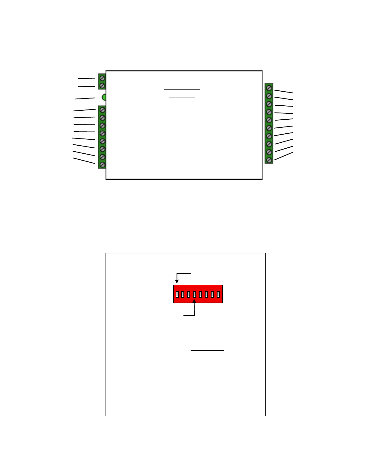
Switch
6 7 8
0
1 x
2 x
3 x x
4 x
5 x x
6 x x
7 x x x
Wiegand
Wiegand / No Filter
Strobed Rising Edge (MR-5)
Strobed Rising Edge (Dorad0 644)
Strobed Rising (Mag-Tek)
Strobed Falling Edge
Reserved
F2F
x = ON
1234567
8
Dip switch #4 is ON
-Enable Pullup resistors
Dip switch #4 is OFF
-Disable Pullup resistors
1 - 8 to 16 VDC In
2 - Ground
Status LED
1 - exp (+)
2 - exp (-)
3 - +5 VDC out
4 - R4
5 - R3
6 - LED out
7 - D1/Data In
8 - D0/Clk In
External connections and DIP Switch Settings
WMR-9600
Remote
1- Relay 2 N.O.
2- Relay 2 Com
3 - Relay 2 N.C.
4 - Relay 1 N.O.
5 - Relay 1 Com
6 - Relay 1 N.C.
7 - Ground
8 - Aux in
9 - Not used
10 - Not used
Remote Unit Settings
DIP Switch #1 ON
-Service Mode
DIP Switch #1 OFF
-Run Mode
Page 3 of 14
1234567
8
Wiegand
Wiegand / No Filter
Strobed Rising Edge (MR-5)
Strobed Rising Edge (Dorad0 644)
Strobed Rising (Mag-Tek)
Strobed Falling Edge
Reserved
F2F
x = ON
Switch
6 7 8
0
1 x
2 x
3 x x
4 x
5 x x
6 x x
7 x x x
Resistors
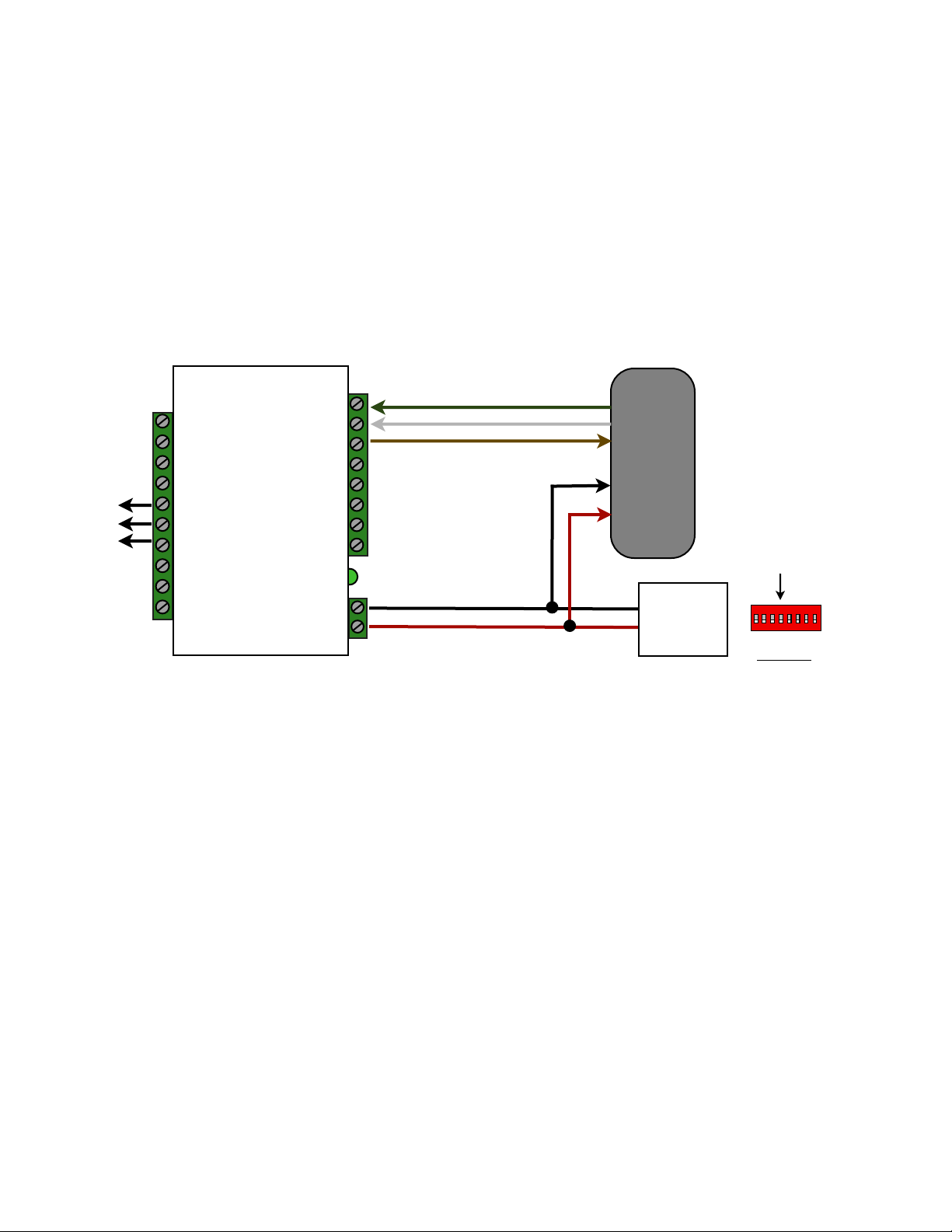
Quick Reference For Typical Connections
WMR-9600 Series Central Quick Reference
WMR-9600 Remote Quick
Door
Strike
R1 N.C.
R1 Com
R1 N.O.
Suprex Remote
D0/Clock In
D1/Data In
LED Out
Ground
+8 to +16 VDC
D0/Clock
D1/Data
LED
Diagnostic LED
Typical Suprex Remote
Connections
(-)
(+)
Card
Reader
Power
Supply
Switch #4 ON
Enable Pullup Resistors
Switch #4 OFF
Disable Pullup
DC
Page 4 of 14
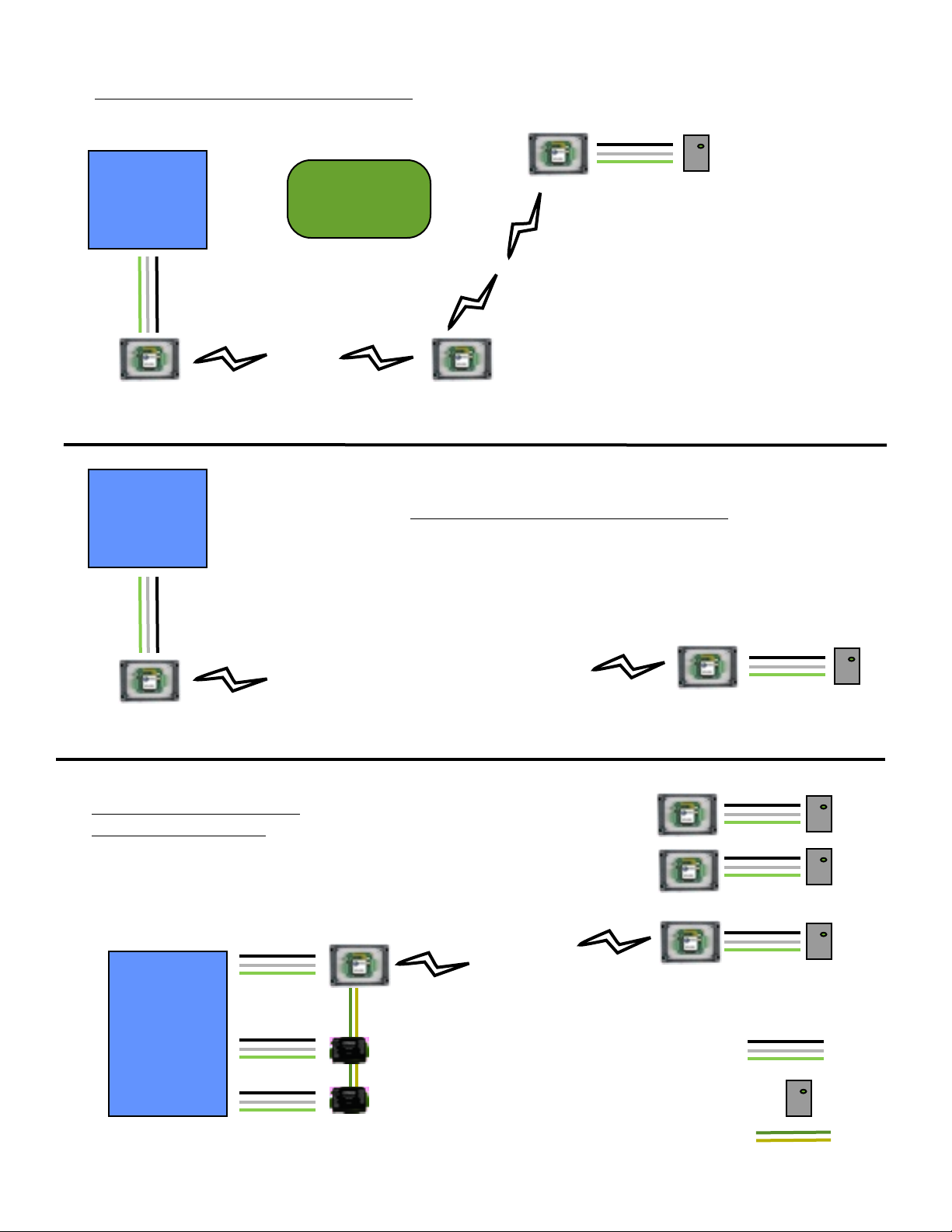
ACS
Typical RF installation with repeater
ACS
Obstruction
WMR-7100 WMR-7500
Typical RF installation - line of sight
WMR-9621 (1)
WMR-7100
Typical RF installation expansion modules
ACS
WMR-7100 (1)
EXP-1000C (2)
WMR-9621(1)
WMR-9621 (1)
WMR-9621 (2)
WMR-9621 (3)
Wiegand connection
Page 5 of 14
EXP-1000C (3)
card reader
RS-485 multi-drop
 Loading...