


!
Operations Manual
Suprex® Reader Extender
SPX-1300
*/5&(3"5*0/40-65*0/4
CYPRESS
"
"
"
"
"
"
"
"
"
"
"
"
"
"
"
"
"
"
"
"
"
"
"
"
"
"
"
"
"
"
"
"
"
"
q! `123458r!
"
"
"
"
"
"
"
"
"
"
"
"
"
"
"
"
Electrical and Mechanical Specifications
Physical
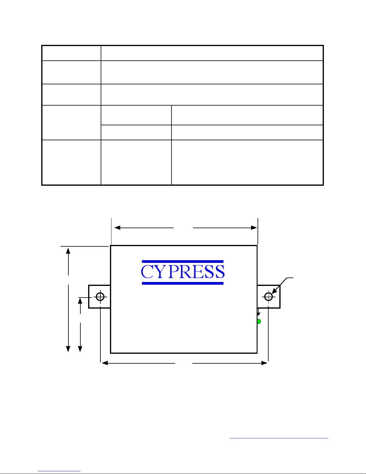
SPX-1300 Aluminum Enclosure 3.5" x 2.75" x .75"
Temp
Storage(-55˚C to + 150˚C)"
Operating(-40˚C to +80˚C)
Humidity
95% (non-condensing)
Power
Input
Unreg Input 8 to 16 VDC* @ 200mA Max
Output
+5VDC @100mA
Data I/O"
Voltage Ratings
Interface
Reader 0- 30VDC"
LED - 0 - 30VDC"
Analog 0 - 5 VDC"
*See Notes on following page for temperature and power ratings
3.3”
DataBender CVX-1300
2.8”
1.4”
3.65”
ø 0.15”
External Dimensions and Mounting Holes
Unit Height = 0.75”
This complies with part 15 of the FCC rules !
Operation is subject to the following two conditions: !
(1) This device may not cause harmful interference, and !
(2) this device must accept any interference received, including
interference that may cause undesired operation.
Cypress Computer Systems, Inc. ⌖ Lapeer, MI 48446 ⌖ www.cypresscomputer.com
© 2012 Cypress Computer Systems Inc.

"
"
"
"
"
"
"
"
"
"
"
"
"
"
"
"
"
"
"
"
"
"
"
"
"
"
"
"
"
"
"
"
"
"
"
"
"
"
"
"
"
"
"
"
"
"
"
"
"
"
"
External connections and DIP Switch Settings
8-485(+)"
7-485(-)"
6-+5 VDC Out"
5-Prog Res 2"
4-Prog Res 1"
3-LED Input"
2-D1/Data/F2F Out-"
1-D0/CLK Out
2-8 to 16 VDC In"
1-Ground
Diagnostic LED
12-RLY4 N.O."
11-RLY4 Com"
10-RLY4 N.C."
9-RLY3 N.O."
8-RLY3 Com"
7-RLY3 N.C."
6-RS232 Out"
5-RS232 In"
4-Ground"
3-Aux Out"
2-Relay2 Input"
1-Relay1 Input"
*
Central Unit
2-8 to 16 VDC In"
1-Ground
12-RLY2 N.O."
11-RLY2 Com"
10-RLY2 N.C."
9-RLY1 N.O."
8-RLY1 Com"
7-RLY1 N.C."
6-RS232 Out"
5-RS232 In"
4-Ground"
3-Aux In"
2-N/C"
1-N/C"
8-485(+)"
7-485(-)"
6-+5 VDC Out"
5-RLY4 Input (5V)"
4-RLY3 Input (5V)"
3-LED Output"
2-D1/Data/F2F Input"
1-D0/CLK Input
*
Remote Unit
Note: F/2F connections"
support unsupervised "
mode only.
1234567
8
Switch
6 7 8
0
1 x
2 x
3 x x
4 x
5 x x
6 x x
7 x x x
Wiegand
Wiegand / No Filter
Strobed Rising Edge (MR-5)
Strobed Rising Edge (Dorad0 644)
Strobed Rising (Mag-Tek)
Strobed Falling Edge
Reserved
F2F
x = ON
Dip switch #4 is ON
-Disable Pullup resistors
Dip switch #4 is OFF
-Enable Pullup resistors
DIP Switch #1 ON "
-Service Mode"
DIP Switch #1 OFF"
-Run Mode
Central Unit !
Settings
Switch
6 7 8
0
1 x
2 x
3 x x
4 x
5 x x
6 x x
7 x x x
Wiegand
Wiegand / No Filter
Strobed Rising Edge (MR-5)
Strobed Rising Edge (Dorad0 644)
Strobed Rising (Mag-Tek)
Strobed Falling Edge
Reserved
F2F
x = ON
Remote Unit !
Settings
1234567
8
Dip switch #4 is ON
-Enable Pullup resistors
Dip switch #4 is OFF
-Disable Pullup resistors
DIP Switch #1 ON "
-Service Mode"
DIP Switch #1 OFF"
-Run Mode

"
"
"
"
"
"
"
"
"
"
"
"
"
"
"
"
"
"
"
"
"
"
"
"
"
"
"
"
"
"
81012
14
16
805535
-40
Ambient Temperature
(Degrees Celsius)
Supply Voltage
Temperature/Voltage de-rating curve
Electrical and Environmental Specifications
The SPX-1300 units should be operated with a filtered 12 Volt nominal DC supply. "
However, any voltage between 8 and 16 volts can be utilized by following the temperature /voltage derating curve.
Voltage should not exceed 16 VDC."
"
Digital Data (D0/D1) Inputs and Outputs are OpenCollector with switchable 1k pullup resistors.."
"
Data I/O Points are rated for the following voltages:"
0 - 5 VDC with pullups on "
0- 24 VDC with pullups off"
"
All Digital Inputs and Outputs are 0 - 24 VDC tolerant . Pullup resistors should be disabled when using I/O at voltages
greater than 5VDC to prevent excessive current draw and possible component damage. "
"
Analog Inputs are rated for 5 VDC max."
The Relay 3, Relay 4 inputs and Programming resistor inputs are analog inputs and are limited to 5 volts DC Maximum."
"
All inputs and outputs are provided with transient and static protection."
"
The RS-485 communication channel will provide the best performance using shielded twisted pair wiring. Other wire
types can be used, and performance will depend upon actual field conditions. The Suprex units will typically function
with: Coax, THHN building wire, Cat5 and Cat 3 cable, etc.

"
"
"
"
"
"
"
"
"
"
"
"
"
"
"
"
"
"
"
"
"
"
"
"
"
"
"
"
"
"
"
"
"
"
"
"
"
"
"
"
"
"
"
"
"
"
"
"
"
"
"
When the Suprex units are operating correctly and have a valid communication channel between"
the Remote and Central units the Diagnostic indicators on each unit will flash green rapidly "
(2-3 flashed per second)."
"
If the units are not communicating, viewing the diagnostic indicator LED’s may help to determine
the "
nature of the problem."
"
DIAGNOSTIC LED NOT ILLUMINATED:"
"
If the LED(s) are not illuminated on the unit(s) then the unit is not getting power. The Diagnostic
LED’s"
will be illuminated when power is applied."
"
CENTRAL UNIT FLASHING BETWEEN RED/GREEN:"
"
With power applied and no communication path between the Remote and Central, the Central
unit will flash the diagnostic indicator alternately between Red and Green."
"
REMOTE UNIT ILLUMINATED RED:"
"
The Remote unit will diagnostic LED will illuminate solid (not flashing) red if it is not receiving
communication from the Central."
"
REMOTE AND CENTRAL UNITS FLASHING BETWEEN RED/GREEN:"
"
The Central is not Receiving communication from the Remote.
Troubleshooting - Diagnostic Indicators
 Loading...