

Page 1

F2MC-16FX Family MB96300 Series
Setup Guide
Doc. No. 002-06378 Rev. *A
Cypress Semiconductor
198 Champion Court
San Jose, CA 95134-1709
Phone (USA): 800.858.1810
Phone (Intnl): +1 408.943.2600
www.cypress.com
Page 2

Copyrights
© Cypress Semiconductor Corporation, 2008-2016. This document is the property of Cypress Semiconductor Corporation
and its subsidiaries, including Spansion LLC (“Cypress”). This document, including any software or firmware included or
referenced in this document (“Software”), is owned by Cypress under the intellectual property laws and treaties of the
United States and other countries worldwide. Cypress reserves all rights under such laws and treaties and does not,
except as specifically stated in this paragraph, grant any license under its patents, copyrights, trademarks, or other
intellectual property rights. If the Software is not accompanied by a license agreement and you do not otherwise have a
written agreement with Cypress governing the use of the Software, then Cypress hereby grants you a personal, nonexclusive, nontransferable license (without the right to sublicense) (1) under its copyright rights in the Software (a) for
Software provided in source code form, to modify and reproduce the Software solely for use with Cypress hardware
products, only internally within your organization, and (b) to distribute the Software in binary code form externally to end
users (either directly or indirectly through resellers and distributors), solely for use on Cypress hardware product units,
and (2) under those claims of Cypress’s patents that are infringed by the Software (as provided by Cypress, unmodified)
to make, use, distribute, and import the Software solely for use with Cypress hardware products. Any other use,
reproduction, modification, translation, or compilation of the Software is prohibited.
TO THE EXTENT PERMITTED BY APPLICABLE LAW, CYPRESS MAKES NO WARRANTY OF ANY KIND, EXPRESS
OR IMPLIED, WITH REGARD TO THIS DOCUMENT OR ANY SOFTWARE OR ACCOMPANYING HARDWARE,
INCLUDING, BUT NOT LIMITED TO, THE IMPLIED WARRANTIES OF MERCHANTABILITY AND FITNESS FOR A
PARTICULAR PURPOSE. To the extent permitted by applicable law, Cypress reserves the right to make changes to this
document without further notice. Cypress does not assume any liability arising out of the application or use of any product
or circuit described in this document. Any information provided in this document, including any sample design information
or programming code, is provided only for reference purposes. It is the responsibility of the user of this document to
properly design, program, and test the functionality and safety of any application made of this information and any
resulting product. Cypress products are not designed, intended, or authorized for use as critical components in systems
designed or intended for the operation of weapons, weapons systems, nuclear installations, life-support devices or
systems, other medical devices or systems (including resuscitation equipment and surgical implants), pollution control or
hazardous substances management, or other uses where the failure of the device or system could cause personal injury,
death, or property damage (“Unintended Uses”). A critical component is any component of a device or system whose
failure to perform can be reasonably expected to cause the failure of the device or system, or to affect its safety or
effectiveness. Cypress is not liable, in whole or in part, and you shall and hereby do release Cypress from any claim,
damage, or other liability arising from or related to all Unintended Uses of Cypress products. You shall indemnify and
hold Cypress harmless from and against all claims, costs, damages, and other liabilities, including claims for personal
injury or death, arising from or related to any Unintended Uses of Cypress products.
Cypress, the Cypress logo, Spansion, the Spansion logo, and combinations thereof, PSoC, CapSense, EZ-USB, F-RAM,
and Traveo are trademarks or registered trademarks of Cypress in the United States and other countries. For a more
complete list of Cypress trademarks, visit cypress.com. Other names and brands may be claimed as property of their
respective owners.
F2MC-16FX Family MB96300 Series Setup Guide, Doc. No. 002-06378 Rev. *A 2
Page 3

Contents
1. Setup Procedures .......................................................................................................................................................... 4
2. Hardware Configuration ................................................................................................................................................ 5
3. Hardware Setup ............................................................................................................................................................. 7
3.1 Setting up the emulator and each board ................................................................................................................ 7
3.2 Jumper settings on the adapter board ................................................................................................................... 8
Revision History ................................................................................................................................................................... 11
Document Revision History ........................................................................................................................................... 11
F2MC-16FX Family MB96300 Series Setup Guide, Doc. No. 002-06378 Rev. *A 3
Page 4
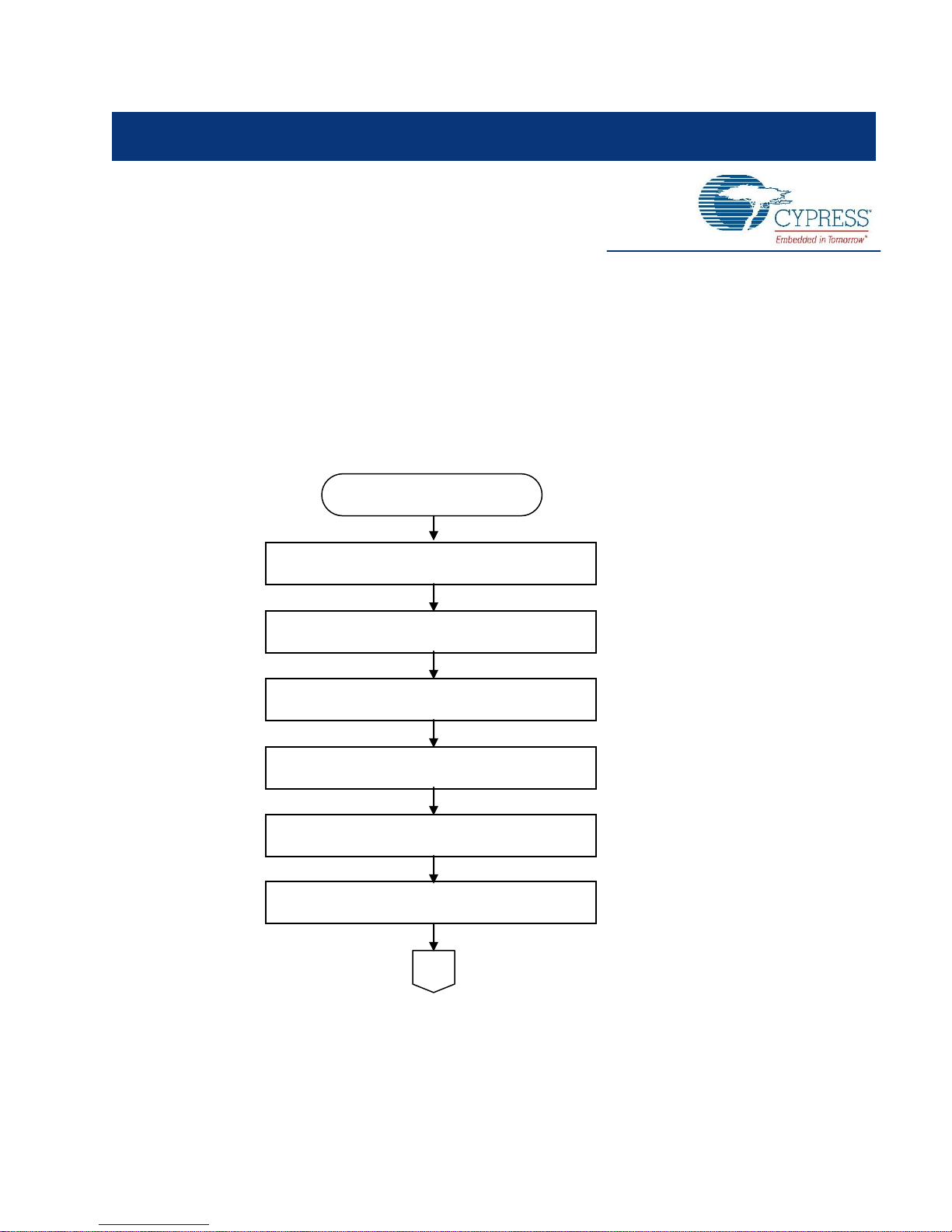
1. Setup Procedures
Start of Setup
Connect emulator, each board (see P7)
Setup the adapter board (see P8)
Power up the emulator
Power up the target board
Launch the debugger (*)
Start debugging
Launch SOFTUNE (*)
This document explains the debug environment and setup procedures for the Cypress MB96300 series of 16-bit
microcontrollers.
Figure 1-1 shows the flow for the setup procedure for the MB96300 series debug environment. The connections for the
emulator and each board, as well as the procedures and descriptions for settings on the adapter board are explained in
the following chapters. Refer to the SOFTUNE Setup Guide for procedures on launching SOFTUNE and the debugger.
Figure 1-1. Flow of Setup Procedures
*Refer to “SOFTUNE Setup Guide.”
F2MC-16FX Family MB96300 Series Setup Guide, Doc. No. 002-06378 Rev. *A 4
Page 5

2. Hardware Configuration
Host PC
Target board
(user board)
Header board
Evaluation chip
Oscillator clock
Adapter board
Emulator
Figure 2-1 shows the configuration of the MB96300 series debug environment. The debug environment consists of a host
PC, emulator (MB2198-01), evaluation chip (MB96V300BRB-ES), adapter board (MB2198-500), header board, and target
board (user board). The SOFTUNE integrated development environment must be setup on the host PC. (Refer to the
SOFTUNE First Step Guide for setup procedures.) Select and use the header board that matches the chip and package
for the device to be used. The model numbers for the header boards with matching device types are listed in Table 2-1.
Also note it is necessary to install a socket (NQPACK) for connecting the header board to the target board (user board).
Figure 2-1. Configuration of Debug Environment
F2MC-16FX Family MB96300 Series Setup Guide, Doc. No. 002-06378 Rev. *A 5
Page 6

Hardware Configuration
Evaluation
product
Evaluation chip
Emulator
Adapter board
Header board
Remarks
MB96320
MB96V300BRB-ES
MB2198-01
MB2198-500
MB2198-505
LQFP-80
MB96340
MB2198-501
QFP-100
MB2198-502
LQFP-100
MB96350
MB2198-503
LQFP-64
(0.5 mm, 10 10 mm)
MB2198-504
LQFP-64
(0.65 mm, 12 12 mm)
MB96380
MB2198-16FX120P-M21
LQFP-120
Table 2-1. Debug Environment Parts for Each Device Type
*The user must also supply a target board (user board), and oscillator clock (crystal oscillator).
F2MC-16FX Family MB96300 Series Setup Guide, Doc. No. 002-06378 Rev. *A 6
Page 7

3. Hardware Setup
Adapter board
(MB2198-500)
Flat cable
(supplied with
adapter board)
Emulator (MB2198-01)
Mount evaluation chip
(MB96V300BRB-ES) in IC
socket
Connect AC adapter
Connect host PC to emulator
Use flat cable (supplied with
adapter board) to connect to
the header board
1 pin
Evaluation M C U
(MB96V300
BRB-ES)
Host PC
External trigger/ program execution
General purpose measuring device
AC adapter
User system
Header board
AC in
Adapter board
This chapter explains the setup procedures the MB96300 series debug environment.
3.1 Setting up the emulator and each board
Figure 3-1 shows the connections for the emulator and each board. Connect each board shown in Figure 3-1. The
included AC adapter must be used to provide power to the emulator. Also, the evaluation chip (MB96V300BRB-ES) must
be mounted to the adapter board.
Figure 3-1. Connections for the Emulator and Each Board
F2MC-16FX Family MB96300 Series Setup Guide, Doc. No. 002-06378 Rev. *A 7
Page 8

Hardware Setup
MD0, MD1, MD2
= USR side
*1 User must supply a
crystal oscillator rated
for the frequency used
in the user system.
DVDD
=USR side
MD0_SEL, MD1_SEL,
MD2_SEL=L side
Oscillator clock *1
(crystal oscillator)
X0, X1
=EML side
X0A, X1A
=EML side
CLKSEL0, CLKSEL1
=PORT side *2
AVCC_IN
=A-B side
AVCC_OUT
=USR side
AVRH_IN
= A-B side
AVRH_OUT
=USR side
AVRL_IN
= A-B side
AVRL_OUT
=USR side
AVSS_OUT
=USR side
C =EML side
RTSX
=USR side
3.2 Jumper settings on the adapter board
Jumper pins are provided on the adapter board and must be set according to the operating conditions. The figure below
shows the location for the jumper pins that need to be set. Each jumper pin setting is described in Table 3-1 to Table 3-4.
The recommended jumper pin settings are shown highlighted in gray (■). Set the jumper pins on the adapter board
according to the descriptions in the tables.
Figure 3-2. Jumper Pin Locations on the Adapter Board
*2 If a sub clock is to be used, set the jumper on the adapter board to the CLK side, then connect the sub clock to the IC
socket for the crystal oscillator.
F2MC-16FX Family MB96300 Series Setup Guide, Doc. No. 002-06378 Rev. *A 8
Page 9

Hardware Setup
Jumper
Setting
Description
DVDD
DBG side
Supply DC regulated power supply from connection at UVCC connector (CN7).
USR side (default)
Supply DVCC power supply from the user system.
RSTX
DBG side
Fix RSTX to “H” using DC regulated power supply from connection at UVCC connector
(CN7).
USR side (default)
Supply the RTSX signal from the user system.
MD2,MD1,
MD0
DBG side
Supply the mode pin signal on the adapter board.
USR side (default)
Supply the mode pin signal from the user system.
MD2_SEL,
MD1_SEL
MD0_SEL
H side
These jumpers set the mode pins for the evaluation MCU. These settings are enabled when
the MD2-MD0 jumpers are set to the DBG side.
Each signal level is set to the output level of the DC regulated power supply connect to the
UVCC connector (CN7).
L side (default)
Jumper
Setting
Description
X1,
X0
USR side
Supply the main clock from the user system
EML side (default)
Supply the main clock from the crystal oscillator IC socket on the adapter board
X1A,
X0A
USR side
Supply the sub clock from the user system
EML side (default)
Supply the sub clock from the crystal oscillator IC socket on the adapter board
CLKSEL1,
CLKSEL0*
PORT side (default)
Use the port/sub clock input pin (P040/X0A, P041/X1A) as a port
CLK side
Use the port/sub clock input pin (P040/X0A, P041/X1A) as the sub clock input pin
Table 3-1. Jumper Settings on the Adapter Board (Debug power supply selection)
Table 3-2. Jumper Settings on the Adapter Board (Short plug settings for clock changeover)
* If a sub clock is to be used, set the jumper on the adapter board to the CLK side, and then connect the sub clock to the
IC socket for the crystal oscillator.
F2MC-16FX Family MB96300 Series Setup Guide, Doc. No. 002-06378 Rev. *A 9
Page 10

Hardware Setup
Jumper
Setting
Description
AVCC_IN
A-B side (default)
Select the analog power supply (AVCC) from the user system
A-C side
Select the analog power supply (AVCC), with an RC filter, from the user system
B-D side
Select the analog power supply (VDD) from the UVCC connector
C-D side
Select the analog power supply (VDD), with an RC filter, from the UVCC connector
AVCC_OUT
USR side (default)
Supply the power supply selected by AVCC_IN to the evaluation MCU analog power supply
(AVCC)
FLT side
Add an RC filter to the power selected by AVCC_IN and supply to the evaluation MCU
analog power supply (AVCC)
AVRH_IN
A-B side (default)
Select the analog power supply (AVRH) from the user system
A-C side
Select the analog power supply (AVRH), with an RC filter, from the user system
B-D side
Select the analog power supply (UVDD) from the UVCC connector
C-D side
Select the analog power supply (UVDD), with an RC filter, from the UVCC connector
AVRH_OUT
USR side (default)
Supply the power supply selected by AVRH_IN to the evaluation MCU analog power supply
(AVRH)
FLT side
Add an RC filter to the power selected by AVRH_IN and supply to the evaluation MCU
analog power supply (AVRH)
AVRL_IN
A-B side (default)
Select the analog power supply (AVRL) from the user system
A-C side
Select the analog power supply (AVRL), with an RC filter, from the user system
B-D side
Select the analog power supply (VDD) from the UVCC connector
C-D side
Select the analog power supply (VDD), with an RC filter, from the UVCC connector.
AVRL_OUT
USR side (default)
Supply the power supply selected by AVRL_IN to the evaluation MCU analog power supply
(AVRL)
FLT side
Add an RC filter to the power selected by AVRL_IN and supply to the evaluation MCU analog
power supply (AVRL)
AVSS_OUT
USR side (default)
Connect the analog power supply (AVSS) from the user system to the evaluation MCU
analog power supply (AVSS)
GND side
Connect the GND and evaluation MCU analog power supply (AVSS)
Jumper
Setting
Description
C
USR side
Connect the capacitor on the user system to the C pin on the evaluation MCU
EML side (default)
Connect the capacitor on the adapter to the C pin on the evaluation MCU
Table 3-3. Jumper Settings on the Adapter Board (Short plug settings for analog power supply changeover
Table 3-4. Jumper Settings on the Adapter Board (Short plug settings for C pin supply)
Refer to the Instruction Manual for the Adapter MB2198-500 for details on settings of the adapter board.
F2MC-16FX Family MB96300 Series Setup Guide, Doc. No. 002-06378 Rev. *A 10
Page 11

Revision History
Document Title: F2MC-16FX Family MB96300 Series Setup Guide
Document Number: 002-06378
Revision
Issue Date
Origin of
Change
Description of Change
**
09/11/2008
KHAS
Initial release.
*A
05/16/2016
KHAS
Migrated Spansion Guide from AN07-00160-1E to Cypress format.
Document Revision History
F2MC-16FX Family MB96300 Series Setup Guide, Doc. No. 002-06378 Rev. *A 11
 Loading...