


DCT-35
Optical & L/R to L/R Audio Controller
Operation Manual
Operation Manual


DISCLAIMERS
The information in this manual has been carefully checked and
is believed to be accurate. Cypress Technology assumes no
responsibility for any infringements of patents or other rights of third
parties which may result from its use.
Cypress Technology assumes no responsibility for any inaccuracies
that may be contained in this document. Cypress also makes no
commitment to update or to keep current the information contained
in this document.
Cypress Technology reserves the right to make improvements to this
document and/or product at any time and without notice.
COPYRIGHT NOTICE
No part of this document may be reproduced, transmitted,
transcribed, stored in a retrieval system, or any of its part translated
into any language or computer le, in any form or by any means—
electronic, mechanical, magnetic, optical, chemical, manual, or
otherwise—without express written permission and consent from
Cypress Technology.
© Copyright 2012 by Cypress Technology.
All Rights Reserved.
Version 1.0 January 2012
TRADEMARK ACKNOWLEDGMENTS
All products or service names mentioned in this document may be
trademarks of the companies with which they are associated.

SAFETY PRECAUTIONS
Please read all instructions before attempting to unpack, install or
operate this equipment and before connecting the power supply.
Please keep the following in mind as you unpack and install this
equipment:
• Always follow basic safety precautions to reduce the risk of re,
electrical shock and injury to persons.
• To prevent re or shock hazard, do not expose the unit to rain,
moisture or install this product near water.
• Never spill liquid of any kind on or into this product.
• Never push an object of any kind into this product through any
openings or empty slots in the unit, as you may damage parts
inside the unit.
• Do not attach the power supply cabling to building surfaces.
• Use only the supplied power supply unit (PSU). Do not use the PSU
if it is damaged.
• Do not allow anything to rest on the power cabling or allow any
weight to be placed upon it or any person walk on it.
• To protect the unit from overheating, do not block any vents or
openings in the unit housing that provide ventilation and allow for
sufcient space for air to circulate around the unit.
REVISION HISTORY
VERSION NO. DATE DD/MM/YY SUMMARY OF CHANGE
VR0 05/03/15 Preliminary Release

CONTENTS
1. Introduction ..........................................................................1
2. Applications .........................................................................1
3. Package Contents ..............................................................1
4. System Requirements .......................................................... 1
5. Features ................................................................................1
6. Operation Controls and Functions ..................................... 2
6.1 Front Panel ...................................................................... 2
6.2 Rear Panel .......................................................................2
6.3 IP Searching Software Application and Installation ..3
6.4 Telnet Commands..........................................................5
6.5 Telnet Control .................................................................6
6.6 Web GUI Control ............................................................ 8
7. Connection Diagram ..........................................................9
8. Specications ��������������������������������������������������������������������������� 10

1. INTRODUCTION
The Optical & L/R to L/R Audio Controller allows user with exible and
distance control over audio performance. With L/R & Optical inputs
to L/R output, this device provides a digital to analog conversion or
analog to analog bypass function. Controls like Telnet & WebGUI allow
user with easy adjustment and remote over audio output. On-panel
control with LED indication adds-on the friendly use for the device.
2. APPLICATIONS
• Entertainment Room / Home Theater
• Show Room / Demo Room
• Audio equipment central control
3. PACKAGE CONTENTS
• Optical & L/R to L/R Audio Controller
• 5V / 2.6A DC power supply
• Operation Manual
4. SYSTEM REQUIREMENTS
Input source equipment such as CD /DVD player or computer via
optical or analog stereo output to amplier or speaker with analog
stereo output.
5. FEATURES
• Support optical input sampling rate up to 192kHz
• Supports Optical & L/R inputs to L/R output
• Support Stereo out or Mono out
• Support Volume control by Telnet or WebGUI
• Control switch by single button press
1

6. OPERATION CONTROLS AND FUNCTIONS
6.1 Front Panel
POWERIN
CONTROLOPTICAL
OUT
RL
AUDIO CONTROLLER
1 32 4 5
1
IN Button: Short press IN button to switch the audio source. Long
press IN button up to 4 seconds will reset the device to Default
Ethernet Setting. The Power LED will blink 5 times.
2
POWER LED: When power is on, the LED light will illuminate.
3
OPTICAL LED: When source switch to Optical input selection, the
LED light will illuminate. When switch to L/R the LED will unilluminate.
4
CONTROL: This slot is to connect with intranet service line for telnet/
WebGUI control.
5
L/R OUT: These slots are to connect with active speakers or
amplier’s L/R inputs.
6.2 Rear Panel
OPTICAL
IN
L
R
SERVICE DC 5V
1 3 4
1
OPTICAL IN: This slot is to connect with input source’s optical output
2
port.
2
L/R IN: These slots are to connect with input source’s L/R output
port.
3
SERVICE: This slot is reserved for USB rmware update use only.
4
DC 5V: Connect the adaptor included in the package and
connect to AC wall outlet for power supply.
2

6.3 IP Searching Software Application and Installation
Please download the software from www.cypress.com.tw with le
name CDPS V2.000 and save it in a directory where you may use it
later.
Connect the AUDIO CONTROLLER with an active network system and
open the CDPS V2.000 application from the directory in a PC/Laptop.
Click on Find Devices on Network and a list of the devices will show
up.
Double click on the product name and an InfoFrom page will appear
to show the products’ detail or use the IP Address listed to control the
device directly.
3

Default Ethernet Setting is on Static mode with:
IP: 192.168.1.50
SUBNET: 255.255.255.0
GATEWAY: 192.168.5.254
HTTP PORT: 80
TLENET PORT: 23
4

6.4 Telnet Commands
Command Name Description Description of parameter
SOURCE N SOURCE SELECTION N=0/Optical, 1/RCA IN or
VOL N
MUTE N
MONO N
NAME N1 N2 SET INPUT NAME
IPCONFIG
SIPADDR N
SNETMASK N
SGATEWAY N
RSTIP
VER
REBOOT SYSTEM REBOOT None
FADEFAULT FACTORY RESET None
ETH_FADEFAULT
?
HELP
Note: All the RS-232 command will be not executed unless followed
with a carriage return. All commands are case-sensitive
OUTPUT VOLUME
SETTING
OUTPUT VOLUME
MUTE CONTROL
SET MOMO OR
STEREO MODE
SHOW IP
CONFIGURATION
STATUS
SET ETHERNET IP
ADDRESS
SET ETHERNET
NETMASK
SET ETHERNET
GATEWAY
IP CONFIGURATION
RESET TO <DHCP>
SHOW UNIT
FIRMWARE VERSION
ETHERNET
PARAMETER SET
FACTORY DEFAULT
SHOW COMMAND
LIST
SHOW COMMAND
LIST
N=-40~10dB (0) or
N=0(Unmute), 1(Mute) or
N=0(Stereo), 1(Mono) or
N1=0(Optical), 1(RCA)
N2=Up to 24 Characters or
None
N=X.X.X.X
X=0~255 (192.168.1.50)
N=X.X.X.X
X=0~255 (255.255.255.0)
N=X.X.X.X
X=0~255 (192.168.5.254)
None (Statics)
None
None
None
None
?
?
?
?
?
5

6.5 Telnet Control
To access the telnet control in Windows 7, click on ‘Start’ menu and
type “cmd” in the Search eld then press enter.
Under Windows XP go to the ‘Start’ menu and click on “Run”, type
“cmd” and press enter.
Under Mac OS X, go to Go→Application→Utilities→Terminal
Once in the command line interface (CLI) type “telnet”, then the IP
address of the unit and hit enter.
Type HELP or ? to bring out all the commands.
6
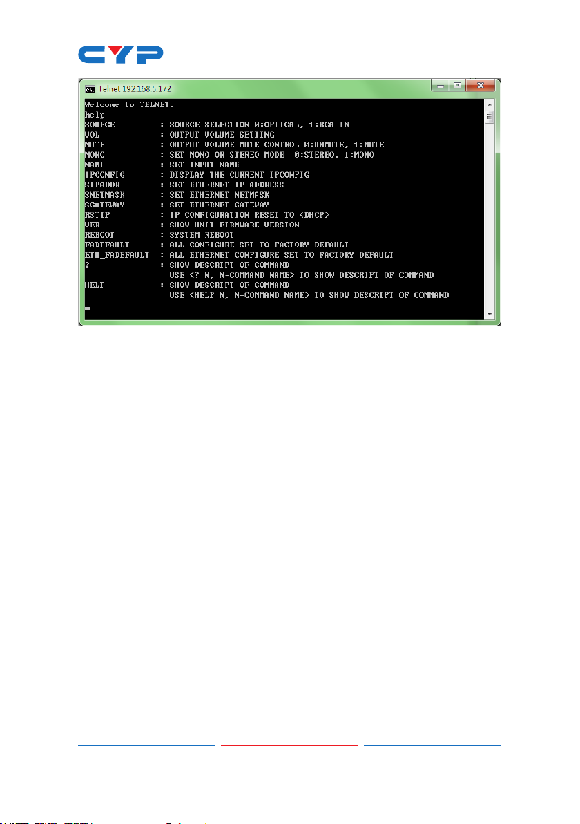
Note: All the commands will be not executed unless followed by a
carriage return. Commands are case-insensitive. If the IP is changed
then the IP Address required for Telnet access will also change
accordingly.
7
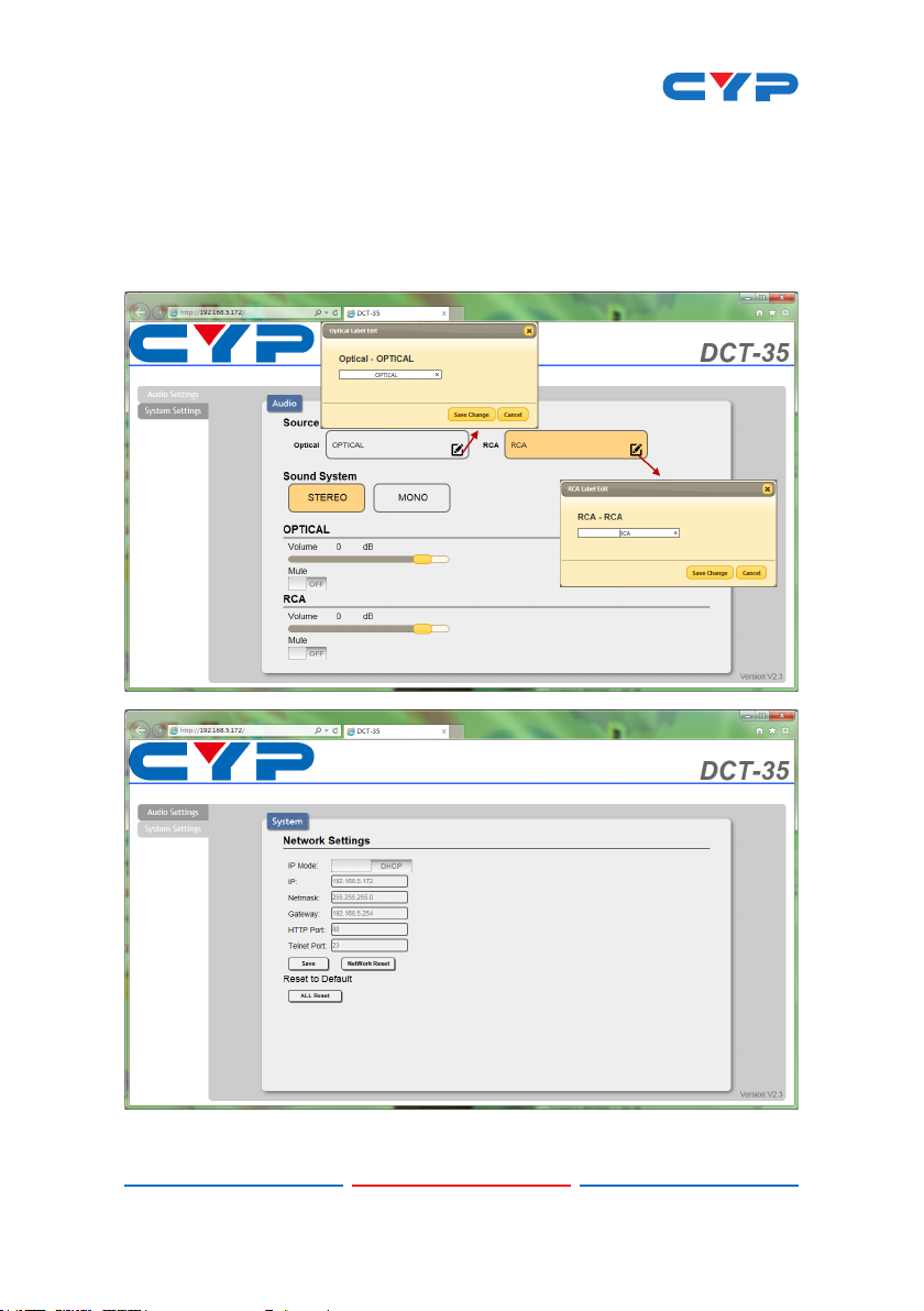
6.6 Web GUI Control
On a PC/Laptop that is connected to an active network system, open
a web browser and type device’s IP address on the web address entry
bar. The browser will display the device’s Audio and System
Settings for users to control.
8
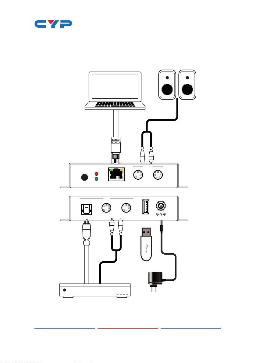
7. CONNECTION DIAGRAM
PC/Laptop Speakers
OUT
RL
AUDIO CONTROLLER
SERVICE DC 5V
OPTICAL
POWERIN
CONTROLOPTICAL
IN
L
R
Media Player
9

8. SPECIFICATIONS
Input Ports 1 x RJ45(Control)
Output Ports 1 x L/R
Power Supply 5VDC/2.6A (US/EU standards, CE/
ESD Protection Human body model:
Chassis Material Metal
Silkscreen color Black
Dimensions 55mm (W) x82mm (D) x 22.5mm (H)
weight 342g
Operating Temperature 0˚C~40˚C / 32˚F ~ 104˚F
Storage temperature -20˚C~60˚C / -4˚F ~ 140˚F
Relative Humidity 20~90% RH (no condensation)
Power Consumption 2w
1 x L/R
1 x Optical
1 x USB(service)
FCC/ UL certied)
±8kV (air-gap discharge)
±4kV (contact discharge)
Audio Specication
Input Output Output
Level
Optical
0dBFS
1kHz
L/R
2Vrms
1kHz
L/R 2Vrms±10% <0.01% ±1dBFS >80dB <-80dB
L/R 2Vrms±10% <0.01% ±1dBFS >80dB <-80dB
T.H.D+N
(A-Weight)
Frequency
Response
SNR Crosstalk
10

CYPRESS TECHNOLOGY CO., LTD
Home page: http://www.cypress.com.tw
201510116 MPM-DCT35
 Loading...