

Page 1
CP-255DN
HTCP-255DN
PC/HD to 1080p DVI Scaler Box
Operation Manual
Operation Manual
Page 2

SAFETY PRECAUTIONS
Please read all instructions before attempting to unpack, install or
operate this equipment and before connecting the power supply.
Please keep the following in mind as you unpack and install this
equipment:
• Always follow basic safety precautions to reduce the risk of fi re,
electrical shock and injury to persons.
• To prevent fi re or shock hazard, do not expose the unit to rain,
moisture or install this product near water.
• Never spill liquid of any kind on or into this product.
• Never push an object of any kind into this product through any
openings or empty slots in the unit, as you may damage parts
inside the unit.
• Do not attach the power supply cabling to building surfaces.
• Use only the supplied power supply unit (PSU). Do not use the PSU
if it is damaged.
• Do not allow anything to rest on the power cabling or allow any
weight to be placed upon it or any person walk on it.
• To protect the unit from overheating, do not block any vents or
openings in the unit housing that provide ventilation and allow for
suffi cient space for air to circulate around the unit.
REVISION HISTORY
VERSION NO. DATE DD/MM/YY SUMMARY OF CHANGE
VR0 17/10/13 Preliminary Release
VR1 16/07/14 Output format
Page 3

CONTENTS
1. Introduction ............................................ 1
2. Features .................................................. 1
3. Package Contents ................................ 1
4. Operation Controls and Functions ....... 2
4.1 Front Panel ........................................2
4.2 Rear Panel .........................................3
4.3. Remote Control and functions ...... 4
5. Installation .............................................. 5
6. OSD Operation ....................................... 8
6.1 Video (or PC) ....................................8
6.2 Color ................................................10
6.3 Output .............................................10
6.4 OSD Adjust ......................................10
6.5 Information ......................................10
7. Specifi cations ......................................11
Page 4

1. INTRODUCTION
This DVI Scaler is designed to convert PC, SD, HD and DVI to digital DVI
at a variety of HDTV and PC resolutions. It handles input and output
signal at 165MHZ ultra high bandwidth. It also has many great features
to enhance video performance and is ideal for use in professional
large screen presentation.
2. FEATURES
• High bandwidth and professional PC/Component/DVI to DVI Scaler
that accepts PC RGB (up to WUXGA), HD Component (480i up to
1080p) and DVI (up to WUXGA) and scale them up to DVI-I output
(1080p/WUXGA).
• The input analog PC or HDTV signal in the format of either RGBHV,
YPbPr, (YCbCr) or digital DVI.
• The output digital DVI plus analog PC/HD with selectable output
resolution from 480i to 1080p and VGA to WUXGA.
• The input resolution is automatically detected while the output
resolution and refresh rate can be selected through OSD menu or
front panel push buttons.
• Native output resolution ensures most optimal display resolution on
your screen. When "Native" is selected as the output resolution, the
device will automatically detect the native resolution of the display
and send out the most optimal pixel timing to match TV's fi nal
display resolution.
• Output picture adjustment on brightness, contrast, color, RGB level,
and H-V position.
• The DVI input is HDCP compliant which means if input is HDCP
encrypted then DVI output is also HDCP encrypted. In this case the
PC analog output will be turned off.
• Includes advanced features such as Noise Reduction and
overscan/underscan adjustment.
3. PACKAGE CONTENTS
• PC/HD/DVI to DVI scaler box.
• VGA cable x 1
• YPbPr 3RCA cable x 1
• AC power adaptor 5V/ 2.6A, center positive.
1
Page 5
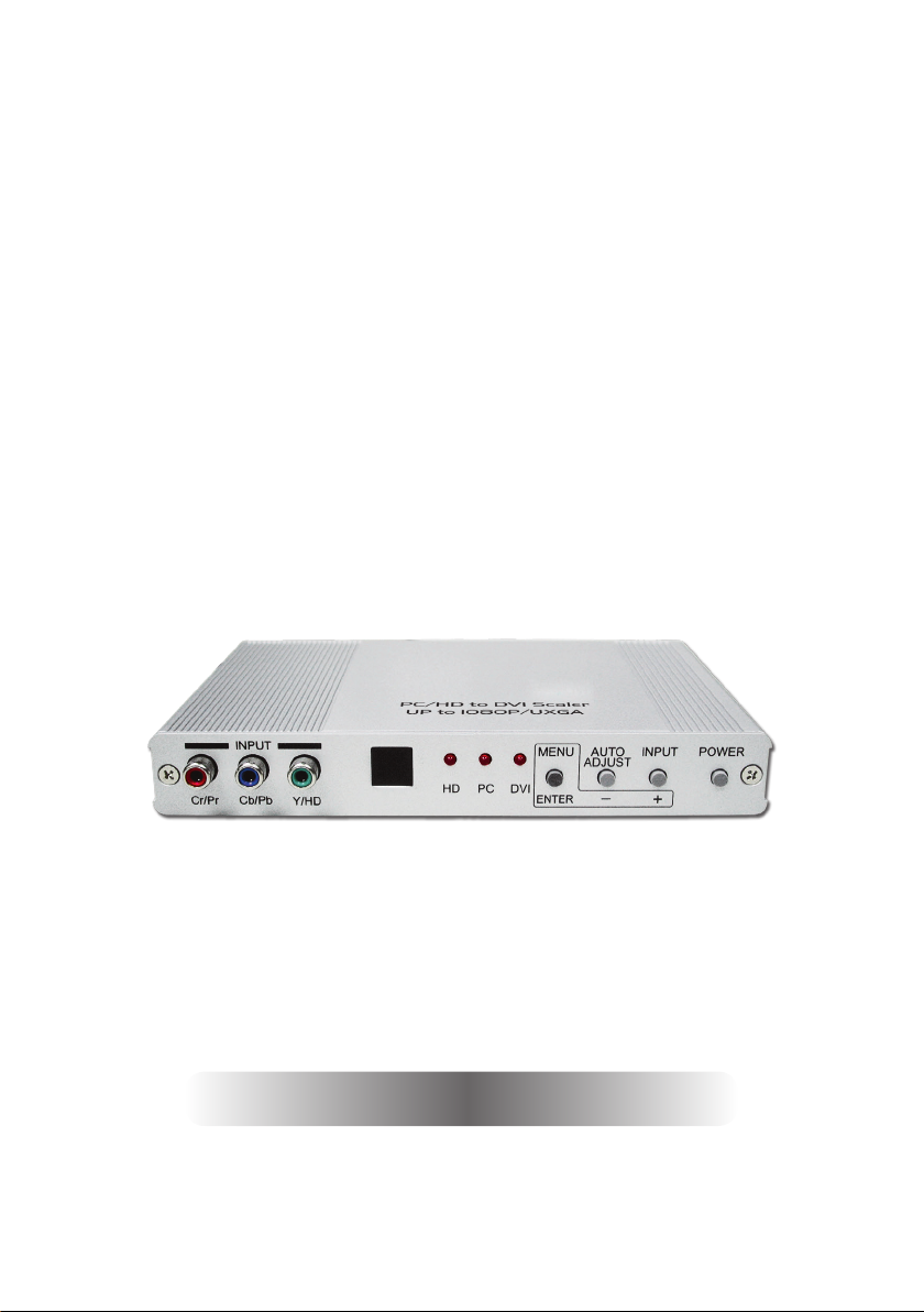
4. OPERATION CONTROLS AND FUNCTIONS
4.1 Front Panel
INPUT
Cb/Pb
Cr/Pr
Y/HD
HD
MENU POWERINPUT
PC DVI
ENTER
AUTO
ADJUST
-
+
3 54 61 2
1
Component Input: Connects this input connector to the
Component output connector of your source equipment using the
enclosed 3RCA to 3RCA cable.
The device accepts both interlaced component input
(480i, 576i) and deinterlaced progressive input (480p, 576p...1080p).
The input range is from 480i, 570i~1080i to 1080p.
2
IR Sensor: Infrared remote control sensor.
3
Input LED Indicators: When one of the LED illuminates its
corresponding source is being selected as input.
4
Menu/Enter: This button serves two purposes.
a. Press the button to bring up OSD main menu as shown in the
"OSD Operation". (page 9)
b. To act as a "Enter" key to enter sub menu or to adjust setting
value of the selected parameter.
5
+/- button: The buttons provide 3 functions:
a. Input select ("+"): Press the "+" button repeatedly to select your
desired input source. The input sources are toggled through in the
following sequence.
YPbPr (YCbCr) PC DVI
b. Auto Tune ("-"): Press the "-" button to carry out picture auto
adjust for analog inputs (component or PC). The device will fi ne
tune the position (centering) and color of the output picture.
c. When in the OSD menu mode: Press the"+", "-" button to move
up or down the highlight bar to your desired parameter. Or once a
parameter is selected with MENU/Enter button, press the button to
2
Page 6

adjust setting value of your selected parameter.
6
Power: Press the button to turn ON or turn OFF (standby) the power
of the unit.
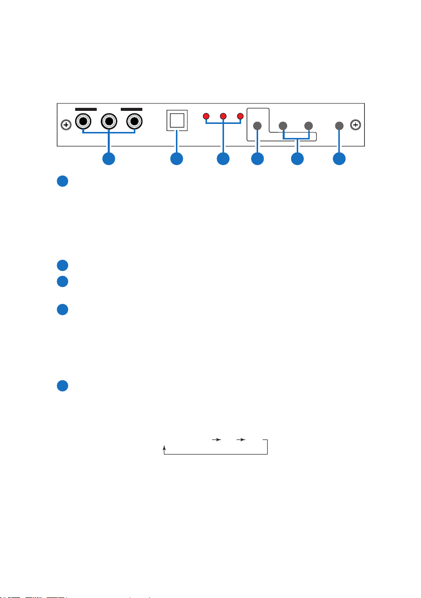
4.2 Rear Panel
DC 5V
PC OUTDVI OUT PC INDVI IN
1 2 3 4 5
1
Power jack: Connect to the 5V 2.6A DC power adaptor.
2
DVI output: Scaled digital DVI output. Connect this output to the
DVI input or HDMI input of your Digital display.
Note: When input is a HDCP encrypted DVI signal the DVI output is
also HDCP encrypted.
The monitor/display that connected to this output also need to be
HDCP compliant in order to get a nice and clean picture. A nonHDCP compliant display can only display non-HDCP signal and
picture will become noise when input is a HDCP-encrypted signal.
3
PC/D-Sub out: The connector for scaled analog RGB output.
Connect this output port to the analog PC RGB input of your
monitor, or connect it to the RGBHV input of your HD display using
D-sub to 5 BNC adaptor cable. (not included in the package)
Note: When input is a HDCP encrypted DVI signal this analog
output will be turned off.
4
DVI input: Connects this DVI input connector to the DVI output
connector of your DVI source equipment. The DVI input should be
digital DVI only and should not include analog RGB signal.
The use of DVI-I connector is to ensure both DVI-I and DVI-D male
connector of the DVI cable can fi t into this input connector.
The digital DVI input resolution can range from 480i~1080p, or
VGA~WUXGA.
5
PC input: Connects this PC input connector to the VGA output of
your PC. The acceptable PC resolutions range from VGA~WUXGA.
3
Page 7

4.3. Remote Control and functions
1
11
12
10
Power: Press the button once to power
ON the device. Press again to enter
standby mode.
2
Input: Press the button repeatedly to
toggle through various input sources as
follows.
3
HD input: Press the button to select
component input.
4
PC input: Press the button to select PC
input.
5
HDMI/DVI input: Press the button to
select DVI (or HDMI) input.
6
Output resolution Select buttons:
Press any one of the button to directly
select output resolution.
For other output resolutions that are not covered by these buttons
please enter Menu/Output page to select them.
7
MENU: Press the button to bring up OSD main menu page.
8
Exit: Press the button to exit from a sub menu or main menu.
9
Up/Down/Left/Right:
Press the Up/Down button to move the highlight bar to your
desired parameter during the OSD operation.
Press the Left/Right button to increase/decrease the setting value
of a selected parameter.
10
OK (Enter): Press the button to confi rm your selection.
11
Reset: Press the button to reset the unit's fi rmware setting to the
factory default value.
12
Auto Adjust: Press the button to optimize the position of the picture
(picture centering) on the screen.
3
6
8
4
12
5
7
9
4
Page 8

5. INSTALLATION
Input Connection
INPUT
Cb/Pb
Cr/Pr
Y/HD
DVD or Set Top Box
DC 5V
HDMI to DVI
connector
adaptor
HD
PC DVI
Component in
Component out
PC OUTDVI OUT PC INDVI IN
DVI
HDMI
HDMI
Cable
MENU POWERINPUT
AUTO
ADJUST
-
ENTER
or
DVI
Cable
+
PC-In
HDMI
Out
DVI
Out
PC
DVD
PC
or
Set-top Box
5
Page 9

The device accepts component, PC and DVI inputs. The formats
supported by these inputs are as follows:
• When connecting to a PC source use a 15-pin D-sub cable to
connect the output of a PC to the D-Sub input connector of the
device.
• When connecting to a component source (either SD or HD
resolution) use a 3RCA to 3RCA cable to connect the YPbPr or
YCbCr output of a DVD or Set Top Box to the Y-Cb/Pb-Cr/Pr input
connecter of the device.
• When connecting to a DVI source, use a DVI-I or DVI-D cable to
connect the DVI output of a PC or DVD to the DVI input connector
of the device.
• When connecting to a HDMI source, use a HDMI cable to connect
to the HDMI output of a HDMI source, such as DVD or STB, on the
one end. And use a HDMI to DVI connector adaptor to connect
to the other end of the HDMI cable. The DVI connector of the
adaptor is then connect to the DVI input of the device.
The device can automatically detect the input resolution of all three
inputs. To switch from one input source to another just press the input
button on the front panel ("+") or on the remote control.
6
Page 10

Output Connection
PC OUTDVI OUT PC INDVI IN
DC 5V
HDMI to DVI
connector
adaptor
or
DVI Cable
DVI
Cable
or
LCD TV
HDMI TV
HDMI TV
RGBHV
LCD or Monitor
The device can output a variety of PC, SD and HD resolutions in
both digital and analog format simultaneously. The digital output is
available from the DVI output connector while the analog output is
available from the PC D-sub output connector.
7
Page 11

6. OSD OPERATION
After power on the unit, press the "menu" button will bring up the main
Main Menu
Video(PC) Color Output
NATIVE
VERSION
menu as follows:
Video (or PC)
Color
Output
OSD
Info
Use +, - button to move highlight bar to your desired parameter, then
press MENU/ENTER to enter into sub-menu of your selected parameter.
6.1 Video (or PC)
When Video is selected a sub menu as below comes up.
Contrast
Brightness
Hue
Saturation
Sharpness
Picture Mode
overscan
Scale
NR
H-position (PC)
V-position (PC)
Exit
underscan
Letterbox
Panscan
Full
low
middle
high
off
user
standard
vivid
movie
Contrast
Brightness
Hue
Sat
Sharpness
Picture Mode
Scale
NR
(H-position)
(V-position)
Exit
User
Normal
Warm
Cool
OSD Info
VGA
SVGA
XGA
SXGA(+)
UXGA
WXGA
WSXGA
WUXGA(+)
480i
480p
576i
576p
720p(50/60)
1080i(50/60)
1080p(50/60)
H.Position
V.Position
Time out
Background
Exit
Source
Input
Output
8
Page 12

Note (PC): Available only when PC is selected as input.
To adjust picture quality, Use "+,-" to move the highlight bar to your
desired adjust item, press the Menu/Enter to confi rm your selection.
At this point, the selected parameter will turn red, you can then use +,to increase or decrease the value of the parameter.
When adjustment is complete, press "Menu" to leave the parameter.
Move the highlight bar to "Exit", then press Menu/Enter to exit.
Note: The "H-position" and "V-position" are only available when
component or PC input is selected. Neither are available when the
DVI input is selected.
Picture mode: There are 4 picture modes for customer to choose from.
User: Select to adjust to your favorite setting and store it.
Standard: Standard factory default setting for optimal display in a
normal environment.
Vivid: High saturation picture for optimal display in a bright room.
Movie: Picture for comfortable low brightness display in a dark room.
Scale: select overscan when input source is SD or HD video to ensure
no black band around screen border. Select underscan when input
source is PC signal to ensure full picture content fall within screen
border.
Noise Reduction: This function only works when input is analog RGB or
component. It will not work for DVI input. There are four steps of
Noise Reduction-Off, Low, Middle High. The Noise Reduction will
remove the noise that results from analog to digital conversion
and digital scaling processing.
H & V position: To adjust for best horizontal and vertical position of the
picture in the screen.
9
Page 13

6.2 Color
User: Select to adjust to your favorite color
temperature setting.
Normal: Normal color tone setting where white is
pure white.
Warm: Warm color tone makes white reddish.
Cool: Cool color tone makes white bluish.
R
0 50 100
G
0 50 100
B
0 50 100
Value of Normal
Setting
6.3 Output
The device can output a wide variety of PC and HD resolutions. Detail
please refer to product specifi cations.
6.4 OSD Adjust
H.Position: Adjust the horizontal position of the OSD graphic.
V.Position: Adjust the vertical position of the OSD graphic.
Time out: Set a predetermined time to turn off OSD menu on the
screen.
Background: To select transparent or solid background of OSD
graphic.
6.5 Information
Source: Show product model number.
Input: Show input resolution i.e. XGA.
Output: Show output resolution i.e. 720p.
VERSION: Show date of fi rmware version.
10
Page 14

7. SPECIFICATIONS
HDMI Compliant
* 1440x480 / 1440x576
Input format (Up to 165MHz)
Resolution INPUT
480i/576i
480p/576p
720p@(60/50)
1080i@(60/50)
1080p@(60/50)
VGA@(60/72/75/85)
SVGA@(56/60/72/75/85)
XGA@(60/70/75/85)
SXGA@(60/75/85)
UXGA@60
WXGA@60(1280X800)
WSXGA@60(1680X1050)
WUXGA@60(1920X1200)
* 480i 30x2 / 576i 25x2
Output format (Up to 165MHz)
Resolution OUTPUT
480i/576i
480p/576p
720p@(60/50)
1080i@(60/50)
1080p@(60/50)
VGA@60(640x480)
SVGA@60(800x600)
XGA@60(1024x768)
SXGA@60(1280x1024)
UXGA@60
WXGA@60(1280X800)
WSXGA@60(1680X1050)
WUXGA@60(1920X1200)
Component D-SUB DVI/HDMI
D-SUB DVI/HDMI
V
V
V
V
V
*
V
V
V
V
V
V
V
V
V V
*
V
V
V
V
V
V
V
V
V
V
V
*
V
V
V
V
V
V
V
V
V
V
V
V
V
V
V
V
V
V
V
V
V
V
V
11
Page 15

Input Connectors YCbCr/YPbPr x 1 via 3 RCA jack
PC RGB x 1 via 15 pin D-sub
DVI x 1
Output Connectors DVI x 1
PC 15 pin D-sub x 1
Dimension 180(W)x124(D)x25(H)mm/Jacks Excluded
180(W)x132(D)x25(H)mm/Including Jacks
Weigh 452g
Power Supply 5V 2.6A (US/EU standards, CE/FCC/UL
certifi ed)
Chassis Material Aluminum
Silkscreen Color Gray
ESD Protection Human body model:
±8kV (air-gap discharge)
±4kV (contact discharge)
Operating Temperature 0°C ~ 40°C
Storage Temperature -20˚C ~ 60˚C / -4 ˚F ~ 140 ˚F
Relative Humidity 20 ~ 90% RH (non-condensing)
Power Consumption 6W
12
Page 16

 Loading...