

Cypress HHR-3150 Series, HHR-3152-GY, HHR-3152-WH, HHR-3157-GY, HHR-3156-GY Product Manual
...
HHR-3150_190315
Applications:
•
Rapid disaster deployment
•
Handheld relay control for security officer
empowerment (use for functions such as
entrance / exit control or possible duress notifications)
•
Random ID challenges
•
Security officer booth / ID checks in trucks and buses
•
Staff enrollment / asset tracking
•
Mustering / emergency assembly points
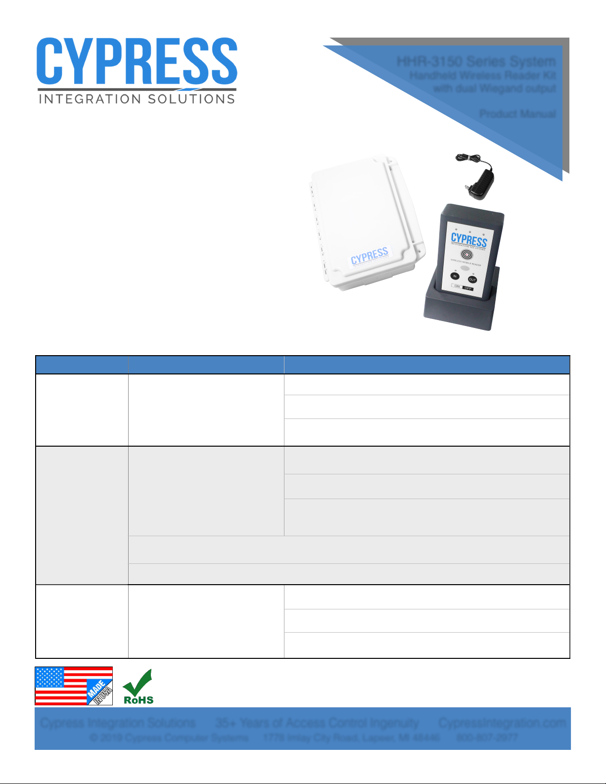
HHR-3150 Series System
Handheld Wireless Reader Kit
with dual Wiegand output
Product Manual
Cypress Integration Solutions 35+ Years of Access Control Ingenuity CypressIntegration.com
© 2019 Cypress Computer Systems 1778 Imlay City Road, Lapeer, MI 48446 800-807-2977
Ordering Information
Credential technologies
Kit components
HHR-3152-GY
(gray, UPC
816684007330)
HHR-3152-WH
(white, UPC
816684007347)
Farpointe Prox, HID Prox, AWID Prox
(125 kHz)
HHR-9052-GY / HHR-9052-WH Portable Proximity RF Card Reader/Dock
HHR-6400 Card Reader base interface
HHR-RCHL Card Reader charging unit
HHR-3156-GY
(gray, UPC
816684007354)
HHR-3156-WH
(white, UPC
816684007361)
HID Prox, EM4102, AWID Prox;
ISO14443A/B ISO15693, FeliCa™
(IDm); MIFARE Classic®, MIFARE
DESFire® 0.6, MIFARE DESFire® EV1
(32 bit CSN), HID: iCLASS® Standard/
SE/SR/Seos; PIV II, Secure Identity
Object® (SIO®)
HHR-9056-GY / HHR-9056-WH Portable Proximity RF Card Reader/Dock
HHR-6400 Card Reader base interface
HHR-RCHL Card Reader charging unit
(HID Reader Module) Global Certifications: UL Recognition (Recognized Component) to UL294 for the USA and
CSA C22.2 No. 205 for Canada. CE, FCC 47 Part 15 modular approval, RoHS, WEEE
(HID Reader Module) Government Approvals: FIPS 201 PIV II with inclusion on GSA APL
HHR-3157-GY
(gray, UPC
816684007392)
HHR-3157-WH
(white, UPC
816684007408)
Farpointe Sector, HID iClass® CSN/
UID Outputs (13.56 MHz) !
HHR-9057-GY / HHR-9057-WH Portable Proximity RF Card Reader/Dock
HHR-6400 Card Reader base interface
HHR-RCHL Card Reader charging unit

Page of 2 14
Benefits of the Cypress HHR-3150 Series Handheld Wireless Reader System
The Cypress Handheld Wireless Reader verifies credentials by wirelessly communicating with a live
database through the reader’s Base Unit. The HHR-3150 Series features a lane-selection selector on the
Handheld Reader. A vend button on the Handheld Reader controls a relay, which can be used for functions
such as controlling doors or gates, or triggering possible duress notifications.
Designed for transportation and cargo facilities; petrochemical, manufacturing, and military sites; and
healthcare and educational campuses.
Specifications
Physical
Handheld Reader
6.81” x 3.63” x 1.58” (17.30 x 9.22 x 4.01 cm) / 1.2 lbs (0.54 kg)
Charging Dock
4.76” x 4.1” x 2.2” (12.09 x 10.41 x 5.59 cm) / 0.35 lbs (0.16 kg)
Base Unit
9.25” x 7.0” x 2.25” (23.50 x 17.78 x 5.72 cm) / 1.3 lbs (0.59 kg)
Environmental
Temperature Range
-17 to 54 C
Base Unit
Weatherproof Enclosure - ABS - IP65
Electrical
Base Unit Supply Voltage
8-16Vdc Current 600mA
Handheld Reader Internal LiPo Battery Pack
7.4V 3800mAh Rechargeable (not field-serviceable)
Charging Dock
Input: 100-240 Vac, 1A, 50/60Hz Max
Relays
Max Switching
220Vdc 30W (resistive) 1A / 250Vac 37.5VA 1A
Running Spec with load
30Vdc 1A (resistive) / 125 Vac 0.3A (resistive), 1x10⁵ operations @ 20˚C
Radio
Frequency
2.4 GHz ISM band
Type
Direct Sequence Spread Spectrum (DSSS)
Transmit Power
15 dBm
Receiver Sensitivity
-103 dBm (1% PER, 250Kbps)
Modulation
O-QPSK
Agency Approvals
FCC Part 15.247: FCC ID: U90-SM220
Industry Canada (IC): 7084A-SM220
CE Certified: Certified to EN300 328 Version 1.8.1
Security Encryption
AES encryption upon request (export restrictions may apply)
Wireless
range
Indoor
150 feet* (45 meters*) Typical Range
Outdoor
500 feet* (150 meters*) Typical Range
*Note: Distances are typical line-of-sight. Actual distance may vary depending upon terrain, RF environment, building
materials, and height of antenna.
Additional
Features
AES encryption for secure communications (upon request)
Vend button controls a relay for functions such as operating gates or possible duress notification
Handheld Reader’s gate selection feature can be used for ingress and egress lanes or gates
Channel selection is factory-configured
Diagonistic indicator on base unit for determining operational status of the unit
Optional Repeaters extend distance and bypass line-of-sight issues

Page of 3 14
Tabl e of Co nt en ts
Topic
Page
Credential Technologies & Ordering Information
1
Benefits of the Cypress Handheld Wireless ReaderSystem
2
Specifications
2
Cable recommendations
4
Unpacking system components
4
Important safety information
4
Bench testing
5
System overview
5
Field installation and testing
6
Handheld Reader diagram
9
LED indicators
9
Pin layout, Base Unit
10
Base Unit and access control panel interface / wiring diagram
11
Addendum: Handheld Reader channel and address programming
12
Addendum: Reconfiguring the Base Unit radio
13
Addendum: Using the Handheld Wireless Reader system with a Cypress Repeater
14
Page of 4 14
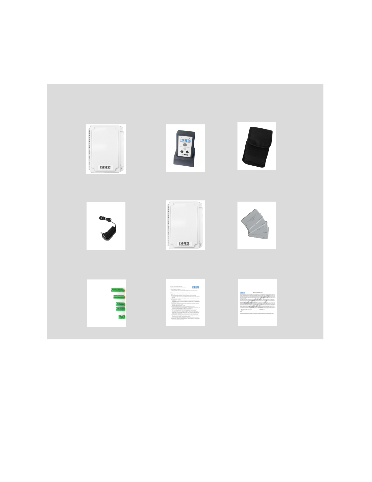
Quick-Start Guide
6 Connectors
Charger
HHR-RCHL
Handheld Rdr / Dock
(See pg. 1 for part #)
Reader Holster (opt.)
HHR-HOL3
Repeater (opt.)
RPT-5651
Base Unit
HHR-6400
Warranty
(1) 12-pin
(1) 10-pin
(2) 8-pin
(2) 2-pin
Unpacking
• Remove packaging from units and check interior of Base Unit for any shipping damage.
•
Inventory any included parts (depending on model).
HHR-3150 Series Base Unit Cable Recommendations
Wiegand and LED
PVC - Belden 9873 - 20 AWG 3 pair shielded, 500 feet max.
Plenum - Belden 83606 or 85164 - 20 AWG 3 pair shielded, 500 feet max.
Power (local)
PVC - Belden 8461 - 18 AWG 1 pair, 25 feet max.
Plenum - Belden 82740 - 18 AWG 1 pair, 25 feet max.
IMPORTANT SAFETY INSTRUCTIONS AND WARNINGS For LiPo BATTERIES
It is important to specifically use a Lithium Polymer/Li-ion charger only. Do not use a NiMH or NiCd charger.
Failure to use the proper charger may cause a fire, which could result in personal injury and property
damage.
Never charge batteries unattended. When charging LiPo/Li-ion batteries, batteries should constantly be
observed to monitor the charging process to ensure batteries are being charged properly and to respond
to potential problems which may occur.
Some LiPo/Li-ion chargers on the market may have technical deficiencies and charge the LiPo/Li-ion
batteries incorrectly or at an improper rate. It is your responsibility to ensure the charger you purchased
works properly.
If at any time a battery begins to heat, smoke, swell, or balloon, immediately stop charging the battery and
disconnect the charger, then observe the battery in a safe place for approximately 15 minutes, since the
battery could leak and react with air, causing chemicals to ignite and result in a fire. Since delayed
chemical reaction can occur, it is best to observe the battery as a safety precaution, in a safe area outside
of any building or vehicle and away from any combustible material.
Program cards (opt.)
HHR-CPC1/APC1

Page of 5 14
Bench Testing
Basics:
•
Before field-installing units, they should be tested at a convenient bench top location. This will make it
easier to verify / change settings and check operation when both units are visible, instead of far apart.
•
Handheld Reader and Base Unit should be at least 24 inches apart.
•
The Base Unit needs a suitable 8-16 Vdc power supply connected.
•
The units as shipped are configured as a matched set and are ready to power up and operate.
•
Be sure Handheld Reader is fully charged by connecting the charger cable and charging dock,
plugging the charger into an outlet and placing Reader in the charging dock (approximately 5 hours).
•
In general, the Base Unit is installed similar to a fixed reader connected to an access control panel.
•
Base Unit contains 2 boards: Board A and Board B (see pg. 10).
•
Review product manual, including Handheld Reader Features and LED Indicators (pg. 9), and
HHR-6400 Base Unit Pin Layout (pg. 10).
Bench Testing:
1. Run the following wires between the Base Unit’s Board A to a Wiegand port on the access control
panel: Data 0, Data 1, common ground, LED input.
2. Run the following wires between the Base Unit’s Board B to another Wiegand port on the access control
panel: Data 0, Data 1, common ground, LED input.
3. Connect a suitable power supply to the Base Unit (8 - 16 Volts dc; minimum of 600mA).
4. Test whether Reader is communicating with Board A on the Base Unit: Press the Power button on the
Handheld Reader. Press the “In” gate selection button.The Reader's Red LED will illuminate when
powered on, and its Blue LED will blink continuously when the Reader is communicating with the
Base Unit. The LED on Board A (in Base Unit) will also flash green.
5. Test whether Reader is communicating with Board B: Press Reader’s “Out” gate button and repeat #4.
6. Test the Handheld Reader’s gate selection feature: Press the Reader’s “In” button. The red “In” LED will
light and the Blue LED will continue to blink. Repeat sequence with the “Out” button.
7. Test a simulated valid badge read: Make sure Handheld Reader is set to “In” mode, then temporarily
connect a wire to the “LED In” and to a ground pin on the Base Unit’s Board A. While it is connected,
the Handheld Reader’s Green LED will be lit and the vibrate motor will be active. Disconnect the wire
and repeat the sequence with the Handheld Reader set to “Out” with a wire temporarily connecting
the “LED In” to a ground pin on the Base Unit’s Board B.
8. Test the Handheld Reader’s relay control: Press the “In” button, then press the Relay Control (Vend)
button. The Reader will briefly vibrate and the Base Unit’s Board A will emit an audible click. Relay
activity can also be tested with a voltage meter set to continuity mode. Repeat sequence, except
press the “Out” button; in this case, Board B will emit the audible click. Refer to relay voltage rating
in the Specifications Table on pg. 2.
9. Once the Bench Test steps are completed, the Base Unit is ready to be installed at its permanent
location, and the Handheld Reader is ready to be used.
Overview: How the HHR System Functions
The Handheld Reader system reads Wiegand RF proximity badges and sends badge data to its Base Unit
through a radio link. The Base Unit, which is installed similar to a standard fixed-mount reader, interfaces
with an access control panel.
An access control panel determines whether the badge is valid or invalid. When valid badge data is
presented, the panel will trigger an LED, Strike Relay output, or both, depending upon the type of panel.
 Loading...